EP1692729B1 - Submount for a semiconductor light emitting device and manufacturing method thereof - Google Patents
Submount for a semiconductor light emitting device and manufacturing method thereof Download PDFInfo
- Publication number
- EP1692729B1 EP1692729B1 EP04812190.9A EP04812190A EP1692729B1 EP 1692729 B1 EP1692729 B1 EP 1692729B1 EP 04812190 A EP04812190 A EP 04812190A EP 1692729 B1 EP1692729 B1 EP 1692729B1
- Authority
- EP
- European Patent Office
- Prior art keywords
- light emitting
- emitting device
- cavity
- wavelength conversion
- submount
- Prior art date
- Legal status (The legal status is an assumption and is not a legal conclusion. Google has not performed a legal analysis and makes no representation as to the accuracy of the status listed.)
- Expired - Lifetime
Links
Images


Classifications
-
- H—ELECTRICITY
- H10—SEMICONDUCTOR DEVICES; ELECTRIC SOLID-STATE DEVICES NOT OTHERWISE PROVIDED FOR
- H10H—INORGANIC LIGHT-EMITTING SEMICONDUCTOR DEVICES HAVING POTENTIAL BARRIERS
- H10H20/00—Individual inorganic light-emitting semiconductor devices having potential barriers, e.g. light-emitting diodes [LED]
- H10H20/80—Constructional details
- H10H20/85—Packages
- H10H20/851—Wavelength conversion means
- H10H20/8515—Wavelength conversion means not being in contact with the bodies
-
- H—ELECTRICITY
- H01—ELECTRIC ELEMENTS
- H01L—SEMICONDUCTOR DEVICES NOT COVERED BY CLASS H10
- H01L25/00—Assemblies consisting of a plurality of semiconductor or other solid state devices
- H01L25/16—Assemblies consisting of a plurality of semiconductor or other solid state devices the devices being of types provided for in two or more different subclasses of H10B, H10D, H10F, H10H, H10K or H10N, e.g. forming hybrid circuits
- H01L25/167—Assemblies consisting of a plurality of semiconductor or other solid state devices the devices being of types provided for in two or more different subclasses of H10B, H10D, H10F, H10H, H10K or H10N, e.g. forming hybrid circuits comprising optoelectronic devices, e.g. LED, photodiodes
-
- H—ELECTRICITY
- H01—ELECTRIC ELEMENTS
- H01L—SEMICONDUCTOR DEVICES NOT COVERED BY CLASS H10
- H01L2224/00—Indexing scheme for arrangements for connecting or disconnecting semiconductor or solid-state bodies and methods related thereto as covered by H01L24/00
- H01L2224/01—Means for bonding being attached to, or being formed on, the surface to be connected, e.g. chip-to-package, die-attach, "first-level" interconnects; Manufacturing methods related thereto
- H01L2224/42—Wire connectors; Manufacturing methods related thereto
- H01L2224/47—Structure, shape, material or disposition of the wire connectors after the connecting process
- H01L2224/48—Structure, shape, material or disposition of the wire connectors after the connecting process of an individual wire connector
- H01L2224/4805—Shape
- H01L2224/4809—Loop shape
- H01L2224/48091—Arched
-
- H—ELECTRICITY
- H01—ELECTRIC ELEMENTS
- H01L—SEMICONDUCTOR DEVICES NOT COVERED BY CLASS H10
- H01L2924/00—Indexing scheme for arrangements or methods for connecting or disconnecting semiconductor or solid-state bodies as covered by H01L24/00
- H01L2924/10—Details of semiconductor or other solid state devices to be connected
- H01L2924/102—Material of the semiconductor or solid state bodies
- H01L2924/1025—Semiconducting materials
- H01L2924/10251—Elemental semiconductors, i.e. Group IV
- H01L2924/10253—Silicon [Si]
Definitions
- This invention relates to semiconductor light emitting devices and fabricating methods therefore, and more particularly to packaging and packaging methods for semiconductor light emitting devices.
- Light emitting diodes are well known solid state electronic devices capable of generating light upon application of a sufficient voltage.
- Light emitting diodes generally comprise a p-n junction formed in an epitaxial layer deposited on a substrate, such as sapphire, silicon, silicon carbide, gallium arsenide and the like.
- the wavelength distribution of the light generated by the LED generally depends on the material from which the p-n junction is fabricated and the structure of the thin epitaxial layers that comprise the light generation region of the device.
- an LED includes an n-type substrate, an n-type epitaxial region formed on the n-type substrate and a p-type epitaxial region formed on the n-type epitaxial region.
- an anode ohmic contact may be formed on a p-type region of the device (typically, an exposed p-type epitaxial layer) and a cathode ohmic contact may be formed on an n-type region of the device (such as the substrate or an exposed n-type epitaxial layer).
- the ohmic contacts thus, may provide contact nodes for connecting the LED to an electronic circuit.
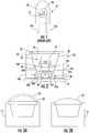
- a conventional LED 70 may be packaged in a standard package 72 that may include a conductive/reflective mounting cup 73 that, in turn, may be connected to a cathode/anode lead 75A.
- the LED chip 70 is typically mounted in the cup with a silver epoxy.
- the anode/cathode of the LED chip 70 may be wirebonded to an anode/cathode lead 75B.
- the entire package may then be encapsulated in, for example, a transparent epoxy 78.
- the encapsulant 78 may include a wavelength converter material, such as a wavelength-converting phosphor.
- some of a blue light emitted from the chip 70 stimulates the wavelength conversion material to emit longer wavelength light, such as yellow light.
- the "unconverted" blue light from the chip combines with the longer wavelength light emitted from the phosphor to synthesize white light, which may be emitted from the package.
- Flip-chip mounting of LEDs involves mounting the LED onto the submount substrate side up. Light may then be extracted and emitted through the transparent substrate.
- Flip chip mounting may be a desirable technique for mounting SiC-based LEDs. Because SiC generally has a higher index of refraction than GaN, light generated in the light emitting region may not internally reflect ( i.e. reflect back into the GaN-based layers) at the GaN/SiC interface.
- Flip chip mounting of SiC-based LEDs may offer improved light extraction when employing certain chip-shaping techniques known in the art.
- Flip chip packaging of SiC LEDs may have other benefits as well, such as improved heat extraction/dissipation, which may be desirable depending on the particular application for the chip.
- Some problems commonly encountered with conventional white LED packages relate to uniformity of emission and the size of the optical image generated by the package.
- Conventional packages tend to have a large optical image size, which is typically a function of the size of the metallic mounting cup.
- the wavelength conversion material may be distributed over a large area compared to the size of the LED chip and because the exact distribution of wavelength conversion material within the coating may be difficult to control, the uniformity and reproducibility of the light output may suffer.
- US-6,642,550B1 discloses a silicon sub-mount capable of single wire bonding and of providing ESD protection for light emitting diode devices.
- US-6,531,328B1 discloses packaging of a light-emitting diode.
- a submount for a semiconducting light emitting device is provided in accordance with claim 1.
- a method of forming a submount for a semiconductor light emitting device is provided in accordance with claim 18.
- a solid wavelength conversion member is positioned on the submount over the light emitting device to receive and wavelength convert light emitted from the light emitting device.
- the solid wavelength conversion member may be a rigid wavelength conversion member of glass, silicon and/or cured epoxy having wavelength conversion material therein.
- the wavelength conversion material may be phosphor.
- the cavity has a height from the floor to a top surface of the semiconductor substrate of at least a height of the light emitting device to be received therein.
- a receiving recess may be provided in a top surface of the semiconductor substrate adjacent the cavity. The recess may be configured to receive a solid wavelength conversion element and position the wavelength conversion element over the cavity to receive light emitting from a light emitting device in the cavity.
- a reflective material coating may be provided on the floor and/or sidewall of the cavity.
- a first external mounting pad and a second external mounting pad may be positioned on the external surface of the semiconductor substrate.
- the first conductive path may extend to the first external mounting pad and the second conductive path may extend to the second external mounting pad.
- the semiconductor substrate may be a p-type substrate and the n-type doped regions may be wells of n-type dopants in the p-type substrate.
- the first and second conductive paths may further include respective metal filled via portions extending from respective first type doped regions.
- a light emitting device package including a submount as described above further includes an encapsulant material in the cavity between the light emitting device and the wavelength conversion member.
- the encapsulant material may have a refractive index of at least about 1.5.
- light emitting device packages include a light emitting device received in the cavity and having nodes coupled to the first and second bond pads.
- a solid wavelength conversion member is positioned on a top surface of the semiconductor substrate over the light emitting device to receive and wavelength convert light emitted from the light emitting device.
- a light emitting device package is formed using the submount of the present invention by positioning the light emitting device in the cavity with a first node of the light emitting device coupled to the first bond pad and a second node of the light emitting device coupled to the second bond pad.
- a solid wavelength conversion member is positioned on the substrate over the light emitting device to receive and wavelength convert light emitted from the light emitting device. The solid wavelength conversion member may be tested prior to positioning on the substrate to determine a wavelength conversion characteristic thereof.
- first, second, etc. may be used herein to describe various elements, components, regions, layers and/or sections, these elements, components, regions, layers and/or sections should not be limited by these terms. These terms are only used to distinguish one element, component, region, layer or section from another region, layer or section. Thus, a first element, component, region, layer or section discussed below could be termed a second element, component, region, layer or section without departing from the teachings of the present invention.
- semiconductor light emitting device may include a light emitting diode, laser diode and/or other semiconductor device which includes one or more semiconductor layers, which may include silicon, silicon carbide, gallium nitride and/or other semiconductor materials, a substrate which may include sapphire, silicon, silicon carbide and/or other microelectronic substrates, and one or more contact layers which may include metal and/or other conductive layers.
- semiconductor layers which may include silicon, silicon carbide, gallium nitride and/or other semiconductor materials
- substrate which may include sapphire, silicon, silicon carbide and/or other microelectronic substrates
- contact layers which may include metal and/or other conductive layers.
- LEDs ultraviolet, blue and/or green light emitting diodes
- combinations can include AlGaInGP diodes on GaP substrates; InGaAs diodes on GaAs substrates; AlGaAs diodes on GaAs substrates; SiC diode on SiC or sapphire (Al2O3) substrate and/or a nitride-based diode on gallium nitride, silicon carbide, aluminum nitride, sapphire, zinc oxide and/or other substrates.
- the semiconductor light emitting device may be a gallium nitride-based LED or laser fabricated on a silicon carbide substrate, such as those devices manufactured and sold by Cree, Inc. of Durham, N.C.
- the present invention may be suitable for use with LEDs and/or lasers as described in U.S. Pat. Nos.
- a package for mounting a light emitting diode (LED) chip includes a semiconductor submount including therein a cavity for receiving an LED chip.
- the cavity includes a floor and a sidewall angled with respect to the floor at an angle of at least 90°.
- the package further includes at least anode and cathode bond pads on the floor of the cavity for attaching anode and cathode contacts of an LED.
- the depth of the cavity may be slightly larger than the height of the LED chip to be mounted therein.
- Conductive via connections extend through the substrate and electrically connect the anode and cathode bond pads to respective external mounting pads, which may be mounted on one or more external sidewalls of the submount.
- such conductive via connections may be used where the package is insulating and/or semi-insulating in nature.
- the external mounting pads are formed on the underside of the submount.
- the floor and sidewall surfaces of the cavity may be coated with a reflective material, such as silver, to increase reflectivity.
- an optically clear encapsulant may surround and protect the mounted LED chip within the cavity.
- the encapsulant may have a refractive index of about 1.5 or greater, which may reduce reflection at the chip/encapsulant boundary to improve light extraction.
- External mounting pads may be formed on external surfaces of the submount by plating or other methods.
- a rigid wavelength conversion element in some embodiments may be glass, silicone, epoxy or any other optically clear material with immersed wavelength conversion material and may surmount the LED chip and cover the cavity so that light escaping from the cavity passes through the wavelength conversion element and interacts with wavelength conversion material therein to produce wavelength-converted light emission.
- the rigid wavelength conversion element may be flat, curved, or may be shaped to form a thin lens having a predetermined optical transmission pattern. For example, the wavelength conversion element may have an optical transmission pattern that is matched to the optical emission pattern of a particular LED chip shape.
- the submount includes first and second heavily doped n-type regions and a heavily doped p-type region forming zener junctions with each of said first and second n-type regions.
- the anode bond pad may be in electrical contact with the first n-type region while the cathode contact may be in contact with the second n-type region.
- the anode and cathode leads to the LED chip may be connected by a pair of opposing zener diode junctions, which may provide electro-static discharge (ESD) protection to the mounted LED chip.
- ESD electro-static discharge
- the first and second heavily doped n-type regions in the submount are fabricated by implantation or diffusion of wells of n-type dopants into a p-type substrate.
- Metal-plated or metal-filled vias may connect the wells to the opposite surface of the submount for external connection.
- the size of the white image produced by the packaged device is defined by the optical cavity of the package reflector that confines the converter.
- Some embodiments of the present invention allow placement of the white converter closer to the chip, possibly reducing its image size. This may be enabled by the via electrode connectors to the outside electrode pads, which may eliminate the need for conventional wire bonds and wire bond pads inside the optical cavity.
- the white converter can be formed at the chip level, which may provide a flexible white emitter package that may be employed in various package platforms.
- some embodiments of the present invention may provide benefits from allowing use of pre-manufactured white converters that can be pre-screened to ensure that they provide the correct color point prior to being combined with a relatively high-cost LED chip.
- a pre-manufactured wavelength conversion member may also, for example, be matched to a particular light emitting device output (such as frequency or the like determined by pre-testing the particular light emitting device) and desired output of the packaged light emitting device. The result may be a chip package that may provide a reproducible and controlled white or other light emission at lower cost and improved yields.
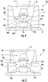
- a package 10 is provided for mounting a light emitting diode (LED) chip 12.
- the package 10 in the embodiments illustrated in Fig. 2 includes a semiconductor submount/substrate 14 having a cavity 16 therein configured to receive a light emitting device such as the LED chip 12.
- the cavity 16 includes a floor 18 and a sidewall 20.
- the sidewall 20 is angled with respect to the floor at an angle of at least about 90°.
- the cavity 16 may also have a height (depth) from the floor 18 to a top surface of the semiconductor substrate 14 of at least a height, for example, slightly larger than, a height of the LED chip 12 or other light emitting device to be mounted therein.
- the package 10 also includes an anode bond pad 22A and a cathode bond pad 22B positioned on the floor 18 of the cavity 16 for attaching anode and cathode contact nodes of the LED 12 or other light emitting device therein.
- bond pads 22A, 22B in accordance with embodiments of the present invention, a submount hybrid may be manufactured without the need for wirebonds, which may reduce the chip and/or package size.
- the semiconductor submount/substrate 14 is silicon.
- the cavity 16 may be formed in the silicon submount by etching and/or other suitable means. Silicon processing methods, including photolithography of silicon wafers to produce recesses such as cavity 16, diffusion and implantation of dopants, formation of zener diode junctions and formation of conductive vias therein, are known in the semiconductor art and will not be further described herein except as regards aspects particular to the present invention. While the description of embodiments herein will be generally presented with reference to silicon, other semiconductor materials may be used for the submount/substrate 14.
- Conductive paths extend through or into the submount/substrate 14 and electrically connect the anode 24A and cathode 24B bond pads to respective external mounting pads 26A, 26B according to the embodiments of the present invention.
- the external mounting pads 26A, 26B may be mounted on one or more walls defining an external surface 28 of the submount/substrate 14.
- the electrical vias may be formed by implantation, diffusion and/or as metallic vias by plating or similar methods. Metallic vias may have the added advantage of reducing the resistance for the heat dissipation to a circuit board or heat sink assembly.
- the external mounting pads 26A, 26B are formed on the underside of the external surface 28 of the submount/substrate 14.
- the external mounting pads 26A, 26B may be formed on external surfaces of the submount, for example, by plating or other methods.
- the floor 18 and sidewall 20 surfaces of the cavity 16 may be coated with a reflective material, such as silver, to increase reflectivity of the cavity 16.
- An optically clear encapsulant 30 may surround and/or protect the mounted light emitting device, such as LED chip 12 within the cavity 16.
- the encapsulant 30 may have a refractive index of about 1.5 or greater.
- a wavelength conversion element 32 is positioned on a top surface of the submount/substrate 14 over the light emitting device/LED chip 12.
- the wavelength conversion element 32 may be positioned in a recess 32' in the top surface of the semiconductor submount/substrate 14 adjacent the cavity 16.
- the wavelength conversion element 32 may be one or more of glass, silicone, cured epoxy and/or other optically clear material with immersed wavelength conversion material, such as a phospor.
- the wavelength conversion element 32 may cover the cavity 16 so that light escaping from the cavity 16 passes through the wavelength conversion element 32 and interacts with wavelength conversion material therein to produce a wavelength-converted light emission such as, for example, synthesized white light.
- the wavelength conversion element 32 is a solid member.
- the wavelength conversion element 32, 32', 32" in such embodiments may be a rigid, semi-rigid or flexible solid member.
- the wavelength conversion element 32, 32', 32" may have a flat cross section 32, or a curved shape 32' may be shaped to form a thin lens having a predetermined optical transmission pattern 32".
- the wavelength conversion element may have an optical transmission pattern that is matched to the optical emission pattern of a particular LED chip shape, or that is shaped to form a predetermined near- or far-field optical pattern.
- the wavelength conversion element may be flat 32 ( Figure 3A ) curved 32' ( Figure 3A ) and/or convex 32" ( Figure 3B ) and/or concave on an upper and/or a lower surface thereof opposite the light emitting device 12.
- the wavelength conversion element may also include a phosphor film, which may be deposited or otherwise embedded into the encapsulant.
- the wavelength conversion element 32 in some embodiments of the present invention may be pre-fabricated, separate from the submount, using, for example, low cost, large area manufacturing techniques such as screen printing, ink jet printing and/or uniform molding and cutting.
- the wavelength conversion element 32 may be molded and tested individually or in bulk sheets for improved uniformity of light emission before positioning on the submount/substrate 14. Pre-manufacturing and/or testing of the wavelength conversion element 32 may provide advantages in yield and the like, particularly for manufacturing wavelength conversion elements that include multiple phosphors.
- the submount/substrate 14 may include the first and second heavily doped n-type regions 34A, 34B.
- a heavily doped p-type region 36 may form schematically illustrated zener junctions 35A, 35B with the first and second n-type regions 34A, 34B.
- the junctions may be formed horizontally or vertically.
- the anode bond 22A pad may be in electrical contact with the first n-type region 34A while the cathode bond pad 22B may be in electrical contact with the second n-type region 34B.
- the anode and cathode lead nodes of a light emitting device 12 in the cavity 16 may be connected by a pair of opposing zener diode junctions (indicated schematically in Fig. 2 ) that together may provide electro-static discharge (ESD) protection to the mounted light emitting device/LED chip 12.
- ESD electro-static discharge
- the package 10 may be mounted on a substrate 31 by, for example, conventional methods.
- the substrate 31 may be, for example, a printed circuit board or metal core printed circuit board, which may provide improved heat dissipation.
- first and second heavily doped n-type regions 34A, 34B in the submount/substrate 14 of a package 100 may be fabricated, for example, by implantation or diffusion of wells of n-type dopants into a p-type substrate.
- Metal-plated vias 38A, 38B may connect the wells to the opposite surface of the submount/substrate 14 to complete first and second conductive paths to an external surface of the submount/substrate 14 for external connection. This may also reduce the thermal resistance between the LED and the heat dissipation element (heat sink, metal core PCB, etc.).
- the bond pads 22A, 22B and mounting pads 26A, 26B should generally be in direct electrical contact with the n-type regions 34A, 34B, respectively, and not the p-type region 36 (or with each other), otherwise short-circuiting of the anode and cathode connecting nodes of the LED chip 12 or the embedded zener diode junctions 35A, 35B may result. Accordingly, for example, an insulation region may be positioned between a pad 26A, 26B and the p-type region of the semiconductor substrate or the pad 26A, 26B can be limited in size so as not to overlap the p-type region.
- the package 200 may include a planar substrate 214 on which a light funnel 220 is mounted.
- Light funnel 220 may be a reflecting solid material or a transparent material having a refractive index less than the refractive index of an encapsulant 16 positioned therein so that light incident on the light funnel 220 may be internally reflected towards the wavelength conversion element 32 positioned over the cavity 16 defined by the light funnel 220.
- Embodiments of the present invention may be suitable for providing, for example, saturated color and/or white LED packages.
- some embodiments of the present invention may be used for chip-on-board assemblies that utilize a white-light emitting package having a small footprint and for other white light applications in which a small emitter size is desirable (for example for coupling into waveguides or for small pixel displays).
- some embodiments of the present invention may provide for packaging of a semiconductor light emitting device in a cavity of a submount with a solid wavelength conversion member positioned on the submount over the light emitting device to receive and wavelength convert light emitted from the device.
- p-type doped regions may be provided in an n-type doped substrate in other embodiments of the present invention.
- Further examples not forming part of the invention need not include zener diode junctions in the substrate and electrical connection to an external circuit may be provided by other means, such as by conductive vias formed through the substrate 14.
- FIG. 6 operations begin at Block 600 by forming a cavity in a semiconductor substrate configured to receive a light emitting device.
- the cavity may have a floor and a sidewall and the sidewall may be angled with respect to the floor at an angle of at least about 90°.
- First and second conductive paths are formed in the substrate extending from the cavity to an external surface of the substrate (Block 610).
- a first bond pad is formed in the cavity on an end of the first conductive path and a second bond pad is formed in the cavity on an end of the second conductive path (Block 620).
- External bond pads may be formed at ends of the respective conductive paths on an external surface of the substrate (Block 630).
- a recess may be formed on a top surface of the semiconductor substrate configured to receive a rigid wavelength conversion member (Block 640).
- An inner surface of the cavity, including a floor and/or sidewalls of the cavity, may be coated with a reflective material (Block 650).
- a submount may be a semiconductor substrate formed as described, for example, with reference to Figure 6 above.
- a light emitting device is positioned in a cavity of the submount/substrate (Block 710).
- a first node of the light emitting device may be positioned in contact with the first bond pad formed in the cavity and the second node of the light emitting device may be placed in contact with a second bond pad formed in a cavity of the substrate.
- a solid wavelength conversion member may be pre-tested to determine a wavelength conversion characteristic thereof (Block 720). Such testing may provide for a higher yield of the formed light emitting device package by testing the wavelength characteristics of the wavelength conversion member before attachment of the same to the light emitting device package. After testing, the solid wavelength conversion member is positioned on the substrate over the light emitting device to receive and wavelength convert light emitted from the light emitting device (Block 730).
- the wavelength conversion member as illustrated in Figures 3A and 3B , may have either a flat and/or concave shape on an upper surface of the wavelength conversion member opposite the light emitting device mounted in the cavity.
- FIG. 6 and 7 The flowcharts of Figs. 6 and 7 and the schematic illustrations of Figs. 2 through 5 illustrate the functionality and operation of possible implementations of methods for forming a submount and/or a light emitting device package. It should be noted that, in some alternative implementations, the acts noted in describing the figures may occur out of the order noted in the figures. For example, two blocks/operations shown in succession may, in fact, be executed substantially concurrently, or may be executed in the reverse order, depending upon the functionality involved.
- mounting of an LED chip in a recessed cavity of a semiconductor substrate chip carrier/submount may provide a white emitting chip with a small optical image size, not substantially larger than the LED chip itself.
- the recessed cavity may act as an optical cavity and light concentrator.
- the mounted LED chip may also provide the means to place a pre-manufactured or in-situ formed white converter element in close proximity over the LED chip. This placement may provide for an image size of the white emitter that is substantially the same as that of the LED chip.
- the submount may be integrated into conventional electronic packages.
- the submount may also be encapsulated itself, which may improve its mechanical stability, to provide a stand alone chip-scale package.
Landscapes
- Engineering & Computer Science (AREA)
- Microelectronics & Electronic Packaging (AREA)
- Physics & Mathematics (AREA)
- Condensed Matter Physics & Semiconductors (AREA)
- General Physics & Mathematics (AREA)
- Computer Hardware Design (AREA)
- Power Engineering (AREA)
- Led Device Packages (AREA)
Applications Claiming Priority (3)
| Application Number | Priority Date | Filing Date | Title |
|---|---|---|---|
| US52805403P | 2003-12-09 | 2003-12-09 | |
| US10/987,894 US7518158B2 (en) | 2003-12-09 | 2004-11-12 | Semiconductor light emitting devices and submounts |
| PCT/US2004/039619 WO2005062393A2 (en) | 2003-12-09 | 2004-11-24 | Semiconductor light emitting devices and submounts and methods for forming the same |
Publications (2)
| Publication Number | Publication Date |
|---|---|
| EP1692729A2 EP1692729A2 (en) | 2006-08-23 |
| EP1692729B1 true EP1692729B1 (en) | 2020-02-12 |
Family
ID=34636672
Family Applications (1)
| Application Number | Title | Priority Date | Filing Date |
|---|---|---|---|
| EP04812190.9A Expired - Lifetime EP1692729B1 (en) | 2003-12-09 | 2004-11-24 | Submount for a semiconductor light emitting device and manufacturing method thereof |
Country Status (7)
| Country | Link |
|---|---|
| US (3) | US7518158B2 (enExample) |
| EP (1) | EP1692729B1 (enExample) |
| JP (2) | JP4870572B2 (enExample) |
| KR (1) | KR101097694B1 (enExample) |
| CA (1) | CA2547832A1 (enExample) |
| TW (1) | TW200531312A (enExample) |
| WO (1) | WO2005062393A2 (enExample) |
Families Citing this family (87)
| Publication number | Priority date | Publication date | Assignee | Title |
|---|---|---|---|---|
| US7638346B2 (en) * | 2001-12-24 | 2009-12-29 | Crystal Is, Inc. | Nitride semiconductor heterostructures and related methods |
| US20060005763A1 (en) * | 2001-12-24 | 2006-01-12 | Crystal Is, Inc. | Method and apparatus for producing large, single-crystals of aluminum nitride |
| US8545629B2 (en) | 2001-12-24 | 2013-10-01 | Crystal Is, Inc. | Method and apparatus for producing large, single-crystals of aluminum nitride |
| US7518158B2 (en) | 2003-12-09 | 2009-04-14 | Cree, Inc. | Semiconductor light emitting devices and submounts |
| EP1587151A3 (en) * | 2004-04-17 | 2011-09-28 | LG Electronics, Inc. | Semiconductor light emitting device and fabrication method thereof |
| US8154030B2 (en) * | 2004-10-01 | 2012-04-10 | Finisar Corporation | Integrated diode in a silicon chip scale package |
| TW200637033A (en) * | 2004-11-22 | 2006-10-16 | Matsushita Electric Industrial Co Ltd | Light-emitting device, light-emitting module, display unit, lighting unit and method for manufacturing light-emitting device |
| US20060258031A1 (en) * | 2005-01-26 | 2006-11-16 | Bily Wang | Wafer-level electro-optical semiconductor manufacture fabrication method |
| US20100301349A1 (en) * | 2005-01-26 | 2010-12-02 | Harvatek Corporation | Wafer level led package structure for increasing light-emitting efficiency and heat-dissipating effect and method for manufacturing the same |
| US8079743B2 (en) * | 2005-06-28 | 2011-12-20 | Lighting Science Group Corporation | Display backlight with improved light coupling and mixing |
| US7719021B2 (en) * | 2005-06-28 | 2010-05-18 | Lighting Science Group Corporation | Light efficient LED assembly including a shaped reflective cavity and method for making same |
| CN100405621C (zh) * | 2005-09-29 | 2008-07-23 | 上海乐金广电电子有限公司 | 白色光源的制造方法 |
| EP1954857B1 (en) | 2005-12-02 | 2018-09-26 | Crystal Is, Inc. | Doped aluminum nitride crystals and methods of making them |
| JP2007165811A (ja) | 2005-12-16 | 2007-06-28 | Nichia Chem Ind Ltd | 発光装置 |
| US8044412B2 (en) | 2006-01-20 | 2011-10-25 | Taiwan Semiconductor Manufacturing Company, Ltd | Package for a light emitting element |
| US7528422B2 (en) * | 2006-01-20 | 2009-05-05 | Hymite A/S | Package for a light emitting element with integrated electrostatic discharge protection |
| US7928462B2 (en) * | 2006-02-16 | 2011-04-19 | Lg Electronics Inc. | Light emitting device having vertical structure, package thereof and method for manufacturing the same |
| KR100746783B1 (ko) * | 2006-02-28 | 2007-08-06 | 엘지전자 주식회사 | 발광소자 패키지 및 그 제조방법 |
| TWI303872B (en) * | 2006-03-13 | 2008-12-01 | Ind Tech Res Inst | High power light emitting device assembly with esd preotection ability and the method of manufacturing the same |
| US8012257B2 (en) * | 2006-03-30 | 2011-09-06 | Crystal Is, Inc. | Methods for controllable doping of aluminum nitride bulk crystals |
| US9034103B2 (en) * | 2006-03-30 | 2015-05-19 | Crystal Is, Inc. | Aluminum nitride bulk crystals having high transparency to ultraviolet light and methods of forming them |
| KR101314713B1 (ko) * | 2006-06-16 | 2013-10-07 | 신꼬오덴기 고교 가부시키가이샤 | 반도체 장치, 그 제조 방법, 및 기판 |
| KR100854328B1 (ko) * | 2006-07-07 | 2008-08-28 | 엘지전자 주식회사 | 발광 소자 패키지 및 그 제조방법 |
| KR100845856B1 (ko) * | 2006-12-21 | 2008-07-14 | 엘지전자 주식회사 | 발광 소자 패키지 및 그 제조방법 |
| DE102007001706A1 (de) * | 2007-01-11 | 2008-07-17 | Osram Opto Semiconductors Gmbh | Gehäuse für optoelektronisches Bauelement und Anordnung eines optoelektronischen Bauelementes in einem Gehäuse |
| US9771666B2 (en) | 2007-01-17 | 2017-09-26 | Crystal Is, Inc. | Defect reduction in seeded aluminum nitride crystal growth |
| US8323406B2 (en) * | 2007-01-17 | 2012-12-04 | Crystal Is, Inc. | Defect reduction in seeded aluminum nitride crystal growth |
| CN101652832B (zh) * | 2007-01-26 | 2011-06-22 | 晶体公司 | 厚的赝晶氮化物外延层 |
| US8080833B2 (en) * | 2007-01-26 | 2011-12-20 | Crystal Is, Inc. | Thick pseudomorphic nitride epitaxial layers |
| EP1988577B1 (en) * | 2007-04-30 | 2017-04-05 | Tridonic Jennersdorf GmbH | Light emitting diode module with silicon platform |
| US8088220B2 (en) | 2007-05-24 | 2012-01-03 | Crystal Is, Inc. | Deep-eutectic melt growth of nitride crystals |
| US8436371B2 (en) * | 2007-05-24 | 2013-05-07 | Cree, Inc. | Microscale optoelectronic device packages |
| US7791096B2 (en) * | 2007-06-08 | 2010-09-07 | Koninklijke Philips Electronics N.V. | Mount for a semiconductor light emitting device |
| TWM327545U (en) * | 2007-07-09 | 2008-02-21 | Everlight Electronics Co Ltd | Improved light-emitting diode packaging structure |
| JP4809308B2 (ja) * | 2007-09-21 | 2011-11-09 | 新光電気工業株式会社 | 基板の製造方法 |
| JP4961617B2 (ja) * | 2007-10-01 | 2012-06-27 | 新光電気工業株式会社 | 配線基板とその製造方法及び半導体装置 |
| KR100896282B1 (ko) * | 2007-11-01 | 2009-05-08 | 엘지전자 주식회사 | 발광 소자 패키지 및 그 제조방법 |
| US8536584B2 (en) * | 2007-11-14 | 2013-09-17 | Cree, Inc. | High voltage wire bond free LEDS |
| US7985970B2 (en) | 2009-04-06 | 2011-07-26 | Cree, Inc. | High voltage low current surface-emitting LED |
| KR100999760B1 (ko) * | 2008-09-26 | 2010-12-08 | 엘지이노텍 주식회사 | 발광소자 패키지 및 그 제조방법 |
| US20100176507A1 (en) * | 2009-01-14 | 2010-07-15 | Hymite A/S | Semiconductor-based submount with electrically conductive feed-throughs |
| KR101064026B1 (ko) * | 2009-02-17 | 2011-09-08 | 엘지이노텍 주식회사 | 발광 디바이스 패키지 및 그 제조방법 |
| US9093293B2 (en) | 2009-04-06 | 2015-07-28 | Cree, Inc. | High voltage low current surface emitting light emitting diode |
| US8476668B2 (en) * | 2009-04-06 | 2013-07-02 | Cree, Inc. | High voltage low current surface emitting LED |
| US20100314551A1 (en) * | 2009-06-11 | 2010-12-16 | Bettles Timothy J | In-line Fluid Treatment by UV Radiation |
| US8084780B2 (en) * | 2009-08-13 | 2011-12-27 | Semileds Optoelectronics Co. | Smart integrated semiconductor light emitting system including light emitting diodes and application specific integrated circuits (ASIC) |
| US8933467B2 (en) | 2009-08-13 | 2015-01-13 | SemiLEDs Optoelectronics Co., Ltd. | Smart integrated semiconductor light emitting system including nitride based light emitting diodes (LED) and application specific integrated circuits (ASIC) |
| US9214456B2 (en) | 2009-08-13 | 2015-12-15 | SemiLEDs Optoelectronics Co., Ltd. | Light emitting diode (LED) system having lighting device and wireless control system |
| US20110042803A1 (en) * | 2009-08-24 | 2011-02-24 | Chen-Fu Chu | Method For Fabricating A Through Interconnect On A Semiconductor Substrate |
| KR101092097B1 (ko) * | 2009-08-31 | 2011-12-12 | 엘지이노텍 주식회사 | 발광 다이오드 패키지 및 그 제조방법 |
| US7893445B2 (en) * | 2009-11-09 | 2011-02-22 | Cree, Inc. | Solid state emitter package including red and blue emitters |
| DE102009053064A1 (de) * | 2009-11-13 | 2011-05-19 | Osram Opto Semiconductors Gmbh | Dünnfilm-Halbleiterbauelement mit Schutzdiodenstruktur und Verfahren zur Herstellung eines Dünnfilm-Halbleiterbauelements |
| US20110175218A1 (en) | 2010-01-18 | 2011-07-21 | Shiann-Ming Liou | Package assembly having a semiconductor substrate |
| US20110186960A1 (en) | 2010-02-03 | 2011-08-04 | Albert Wu | Techniques and configurations for recessed semiconductor substrates |
| CN105951177B (zh) | 2010-06-30 | 2018-11-02 | 晶体公司 | 使用热梯度控制的大块氮化铝单晶的生长 |
| JPWO2012002580A1 (ja) | 2010-07-01 | 2013-09-02 | シチズンホールディングス株式会社 | Led光源装置及びその製造方法 |
| DE102010027679A1 (de) * | 2010-07-20 | 2012-01-26 | Osram Opto Semiconductors Gmbh | Optoelektronisches Bauelement |
| WO2012016377A1 (en) | 2010-08-03 | 2012-02-09 | Industrial Technology Research Institute | Light emitting diode chip, light emitting diode package structure, and method for forming the same |
| US8455882B2 (en) | 2010-10-15 | 2013-06-04 | Cree, Inc. | High efficiency LEDs |
| CN102456802A (zh) * | 2010-10-19 | 2012-05-16 | 展晶科技(深圳)有限公司 | 发光二极管封装结构的制造方法 |
| US9022608B2 (en) | 2010-11-23 | 2015-05-05 | Q Technology, Inc. | Unlit LED circuit bypass element with system and method therefor |
| US8772817B2 (en) | 2010-12-22 | 2014-07-08 | Cree, Inc. | Electronic device submounts including substrates with thermally conductive vias |
| KR101761834B1 (ko) | 2011-01-28 | 2017-07-27 | 서울바이오시스 주식회사 | 웨이퍼 레벨 발광 다이오드 패키지 및 그것을 제조하는 방법 |
| KR101766297B1 (ko) * | 2011-02-16 | 2017-08-08 | 삼성전자 주식회사 | 발광소자 패키지 및 그 제조방법 |
| US8962359B2 (en) | 2011-07-19 | 2015-02-24 | Crystal Is, Inc. | Photon extraction from nitride ultraviolet light-emitting devices |
| KR20130011088A (ko) * | 2011-07-20 | 2013-01-30 | 삼성전자주식회사 | 발광소자 패키지 및 그 제조방법 |
| WO2013016355A1 (en) * | 2011-07-25 | 2013-01-31 | Cree, Inc. | Monolithic multi-junction light emitting devices including multiple groups of light emitting diodes |
| WO2013027413A1 (ja) * | 2011-08-25 | 2013-02-28 | パナソニック株式会社 | 保護素子及びこれを用いた発光装置 |
| TWI449466B (zh) | 2011-12-26 | 2014-08-11 | Ind Tech Res Inst | 發光裝置 |
| JP2014067934A (ja) * | 2012-09-27 | 2014-04-17 | Murata Mfg Co Ltd | 実装基板の製造方法および実装基板 |
| JP6275817B2 (ja) | 2013-03-15 | 2018-02-07 | クリスタル アイエス, インコーポレーテッドCrystal Is, Inc. | 仮像電子及び光学電子装置に対する平面コンタクト |
| DE102013105631A1 (de) * | 2013-05-31 | 2014-12-04 | Osram Opto Semiconductors Gmbh | Träger für einen optoelektronischen Halbleiterchip und optoelektronisches Bauteil |
| JP6454698B2 (ja) * | 2013-06-28 | 2019-01-16 | コーニンクレッカ フィリップス エヌ ヴェKoninklijke Philips N.V. | 発光ダイオードデバイス |
| KR102130524B1 (ko) * | 2013-08-28 | 2020-07-07 | 삼성디스플레이 주식회사 | 발광 소자 모듈, 이를 포함하는 백라이트 유닛 및 이를 포함하는 액정 표시 장치 |
| DE102013110853B4 (de) * | 2013-10-01 | 2020-12-24 | OSRAM Opto Semiconductors Gesellschaft mit beschränkter Haftung | Strahlungsemittierender Halbleiterchip und Verfahren zur Herstellung von strahlungsemittierenden Halbleiterchips |
| JP6539035B2 (ja) | 2014-01-08 | 2019-07-03 | ローム株式会社 | チップ部品 |
| US20150303179A1 (en) * | 2014-04-18 | 2015-10-22 | Toshiba Corporation | Light Emitting Diode Assembly With Integrated Circuit Element |
| TWM488746U (zh) * | 2014-07-14 | 2014-10-21 | 新世紀光電股份有限公司 | 發光模組 |
| US20170104135A1 (en) * | 2015-10-13 | 2017-04-13 | Sensor Electronic Technology, Inc. | Light Emitting Diode Mounting Structure |
| WO2018200685A2 (en) | 2017-04-27 | 2018-11-01 | Ecosense Lighting Inc. | Methods and systems for an automated design, fulfillment, deployment and operation platform for lighting installations |
| KR102667851B1 (ko) * | 2016-02-22 | 2024-05-23 | 삼성디스플레이 주식회사 | 디스플레이 장치 |
| US10522532B2 (en) * | 2016-05-27 | 2019-12-31 | Taiwan Semiconductor Manufacturing Co., Ltd. | Through via extending through a group III-V layer |
| WO2018022061A1 (en) * | 2016-07-28 | 2018-02-01 | Victor Equipment Company | Fuel tip with integrated flashback arrestor |
| CN107369677A (zh) * | 2017-08-10 | 2017-11-21 | 中国科学院福建物质结构研究所 | 一种集成封装的三基色led器件及其制作方法和用途 |
| US10770636B2 (en) * | 2018-02-14 | 2020-09-08 | Epistar Corporation | Light emitting device and manufacturing method thereof |
| CN110164857B (zh) * | 2018-02-14 | 2024-04-09 | 晶元光电股份有限公司 | 发光装置 |
| DE102020126391A1 (de) | 2020-10-08 | 2022-04-14 | OSRAM Opto Semiconductors Gesellschaft mit beschränkter Haftung | Led package für uv licht und verfahren |
Citations (1)
| Publication number | Priority date | Publication date | Assignee | Title |
|---|---|---|---|---|
| US6531328B1 (en) * | 2001-10-11 | 2003-03-11 | Solidlite Corporation | Packaging of light-emitting diode |
Family Cites Families (50)
| Publication number | Priority date | Publication date | Assignee | Title |
|---|---|---|---|---|
| KR880014692A (ko) * | 1987-05-30 | 1988-12-24 | 강진구 | 반사경이 부착된 반도체 발광장치 |
| US5027168A (en) * | 1988-12-14 | 1991-06-25 | Cree Research, Inc. | Blue light emitting diode formed in silicon carbide |
| US4918497A (en) * | 1988-12-14 | 1990-04-17 | Cree Research, Inc. | Blue light emitting diode formed in silicon carbide |
| US4966862A (en) * | 1989-08-28 | 1990-10-30 | Cree Research, Inc. | Method of production of light emitting diodes |
| US5210051A (en) * | 1990-03-27 | 1993-05-11 | Cree Research, Inc. | High efficiency light emitting diodes from bipolar gallium nitride |
| US5416342A (en) * | 1993-06-23 | 1995-05-16 | Cree Research, Inc. | Blue light-emitting diode with high external quantum efficiency |
| US5338944A (en) * | 1993-09-22 | 1994-08-16 | Cree Research, Inc. | Blue light-emitting diode with degenerate junction structure |
| US5393993A (en) * | 1993-12-13 | 1995-02-28 | Cree Research, Inc. | Buffer structure between silicon carbide and gallium nitride and resulting semiconductor devices |
| US5604135A (en) * | 1994-08-12 | 1997-02-18 | Cree Research, Inc. | Method of forming green light emitting diode in silicon carbide |
| US5523589A (en) * | 1994-09-20 | 1996-06-04 | Cree Research, Inc. | Vertical geometry light emitting diode with group III nitride active layer and extended lifetime |
| US5631190A (en) * | 1994-10-07 | 1997-05-20 | Cree Research, Inc. | Method for producing high efficiency light-emitting diodes and resulting diode structures |
| US5739554A (en) * | 1995-05-08 | 1998-04-14 | Cree Research, Inc. | Double heterojunction light emitting diode with gallium nitride active layer |
| BR9709998B1 (pt) | 1996-06-26 | 2010-04-20 | elemento de construção semicondutor, irradiador de luz, com elemento de conversão de luminescência | |
| JPH1074986A (ja) | 1996-06-27 | 1998-03-17 | Natl Aerospace Lab | 熱電変換素子、π型熱電変換素子対および熱電変換モジュールの各製造方法 |
| JP3196823B2 (ja) | 1997-06-11 | 2001-08-06 | 日本電気株式会社 | 半導体装置 |
| US6201262B1 (en) * | 1997-10-07 | 2001-03-13 | Cree, Inc. | Group III nitride photonic devices on silicon carbide substrates with conductive buffer interlay structure |
| JPH11251644A (ja) * | 1998-02-27 | 1999-09-17 | Matsushita Electron Corp | 半導体発光装置 |
| JP3893735B2 (ja) * | 1998-04-24 | 2007-03-14 | 松下電器産業株式会社 | 発光装置 |
| JP4042213B2 (ja) * | 1998-06-05 | 2008-02-06 | 松下電器産業株式会社 | フルカラー半導体発光装置 |
| JP2001015815A (ja) * | 1999-04-28 | 2001-01-19 | Sanken Electric Co Ltd | 半導体発光装置 |
| JP4350232B2 (ja) * | 1999-10-05 | 2009-10-21 | 株式会社朝日ラバー | 蛍光被覆体製造支援方法、及びその製造支援システム |
| US6303509B1 (en) * | 1999-10-29 | 2001-10-16 | Taiwan Semiconductor Manufacturing Company | Method to calibrate the wafer transfer for oxide etcher (with clamp) |
| JP2002190622A (ja) | 2000-12-22 | 2002-07-05 | Sanken Electric Co Ltd | 発光ダイオード用透光性蛍光カバー |
| US6747406B1 (en) * | 2000-08-07 | 2004-06-08 | General Electric Company | LED cross-linkable phospor coating |
| US6635363B1 (en) * | 2000-08-21 | 2003-10-21 | General Electric Company | Phosphor coating with self-adjusting distance from LED chip |
| US20020063520A1 (en) * | 2000-11-29 | 2002-05-30 | Huei-Che Yu | Pre-formed fluorescent plate - LED device |
| JP5110744B2 (ja) | 2000-12-21 | 2012-12-26 | フィリップス ルミレッズ ライティング カンパニー リミテッド ライアビリティ カンパニー | 発光装置及びその製造方法 |
| US20020084749A1 (en) * | 2000-12-28 | 2002-07-04 | Ayala Raul E. | UV reflecting materials for LED lamps using UV-emitting diodes |
| JP2002220350A (ja) | 2001-01-24 | 2002-08-09 | Toshiba Corp | 有害塩素化合物処理方法および処理装置 |
| JP4737842B2 (ja) | 2001-01-30 | 2011-08-03 | 京セラ株式会社 | 発光素子収納用パッケージの製造方法 |
| US6791119B2 (en) * | 2001-02-01 | 2004-09-14 | Cree, Inc. | Light emitting diodes including modifications for light extraction |
| TW490863B (en) * | 2001-02-12 | 2002-06-11 | Arima Optoelectronics Corp | Manufacturing method of LED with uniform color temperature |
| JP2002314143A (ja) | 2001-04-09 | 2002-10-25 | Toshiba Corp | 発光装置 |
| US6958497B2 (en) * | 2001-05-30 | 2005-10-25 | Cree, Inc. | Group III nitride based light emitting diode structures with a quantum well and superlattice, group III nitride based quantum well structures and group III nitride based superlattice structures |
| US20030102473A1 (en) * | 2001-08-15 | 2003-06-05 | Motorola, Inc. | Structure and method for fabricating semiconductor structures and devices utilizing the formation of a compliant substrate |
| US7858403B2 (en) * | 2001-10-31 | 2010-12-28 | Cree, Inc. | Methods and systems for fabricating broad spectrum light emitting devices |
| US6791116B2 (en) * | 2002-04-30 | 2004-09-14 | Toyoda Gosei Co., Ltd. | Light emitting diode |
| JP2003347601A (ja) | 2002-05-28 | 2003-12-05 | Matsushita Electric Works Ltd | 発光ダイオード照明装置 |
| US6642550B1 (en) * | 2002-08-26 | 2003-11-04 | California Micro Devices | Silicon sub-mount capable of single wire bonding and of providing ESD protection for light emitting diode devices |
| US7264378B2 (en) * | 2002-09-04 | 2007-09-04 | Cree, Inc. | Power surface mount light emitting die package |
| US7244965B2 (en) * | 2002-09-04 | 2007-07-17 | Cree Inc, | Power surface mount light emitting die package |
| ATE543221T1 (de) * | 2002-09-19 | 2012-02-15 | Cree Inc | Leuchtstoffbeschichtete leuchtdioden mit verjüngten seitenwänden und herstellungsverfahren dafür |
| JP4201167B2 (ja) * | 2002-09-26 | 2008-12-24 | シチズン電子株式会社 | 白色発光装置の製造方法 |
| US6936857B2 (en) * | 2003-02-18 | 2005-08-30 | Gelcore, Llc | White light LED device |
| US6876008B2 (en) * | 2003-07-31 | 2005-04-05 | Lumileds Lighting U.S., Llc | Mount for semiconductor light emitting device |
| US7518158B2 (en) * | 2003-12-09 | 2009-04-14 | Cree, Inc. | Semiconductor light emitting devices and submounts |
| US7553683B2 (en) * | 2004-06-09 | 2009-06-30 | Philips Lumiled Lighting Co., Llc | Method of forming pre-fabricated wavelength converting elements for semiconductor light emitting devices |
| JP2006012868A (ja) * | 2004-06-22 | 2006-01-12 | Toshiba Corp | 半導体発光素子用パッケージおよびそれを用いた半導体発光装置 |
| JP4862274B2 (ja) * | 2005-04-20 | 2012-01-25 | パナソニック電工株式会社 | 発光装置の製造方法及び該発光装置を用いた発光装置ユニットの製造方法 |
| JP4980640B2 (ja) * | 2006-03-31 | 2012-07-18 | 三洋電機株式会社 | 照明装置 |
-
2004
- 2004-11-12 US US10/987,894 patent/US7518158B2/en active Active
- 2004-11-24 JP JP2006543856A patent/JP4870572B2/ja not_active Expired - Fee Related
- 2004-11-24 WO PCT/US2004/039619 patent/WO2005062393A2/en not_active Ceased
- 2004-11-24 EP EP04812190.9A patent/EP1692729B1/en not_active Expired - Lifetime
- 2004-11-24 CA CA002547832A patent/CA2547832A1/en not_active Abandoned
- 2004-12-09 TW TW093138180A patent/TW200531312A/zh unknown
-
2006
- 2006-06-07 KR KR1020067011189A patent/KR101097694B1/ko not_active Expired - Fee Related
-
2009
- 2009-03-04 US US12/397,555 patent/US8138000B2/en not_active Expired - Lifetime
-
2011
- 2011-07-04 JP JP2011147906A patent/JP2011193030A/ja active Pending
-
2012
- 2012-02-14 US US13/372,765 patent/US8847257B2/en not_active Expired - Lifetime
Patent Citations (1)
| Publication number | Priority date | Publication date | Assignee | Title |
|---|---|---|---|---|
| US6531328B1 (en) * | 2001-10-11 | 2003-03-11 | Solidlite Corporation | Packaging of light-emitting diode |
Also Published As
| Publication number | Publication date |
|---|---|
| CA2547832A1 (en) | 2005-07-07 |
| JP2011193030A (ja) | 2011-09-29 |
| WO2005062393A2 (en) | 2005-07-07 |
| KR20070041663A (ko) | 2007-04-19 |
| EP1692729A2 (en) | 2006-08-23 |
| US20090159918A1 (en) | 2009-06-25 |
| US8138000B2 (en) | 2012-03-20 |
| JP2007535130A (ja) | 2007-11-29 |
| KR101097694B1 (ko) | 2011-12-22 |
| JP4870572B2 (ja) | 2012-02-08 |
| US8847257B2 (en) | 2014-09-30 |
| WO2005062393A3 (en) | 2006-01-05 |
| TW200531312A (en) | 2005-09-16 |
| US20120138996A1 (en) | 2012-06-07 |
| US20050121686A1 (en) | 2005-06-09 |
| US7518158B2 (en) | 2009-04-14 |
Similar Documents
| Publication | Publication Date | Title |
|---|---|---|
| EP1692729B1 (en) | Submount for a semiconductor light emitting device and manufacturing method thereof | |
| EP1774598B1 (en) | Chip-scale methods for packaging light emitting devices and chip-scale packaged light emitting devices | |
| US7977686B2 (en) | Chip-scale methods for packaging light emitting devices and chip-scale packaged light emitting devices | |
| KR101010230B1 (ko) | 발광 장치 | |
| EP2264797B1 (en) | Light-emitting device | |
| KR100610650B1 (ko) | 엘이디 패키지 및 그 제조방법 | |
| US9583681B2 (en) | Light emitter device packages, modules and methods | |
| KR20050034936A (ko) | 형광체를 이용한 파장변환형 발광 다이오드 패키지 및제조방법 | |
| KR20160017849A (ko) | 고출력 발광 장치 및 그 제조 방법 | |
| TWI395346B (zh) | 發光元件的封裝結構 | |
| KR20120039587A (ko) | 웨이퍼 레벨 발광다이오드 패키지 | |
| CN100474640C (zh) | 半导体发光器件和子支架及其形成方法 | |
| KR101778141B1 (ko) | 반도체 발광소자 및 이의 제조방법 | |
| JP2008124500A (ja) | 発光装置 | |
| JP6978708B2 (ja) | 半導体発光装置 | |
| KR100813070B1 (ko) | 발광 소자 패키지 및 그 제조방법 | |
| JP2022010198A (ja) | 半導体発光装置 | |
| KR20170104695A (ko) | 반도체 발광소자 |
Legal Events
| Date | Code | Title | Description |
|---|---|---|---|
| PUAI | Public reference made under article 153(3) epc to a published international application that has entered the european phase |
Free format text: ORIGINAL CODE: 0009012 |
|
| AK | Designated contracting states |
Kind code of ref document: A2 Designated state(s): AT BE BG CH CY CZ DE DK EE ES FI FR GB GR HU IE IS IT LI LU MC NL PL PT RO SE SI SK TR |
|
| 17P | Request for examination filed |
Effective date: 20060515 |
|
| RIN1 | Information on inventor provided before grant (corrected) |
Inventor name: HILLER, NORBERT Inventor name: ANDREWS, PETER, S. Inventor name: NEGLEY, GERALD, H. Inventor name: IBBETSON, JAMES Inventor name: KELLER, BERND |
|
| DAX | Request for extension of the european patent (deleted) | ||
| 17Q | First examination report despatched |
Effective date: 20120326 |
|
| STAA | Information on the status of an ep patent application or granted ep patent |
Free format text: STATUS: EXAMINATION IS IN PROGRESS |
|
| GRAP | Despatch of communication of intention to grant a patent |
Free format text: ORIGINAL CODE: EPIDOSNIGR1 |
|
| STAA | Information on the status of an ep patent application or granted ep patent |
Free format text: STATUS: GRANT OF PATENT IS INTENDED |
|
| INTG | Intention to grant announced |
Effective date: 20190816 |
|
| RIN1 | Information on inventor provided before grant (corrected) |
Inventor name: KELLER, BERND Inventor name: ANDREWS, PETER, S. Inventor name: NEGLEY, GERALD, H. Inventor name: IBBETSON, JAMES Inventor name: HILLER, NORBERT |
|
| GRAS | Grant fee paid |
Free format text: ORIGINAL CODE: EPIDOSNIGR3 |
|
| GRAA | (expected) grant |
Free format text: ORIGINAL CODE: 0009210 |
|
| STAA | Information on the status of an ep patent application or granted ep patent |
Free format text: STATUS: THE PATENT HAS BEEN GRANTED |
|
| REG | Reference to a national code |
Ref country code: DE Ref legal event code: R081 Ref document number: 602004054513 Country of ref document: DE Owner name: CREELED, INC. (N. D. GES. D. STAATES DELAWARE), US Free format text: FORMER OWNER: CREE, INC., DURHAM, N.C., US |
|
| AK | Designated contracting states |
Kind code of ref document: B1 Designated state(s): AT BE BG CH CY CZ DE DK EE ES FI FR GB GR HU IE IS IT LI LU MC NL PL PT RO SE SI SK TR |
|
| REG | Reference to a national code |
Ref country code: GB Ref legal event code: FG4D |
|
| REG | Reference to a national code |
Ref country code: CH Ref legal event code: EP |
|
| REG | Reference to a national code |
Ref country code: AT Ref legal event code: REF Ref document number: 1233251 Country of ref document: AT Kind code of ref document: T Effective date: 20200215 |
|
| REG | Reference to a national code |
Ref country code: IE Ref legal event code: FG4D |
|
| REG | Reference to a national code |
Ref country code: DE Ref legal event code: R096 Ref document number: 602004054513 Country of ref document: DE |
|
| PG25 | Lapsed in a contracting state [announced via postgrant information from national office to epo] |
Ref country code: FI Free format text: LAPSE BECAUSE OF FAILURE TO SUBMIT A TRANSLATION OF THE DESCRIPTION OR TO PAY THE FEE WITHIN THE PRESCRIBED TIME-LIMIT Effective date: 20200212 |
|
| REG | Reference to a national code |
Ref country code: NL Ref legal event code: MP Effective date: 20200212 |
|
| PG25 | Lapsed in a contracting state [announced via postgrant information from national office to epo] |
Ref country code: IS Free format text: LAPSE BECAUSE OF FAILURE TO SUBMIT A TRANSLATION OF THE DESCRIPTION OR TO PAY THE FEE WITHIN THE PRESCRIBED TIME-LIMIT Effective date: 20200612 Ref country code: BG Free format text: LAPSE BECAUSE OF FAILURE TO SUBMIT A TRANSLATION OF THE DESCRIPTION OR TO PAY THE FEE WITHIN THE PRESCRIBED TIME-LIMIT Effective date: 20200512 Ref country code: GR Free format text: LAPSE BECAUSE OF FAILURE TO SUBMIT A TRANSLATION OF THE DESCRIPTION OR TO PAY THE FEE WITHIN THE PRESCRIBED TIME-LIMIT Effective date: 20200513 Ref country code: SE Free format text: LAPSE BECAUSE OF FAILURE TO SUBMIT A TRANSLATION OF THE DESCRIPTION OR TO PAY THE FEE WITHIN THE PRESCRIBED TIME-LIMIT Effective date: 20200212 |
|
| PG25 | Lapsed in a contracting state [announced via postgrant information from national office to epo] |
Ref country code: NL Free format text: LAPSE BECAUSE OF FAILURE TO SUBMIT A TRANSLATION OF THE DESCRIPTION OR TO PAY THE FEE WITHIN THE PRESCRIBED TIME-LIMIT Effective date: 20200212 |
|
| PG25 | Lapsed in a contracting state [announced via postgrant information from national office to epo] |
Ref country code: DK Free format text: LAPSE BECAUSE OF FAILURE TO SUBMIT A TRANSLATION OF THE DESCRIPTION OR TO PAY THE FEE WITHIN THE PRESCRIBED TIME-LIMIT Effective date: 20200212 Ref country code: PT Free format text: LAPSE BECAUSE OF FAILURE TO SUBMIT A TRANSLATION OF THE DESCRIPTION OR TO PAY THE FEE WITHIN THE PRESCRIBED TIME-LIMIT Effective date: 20200705 Ref country code: ES Free format text: LAPSE BECAUSE OF FAILURE TO SUBMIT A TRANSLATION OF THE DESCRIPTION OR TO PAY THE FEE WITHIN THE PRESCRIBED TIME-LIMIT Effective date: 20200212 Ref country code: EE Free format text: LAPSE BECAUSE OF FAILURE TO SUBMIT A TRANSLATION OF THE DESCRIPTION OR TO PAY THE FEE WITHIN THE PRESCRIBED TIME-LIMIT Effective date: 20200212 Ref country code: SK Free format text: LAPSE BECAUSE OF FAILURE TO SUBMIT A TRANSLATION OF THE DESCRIPTION OR TO PAY THE FEE WITHIN THE PRESCRIBED TIME-LIMIT Effective date: 20200212 Ref country code: RO Free format text: LAPSE BECAUSE OF FAILURE TO SUBMIT A TRANSLATION OF THE DESCRIPTION OR TO PAY THE FEE WITHIN THE PRESCRIBED TIME-LIMIT Effective date: 20200212 Ref country code: CZ Free format text: LAPSE BECAUSE OF FAILURE TO SUBMIT A TRANSLATION OF THE DESCRIPTION OR TO PAY THE FEE WITHIN THE PRESCRIBED TIME-LIMIT Effective date: 20200212 |
|
| REG | Reference to a national code |
Ref country code: DE Ref legal event code: R097 Ref document number: 602004054513 Country of ref document: DE |
|
| REG | Reference to a national code |
Ref country code: AT Ref legal event code: MK05 Ref document number: 1233251 Country of ref document: AT Kind code of ref document: T Effective date: 20200212 |
|
| PLBE | No opposition filed within time limit |
Free format text: ORIGINAL CODE: 0009261 |
|
| STAA | Information on the status of an ep patent application or granted ep patent |
Free format text: STATUS: NO OPPOSITION FILED WITHIN TIME LIMIT |
|
| 26N | No opposition filed |
Effective date: 20201113 |
|
| PG25 | Lapsed in a contracting state [announced via postgrant information from national office to epo] |
Ref country code: IT Free format text: LAPSE BECAUSE OF FAILURE TO SUBMIT A TRANSLATION OF THE DESCRIPTION OR TO PAY THE FEE WITHIN THE PRESCRIBED TIME-LIMIT Effective date: 20200212 Ref country code: AT Free format text: LAPSE BECAUSE OF FAILURE TO SUBMIT A TRANSLATION OF THE DESCRIPTION OR TO PAY THE FEE WITHIN THE PRESCRIBED TIME-LIMIT Effective date: 20200212 |
|
| PG25 | Lapsed in a contracting state [announced via postgrant information from national office to epo] |
Ref country code: PL Free format text: LAPSE BECAUSE OF FAILURE TO SUBMIT A TRANSLATION OF THE DESCRIPTION OR TO PAY THE FEE WITHIN THE PRESCRIBED TIME-LIMIT Effective date: 20200212 Ref country code: SI Free format text: LAPSE BECAUSE OF FAILURE TO SUBMIT A TRANSLATION OF THE DESCRIPTION OR TO PAY THE FEE WITHIN THE PRESCRIBED TIME-LIMIT Effective date: 20200212 |
|
| PG25 | Lapsed in a contracting state [announced via postgrant information from national office to epo] |
Ref country code: MC Free format text: LAPSE BECAUSE OF FAILURE TO SUBMIT A TRANSLATION OF THE DESCRIPTION OR TO PAY THE FEE WITHIN THE PRESCRIBED TIME-LIMIT Effective date: 20200212 |
|
| REG | Reference to a national code |
Ref country code: CH Ref legal event code: PL |
|
| GBPC | Gb: european patent ceased through non-payment of renewal fee |
Effective date: 20201124 |
|
| PG25 | Lapsed in a contracting state [announced via postgrant information from national office to epo] |
Ref country code: LU Free format text: LAPSE BECAUSE OF NON-PAYMENT OF DUE FEES Effective date: 20201124 |
|
| REG | Reference to a national code |
Ref country code: BE Ref legal event code: MM Effective date: 20201130 |
|
| PG25 | Lapsed in a contracting state [announced via postgrant information from national office to epo] |
Ref country code: CH Free format text: LAPSE BECAUSE OF NON-PAYMENT OF DUE FEES Effective date: 20201130 Ref country code: LI Free format text: LAPSE BECAUSE OF NON-PAYMENT OF DUE FEES Effective date: 20201130 |
|
| PG25 | Lapsed in a contracting state [announced via postgrant information from national office to epo] |
Ref country code: FR Free format text: LAPSE BECAUSE OF NON-PAYMENT OF DUE FEES Effective date: 20201130 Ref country code: IE Free format text: LAPSE BECAUSE OF NON-PAYMENT OF DUE FEES Effective date: 20201124 |
|
| PG25 | Lapsed in a contracting state [announced via postgrant information from national office to epo] |
Ref country code: GB Free format text: LAPSE BECAUSE OF NON-PAYMENT OF DUE FEES Effective date: 20201124 |
|
| REG | Reference to a national code |
Ref country code: DE Ref legal event code: R081 Ref document number: 602004054513 Country of ref document: DE Owner name: CREELED, INC. (N. D. GES. D. STAATES DELAWARE), US Free format text: FORMER OWNER: CREE, INC., DURHAM, N.C., US |
|
| PG25 | Lapsed in a contracting state [announced via postgrant information from national office to epo] |
Ref country code: TR Free format text: LAPSE BECAUSE OF FAILURE TO SUBMIT A TRANSLATION OF THE DESCRIPTION OR TO PAY THE FEE WITHIN THE PRESCRIBED TIME-LIMIT Effective date: 20200212 Ref country code: CY Free format text: LAPSE BECAUSE OF FAILURE TO SUBMIT A TRANSLATION OF THE DESCRIPTION OR TO PAY THE FEE WITHIN THE PRESCRIBED TIME-LIMIT Effective date: 20200212 |
|
| PG25 | Lapsed in a contracting state [announced via postgrant information from national office to epo] |
Ref country code: BE Free format text: LAPSE BECAUSE OF NON-PAYMENT OF DUE FEES Effective date: 20201130 |
|
| PGFP | Annual fee paid to national office [announced via postgrant information from national office to epo] |
Ref country code: DE Payment date: 20221125 Year of fee payment: 19 |
|
| P01 | Opt-out of the competence of the unified patent court (upc) registered |
Effective date: 20230530 |
|
| REG | Reference to a national code |
Ref country code: DE Ref legal event code: R119 Ref document number: 602004054513 Country of ref document: DE |
|
| PG25 | Lapsed in a contracting state [announced via postgrant information from national office to epo] |
Ref country code: DE Free format text: LAPSE BECAUSE OF NON-PAYMENT OF DUE FEES Effective date: 20240601 |
|
| PG25 | Lapsed in a contracting state [announced via postgrant information from national office to epo] |
Ref country code: DE Free format text: LAPSE BECAUSE OF NON-PAYMENT OF DUE FEES Effective date: 20240601 |