EP1690660A1 - Substrate machining method, substrate machining device, substrate carrying method, and substrate carrying mechanism - Google Patents
Substrate machining method, substrate machining device, substrate carrying method, and substrate carrying mechanism Download PDFInfo
- Publication number
- EP1690660A1 EP1690660A1 EP20040819939 EP04819939A EP1690660A1 EP 1690660 A1 EP1690660 A1 EP 1690660A1 EP 20040819939 EP20040819939 EP 20040819939 EP 04819939 A EP04819939 A EP 04819939A EP 1690660 A1 EP1690660 A1 EP 1690660A1
- Authority
- EP
- European Patent Office
- Prior art keywords
- substrate
- mother
- suction
- mother substrate
- substrates
- Prior art date
- Legal status (The legal status is an assumption and is not a legal conclusion. Google has not performed a legal analysis and makes no representation as to the accuracy of the status listed.)
- Withdrawn
Links
Images


Classifications
-
- B—PERFORMING OPERATIONS; TRANSPORTING
- B65—CONVEYING; PACKING; STORING; HANDLING THIN OR FILAMENTARY MATERIAL
- B65G—TRANSPORT OR STORAGE DEVICES, e.g. CONVEYORS FOR LOADING OR TIPPING, SHOP CONVEYOR SYSTEMS OR PNEUMATIC TUBE CONVEYORS
- B65G49/00—Conveying systems characterised by their application for specified purposes not otherwise provided for
- B65G49/05—Conveying systems characterised by their application for specified purposes not otherwise provided for for fragile or damageable materials or articles
- B65G49/06—Conveying systems characterised by their application for specified purposes not otherwise provided for for fragile or damageable materials or articles for fragile sheets, e.g. glass
- B65G49/063—Transporting devices for sheet glass
- B65G49/066—Transporting devices for sheet glass being suspended; Suspending devices, e.g. clamps, supporting tongs
-
- C—CHEMISTRY; METALLURGY
- C03—GLASS; MINERAL OR SLAG WOOL
- C03B—MANUFACTURE, SHAPING, OR SUPPLEMENTARY PROCESSES
- C03B33/00—Severing cooled glass
- C03B33/02—Cutting or splitting sheet glass or ribbons; Apparatus or machines therefor
-
- B—PERFORMING OPERATIONS; TRANSPORTING
- B65—CONVEYING; PACKING; STORING; HANDLING THIN OR FILAMENTARY MATERIAL
- B65G—TRANSPORT OR STORAGE DEVICES, e.g. CONVEYORS FOR LOADING OR TIPPING, SHOP CONVEYOR SYSTEMS OR PNEUMATIC TUBE CONVEYORS
- B65G49/00—Conveying systems characterised by their application for specified purposes not otherwise provided for
- B65G49/05—Conveying systems characterised by their application for specified purposes not otherwise provided for for fragile or damageable materials or articles
- B65G49/06—Conveying systems characterised by their application for specified purposes not otherwise provided for for fragile or damageable materials or articles for fragile sheets, e.g. glass
- B65G49/061—Lifting, gripping, or carrying means, for one or more sheets forming independent means of transport, e.g. suction cups, transport frames
-
- C—CHEMISTRY; METALLURGY
- C03—GLASS; MINERAL OR SLAG WOOL
- C03B—MANUFACTURE, SHAPING, OR SUPPLEMENTARY PROCESSES
- C03B33/00—Severing cooled glass
- C03B33/02—Cutting or splitting sheet glass or ribbons; Apparatus or machines therefor
- C03B33/023—Cutting or splitting sheet glass or ribbons; Apparatus or machines therefor the sheet or ribbon being in a horizontal position
- C03B33/027—Scoring tool holders; Driving mechanisms therefor
-
- C—CHEMISTRY; METALLURGY
- C03—GLASS; MINERAL OR SLAG WOOL
- C03B—MANUFACTURE, SHAPING, OR SUPPLEMENTARY PROCESSES
- C03B33/00—Severing cooled glass
- C03B33/02—Cutting or splitting sheet glass or ribbons; Apparatus or machines therefor
- C03B33/023—Cutting or splitting sheet glass or ribbons; Apparatus or machines therefor the sheet or ribbon being in a horizontal position
- C03B33/03—Glass cutting tables; Apparatus for transporting or handling sheet glass during the cutting or breaking operations
-
- C—CHEMISTRY; METALLURGY
- C03—GLASS; MINERAL OR SLAG WOOL
- C03B—MANUFACTURE, SHAPING, OR SUPPLEMENTARY PROCESSES
- C03B33/00—Severing cooled glass
- C03B33/02—Cutting or splitting sheet glass or ribbons; Apparatus or machines therefor
- C03B33/023—Cutting or splitting sheet glass or ribbons; Apparatus or machines therefor the sheet or ribbon being in a horizontal position
- C03B33/033—Apparatus for opening score lines in glass sheets
-
- G—PHYSICS
- G02—OPTICS
- G02F—OPTICAL DEVICES OR ARRANGEMENTS FOR THE CONTROL OF LIGHT BY MODIFICATION OF THE OPTICAL PROPERTIES OF THE MEDIA OF THE ELEMENTS INVOLVED THEREIN; NON-LINEAR OPTICS; FREQUENCY-CHANGING OF LIGHT; OPTICAL LOGIC ELEMENTS; OPTICAL ANALOGUE/DIGITAL CONVERTERS
- G02F1/00—Devices or arrangements for the control of the intensity, colour, phase, polarisation or direction of light arriving from an independent light source, e.g. switching, gating or modulating; Non-linear optics
- G02F1/01—Devices or arrangements for the control of the intensity, colour, phase, polarisation or direction of light arriving from an independent light source, e.g. switching, gating or modulating; Non-linear optics for the control of the intensity, phase, polarisation or colour
- G02F1/13—Devices or arrangements for the control of the intensity, colour, phase, polarisation or direction of light arriving from an independent light source, e.g. switching, gating or modulating; Non-linear optics for the control of the intensity, phase, polarisation or colour based on liquid crystals, e.g. single liquid crystal display cells
-
- B—PERFORMING OPERATIONS; TRANSPORTING
- B65—CONVEYING; PACKING; STORING; HANDLING THIN OR FILAMENTARY MATERIAL
- B65G—TRANSPORT OR STORAGE DEVICES, e.g. CONVEYORS FOR LOADING OR TIPPING, SHOP CONVEYOR SYSTEMS OR PNEUMATIC TUBE CONVEYORS
- B65G2249/00—Aspects relating to conveying systems for the manufacture of fragile sheets
- B65G2249/04—Arrangements of vacuum systems or suction cups
-
- Y—GENERAL TAGGING OF NEW TECHNOLOGICAL DEVELOPMENTS; GENERAL TAGGING OF CROSS-SECTIONAL TECHNOLOGIES SPANNING OVER SEVERAL SECTIONS OF THE IPC; TECHNICAL SUBJECTS COVERED BY FORMER USPC CROSS-REFERENCE ART COLLECTIONS [XRACs] AND DIGESTS
- Y10—TECHNICAL SUBJECTS COVERED BY FORMER USPC
- Y10T—TECHNICAL SUBJECTS COVERED BY FORMER US CLASSIFICATION
- Y10T225/00—Severing by tearing or breaking
- Y10T225/10—Methods
- Y10T225/12—With preliminary weakening
-
- Y—GENERAL TAGGING OF NEW TECHNOLOGICAL DEVELOPMENTS; GENERAL TAGGING OF CROSS-SECTIONAL TECHNOLOGIES SPANNING OVER SEVERAL SECTIONS OF THE IPC; TECHNICAL SUBJECTS COVERED BY FORMER USPC CROSS-REFERENCE ART COLLECTIONS [XRACs] AND DIGESTS
- Y10—TECHNICAL SUBJECTS COVERED BY FORMER USPC
- Y10T—TECHNICAL SUBJECTS COVERED BY FORMER US CLASSIFICATION
- Y10T225/00—Severing by tearing or breaking
- Y10T225/30—Breaking or tearing apparatus
- Y10T225/307—Combined with preliminary weakener or with nonbreaking cutter
- Y10T225/321—Preliminary weakener
- Y10T225/325—With means to apply moment of force to weakened work
-
- Y—GENERAL TAGGING OF NEW TECHNOLOGICAL DEVELOPMENTS; GENERAL TAGGING OF CROSS-SECTIONAL TECHNOLOGIES SPANNING OVER SEVERAL SECTIONS OF THE IPC; TECHNICAL SUBJECTS COVERED BY FORMER USPC CROSS-REFERENCE ART COLLECTIONS [XRACs] AND DIGESTS
- Y10—TECHNICAL SUBJECTS COVERED BY FORMER USPC
- Y10T—TECHNICAL SUBJECTS COVERED BY FORMER US CLASSIFICATION
- Y10T225/00—Severing by tearing or breaking
- Y10T225/30—Breaking or tearing apparatus
- Y10T225/336—Conveyor diverter for moving work
Definitions
- This invention relates to a method for conveying a substrate according to which a substrate is turned over and conveyed, an apparatus for conveying a substrate, as well as a method for processing a substrate using this method and apparatus and an apparatus for processing a substrate.
- the invention particularly relates to a method for processing a substrate according to which a scribe line is drawn on a mother substrate and the above described mother substrate is divided into unit substrates along the drawn scribe line, and an apparatus for processing a substrate.
- liquid crystal display panels which are one type of panel for such flat panel displays (FPD)
- FPD flat panel displays
- two glass substrates are bonded together and liquid crystal is injected into the gap between these, and thus, a display panel is formed.
- Bonded mother substrates where glass substrates are bonded together are usually divided into a predetermined size by means of an apparatus for processing substrates. "Divide" means to draw a scribe line (cutting line) on a substrate, and then apply force to the substrate where the scribe line has been drawn, so that the substrate is broken along the scribe line.
- Patent Document 1 Japanese Unexamined Patent Publication H11 (1999)-116260 discloses an apparatus for processing glass using which a bonded mother substrate can be scribed and divided into a desired size.
- Patent Document 1 Japanese Unexamined Patent Publication H11 (1999)-116260
- liquid crystal display panels for television receivers and monitors of personal computers have been increasing in size year by year
- mother substrates which are used for the production of liquid crystal display panels have also been increasing in size year by year.
- Such large scale mother substrates are divided, and thereby, a large number of unit substrates are manufactured.
- an apparatus for conveying a substrate is used in order to convey mother substrates and unit substrates between respective stages.
- Apparatuses for conveying a substrate are usually provided with a vacuum suction mechanism which can suck a substrate as those described above through vacuum, a mechanism for turning a substrate over, in which a substrate that has been sucked by the vacuum suction mechanism through vacuum is turned over, and at least one conveying robot which has a moving mechanism for supporting and moving these mechanisms in the direction of the X axis and the Y axis.
- a vacuum suction mechanism which can suck a substrate as those described above through vacuum
- a mechanism for turning a substrate over in which a substrate that has been sucked by the vacuum suction mechanism through vacuum is turned over
- at least one conveying robot which has a moving mechanism for supporting and moving these mechanisms in the direction of the X axis and the Y axis.
- the substrate is sucked and turned over, and after that, pressure is applied with a breaking bar or the like to side B of the substrate, which is the rear side of side A of the substrate, so that side A of the substrate is broken.
- a scribe line is drawn on side B of the substrate, and the substrate is sucked and turned over, and after that, pressure is applied with a breaking bar or the like to side A of the substrate, so that side B of the substrate is broken.
- a scribe may be drawn on side A of a substrate, and then, the substrate may be sucked and turned over, and after that, a scribe line may be drawn on side B of the substrate, and subsequently, pressure may be applied with a breaking bar or the like to side B of the substrate, so that side A of the substrate is broken, and the substrate may be sucked and turned over, and after that, pressure may be applied with a breaking bar or the like to side A of the substrate, which is the rear side of side B of the substrate, so that side B of the substrate is broken.
- This invention is provided in view of these problems with the prior art, and an object thereof is to prevent substrates from being damaged during substrate conveyance which includes turning over of a substrate, and to reduce the area for installation by miniaturizing apparatuses for processing a substrate which have such a mechanism for conveying a substrate.
- This invention provides a method for processing a substrate which includes the step of drawing a scribe line on a mother substrate and dividing the mother substrate along the drawn scribe line, characterized in that when a mother substrate or a small mother substrate which is a portion that has been divided from a mother substrate is conveyed, the above described mother substrate or the above described small mother substrate is held through suction of a main surface of the above described mother substrate or the above described small mother substrate using a number of suction members, each of which is provided with a suction surface, and then, all of the above described suction members are rotated approximately simultaneously, and thereby, the two main surfaces of the above described mother substrate or the above described small mother substrate are turned over in the upward and downward direction.
- Another aspect of the present invention provides an apparatus for processing a substrate which divides a mother substrate or a small mother substrate which is a portion that has been divided from a mother substrate into unit substrates, comprising a scribing portion for drawing a scribe line on a mother substrate or a small mother substrate, and a breaking portion for breaking the above described mother substrate or the above described small mother substrate along the drawn scribe line; and a substrate conveying portion for conveying the above described mother substrate or the above described small mother substrate at least between the above described respective portions, characterized in that the substrate conveying portion has a number of suction members which are provided with a suction surface for sucking and holding a mother substrate and a small mother substrate from a main surface, and the suction members have rotational axes and means for sucking and rotating a substrate which rotate mother substrates or small mother substrates around the respective rotational axes approximately simultaneously in a state where the above described mother substrates or the above described small mother substrates are being sucked in such a manner that at least the two
- Still another aspect of the present invention provides a conveying mechanism for conveying a mother substrate or a small mother substrate which is a portion that has been divided from a mother substrate when the above described mother substrate or the above described small mother substrate is processed, comprising a number of suction members with a suction surface for sucking and holding a mother substrate or a small mother substrate from a main surface, wherein the suction members have rotational axes and means for sucking and rotating a substrate which rotate mother substrates or small mother substrates around the respective rotational axes approximately simultaneously in a state where the above described mother substrates or the above described small mother substrates are being sucked in such a manner that at least the two main surfaces of each substrate turns over in the upward and downward direction.
- fragile material substrates such as glass, ceramics, single crystal silicon, sapphire, semiconductor wafers and ceramics substrates, as well as plastic substrates
- substrates include single substrates, bonded substrates and layered substrates where a number of substrates are layered.
- substrates to which a metal film and a resin film for forming a circuit pattern and electrodes are attached are also included.
- panels for a flat panel display such as liquid crystal display panels, plasma display panels, organic EL display panels and the like can be cited.
- a mother substrate on which a scribe line has been drawn is sucked and held from a main surface using a number of suction members, each of which has a suction surface when the mother substrate is conveyed, and then, the above described suction members respectively rotated almost simultaneously, and thereby, at least two main surfaces of the mother substrate are turned over in the upward and downward direction, and therefore, the area that is required for turning over a substrate becomes small, and the time required for turning over a substrate becomes shorter.
- warping that occurs in a substrate when the substrate is turned over can be reduced, and therefore, warping inside the substrate can be suppressed, and thereby, unevenness can be prevented from occurring in the distribution of gap spacers between two substrates in a bonded substrate. Furthermore, it becomes possible to reduce the dimensions of the apparatus that is required for turning over a substrate, and the area for installment of the apparatus can be reduced.
- the substrates can be rotated with a minimal rotational track and warping which occurs in a substrate at the time of rotation can be minimized, and thereby, the substrate can be prevented from being damaged.
- the step of sequentially carrying out division of a mother substrate and conveyance of a mother substrate and a small mother substrate can be carried out consistently in one apparatus.
- a substrate in the case where the rotational axes of the respective suction members are parallel to each other, extend in the longitudinal direction of the suction members, and pass through approximately the center portion of each suction member in the width in the direction perpendicular to the longitudinal direction, a substrate can be rotated with a minimal rotational track, and warping which occurs in a substrate at the time of rotation can be minimized, and thereby, the substrate can be prevented from being damaged.
- the amount of leakage of air from the above described suction surface is relatively low, making suction of the substrate possible even when the area of the suction surface of the suction member is greater than the contact area of the substrate that makes contact with the above described suction surface. Accordingly, substrates having different sizes can be sucked and turned over.
- the number of suction members used can be changed on the basis of the size of the sucked substrate, and thus, substrates of various sizes can be conveyed.
- the means for sucking and rotating a substrate has a portion for driving a rotational axis which rotates the rotational axis of a suction member and a portion for shifting a rotational axis which changes the distance between the axis lines of the rotational axes of adjacent suction members before or at the time when the rotational axes are rotated, mother substrates which are placed at equal intervals can be sucked and held or rotated without making contact with each other, even when the interval between mother substrates is different between the table from which the substrates are conveyed and the table to which the substrates are conveyed.
- the scribing portion further has a positioning mechanism for positioning and aligning a substrate which has been rotated by a suction member on a main surface of the adjacent table, and therefore, the substrate that has been precisely positioned by the positioning mechanism can be turned over and conveyed with precision to the location on the table where the substrate is to be mounted.
- the breaking portion in the case where the breaking portion is provided with a first conveyor for conveying a mother substrate on which a scribe line is drawn or a small mother substrate, and a member for pressing a substrate which is placed in the vicinity of at least one end of the first conveyor in the direction of conveyance, presses an end of a mother substrate or a small mother substrate which has been conveyed by the first conveyor and protrudes from the end of the conveyor in the direction of conveyance, and thereby, breaks the substrate into unit substrates
- the mechanism for breaking a substrate and a mechanism for conveying a broken substrate can be implemented as one mechanism.
- the apparatus for processing a substrate may be an apparatus for processing a substrate which divides a mother substrate or a small mother substrate which is a portion that has been divided from a mother substrate, comprising a scribing portion for drawing a scribe line on a mother substrate or a small mother substrate, and a portion for conveying a substrate which conveys a mother substrate and a small mother substrate and breaks the above described mother substrate or the above described small mother substrate along the drawn scribe line, wherein the portion for conveying a substrate has a number of suction member units, and each suction member unit is supported by a portion for supporting a unit with a mechanism for adjusting the distance between units which changes the distance between suction member units, each suction member unit has a number of suction members with a suction surface for sucking and holding a mother substrate or a small mother substrate from a main surface, and the suction members have rotational axes and means for sucking and rotating a substrate which rotate mother substrates or small mother substrates around the respective rotational
- a number of suction members suck and hold a mother substrate or a small mother substrate from a main surface.
- the means for sucking and rotating a substrate respectively rotates the above described suction members approximately simultaneously (at this time, in the case where the mother substrate is larger than the suction surface of a suction member, a portion of the scribe line is placed between suction members in advance, and thereby, shearing force works on this scribe line at the time of rotation, and the mother substrate is divided at the same time), and thereby, at least two main surfaces of the above described mother substrate are turned over in the upward and downward direction.
- the mechanism for adjusting the distance between units in the portion for supporting a unit makes the distance between suction member units larger, and thereby, the mother substrate or the small mother substrate is divided along the scribe line on the substrate that is drawn in a region between suction member units. Accordingly, the above described portion for conveying a substrate can also function as a breaking portion, and therefore, the area occupied by an apparatus that is required for turning over a substrate can be reduced.
- the rotational axes of the suction members of the respective suction member units in the above described apparatus for processing a substrate are parallel to each other, extend in the longitudinal direction of the suction members and pass through approximately the center portion of each suction member in the width in the direction perpendicular to the longitudinal direction, a substrate can be rotated with a minimal rotational track, and warping which occurs in the substrate at the time of rotation can be minimized, and thereby, the substrate can be prevented from being damaged.
- the means for sucking and rotating a substrate may have a portion for driving a rotational axis which rotates the rotational axis of a suction member and a portion for shifting a rotational axis which changes the distance between the axis lines of the rotational axes of adjacent suction members before or at the time when a rotational axis is rotated.
- the portion for shifting a rotational axis changes the distance between the axis lines, and thereby, carries out adjustment on the basis of the size of a number of mother substrates or small mother substrates which are mounted on a table, even when the size of the substrates and the intervals between the mounted substrates are different.
- substrates and scribe lines are set so that scribe lines are located on substrates between the suction members, and thereby, the portion for shifting a rotational axis can divide a substrate along the scribe line.
- the direction in which the portion for shifting a rotational axis changes the distance between rotational axes and the direction in which a mechanism for adjusting the distance between units of a portion for supporting a unit changes the distance between suction member units may be perpendicular to each other.
- a mother substrate or a small mother substrate can be divided in the directions in which the portion for shifting a rotational axis divides a substrate and a mechanism for adjusting the distance between units divides the substrate, and which are perpendicular to each other.
- the area occupied by the apparatus that is required for turning over a substrate can be reduced, and the area for installation of the conveying mechanism can be reduced. Furthermore, warping which occurs in a substrate when the substrate is turned over can be reduced, and therefore, cracking and chipping, which are not preferable, can be prevented from occurring.
- rotational axes of the respective suction members may be parallel to each other, extend in the longitudinal direction of the suction members, and pass through approximately the center portion in the width of each suction member in the direction perpendicular to the longitudinal direction.
- the conveying mechanism may be a conveying mechanism which conveys a mother substrate or a small mother substrate which is a portion that has been divided from a mother substrate when the above described mother substrate or the above described small mother substrate is processed, which has a number of suction member units where each suction member unit is supported by a portion for supporting a unit with a mechanism for adjusting the distance between units which changes the distance between suction member units, and each suction member unit has a number of suction members with a suction surface for sucking and holding a mother substrate or a small mother substrate from a main surface, and the respective suction members have rotational axes and means for sucking and rotating a substrate which rotate mother substrates or small mother substrates around the respective rotational axes approximately simultaneously in a state where the above described mother substrates or small mother substrates are sucked and held in such a manner that at least two main surfaces of each substrate are turned over in the upward and downward direction.
- the rotational axes of the suction members of each suction member unit may be parallel to each other, extend in the longitudinal direction of the suction members, and pass through approximately the center portion in the width of each suction member in the direction perpendicular to the longitudinal direction.
- the means for sucking and rotating a substrate may have a portion for driving a rotational axis which rotates the rotational axis of a suction member and a portion for shifting a rotational axis which changes the distance between the axis lines of the rotational axes of adjacent suction members before or at the time when a rotational axis is rotated.
- substrates are categorized and defined, depending on the dimensions thereof, as mother substrates having the maximum dimensions before the dividing process, small mother substrates, which are substrates, for example, in stripe form, and are portions that have been divided from a mother substrate, and unit substrates, which are substrates having the minimum unit area that have been divided from a small mother substrate.
- substrates include, depending on the form thereof, single substrates made of one piece of a substrate, bonded substrates, where a pair of substrates are bonded together, and layered substrates, where a number of substrates are layered.
- the apparatus for processing a substrate and a method for processing a substrate according to this invention are not limited to this, but rather can be applied to industrial machines in general which require a conveying mechanism.
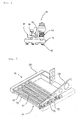
- Fig 1 is a perspective diagram showing an apparatus for processing a substrate according to this invention as viewed from the left
- Fig 2 is a perspective diagram showing the above described apparatus for processing a substrate as viewed from the right.
- an apparatus for processing a substrate 10 is mainly formed of a portion for mounting a substrate 1, where a fragile substrate is mounted, a portion for conveying a substrate 2, having a number of robots for conveying a substrate, a scribing portion 3, which scribes a substrate that has been conveyed by portion for conveying a substrate 2, and a breaking portion 4 for breaking a scribed substrate.
- a cassette 11 for conveying a substrate is supplied in the direction of arrow A in the figure, and is carried by a conveyor 12 to the front of a sucking hand 14.
- cassette 11 a number of small mother substrates, in which two glass plates are bonded together, are aligned so that the faces become parallel to each other in a state where the shorter sides thereof stand approximately vertically.
- small mother substrates in stripe form that have been divided from a mother substrate (for example, 2 m ⁇ 1 m) and of which the longer sides do not exceed 1 m, for example, glass substrates of 670 mm ⁇ 100 mm ⁇ 0.7 mm, are used.
- sucking hand 14 sucks substrates one by one and transfers them to a support 15 from cassette 11 that has been carried to the rear-end portion of conveyor 12.
- This operation is repeated, for example, five times, and thereby, five substrates, which are small mother substrates, are mounted on support 15 in line with the main surfaces thereof being parallel to the main surface of the support 15.
- Positioning members 16 are placed on support 15, and thereby, small mother substrates are positioned at predetermined positions on support 15.
- empty cassette 11 is conveyed in the direction of arrow B in the figure by conveyor 13.
- Portion for sucking the upper surface of a substrate 21 sucks and supports five small mother substrates in line at the same time, moves them to a scribing table 31 and mounts the small mother substrates on scribing table 31.
- another set of five small mother substrates is mounted so as to be in line on support 15 by means of sucking hand 14.
- a scribe line is drawn on surface A, which is one surface of a small mother substrate.
- a configuration where a single or a number of scribe heads having a wheel cutter for scribing are provided can be adopted for scribing table 31.
- the table it is preferable for the table to be of a rotational system or for the scribe heads to be of a rotational system so that scribe lines can be drawn in two directions which are perpendicular to each other on the table.
- the wheel cutters for scribing glass wheel cutters of Japanese Patent No 3074143 are preferable.
- Robot for conveying a substrate 24 moves to scribing table 31 along the top of guide rail 20.
- Robot for conveying a substrate 24 has a portion for turning over and sucking a substrate 23, which supports a small mother substrate of which the main surface is sucked by a number of sucking surfaces that turn over 180° upside down almost simultaneously.
- Figs 3 and 4 are a plan diagram and a side diagram showing portion for turning over and sucking a substrate 23.
- the configuration of portion for turning over and sucking a substrate 23 is described in reference to Figs 3 and 4.
- Portion for turning over and sucking a substrate 23 is provided with a rotational support 51, a rotational axis 52 in pipe form and a number of sucking bellows 60 which form a sucking surface.
- Rotational support 51 has a number of holes 51 a on the surface and is supported by rotational axis 52 via a support 54 having elasticity. Holes 51a in rotational support 51 connect to sucking bellows 60 on the rear surface.
- Rotational axis 52 has holes 55 which are dispersed in the longitudinal direction and is connected to the below described portion for driving the rotation, which is placed at one end of the axis. Both ends of rotational axis 52 are connected to a vacuum source, not shown, via rotary joints 56. Holes 55 of rotational axis 52 connect to holes 51a of rotational support 51 via a tube 58 and an electromagnetic valve 57. When the above described vacuum source is driven, electromagnetic valve 57 is switched, and thereby, it becomes possible to suck a substrate using arbitrary sucking bellows 60. That is to say, it is possible to switch the dimensions of the sucking surface depending on the size of the substrate.
- Fig 5 is a perspective diagram showing the arrangement of portion for turning over and sucking a substrate 23 in robot for conveying a substrate 24.
- Portion for turning over and sucking a substrate 23 is attached to robot for conveying a substrate 24, which can move along the top of guide rail 20 as described above, and has a number of rotational supports 51 with a sucking face which sucks and holds each substrate from a main surface.
- Rotational supports 51 are respectively supported by a rotational axis 52, and both ends of these rotational axes 52 are supported by a frame 59.
- Rotational axes 52 are parallel to each other, extend in the longitudinal direction of rotational support 51 and pass through approximately the center portion of each rotational support 51 in the width in the direction perpendicular to the longitudinal direction.
- Portion for driving the rotation made of cylinders 75 and racks and pinions 76, is attached to frame 59.
- One end of rotational axes 52 is supported by frame 59 so as to be rotatable, and the other end is connected to each cylinder 75 via rack and pinion 76.
- Cylinders 75 are connected to a control portion, not shown. This control portion controls the angle of rotation and the direction of rotation of rotational axes 52 via the above described portion for driving the rotation.
- Figs 6(a) to 6(d) are perspective diagrams illustrating the operation of robot for conveying a substrate 24 and portion for turning over and sucking a substrate 23.
- the operation of portion for turning over and sucking a substrate 23 is further described.
- Robot for conveying a substrate 26 has a portion for sucking the upper surface of a substrate 25, which sucks the upper surface of a substrate and holds the substrate.
- Robot for conveying a substrate 24 and robot for conveying a substrate 26 are formed so that they can intersect on top of guide rail 20.
- Portion for sucking the upper surface of a substrate 25 of robot for conveying a substrate 26 receives a substrate that is sucked and held by portion for turning over and sucking a substrate 23 of robot for conveying a substrate 24, and then, robot for conveying a substrate 24 retreats while robot for conveying a substrate 26 moves down onto the surface of positioning table 33, where suction of portion for sucking the upper surface of a substrate 25 is released so that the substrate is mounted on positioning table 33.
- Positioning tale 33 has a positioning member 34 as a positioning mechanism for positioning a mounted substrate in a predetermined place on this table. Positioning member 34 positions a mounted substrate in a predetermined place on positioning table 33.
- robot for conveying a substrate 26 holds a substrate by sucking the upper surface of a substrate that has been positioned on the surface of table 33 by means of portion for sucking the upper surface of a substrate 25, moves to a second scribing table 35 and mounts the substrate on scribing table 35. It is possible to adopt a configuration having a single or a number of scribe heads with a wheel cutter for scribing for scribing table 35.
- the table is of a rotational type, or for the scribe heads to be of a rotational type, so that scribe lines can be drawn in two perpendicular directions on the table.
- the wheel cutter for scribing the glass wheel cutter of Japanese Patent No. 3074143 is preferable.
- a scribe line is drawn on surface B, which is the upper surface of a substrate, on scribing table 35.
- the substrate becomes of an approximately divided state. That is to say, unit substrates where cracking that has been caused through the drawing of scribe lines completely reaches the rear surface of the substrate and unit substrates where such cracking does not completely reach the rear surface of the substrates but stops in the middle in the direction of the thickness of the substrate are mixed.
- robot for conveying a substrate 28 moves to scribing table 35, and then, a substrate where a scribing line is drawn is held though suction of the upper surface by means of portion for sucking the upper surface of a substrate 27, and moves to a breaking conveyor 41 along the top of guide rail 20.
- the above described portion for sucking the upper surface of a substrate 27 is provided with a sucking surface made of a porous member.
- the porous member it is possible to use a porous material or a member that has been made porous for the porous member, and plastic foam having continuous bubbles, rubber foam, a sintered metal, knitted paper or a combination of these can be used.
- the amount of leakage of air from the above described sucking surface is relatively small, making suction of a substrate possible when such a porous sucking face is provided. Accordingly, substrates of different sizes can be sucked and turned over.
- Use of a sucking surface made of a porous member makes it possible to suck a substrate even in the case where the area of the sucking surface of portion for turning over and sucking a substrate 23 is greater than the area of contact of a substrate that makes contact with the above described sucking surface. Accordingly, even when the dimensions of the substrates change, the substrates can be treated flexibly.
- Fig 7 is a plan diagram showing the configuration of a breaking portion 4.
- Breaking portion 4 is provided with conveyor belts 41, 42 and 43 as well as breaking members 44 and 45 which are members for pressing a substrate which are placed at both ends of conveyor belt 41 in the direction of conveyance.
- Conveyor belt 41 is formed of one belt
- conveyor belt 42 is formed of two belts which can be translated in the direction of the arrows in the figure
- conveyor belt 43 is formed of three belts.
- Robot for conveying a substrate 28 which has moved onto conveyor belt 41 releases the suction of portion for sucking the upper surface of a substrate 27 so as to mount a substrate onto conveyor belt 41.
- Conveyor belt 41 conveys a substrate toward the upper stream side (leftwards in the figure) and drops a substrate from conveyor belt 41 by pushing an edge portion (unnecessary portion) on one end side of the substrate from the top with breaking member 44, which is placed on the upper stream side in the line configuration of apparatus for processing a substrate 10 which processes a substrate starting from scribing to breaking.
- conveyor belt 41 is driven so that the direction of conveyance of the belt points toward the lower stream side in the above described line configuration and conveys a substrate from which the edge portion on one end side has been removed toward the lower stream side (rightwards in the figure).
- breaking member 45 which is placed on the lower stream side pushes the edge portion on the other end side of a substrate from the top so as to drop the substrate between the two belts of conveyor belt 42 in an opening state.
- the state is changed so that the two belts of conveyor belt 42 are close to each other (state in the figure) and breaking member 45 pushes the portion on one end side of a substrate in strip form so that the substrate is completely divided into unit substrates and sequentially drops the unit substrates onto the two belts of conveyor belt 42 in a state of being close to each other.
- the divided unit substrates are conveyed by conveyor belt 42 and then by conveyor belt 43 and then are conveyed to the next process.
- a substrate which is sucked by portion for turning over and sucking a substrate 23 is a small mother substrate which has been divided from a mother substrate and is the substrate in strip form
- the above described operation can be applied to an original mother substrate in the case where a mother substrate has a width that is smaller than the length and width of rotational support 51. That is to say a mother substrate can be sucked by the portion for turning over and sucking a substrate without undergoing the process of dividing the substrate into pieces in strip form in advance.
- a substrate that is sucked by portion for turning over and sucking a substrate 23 may be a mother substrate in a state where a scribe line is partially formed in advance but the substrate is not completely separated.
- a substrate to be rotated by the suction member it is practically preferable for a substrate to be rotated by the suction member to have a longitudinal side which does not exceed 1 m and a thickness which does not exceed 1.5 mm.
- the area for installation of the apparatus that is required for the rotation can be reduced and the occurrence of warping in a substrate can be minimized.
- the apparatus for processing a substrate according to the second embodiment of this invention is described in reference to Figs 8 to 10.
- the distance between axis lines of the rotational axis of adjacent suction members is constant in robot for conveying a substrate 24 has suction members so that substrates which are placed on a table in advance at intervals which agree with the distance between the axis lines are sucked and turned over
- an example of a robot for conveying a substrate having a configuration where the distance between the axis lines of the rotational axis of adjacent suction members is varied in accordance with the intervals of substrates which are mounted on a table in advance and then the substrates which are mounted on the table are sucked and turned over is described.
- a portion for turning over and sucking a substrate 70 has a frame 79 having a side plate 77a and a side plate 77b, rotational supports 73 of which the axes are supported by frame 79 via rotational axes 72, rack pinion 76 made of a pinion and a rack and a cylinder 75 and is formed of a portion for driving a rotational axis which rotates rotational axes 72 of rotational supports 73 and a portion for shifting a rotational axis which varies the distance between axis lines of adjacent rotational axes 72 before or at the time when rotational axes 72 are rotated.
- Frame 79, rotational supports 73 and the portion for driving a rotational axis have the same configurations as those in the first embodiment, and therefore, the descriptions thereof are omitted.
- a pair of rails 90 which are above and below parallel to each other are placed in the lower portions of the outer sides of side plate 77a and side plate 77b of frame 79.
- a number of bases 91 are attached between rails 90 so as to be slidable along rails 90 in the leftward and rightward directions.
- the above described rack 76b and a cylinder 75 are secured to each base 91 and a hole 91a through which a rotational axis 72 penetrates so as to be rotatable is provided.
- each of rotational axes 72 of rotational supports 73 (73a to 73d ...73n) are inserted into long holes 79a which are respectively provided on the two sides of frame 79 so as to be movable.
- One end of each rotational axis 72 penetrates through hole 91a which is provided in a base 91 and has a pinion 76a attached thereto.
- a pinion gear 76a is engaged to the above described rack 76b which is secured to base 91.
- Rotational supports (73a to 73d ... 73n), rack pinion 76 made of pinion 76a and rack 76b, cylinder 75 and base 91 form a movable unit.
- rack 76b and cylinder 75 which engage rotational support 73a on the left in the figure via rotational axis 72 and pinion 76a are not secured to base 91, but secured to frame 79.
- linking mechanism 98 in pantograph form which expands and contracts in one direction.
- a node 94 at one end of linking mechanism 98 in the longitudinal direction in the figure is secured to cylinder 75 on the left in the figure (that is to say, is secured to frame 79).
- a node 92 at the other end is secured to one end portion of a rod 96 of cylinder 95 (cylinder for linking mechanism 98) that is secured to frame 79.
- Other nodes 93 of linking mechanism 98 are connected to cylinders 75, which are secured to the top of base 91 (that is to say, secured to base 91). Cylinder 95 can shift rod 96 in the direction of the arrows in the figure.
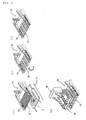
- the apparatus for processing a substrate according to the third embodiment of this invention is described in reference to Figs 11 to 14.
- an apparatus for separating a substrate, which separates a substrate along a scribe line is described as a modification which uses a robot for conveying a substrate 70 having a leaking mechanism 98 in pantograph form as described in the second embodiment.
- the third embodiment an example of a configuration which has a number of rotational axes to which suction members are attached, a portion for driving a rotational axis, which is the same as those used in the above described first and second embodiments, a frame to which the portion for driving a rotational axis and the number of rotational axes are attached so that the rotational axes can be rotated by the portion for driving a rotational axis, at least one suction member unit formed of a portion for shifting a rotational axis, which changes the distance between axis lines of the number of rotational axes that are attached to the frame, and a unit supporting portion for supporting a number of suction member units, which are the same as the above described suction member unit, in such a manner that these can approach and retreat from each other, and where a mother substrate is separated into unit substrates by means of the suction member through the operation of the portion for shifting a rotational axis, is described.
- an apparatus for separating a substrate 100 has a number of rotational axes 101 to which suction members 103a to 103f are attached, a portion for driving a rotational axis 102 and frames 110 and 120 to which the number of rotational axes 101 and portion for driving a rotational axis 102 are attached so that rotational axes 101 can be rotated by portion for driving a rotational axis 102.
- the portion for driving a rotational axis 102 has a rack pinion made of a pinion and a rack, and a cylinder 75 as a portion for driving a rotational axis which rotates rotational axes 101.
- Portions for shifting a rotational axis 104 which change the distance between axis lines of the number of rotational axes 101, are attached to a side plate 110a and a side plate 110b ,which face each other in frame 110, as well as a side plate 120a and a side plate 120b, which face each other in frame 120 (here, Fig 11 does not show the portions for shifting a rotational axis which are attached to side plates 110a, 110b and 120b), and thereby, suction member units 130 and 140 are formed.
- Suction member units 130 and 140 are respectively supported by a pair of portions for supporting a unit 150 that are provided on the outside of side plates 110c and 120c, which do not face each other, of suction member units 130 and 140.
- Portions for supporting a unit 150 are made of a bowl nut portion 151, a driving portion 152 and a bowl screw 153, which are attached to the outside of side plates 110c and 120c of suction member units 130 and 140, and support suction member units 130 and 140 in such a manner that support suction member units 130 and 140 can approach and retreat from each other in the direction of the arrows in the figure.
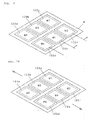
- Figs 12(A) to 12(D) are diagrams schematically showing the configuration of a mother substrate M for a liquid crystal panel which is made of two glass substrates, a TFT substrate and a CF (color filter) substrate, bonded together, and the process for separating mother substrate M into unit substrates.
- Fig 12(A) is a plan diagram showing mother substrate M for a liquid crystal panel.
- Mother substrate M has a sealant Z, which is located between two glass substrates for bonding them together, and in which an injection hole P, through which liquid crystal is injected into a gap surrounded by sealant Z, is provided.
- Fig 12(B) is a side diagram showing a state where scribe lines are drawn on the surfaces of the two glass substrates in order to gain six unit substrates W from mother substrate M.
- the method for drawing a scribe line on mother substrate M for a liquid crystal panel, which is formed of two glass substrates bonded together may be any method such as a method using a cutter wheel or a method using laser scribing, it is preferable to use the method that is disclosed, for example, in Japanese Patent No. 3042192.
- Fig 12(C) shows a state where the substrate is broken using a breaking apparatus along the scribe lines that have been drawn as shown in Fig 12(B). After this breaking process, mother substrate M is separated into unit substrates W as described below.
- Fig 12(D) is a diagram schematically showing the process of separating mother substrate M into unit substrates W.
- Mother substrate M for a liquid crystal panel is mounted so that the TFT substrate makes contact with the table, and the CF (color filter) substrate, which has the display surface, faces upwards.
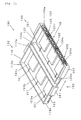
- Figs 13 and 14 are diagrams showing the steps of the operation for separating mother substrate M into unit substrates W using the apparatus for separating a substrate 100.
- the portion for shifting a rotational axis 104 (which is the same as the portion for shifting a rotational axis of Fig 9) is made to operate so that the respective intervals between w1 and w3, between w3 and w5, between w2 and w4 as well as between w4 and w6 coincide with the distance between the actual lines of rotational axes 101.
- the pair of portions for supporting a unit 150 are made to operate so that the respective intervals between w1 and w2, w3 and w4 as well as w5 and w6 coincide with the gap between suction member units 130 and 140.
- respective suction members 103a to 103f of the apparatus for separating a substrate 100 are lowered from the place above mother substrate M, which is mounted onto the table, so as to suck and be secured to mother substrate M in the locations of unit substrates W.
- respective suction members 103a to 103f of the apparatus for separating a substrate 100, which have sucked mother substrate M are raised off the table and are stopped.
- the portions for shifting a rotational axis 104 are made to operate so as to change the distance between the axis lines of rotational axes 101 of suction members 103a through 103f.
- suction member 103a and suction member 103b stay secured and the axis line of the respective rotational axes 101 do not change, and suction member 103b and suction member 103c as well as suction member 103e and suction member 103f move by equal distance in the directions of the arrows in Fig 13.
- mother substrate M is separated into three pieces with one made of w1 and w2, one made of w3 and w4, and one made of w5 and w6.
- the pair of portions for supporting a unit 150 are made to operate so as to change the gap between suction member unit 130 and suction member unit 140. That is to say, suction members 103a to 103c and suction members 103d to 103f move away from each other in the directions shown by the arrows in the figure.
- the piece made of w1 and w2, the piece made of w3 and w4, and the piece made of w5 and w6 are respectively separated so as to be six unit substrates W, including w1 to w6.
- Cut out members Q1 in the periphery portion of mother substrate M (Q1 have been in a state of almost being cut) are automatically detached so as to drop when the above described suction members 103a to 103f move in the two directions, longitudinal and lateral directions. Only unit substrates W remain on respective suction members 103a to 103f of suction member unit 130 and suction member unit 140 in a state of being sucked. These unit substrates W are conveyed in the state they are in or in a state where respective suction members 103a to 103f have been turned over through the operation of the portions for driving a rotational axis 102 so that unit substrates W are appropriately positioned for the next process.
- unnecessary members Q2 and the like between unit substrates W are detached from mother substrate M so as to drop by their own weight (unnecessary members which cannot be detached may be made to drop by a pressing means, if necessary) when the above described suction members 103a to 103f move in the two directions, longitudinal and lateral directions, and therefore, only unit substrates W can be made to remain on respective suction members 103a to 103f of suction member units 130 and 140 in a state of being sucked.
- respective suction members 103a to 103f which have sucked the regions of unit substrates W of a mother substrate M, can be moved by an arbitrary distance in the two actual directions, and therefore, unnecessary members Q2 can be removed and dropped.
- unnecessary members Q2 such as middle margins are removed in a state where the CF substrate having the display side for a liquid crystal panel is placed on the upper side so as not to make contact with the table, and therefore, the CF substrate can be prevented from being damaged.
- a rack pinion 76 made of a pinion and a rack, and a cylinder 75 are used as a portion for driving a rotational axis which rotates a rotational axis 72 of a rotational support 73
- a configuration, where a servo motor having a gear head is connected to a rotational axis 72, can be used instead of the above.
- a linking mechanism 98 in a pantographic system is used in the portions for shifting a rotational axis so as to provide a configuration where a number of moveable units formed of a rotational support (73b, 73 c, 73d, ...73n), a rack pinion 76 made of a pinion 76a and a rack 76b, a cylinder 75 and a base 91can be moved simultaneously, each of these moveable units may be individually synchronized with and moved by a servo motor in the configuration.
- a first processing step is carried out on surface A, which is one surface of a substrate
- the substrate where a predetermined process has been carried out on the main surface is sucked and held from the main surface using a number of suction members, each of which is provided with a suction surface, and the above described suction members are sequentially or approximately simultaneously rotated, and thereby, the two main surfaces of the above described substrate are turned over in the upward and downward directions, and then, a second processing step is carried out on surface B, which is the other surface of the substrate.
- the robot for conveying a substrate 70 which is described in the above second embodiment
- the apparatus for separating a substrate 100 which is described in the above third embodiment
- the present invention can be used for a substrate process on, for example, a substrate or the like that is used for a liquid crystal display panel.
Landscapes
- Chemical & Material Sciences (AREA)
- Engineering & Computer Science (AREA)
- Materials Engineering (AREA)
- Organic Chemistry (AREA)
- Physics & Mathematics (AREA)
- Nonlinear Science (AREA)
- Crystallography & Structural Chemistry (AREA)
- General Physics & Mathematics (AREA)
- Optics & Photonics (AREA)
- Re-Forming, After-Treatment, Cutting And Transporting Of Glass Products (AREA)
- Container, Conveyance, Adherence, Positioning, Of Wafer (AREA)
- Processing Of Stones Or Stones Resemblance Materials (AREA)
Applications Claiming Priority (2)
| Application Number | Priority Date | Filing Date | Title |
|---|---|---|---|
| JP2003436226 | 2003-12-04 | ||
| PCT/JP2004/018048 WO2005053925A1 (ja) | 2003-12-04 | 2004-12-03 | 基板加工方法、基板加工装置および基板搬送方法、基板搬送機構 |
Publications (1)
| Publication Number | Publication Date |
|---|---|
| EP1690660A1 true EP1690660A1 (en) | 2006-08-16 |
Family
ID=34650732
Family Applications (1)
| Application Number | Title | Priority Date | Filing Date |
|---|---|---|---|
| EP20040819939 Withdrawn EP1690660A1 (en) | 2003-12-04 | 2004-12-03 | Substrate machining method, substrate machining device, substrate carrying method, and substrate carrying mechanism |
Country Status (7)
| Country | Link |
|---|---|
| US (2) | US20080190981A1 (enExample) |
| EP (1) | EP1690660A1 (enExample) |
| JP (1) | JP4739024B2 (enExample) |
| KR (1) | KR101211428B1 (enExample) |
| CN (1) | CN1890074B (enExample) |
| TW (1) | TW200521095A (enExample) |
| WO (1) | WO2005053925A1 (enExample) |
Cited By (1)
| Publication number | Priority date | Publication date | Assignee | Title |
|---|---|---|---|---|
| EP2147899A1 (en) * | 2008-07-18 | 2010-01-27 | Mitsuboshi Diamond Industrial Co., Ltd. | Method for processing terminal in bonded substrate |
Families Citing this family (56)
| Publication number | Priority date | Publication date | Assignee | Title |
|---|---|---|---|---|
| EP1741527A1 (en) * | 2004-03-15 | 2007-01-10 | Mitsuboshi Diamond Industrial Co., Ltd. | Substrate dividing system, substrate manufacturing equipment, substrate scribing method and substrate dividing method |
| KR20070023958A (ko) * | 2005-08-25 | 2007-03-02 | 삼성전자주식회사 | 액정 표시 장치용 기판 절단 시스템 및 상기 시스템을이용한 액정 표시 장치용 기판 절단 방법 |
| JP4904036B2 (ja) * | 2005-09-15 | 2012-03-28 | 三星ダイヤモンド工業株式会社 | 基板分断システム |
| KR100853989B1 (ko) * | 2007-06-20 | 2008-08-25 | 주식회사 휘닉스 디지탈테크 | 셀 분리 장치 및 방법 |
| KR100809043B1 (ko) * | 2007-06-20 | 2008-03-03 | 주식회사 휘닉스 디지탈테크 | 태그 분리 모듈 및 방법 |
| US20090223628A1 (en) * | 2008-03-07 | 2009-09-10 | Semiconductor Energy Laboratory Co., Ltd. | Manufacturing apparatus of composite substrate and manufacturing method of composite substrate with use of the manufacturing apparatus |
| CN102976599B (zh) * | 2008-04-21 | 2015-06-24 | 塔工程有限公司 | 对结合基板进行台阶式划线的方法及其控制系统 |
| CN102057314B (zh) * | 2008-06-18 | 2012-03-28 | 三星钻石工业股份有限公司 | 基板加工系统 |
| TW201008887A (en) * | 2008-06-25 | 2010-03-01 | Mitsuboshi Diamond Ind Co Ltd | Scribing apparatus |
| JP5312857B2 (ja) * | 2008-06-30 | 2013-10-09 | Towa株式会社 | 基板の切断方法及び装置 |
| KR101160166B1 (ko) * | 2008-11-05 | 2012-06-28 | 세메스 주식회사 | 절단 장치용 이송 유닛, 이를 갖는 절단 장치 및 이를 이용한 절단 방법 |
| US20100195083A1 (en) * | 2009-02-03 | 2010-08-05 | Wkk Distribution, Ltd. | Automatic substrate transport system |
| TWI436831B (zh) * | 2009-12-10 | 2014-05-11 | Orbotech Lt Solar Llc | 真空處理裝置之噴灑頭總成 |
| KR101228966B1 (ko) * | 2010-06-14 | 2013-02-01 | (주)성현 테크놀로지 | 평판소재 가공방법, 가공장치 및 이에 적용되는 평판소재 |
| US8459276B2 (en) | 2011-05-24 | 2013-06-11 | Orbotech LT Solar, LLC. | Broken wafer recovery system |
| JP2013023401A (ja) * | 2011-07-20 | 2013-02-04 | Mitsuboshi Diamond Industrial Co Ltd | 分断装置 |
| JP5348212B2 (ja) * | 2011-09-02 | 2013-11-20 | 三星ダイヤモンド工業株式会社 | 分断装置 |
| JP5353978B2 (ja) * | 2011-09-05 | 2013-11-27 | 三星ダイヤモンド工業株式会社 | 分断装置 |
| EP2754524B1 (de) | 2013-01-15 | 2015-11-25 | Corning Laser Technologies GmbH | Verfahren und Vorrichtung zum laserbasierten Bearbeiten von flächigen Substraten, d.h. Wafer oder Glaselement, unter Verwendung einer Laserstrahlbrennlinie |
| JP6126396B2 (ja) * | 2013-02-07 | 2017-05-10 | 三星ダイヤモンド工業株式会社 | 基板加工装置 |
| JP6059565B2 (ja) | 2013-03-13 | 2017-01-11 | 三星ダイヤモンド工業株式会社 | 吸着反転装置 |
| EP2781296B1 (de) | 2013-03-21 | 2020-10-21 | Corning Laser Technologies GmbH | Vorrichtung und verfahren zum ausschneiden von konturen aus flächigen substraten mittels laser |
| JP6105414B2 (ja) * | 2013-07-08 | 2017-03-29 | 三星ダイヤモンド工業株式会社 | 貼り合わせ基板の加工装置 |
| JP5566511B2 (ja) * | 2013-08-07 | 2014-08-06 | 三星ダイヤモンド工業株式会社 | 分断装置 |
| JP6280332B2 (ja) | 2013-09-09 | 2018-02-14 | 三星ダイヤモンド工業株式会社 | 基板反転搬送装置 |
| US9517963B2 (en) | 2013-12-17 | 2016-12-13 | Corning Incorporated | Method for rapid laser drilling of holes in glass and products made therefrom |
| US11556039B2 (en) | 2013-12-17 | 2023-01-17 | Corning Incorporated | Electrochromic coated glass articles and methods for laser processing the same |
| US20150165560A1 (en) | 2013-12-17 | 2015-06-18 | Corning Incorporated | Laser processing of slots and holes |
| KR101535136B1 (ko) * | 2014-06-11 | 2015-07-14 | 한국미쯔보시다이아몬드공업(주) | 기판 절단 장치 및 기판 절단 장치에서의 기판 반송 방법 |
| JP6357914B2 (ja) * | 2014-06-26 | 2018-07-18 | 三星ダイヤモンド工業株式会社 | スクライブ装置 |
| KR102445217B1 (ko) | 2014-07-08 | 2022-09-20 | 코닝 인코포레이티드 | 재료를 레이저 가공하는 방법 및 장치 |
| LT3169477T (lt) | 2014-07-14 | 2020-05-25 | Corning Incorporated | Skaidrių medžiagų apdorojimo sistema ir būdas, naudojant lazerio pluošto židinio linijas, kurių ilgis ir skersmuo yra reguliuojami |
| TWI558223B (zh) * | 2014-12-19 | 2016-11-11 | Concraft Holding Co Ltd | Production method of sound net assembly |
| JP7292006B2 (ja) | 2015-03-24 | 2023-06-16 | コーニング インコーポレイテッド | ディスプレイガラス組成物のレーザ切断及び加工 |
| CN104808370B (zh) * | 2015-05-22 | 2017-10-31 | 合肥京东方光电科技有限公司 | 一种对盒设备、对位方法 |
| JP6524803B2 (ja) * | 2015-06-02 | 2019-06-05 | 三星ダイヤモンド工業株式会社 | ブレイクシステム |
| US11186060B2 (en) | 2015-07-10 | 2021-11-30 | Corning Incorporated | Methods of continuous fabrication of holes in flexible substrate sheets and products relating to the same |
| CN105548211B (zh) * | 2015-12-29 | 2019-02-19 | 芜湖东旭光电科技有限公司 | 玻璃基板划伤缺陷的产生位置的查找方法 |
| SG11201809797PA (en) | 2016-05-06 | 2018-12-28 | Corning Inc | Laser cutting and removal of contoured shapes from transparent substrates |
| CN109803786B (zh) | 2016-09-30 | 2021-05-07 | 康宁股份有限公司 | 使用非轴对称束斑对透明工件进行激光加工的设备和方法 |
| US11542190B2 (en) | 2016-10-24 | 2023-01-03 | Corning Incorporated | Substrate processing station for laser-based machining of sheet-like glass substrates |
| JP6271683B2 (ja) * | 2016-11-17 | 2018-01-31 | 三星ダイヤモンド工業株式会社 | 吸着反転装置 |
| JP6838373B2 (ja) * | 2016-12-02 | 2021-03-03 | 日本電気硝子株式会社 | 板ガラスの製造方法及び板ガラスの折割装置 |
| JP6878117B2 (ja) * | 2017-04-25 | 2021-05-26 | 川崎重工業株式会社 | シート搬送装置及びシート搬送方法 |
| CN107140818B (zh) * | 2017-06-28 | 2020-02-14 | 重庆华瑞玻璃有限公司 | 一种条状玻璃切割机 |
| JP6941405B2 (ja) * | 2017-08-21 | 2021-09-29 | 株式会社ディスコ | 分割方法 |
| KR102114025B1 (ko) * | 2018-01-30 | 2020-05-25 | 주식회사 탑 엔지니어링 | 기판 절단 장치 |
| JP7085743B2 (ja) * | 2018-01-31 | 2022-06-17 | 三星ダイヤモンド工業株式会社 | 基板反転装置 |
| CN112262620B (zh) * | 2018-06-13 | 2022-06-17 | 株式会社富士 | 对基板作业机 |
| KR102052901B1 (ko) * | 2018-11-30 | 2019-12-11 | (주)에프피에이 | 다관절 로봇을 이용한 fpcb 밴딩 부착 장치 |
| CN109387963A (zh) * | 2018-12-21 | 2019-02-26 | 深圳市华星光电技术有限公司 | 裂片吸附载台及液晶面板的切割裂片方法 |
| JP2021067797A (ja) * | 2019-10-23 | 2021-04-30 | 日本電気硝子株式会社 | 板状部材の製造方法、板状部材の中間体及び板状部材 |
| CN111646684A (zh) * | 2020-05-25 | 2020-09-11 | 彩虹集团(邵阳)特种玻璃有限公司 | 一种盖板玻璃分切设备用顶断装置及其工作方法 |
| CN114590619B (zh) * | 2020-12-07 | 2024-08-13 | Nps株式会社 | 膜加工系统 |
| CN114311094B (zh) * | 2021-12-31 | 2023-10-20 | 福建晟哲自动化科技有限公司 | 一种液晶面板的切裂翻片机 |
| CN115533537B (zh) * | 2022-08-26 | 2024-11-26 | 天通日进精密技术有限公司 | 一种具有上下料翻转组件的开磨一体机 |
Family Cites Families (12)
| Publication number | Priority date | Publication date | Assignee | Title |
|---|---|---|---|---|
| US3862749A (en) * | 1974-01-30 | 1975-01-28 | Af Ind | Metal slab conditioning system |
| GB1536137A (en) * | 1975-03-06 | 1978-12-20 | Pilkington Brothers Ltd | Methods and apparatus for separating glass sheets into separate sheet portions |
| JPH0353546A (ja) * | 1989-07-21 | 1991-03-07 | Mitsubishi Electric Corp | 半導体装置の製造方法およびその製造装置 |
| JPH0625246U (ja) * | 1992-08-29 | 1994-04-05 | 村田機械株式会社 | 板材の反転機 |
| US5855468A (en) * | 1995-12-22 | 1999-01-05 | Navistar International Transportation Corp. | Method and apparatus for setting foundry core assemblies |
| JPH11116260A (ja) * | 1997-10-08 | 1999-04-27 | Mitsuboshi Diamond Kogyo Kk | ガラス加工装置 |
| JP4046302B2 (ja) * | 1998-06-02 | 2008-02-13 | 三菱電機エンジニアリング株式会社 | ワーク加工装置及びそのワーク反転装置 |
| DE19950068B4 (de) * | 1999-10-16 | 2006-03-02 | Schmid Technology Systems Gmbh | Verfahren und Vorrichtung zum Vereinzeln und Ablösen von Substratscheiben |
| JP4402883B2 (ja) * | 2001-01-17 | 2010-01-20 | 三星ダイヤモンド工業株式会社 | 分断装置および分断システム並びに分断方法 |
| JP4038431B2 (ja) * | 2001-03-16 | 2008-01-23 | 三星ダイヤモンド工業株式会社 | スクライブ方法及びカッターホィール並びにそのカッターホィールを用いたスクライブ装置、そのカッターホィールを製造するカッターホィール製造装置 |
| JP2004055860A (ja) * | 2002-07-22 | 2004-02-19 | Renesas Technology Corp | 半導体装置の製造方法 |
| JP4197129B2 (ja) * | 2003-03-19 | 2008-12-17 | シャープ株式会社 | ワーク搬送装置 |
-
2004
- 2004-12-03 JP JP2005515994A patent/JP4739024B2/ja not_active Expired - Fee Related
- 2004-12-03 WO PCT/JP2004/018048 patent/WO2005053925A1/ja not_active Ceased
- 2004-12-03 US US10/581,557 patent/US20080190981A1/en not_active Abandoned
- 2004-12-03 CN CN2004800356523A patent/CN1890074B/zh not_active Expired - Fee Related
- 2004-12-03 EP EP20040819939 patent/EP1690660A1/en not_active Withdrawn
- 2004-12-06 TW TW93137738A patent/TW200521095A/zh not_active IP Right Cessation
-
2006
- 2006-05-29 KR KR1020067010470A patent/KR101211428B1/ko not_active Expired - Fee Related
-
2009
- 2009-06-02 US US12/476,336 patent/US7845529B2/en not_active Expired - Fee Related
Non-Patent Citations (1)
| Title |
|---|
| See references of WO2005053925A1 * |
Cited By (1)
| Publication number | Priority date | Publication date | Assignee | Title |
|---|---|---|---|---|
| EP2147899A1 (en) * | 2008-07-18 | 2010-01-27 | Mitsuboshi Diamond Industrial Co., Ltd. | Method for processing terminal in bonded substrate |
Also Published As
| Publication number | Publication date |
|---|---|
| JPWO2005053925A1 (ja) | 2007-06-28 |
| CN1890074B (zh) | 2011-03-30 |
| US20080190981A1 (en) | 2008-08-14 |
| US20090236384A1 (en) | 2009-09-24 |
| WO2005053925A1 (ja) | 2005-06-16 |
| TWI342301B (enExample) | 2011-05-21 |
| CN1890074A (zh) | 2007-01-03 |
| KR101211428B1 (ko) | 2012-12-18 |
| KR20060123211A (ko) | 2006-12-01 |
| JP4739024B2 (ja) | 2011-08-03 |
| US7845529B2 (en) | 2010-12-07 |
| TW200521095A (en) | 2005-07-01 |
Similar Documents
| Publication | Publication Date | Title |
|---|---|---|
| US7845529B2 (en) | Method for processing substrate, apparatus for processing substrate, method for conveying substrate and mechanism for conveying substrate | |
| US7131562B2 (en) | Scribing and breaking apparatus, system therefor, and scribing and breaking method | |
| CN102057314B (zh) | 基板加工系统 | |
| JP4464961B2 (ja) | 基板分断システム、基板製造装置、基板スクライブ方法および基板分断方法 | |
| JP4131853B2 (ja) | 表示装置の製造方法及び製造装置 | |
| US7878381B2 (en) | Plate material cutting unit, plate material cutting apparatus equipped with the plate material cutting unit, and plate material cutting system equipped with the plate material cutting apparatus | |
| JP4996703B2 (ja) | 基板分断装置 | |
| EP1475357B1 (en) | Fragile material substrate parting system | |
| CN101439926B (zh) | 划线装置和方法以及利用该装置和方法的基板切断装置 | |
| WO2004096721A1 (ja) | 脆性基板分断システムおよび脆性基板分断方法 | |
| JP2010052995A (ja) | マザー基板のスクライブ方法 | |
| JP6364789B2 (ja) | スクライブ装置 | |
| TWI423861B (zh) | Glass plate grinding device | |
| KR100642902B1 (ko) | 유리기판의 절단장치 | |
| TWI495540B (zh) | The glass polishing apparatus |
Legal Events
| Date | Code | Title | Description |
|---|---|---|---|
| PUAI | Public reference made under article 153(3) epc to a published international application that has entered the european phase |
Free format text: ORIGINAL CODE: 0009012 |
|
| 17P | Request for examination filed |
Effective date: 20060503 |
|
| AK | Designated contracting states |
Kind code of ref document: A1 Designated state(s): AT BE BG CH CY CZ DE DK EE ES FI FR GB GR HU IE IS IT LI LT LU MC NL PL PT RO SE SI SK TR |
|
| DAX | Request for extension of the european patent (deleted) | ||
| STAA | Information on the status of an ep patent application or granted ep patent |
Free format text: STATUS: THE APPLICATION HAS BEEN WITHDRAWN |
|
| 18W | Application withdrawn |
Effective date: 20121217 |