EP1679249B1 - Servolenkung für ein Fahrzeug mit Vierradantrieb - Google Patents
Servolenkung für ein Fahrzeug mit Vierradantrieb Download PDFInfo
- Publication number
- EP1679249B1 EP1679249B1 EP06075030A EP06075030A EP1679249B1 EP 1679249 B1 EP1679249 B1 EP 1679249B1 EP 06075030 A EP06075030 A EP 06075030A EP 06075030 A EP06075030 A EP 06075030A EP 1679249 B1 EP1679249 B1 EP 1679249B1
- Authority
- EP
- European Patent Office
- Prior art keywords
- self
- aligning torque
- torque
- front wheel
- wheel side
- Prior art date
- Legal status (The legal status is an assumption and is not a legal conclusion. Google has not performed a legal analysis and makes no representation as to the accuracy of the status listed.)
- Ceased
Links
- 230000008859 change Effects 0.000 claims description 32
- 238000012937 correction Methods 0.000 claims description 4
- 230000005540 biological transmission Effects 0.000 description 17
- 238000010586 diagram Methods 0.000 description 8
- 230000001133 acceleration Effects 0.000 description 6
- 230000035807 sensation Effects 0.000 description 6
- 230000009467 reduction Effects 0.000 description 4
- 101000640813 Homo sapiens Sodium-coupled neutral amino acid transporter 2 Proteins 0.000 description 1
- 101000716973 Homo sapiens Thialysine N-epsilon-acetyltransferase Proteins 0.000 description 1
- 102100020926 Thialysine N-epsilon-acetyltransferase Human genes 0.000 description 1
- 230000007423 decrease Effects 0.000 description 1
- 230000006870 function Effects 0.000 description 1
- 238000012423 maintenance Methods 0.000 description 1
- 230000007246 mechanism Effects 0.000 description 1
- 238000012986 modification Methods 0.000 description 1
- 230000004048 modification Effects 0.000 description 1
Images


Classifications
-
- B—PERFORMING OPERATIONS; TRANSPORTING
- B62—LAND VEHICLES FOR TRAVELLING OTHERWISE THAN ON RAILS
- B62D—MOTOR VEHICLES; TRAILERS
- B62D6/00—Arrangements for automatically controlling steering depending on driving conditions sensed and responded to, e.g. control circuits
- B62D6/008—Control of feed-back to the steering input member, e.g. simulating road feel in steer-by-wire applications
-
- B—PERFORMING OPERATIONS; TRANSPORTING
- B62—LAND VEHICLES FOR TRAVELLING OTHERWISE THAN ON RAILS
- B62D—MOTOR VEHICLES; TRAILERS
- B62D5/00—Power-assisted or power-driven steering
- B62D5/06—Power-assisted or power-driven steering fluid, i.e. using a pressurised fluid for most or all the force required for steering a vehicle
-
- B—PERFORMING OPERATIONS; TRANSPORTING
- B62—LAND VEHICLES FOR TRAVELLING OTHERWISE THAN ON RAILS
- B62D—MOTOR VEHICLES; TRAILERS
- B62D6/00—Arrangements for automatically controlling steering depending on driving conditions sensed and responded to, e.g. control circuits
Definitions
- This invention relates to a power steering device for a four-wheel drive vehicle, which generates a steering reaction force appropriate to the variably changing front and rear driving force distribution.
- Japanese Utility Model Application Publication No.H2-43765 discloses a power steering control device for a vehicle, in which controlling is achieved by estimating the angle of a sideslip generated as the vehicle is steered based on a movement model of the vehicle using the vehicle velocity and steering angle; and determining a target value of the steering reaction force on steering wheels based on the vehicle velocity and sideslip angle so that the steering reaction force with this target value is generated.
- a self-aligning torque changes when braking/driving forces change; the change in self-aligning torque in turn causes the steering reaction force to change. Therefore, when the front and rear driving force distribution is variably controlled in a four-wheel drive vehicle, the self-aligning torque changes accordingly, resulting in the change in steering power and giving the driver an unpleasant sensation during steering. For example, when the front wheel driving force increases, the self-aligning torque on the front wheel side decreases; thus, the steering power becomes less, giving the driver an unpleasant sensation. Since such effects of the self-aligning torque are not considered in the technology of the above-mentioned patent literature, adapting the technology for a four-wheel drive vehicle poses a problem of giving the driver an unpleasant sensation during steering.
- the object of the present invention is to provide a power steering device for a four-wheel drive vehicle, capable of maintaining a sense of natural steering without causing an unpleasant sensation to the driver. This is achieved by generating an assisting force accordingly as the self-aligning torque varies when the front and rear driving force distribution is variably controlled.
- a power steering device for a four-wheel drive vehicle in which driving force from an engine is controlled to be variably distributed to front and rear wheels, comprising: a self-aligning torque estimation unit for estimating a self-aligning torque generated in a current vehicle behavior as a first self-aligning torque and for estimating a self-aligning torque that is to influence a subsequent vehicle behavior as a second self-aligning torque; a self-aligning torque change amount calculation unit for calculating a difference of the second self-aligning torque from the first self-aligning torque as a self-aligning torque change amount; and an assisting force correction unit for determining and outputting a corrected value of an assisting force to be generated for a steering operation based on the self-aligning torque change amount.
- the power steering device for a four-wheel-drive of the present invention even when the self-aligning torque changes as the distribution of the front and rear driving power is variably controlled, a corresponding assisting force is generated, maintaining a natural steering feeling without causing an unpleasant sensation to the driver.
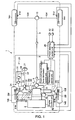
- FIG. 1 is a schematic block diagram showing the structure of a vehicle having the power steering device.
- FIG. 2 is a cross-sectional view showing the structure of a flow control valve.
- FIG. 3 is a functional block diagram of the power steering control unit.
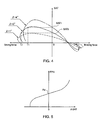
- FIG. 4 is an explanatory diagram showing the self-aligning torque against the braking/driving force for various sideslip angles.
- FIG. 5 is an explanatory diagram showing the modified steering power against the self-aligning torque change amount.
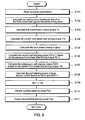
- FIG. 6 is a flow chart of the power steering control routine executed in the power steering control unit.
- reference number 1 indicates a four-wheel drive vehicle (hereinafter referred to as "vehicle"), in which the driving force from an engine 2 of the vehicle 1 is passed through a torque converter 3 and a transmission 4, and is further passed via a transmission output shaft 5 to a transfer unit 6, comprised of a hydraulic multiple disc clutch and the like, which variably controls the transfer amount.
- vehicle four-wheel drive vehicle
- the driving force that has been transmitted to the transfer unit 6 is inputted to a rear wheel final reduction gear 10 via a rear drive shaft 7, a propeller shaft 8, and a drive pinion shaft 9; meanwhile, it is also transmitted to a front wheel final reduction gear 12 via a front drive shaft 11.
- the transfer unit 6 is configured so as to variably control the distribution ratio of the driving force between the driving shafts, i.e. the front drive shaft 11 and the rear drive shaft 7, between 100:0 and 50:50, for example, by use of the control signals from a front and rear driving force distribution control unit 61.
- the front and rear driving force distribution control unit 61 is a known device.
- the amount of control is determined by including a torque sensitive torque proportional to the transmission output torque outputted from the transmission output shaft 5; a differential rotation sensitive torque proportional to the difference between an actual slippage occurring at the front and rear wheels and a target value obtained based on a theoretical vehicle model; a yaw rate feedback torque corresponding to the difference between an actual yaw rate and a target yaw rate; and various other corrections.
- the driving force entered into the rear wheel final reduction gear 10 is transmitted to a left rear wheel 14rl via a rear left wheel axle 13rl, and at the same time, it is transmitted to a right rear wheel 14rr via a rear right wheel axle 13rr.
- the driving force entered into the front wheel final reduction gear 12 is transmitted to a left front wheel 14fl via a front left wheel axle 13fl, and at the same time it is transmitted to a right front wheel 14fr via a front right wheel axle 13fr.
- Reference number 20 indicates a power steering device, which mainly comprises a steering wheel 21, a steering shaft 22 extending from the steering wheel 21, a steering gear box 23, a power steering hydraulic pressure control system 24, and a power steering control unit 25.
- a tie rod 261 is extended toward the left front wheel 14fl, while a tie rod 26r is extended toward the right front wheel 14fr.
- tie rods 261 and 26r are coupled with axle housings 281 and 28r which rotatably support the wheels 14fl and 14fr respectively via knuckle arms 271 and 27r.
- a rack shaft (not shown), which is movable in the vehicle's width direction by the rack-and-pinion mechanism via the rotation of the steering shaft 22, is placed, and on this rack shaft, a rack piston 29 is installed. Further, an assisting force for the steering force is generated, as a hydraulic pressure from the power steering hydraulic pressure control system 24 is applied to a left operation chamber 301, or to a right operation chamber 30r.
- the power steering hydraulic pressure control system 24 mainly comprises: an oil pump 31, a control valve 32, a flow control valve 33 installed in the discharge pipe between the oil pump 31 and the control valve 32, and an oil reservoir 34 for collecting oil from the oil pump 31, control valve 32, and flow control valve 33 and returning it to the oil pump 31.
- the oil pump 31 may be a vane pump driven, for example, by the engine 2, and the power steering device 20 may be that of an engine rotation rpm sensing type.
- the operating oil discharged from the oil pump 31 is adjusted to an appropriate amount according to the engine rpm by another control valve (not indicated) in the oil pump 31, and is supplied to the control valve 32 via the flow control valve 33.
- the control valve 32 is actuated by a steering operation, and a circuit of operating oil is formed according to the direction of the steering change, wherein the operating oil is supplied to the operation chambers 301/30r in the steering gear box 23 via pipes 351/35r. Thereafter, the operating oil entered into the operation chamber 301 or 30r acts on the rack piston 29, generating a pressure (assisting force) toward right or left of the rack shaft, thereby assisting and relieving the steering power. By the movement of the rack piston 29, the operating oil in the operation chamber 30r or 301 is pushed out and returned to the oil reservoir 34 via the pipe 35r or 351 and the control valve 32.
- a spool 43 in which biasing force is variably controlled by a coil spring 41 and an electromagnetic coil 42, is installed in a casing 40, and on the tip surface of the spool 43, a needle valve 44 is connected to variably control the opening of a valve passage 45 that communicates from the oil pump 31 to the control valve 32.
- a predetermined bias current A0 is constantly applied to the electromagnetic coil 42 from the power steering control unit 25. It is configured that this current varies according the sign (positive or negative) of a self-aligning torque change amount ⁇ SAT (described later), so that the amount of oil to the control valve 32 can be variably controlled.
- a distribution ratio of the driving torque (the torque distribution ratio between the front wheel side Sf and the rear wheel side Sr) from the front and rear driving force distribution control unit 61, an engine rpm Ne and an engine output torque Te from an engine control unit 62, and a turbine rotation number Nt of the torque converter 3 and a gear ratio I of the transmission 4 from a transmission control unit 63 are inputted.
- wheel speeds ⁇ fl, ⁇ fr, ⁇ rl, and ⁇ rr of the respective wheels 14fl, 14fr, 14rl, and 14rr from respective wheel speed sensors 51fl, 51fr, 51rl, and 51rr, wheel speeds ⁇ fl, ⁇ fr, ⁇ rl, and ⁇ rr of the respective wheels 14fl, 14fr, 14rl, and 14rr, from a yaw rate sensor 52 a yaw rate ⁇ that is actually occurring on the vehicle 1, and from a lateral acceleration sensor 53 a lateral acceleration Gy that is actually occurring on the vehicle 1 are inputted.
- the self-aligning torque SATn-1 (the first self-aligning torque) that is generated in the current vehicle behavior and the self-aligning torque SATn (the second self-aligning torque) that is to influence the subsequent vehicle behavior are calculated.
- the difference between the first self-aligning torque SATn-1 and the second self-aligning torque SATn is calculated as the self-aligning torque change amount ⁇ SAT; and a corrected value Fps of the assisting force (modified steering power) to be generated for the steering operation is determined based on the self-aligning torque change amount ⁇ SAT, and is outputted to the flow control valve 33 of the power steering device 20.
- the power steering control unit 25 mainly comprises, as shown in FIG. 3, a front wheel side driving force distribution ratio calculation unit 25a, a transmission output torque calculation unit 25b, a front wheel side driving torque calculation unit 25c, a front wheel sideslip angle calculation unit 25d, a self-aligning torque calculation unit 25e, a self-aligning torque change amount calculation unit 25f, and a modified steering power setting unit 25g.
- the distribution ratio of the driving torque (the torque distribution ratio between the front wheel side Sf and the rear wheel side Sr) from the front and rear driving force distribution control unit 61 is inputted.
- the transmission output torque calculation unit 25b the engine rpm Ne and the engine output torque Te from the engine control unit 62, and the turbine rotation number Nt of the torque converter 3 and the gear ratio I of the transmission 4 from the transmission control unit 63 are inputted.
- T ⁇ o T ⁇ e ⁇ t ⁇ I , which is then outputted to the front wheel side driving torque calculation unit 25c.
- the driving force distribution ratio rf on the front wheel side against the entire driving force is inputted from the front wheel side driving force distribution ratio calculation unit 25a, and the transmission output torque To is inputted from the transmission output torque calculation unit 25b.
- this front wheel side driving torque calculation unit 25c is provided as a front wheel side driving torque estimation means.
- the wheel speeds ⁇ fl, ⁇ fr, ⁇ rl, and ⁇ rr of the respective wheels 14fl, 14fr, 14rl, and 14rr from the yaw rate sensor 52 the yaw rate ⁇ that is actually occurring on the vehicle 1, and from the lateral acceleration sensor 53 the lateral acceleration Gy that is actually occurring on the vehicle 1 are inputted.
- the front wheel side driving torque Tfn for the current time and the previous front wheel side driving torque Tfn-1 are inputted from the front wheel side driving torque calculation unit 25e, and the front wheel sideslip angle P is inputted from the front wheel sideslip angle calculation unit 25d.
- the self-aligning torque SATn-1 first self-aligning torque
- the self-aligning torque SATn second self-aligning torque
- the first self-aligning torque SATn-1 calculated previously is obtained through the previous control, it is predicted as being generated in the current vehicle behavior due to its time delay, and at the same time, the second self-aligning torque SATn calculated for the current time is predicted as to influence the subsequent vehicle behavior due to its time delay. Incidentally, it is possible to estimate more precisely the delay time of the influence of self-aligning on the vehicle behavior and take the time delay into account for control.
- the first self-aligning torque SATn-1 and the second self-aligning torque SATn that are calculated as described, are outputted to the self-aligning torque change amount calculation unit 25f. That is, the self-aligning torque calculation unit 25e is configured to have the functions as a first and second self-aligning torque estimation means.
- the self-aligning torque change amount ⁇ SAT is the change amount of the self-aligning torque that is predicted to occur on the vehicle subsequently through the change of the front and rear driving force distribution control performed by the front and rear driving force distribution control unit 61.
- the self-aligning torque change amount calculation unit 25f is provided as a self-aligning torque change amount calculation means.
- the self-aligning torque change amount ⁇ SAT is inputted from the self-aligning torque change amount calculation unit 25f.
- a corrected value Fps of the assisting force (modified steering power) to be generated for the steering operation is determined based on the self-aligning torque change amount ⁇ SAT, and is outputted to the flow control valve 33 of the power steering device 20. That is, the corrected steering power setting unit 25g is provided as an assisting force correction means.
- Step (hereinafter referred to as "S") 101 necessary parameters are read in, i.e. the distribution ratio of the driving torque (the torque distribution ratio between the front wheel side Sf and the rear wheel side Sr) from the front and rear driving force distribution control unit 61, the engine rpm Ne and engine output torque Te from the engine control unit 62, the turbine rotation number Nt of the torque converter 3 and the gear ratio I of the transmission 4 from the transmission control unit 63, and the wheel speeds ⁇ fl, ⁇ fr, ⁇ rl, and ⁇ rr of the respective wheels 14fl, 14fr, 14rl, and 14rr from the respective wheel speed sensors 51fl, 51fr, 51rl, and 51rr, the actual yaw rate ⁇ on the vehicle 1 from the yaw rate sensor 52, and the actual lateral acceleration Gy from the lateral acceleration sensor 53.
- the distribution ratio of the driving torque the torque distribution ratio between the front wheel side Sf and the rear wheel side Sr
- the front wheel side driving force distribution ratio calculation unit 25a calculates the driving force distribution ratio rf on the front wheel side against the entire driving force using the above-mentioned formula (1).
- the transmission output torque calculation unit 25b calculates the transmission output torque To using the above-mentioned formula (2).
- the front wheel side driving torque calculation unit 25c calculates the front wheel side driving torque Tfn for the current time using the above-mentioned formula (3).
- the front wheel sideslip angle calculation unit 25d calculates the front wheel sideslip angle ⁇ using the above-mentioned formula (4).
- the self-aligning torque calculation unit 25e calculates the self-aligning torque SATn-1 (first self-aligning torque) generated in the current vehicle behavior from the previous front wheel side driving torque Tfn-1 and the front wheel sideslip angle ⁇ , by referring to a characteristic map, for example as shown in FIG. 4, which is predetermined based on vehicle data for each vehicle type.
- SATn-1 first self-aligning torque
- the self-aligning torque calculation unit 25e calculates the self-aligning torque SATn (second self-aligning torque) from the current front wheel side driving torque Tfn and the front wheel sideslip angle ⁇ , similarly by referring to a characteristic map, such as the one shown in FIG. 4.
- the self-aligning torque SATn influences the subsequent vehicle behavior.
- the self-aligning torque change amount ⁇ SAT is calculated by use of the above-mentioned formula (5) based on the second self-aligning torque SATn calculated in S107 and the first self-aligning torque SATn-1 calculated in S106.
- the modified steering power setting unit 25g determines a corrected value Fps of the assisting force (modified steering power) to be generated for the steering operation, based on the self-aligning torque change amount ⁇ SAT. Proceeding to S111, this modified steering power Fps is outputted, and the end of this routine is reached.
- the self-aligning torque that is occurring in the current vehicle behavior is estimated as the first self-aligning torque SATn-1; the self-aligning torque that is to influence the subsequent vehicle behavior is estimated as the second self-aligning torque SATn; the difference between the second self-aligning torque SATn and the first self-aligning torque SATn-1 is calculated as the self-aligning torque change amount ⁇ SAT; and a corrected value Fps of the assisting force (modified steering power) to be generated for the steering operation is determined based on the self-aligning torque change amount ⁇ SAT.
- the present invention possesses an excellent versatility as seen above.
Landscapes
- Engineering & Computer Science (AREA)
- Chemical & Material Sciences (AREA)
- Combustion & Propulsion (AREA)
- Transportation (AREA)
- Mechanical Engineering (AREA)
- Steering Control In Accordance With Driving Conditions (AREA)
- Arrangement And Driving Of Transmission Devices (AREA)
- Power Steering Mechanism (AREA)
Claims (2)
- Servolenkungsvorrichtung (20) für ein Fahrzeug mit Vierradantrieb, wobei eine Antriebskraft von einem Motor so gesteuert wird, dass sie variabel zu Vorder- und Hinterrädern verteilt wird,
dadurch gekennzeichnet, dass die Vorrichtung aufweist:eine Rückstellmoment-Schätzeinheit (25e) zum Schätzen eines Rückstellmoments, das bei einem aktuellen Fahrzeugverhalten erzeugt wird, als erstes Rückstellmoment und zum Schätzen eines Rückstellmoments, durch das das Fahrzeugverhalten anschließend beeinflusst werden soll, als zweites Rückstellmoment;eine Rückstellmoment-Änderungswertberechnungseinheit (25f) zum Berechnen einer Differenz zwischen dem zweiten Rückstellmoment und dem ersten Rückstellmoment als Rückstellmoment-Änderungswert; undeine Servokraftkorrektureinheit (25g) zum Bestimmen und Ausgeben eines Korrekturwertes einer für einen Lenkvorgang zu erzeugenden Servokraft basierend auf dem Rückstellmoment-Änderungswert. - Vorrichtung (20) nach Anspruch 1, ferner mit einer vorderradseitigen Antriebsmomentschätzeinheit (25c) zum Schätzen eines auf die Vorderräder wirkenden vorderradseitigen Antriebsmoments,
dadurch gekennzeichnet, dass
die Rückstellmoment-Schätzeinheit (25e) das erste Rückstellmoment basierend mindestens auf dem vorderradseitigen Antriebsmoment schätzt, das durch die vorderradseitige Antriebsmomentschätzeinheit (25c) zuvor geschätzt worden ist; und
die Rückstellmoment-Schätzeinheit (25e) das zweite Rückstellmoment basierend mindestens auf dem vorderradseitigen Antriebsmoment schätzt, das durch die vorderradseitige Antriebsmomentschätzeinheit (25c) aktuell geschätzt wird.
Applications Claiming Priority (1)
| Application Number | Priority Date | Filing Date | Title |
|---|---|---|---|
| JP2005004550A JP4684658B2 (ja) | 2005-01-11 | 2005-01-11 | 4輪駆動車のパワーステアリング装置 |
Publications (2)
| Publication Number | Publication Date |
|---|---|
| EP1679249A1 EP1679249A1 (de) | 2006-07-12 |
| EP1679249B1 true EP1679249B1 (de) | 2007-09-26 |
Family
ID=35883510
Family Applications (1)
| Application Number | Title | Priority Date | Filing Date |
|---|---|---|---|
| EP06075030A Ceased EP1679249B1 (de) | 2005-01-11 | 2006-01-09 | Servolenkung für ein Fahrzeug mit Vierradantrieb |
Country Status (4)
| Country | Link |
|---|---|
| US (1) | US7717224B2 (de) |
| EP (1) | EP1679249B1 (de) |
| JP (1) | JP4684658B2 (de) |
| DE (1) | DE602006000120T2 (de) |
Families Citing this family (7)
| Publication number | Priority date | Publication date | Assignee | Title |
|---|---|---|---|---|
| DE102006022391A1 (de) * | 2006-05-12 | 2007-11-15 | Robert Bosch Gmbh | Verfahren und Vorrichtung zur Verbesserung des Fahrkomforts bei einem Lenkassistenzsystem |
| JP4495739B2 (ja) | 2007-02-16 | 2010-07-07 | 本田技研工業株式会社 | 操舵システム |
| WO2009096998A1 (en) * | 2008-01-31 | 2009-08-06 | Bombardier Recreational Products Inc. | Vehicle having a variable assist power steering assembly |
| JP5155815B2 (ja) * | 2008-10-21 | 2013-03-06 | 本田技研工業株式会社 | 電動パワーステアリング装置 |
| US8634986B2 (en) * | 2011-03-30 | 2014-01-21 | GM Global Technology Operations LLC | Friction-based state of health indicator for an electric power steering system |
| CN104554435B (zh) * | 2014-12-29 | 2017-06-30 | 长城汽车股份有限公司 | 汽车四驱控制方法及系统 |
| WO2021149149A1 (ja) * | 2020-01-21 | 2021-07-29 | 日立Astemo株式会社 | ステアリング制御装置及びステアリング装置 |
Family Cites Families (23)
| Publication number | Priority date | Publication date | Assignee | Title |
|---|---|---|---|---|
| JPS6127763A (ja) * | 1984-07-17 | 1986-02-07 | Nissan Motor Co Ltd | 車両の運動目標値設定装置 |
| JPH0629039B2 (ja) * | 1986-01-10 | 1994-04-20 | 日産自動車株式会社 | 車両運動状態量推定装置 |
| US4802545A (en) * | 1986-10-15 | 1989-02-07 | J. I. Case Company | Steering control system for articulated vehicle |
| EP0278366B1 (de) * | 1987-02-03 | 1991-03-06 | Kabushiki Kaisha Toyota Chuo Kenkyusho | Steuervorrichtung für das Lenken der Räder eines Fahrzeugs |
| CA1320551C (en) * | 1987-03-09 | 1993-07-20 | Shuji Shiraishi | Yaw motion control device |
| JP2534277B2 (ja) * | 1987-10-08 | 1996-09-11 | 日産自動車株式会社 | 4輪駆動車両の操舵制御装置 |
| JP2721513B2 (ja) | 1988-08-03 | 1998-03-04 | 富士通株式会社 | 化合物半導体装置の製造方法 |
| JPH04126666A (ja) * | 1990-09-10 | 1992-04-27 | Mazda Motor Corp | 車両の後輪操舵装置 |
| DE4121954A1 (de) * | 1991-07-03 | 1993-01-07 | Bosch Gmbh Robert | Verfahren zur gewinnung der giergeschwindigkeit und/oder quergeschwindigkeit |
| JPH0558317A (ja) * | 1991-09-04 | 1993-03-09 | Toyota Motor Corp | パワーステアリング装置 |
| JP2894396B2 (ja) * | 1992-03-19 | 1999-05-24 | 三菱自動車工業株式会社 | 駆動力配分連動式パワーステアリング装置付き車両 |
| JP3123295B2 (ja) * | 1993-03-11 | 2001-01-09 | トヨタ自動車株式会社 | パワーステアリング装置 |
| JP3095961B2 (ja) * | 1994-10-04 | 2000-10-10 | 本田技研工業株式会社 | 車両用操舵装置の操舵反力制御装置 |
| US5648903A (en) * | 1995-07-10 | 1997-07-15 | Ford Global Technologies, Inc. | Four wheel steering control utilizing front/rear tire longitudinal slip difference |
| JP2000198453A (ja) * | 1998-12-29 | 2000-07-18 | Robert Bosch Gmbh | 車両のステア―バイ―ワイヤ操舵システム |
| JP2002012160A (ja) * | 2000-06-29 | 2002-01-15 | Fuji Heavy Ind Ltd | 車両の路面摩擦係数推定装置 |
| JP2002127773A (ja) * | 2000-10-20 | 2002-05-08 | Fuji Heavy Ind Ltd | 4輪駆動車の駆動力配分装置 |
| JP3838101B2 (ja) * | 2002-01-09 | 2006-10-25 | 日本精工株式会社 | 電動パワーステアリング装置 |
| JP4003627B2 (ja) * | 2002-11-26 | 2007-11-07 | トヨタ自動車株式会社 | 車輌用操舵制御装置 |
| JP2005112007A (ja) * | 2003-10-02 | 2005-04-28 | Toyoda Mach Works Ltd | 車両の統合制御装置 |
| JP4029856B2 (ja) * | 2004-03-26 | 2008-01-09 | トヨタ自動車株式会社 | 車輌の挙動制御装置 |
| JP2005297622A (ja) * | 2004-04-07 | 2005-10-27 | Toyoda Mach Works Ltd | 操舵システム |
| JP4484036B2 (ja) * | 2004-05-21 | 2010-06-16 | 株式会社ジェイテクト | 車両の制御システム |
-
2005
- 2005-01-11 JP JP2005004550A patent/JP4684658B2/ja not_active Expired - Fee Related
-
2006
- 2006-01-09 DE DE602006000120T patent/DE602006000120T2/de not_active Expired - Lifetime
- 2006-01-09 EP EP06075030A patent/EP1679249B1/de not_active Ceased
- 2006-01-10 US US11/328,874 patent/US7717224B2/en not_active Expired - Fee Related
Non-Patent Citations (1)
| Title |
|---|
| None * |
Also Published As
| Publication number | Publication date |
|---|---|
| JP4684658B2 (ja) | 2011-05-18 |
| DE602006000120D1 (de) | 2007-11-08 |
| US7717224B2 (en) | 2010-05-18 |
| EP1679249A1 (de) | 2006-07-12 |
| DE602006000120T2 (de) | 2008-07-03 |
| US20060169523A1 (en) | 2006-08-03 |
| JP2006192981A (ja) | 2006-07-27 |
Similar Documents
| Publication | Publication Date | Title |
|---|---|---|
| US4887689A (en) | Driving force distribution control system for 4WD vehicle | |
| EP1013536B1 (de) | Lenkeinrichtung | |
| EP1808360B1 (de) | Elektrische Servolenkung | |
| EP1426269B1 (de) | Verfahren und Vorrichtung zur Fahrzeugstabilisierung | |
| US7315773B2 (en) | Vehicle motion control method and vehicle motion control apparatus | |
| JP2528484B2 (ja) | 四輪駆動車の駆動力配分制御装置 | |
| JP3511688B2 (ja) | 四輪駆動車のアンチスキッド制御装置 | |
| EP0415654B1 (de) | Steuerung der Verteilung des Drehmomentes auf das rechte und das linke Rad eines Kraftfahrzeuges | |
| EP1584540B1 (de) | Lenksystem für ein Fahrzeug | |
| EP1452382B1 (de) | Momentenverteilungs-Steuerungsgerät für vierradgetriebenes Fahrzeug | |
| KR102621533B1 (ko) | 차량 조향 시스템의 제어 장치 및 제어 방법 | |
| EP1800994A1 (de) | Steuerung für elektrische servolenkvorrichtung für ein fahrzeug, bei dem gelenkte räder angetrieben werden | |
| JP2009531232A (ja) | 総輪駆動車両用のアンダーステア/オーバーステア補正 | |
| EP1679249A1 (de) | Servolenkung für ein Fahrzeug mit Vierradantrieb | |
| EP1598258B1 (de) | Fahrzeugsteuerungssystem | |
| EP1731347B1 (de) | Front- und Heckantriebs- Verteilungssteuerungssystem für ein Fahrzeug | |
| JP4492289B2 (ja) | パワーステアリング装置 | |
| JPH07117510A (ja) | 車両のヨーイング運動量制御装置 | |
| JPH0747853A (ja) | 車両の制御装置 | |
| JP4781726B2 (ja) | 車両の前後駆動力配分制御装置 | |
| JP4684754B2 (ja) | 車両の前後駆動力配分制御装置 | |
| JP2005193779A (ja) | 車両用操舵装置 | |
| JP7859240B2 (ja) | 車両のトルク配分制御方法及び車両のトルク配分制御装置 | |
| JP3093470B2 (ja) | 車両の操舵装置 | |
| JP4525257B2 (ja) | 車両用操舵制御装置 |
Legal Events
| Date | Code | Title | Description |
|---|---|---|---|
| PUAI | Public reference made under article 153(3) epc to a published international application that has entered the european phase |
Free format text: ORIGINAL CODE: 0009012 |
|
| AK | Designated contracting states |
Kind code of ref document: A1 Designated state(s): AT BE BG CH CY CZ DE DK EE ES FI FR GB GR HU IE IS IT LI LT LU LV MC NL PL PT RO SE SI SK TR |
|
| AX | Request for extension of the european patent |
Extension state: AL BA HR MK YU |
|
| 17P | Request for examination filed |
Effective date: 20070112 |
|
| AKX | Designation fees paid |
Designated state(s): DE GB |
|
| GRAP | Despatch of communication of intention to grant a patent |
Free format text: ORIGINAL CODE: EPIDOSNIGR1 |
|
| GRAS | Grant fee paid |
Free format text: ORIGINAL CODE: EPIDOSNIGR3 |
|
| GRAA | (expected) grant |
Free format text: ORIGINAL CODE: 0009210 |
|
| AK | Designated contracting states |
Kind code of ref document: B1 Designated state(s): DE GB |
|
| REG | Reference to a national code |
Ref country code: GB Ref legal event code: FG4D |
|
| REF | Corresponds to: |
Ref document number: 602006000120 Country of ref document: DE Date of ref document: 20071108 Kind code of ref document: P |
|
| PLBE | No opposition filed within time limit |
Free format text: ORIGINAL CODE: 0009261 |
|
| STAA | Information on the status of an ep patent application or granted ep patent |
Free format text: STATUS: NO OPPOSITION FILED WITHIN TIME LIMIT |
|
| 26N | No opposition filed |
Effective date: 20080627 |
|
| GBPC | Gb: european patent ceased through non-payment of renewal fee |
Effective date: 20100109 |
|
| PG25 | Lapsed in a contracting state [announced via postgrant information from national office to epo] |
Ref country code: GB Free format text: LAPSE BECAUSE OF NON-PAYMENT OF DUE FEES Effective date: 20100109 |
|
| PGFP | Annual fee paid to national office [announced via postgrant information from national office to epo] |
Ref country code: DE Payment date: 20160105 Year of fee payment: 11 |
|
| REG | Reference to a national code |
Ref country code: DE Ref legal event code: R082 Ref document number: 602006000120 Country of ref document: DE Representative=s name: VOSSIUS & PARTNER PATENTANWAELTE RECHTSANWAELT, DE Ref country code: DE Ref legal event code: R081 Ref document number: 602006000120 Country of ref document: DE Owner name: SUBARU CORPORATION, JP Free format text: FORMER OWNER: FUJI JUKOGYO K.K., TOKIO/TOKYO, JP |
|
| REG | Reference to a national code |
Ref country code: DE Ref legal event code: R119 Ref document number: 602006000120 Country of ref document: DE |
|
| PG25 | Lapsed in a contracting state [announced via postgrant information from national office to epo] |
Ref country code: DE Free format text: LAPSE BECAUSE OF NON-PAYMENT OF DUE FEES Effective date: 20170801 |