EP1674050B1 - Vorbeladener IOL-Injektor - Google Patents
Vorbeladener IOL-Injektor Download PDFInfo
- Publication number
- EP1674050B1 EP1674050B1 EP06003906A EP06003906A EP1674050B1 EP 1674050 B1 EP1674050 B1 EP 1674050B1 EP 06003906 A EP06003906 A EP 06003906A EP 06003906 A EP06003906 A EP 06003906A EP 1674050 B1 EP1674050 B1 EP 1674050B1
- Authority
- EP
- European Patent Office
- Prior art keywords
- iol
- retainer
- plunger
- injector
- injector body
- Prior art date
- Legal status (The legal status is an assumption and is not a legal conclusion. Google has not performed a legal analysis and makes no representation as to the accuracy of the status listed.)
- Active
Links
- 238000000034 method Methods 0.000 claims description 14
- 238000004806 packaging method and process Methods 0.000 claims description 7
- 238000002347 injection Methods 0.000 claims description 3
- 239000007924 injection Substances 0.000 claims description 3
- 230000001954 sterilising effect Effects 0.000 claims 1
- 210000003811 finger Anatomy 0.000 description 58
- 210000000695 crystalline len Anatomy 0.000 description 10
- 238000004519 manufacturing process Methods 0.000 description 10
- 238000003860 storage Methods 0.000 description 10
- 238000001356 surgical procedure Methods 0.000 description 8
- 210000003813 thumb Anatomy 0.000 description 6
- 239000000463 material Substances 0.000 description 5
- 238000003825 pressing Methods 0.000 description 3
- 210000002159 anterior chamber Anatomy 0.000 description 2
- 239000000017 hydrogel Substances 0.000 description 2
- 238000003780 insertion Methods 0.000 description 2
- 230000037431 insertion Effects 0.000 description 2
- 230000036961 partial effect Effects 0.000 description 2
- 230000002093 peripheral effect Effects 0.000 description 2
- 229920001296 polysiloxane Polymers 0.000 description 2
- 230000002829 reductive effect Effects 0.000 description 2
- 230000000087 stabilizing effect Effects 0.000 description 2
- 208000002177 Cataract Diseases 0.000 description 1
- 239000004743 Polypropylene Substances 0.000 description 1
- 208000002847 Surgical Wound Diseases 0.000 description 1
- 201000009310 astigmatism Diseases 0.000 description 1
- 210000004087 cornea Anatomy 0.000 description 1
- 230000001627 detrimental effect Effects 0.000 description 1
- 210000000887 face Anatomy 0.000 description 1
- 230000035876 healing Effects 0.000 description 1
- 238000002513 implantation Methods 0.000 description 1
- 238000011065 in-situ storage Methods 0.000 description 1
- 208000014674 injury Diseases 0.000 description 1
- 238000003754 machining Methods 0.000 description 1
- 239000004033 plastic Substances 0.000 description 1
- 229920003023 plastic Polymers 0.000 description 1
- 229920003229 poly(methyl methacrylate) Polymers 0.000 description 1
- 239000004926 polymethyl methacrylate Substances 0.000 description 1
- -1 polypropylene Polymers 0.000 description 1
- 229920001155 polypropylene Polymers 0.000 description 1
- 230000002028 premature Effects 0.000 description 1
- 230000001681 protective effect Effects 0.000 description 1
- 208000014733 refractive error Diseases 0.000 description 1
- 230000000284 resting effect Effects 0.000 description 1
- 230000002441 reversible effect Effects 0.000 description 1
- 238000005096 rolling process Methods 0.000 description 1
- 230000008733 trauma Effects 0.000 description 1
Images


Classifications
-
- A—HUMAN NECESSITIES
- A61—MEDICAL OR VETERINARY SCIENCE; HYGIENE
- A61F—FILTERS IMPLANTABLE INTO BLOOD VESSELS; PROSTHESES; DEVICES PROVIDING PATENCY TO, OR PREVENTING COLLAPSING OF, TUBULAR STRUCTURES OF THE BODY, e.g. STENTS; ORTHOPAEDIC, NURSING OR CONTRACEPTIVE DEVICES; FOMENTATION; TREATMENT OR PROTECTION OF EYES OR EARS; BANDAGES, DRESSINGS OR ABSORBENT PADS; FIRST-AID KITS
- A61F2/00—Filters implantable into blood vessels; Prostheses, i.e. artificial substitutes or replacements for parts of the body; Appliances for connecting them with the body; Devices providing patency to, or preventing collapsing of, tubular structures of the body, e.g. stents
- A61F2/02—Prostheses implantable into the body
- A61F2/14—Eye parts, e.g. lenses, corneal implants; Implanting instruments specially adapted therefor; Artificial eyes
- A61F2/16—Intraocular lenses
- A61F2/1691—Packages or dispensers for intraocular lenses
-
- A—HUMAN NECESSITIES
- A61—MEDICAL OR VETERINARY SCIENCE; HYGIENE
- A61F—FILTERS IMPLANTABLE INTO BLOOD VESSELS; PROSTHESES; DEVICES PROVIDING PATENCY TO, OR PREVENTING COLLAPSING OF, TUBULAR STRUCTURES OF THE BODY, e.g. STENTS; ORTHOPAEDIC, NURSING OR CONTRACEPTIVE DEVICES; FOMENTATION; TREATMENT OR PROTECTION OF EYES OR EARS; BANDAGES, DRESSINGS OR ABSORBENT PADS; FIRST-AID KITS
- A61F2/00—Filters implantable into blood vessels; Prostheses, i.e. artificial substitutes or replacements for parts of the body; Appliances for connecting them with the body; Devices providing patency to, or preventing collapsing of, tubular structures of the body, e.g. stents
- A61F2/02—Prostheses implantable into the body
- A61F2/14—Eye parts, e.g. lenses, corneal implants; Implanting instruments specially adapted therefor; Artificial eyes
- A61F2/16—Intraocular lenses
- A61F2/1662—Instruments for inserting intraocular lenses into the eye
- A61F2/167—Instruments for inserting intraocular lenses into the eye with pushable plungers
-
- A—HUMAN NECESSITIES
- A61—MEDICAL OR VETERINARY SCIENCE; HYGIENE
- A61F—FILTERS IMPLANTABLE INTO BLOOD VESSELS; PROSTHESES; DEVICES PROVIDING PATENCY TO, OR PREVENTING COLLAPSING OF, TUBULAR STRUCTURES OF THE BODY, e.g. STENTS; ORTHOPAEDIC, NURSING OR CONTRACEPTIVE DEVICES; FOMENTATION; TREATMENT OR PROTECTION OF EYES OR EARS; BANDAGES, DRESSINGS OR ABSORBENT PADS; FIRST-AID KITS
- A61F2/00—Filters implantable into blood vessels; Prostheses, i.e. artificial substitutes or replacements for parts of the body; Appliances for connecting them with the body; Devices providing patency to, or preventing collapsing of, tubular structures of the body, e.g. stents
- A61F2/02—Prostheses implantable into the body
- A61F2/14—Eye parts, e.g. lenses, corneal implants; Implanting instruments specially adapted therefor; Artificial eyes
- A61F2/16—Intraocular lenses
- A61F2/1662—Instruments for inserting intraocular lenses into the eye
- A61F2/1678—Instruments for inserting intraocular lenses into the eye with a separate cartridge or other lens setting part for storage of a lens, e.g. preloadable for shipping
Definitions
- the present invention relates to ophthalmic surgical devices and methods. More particularly, the present invention relates to a device and method for inserting an intraocular lens (IOL) into an eye and wherein the IOL may be conveniently preloaded in and packaged together with the injector device.
- IOL intraocular lens
- IOLs are artificial lenses used to replace the natural crystalline lens of the eye when the natural lens has cataracts or is otherwise diseased. IOLs are also sometimes implanted into an eye to correct refractive errors of the eye in which case the natural lens may remain in the eye together with the implanted IOL. The IOL may be placed in either the posterior chamber or anterior chamber of the eye. IOLs come in a variety of configurations and materials.
- Some common IOL styles include the so-called open-looped haptics which include the three-piece type having an optic and two haptics attached to and extending from the optic; the one-piece type wherein the optic and haptics are integrally formed (e.g., by machining the optic and haptics together from a single block of material); and also the closed looped haptic IOLs.
- IOL a further style of IOL is called the plate haptic type wherein the haptics are configured as a flat plate extending from opposite sides of the optic.
- the IOL may be made from a variety of materials or combination of materials such as PMMA, silicone, hydrogels and silicone hydrogels, etc.
- IOL inserter devices have recently been developed with reduced diameter insertion tips which allow for a much smaller incision to be made in the cornea than is possible using forceps alone.
- Smaller incision sizes e.g., less than about 3mm
- larger incisions e.g., about 32 to 5+mm
- smaller incisions have been attributed to reduced post-surgical healing time and complications such as induced astigmatism.
- IOLs are very small and delicate articles of manufacture, great care must be taken in their handling. In order for the IOL to fit through the smaller incisions, they need to be folded and/or compressed prior to entering the eye wherein they will assume their original unfolded/uncompressed shape.
- the IOL inserter device must therefore be designed in such a way as to permit the easy passage of the IOL through the device and into the eye, yet at the same time not damage the delicate IOL in any way. Should the IOL be damaged during delivery into the eye, the surgeon will most likely need to extract the damaged IOL from the eye and replace it with a new IOL, a highly undesirable surgical outcome.
- the IOL inserter device must be designed to permit easy passage of the IOL therethrough. It is equally important that the IOL be expelled from the tip of the IOL inserter device and into the eye in a predictable orientation and manner. Should the IOL be expelled from the tip too quickly or in the wrong orientation, the surgeon must further manipulate the IOL in the eye which could result in trauma to the surrounding tissues of the eye. It is therefore highly desirable to have an inserter device which allows for precise loading of the IOL into the inserter device and which will pass and expel the IOL from the inserter device tip and into the eye in a controlled, predictable and repeatable manner.
- the IOL To ensure controlled expression of the IOL through the tip of the IOL inserter device, the IOL must first be loaded into the IOL inserter device.
- the loading of the IOL into the inserter device is therefore a precise and very important step in the process. Incorrect loading of an IOL into the inserter device is oftentimes cited as the reason for a failed IOL delivery sequence.
- Many IOL injector devices on the market today require the IOL to be loaded into the injector at the time of surgery by the attending nurse and/or surgeon. Due to the delicate nature of the IOL, there is a risk that the nurse and/or surgeon will inadvertently damage the IOL and/or incorrectly load the IOL into the injector device resulting in a failed implantation. Direct handling and/or loading of the IOL into the injector by the nurse and/or surgeon is therefore undesirable.
- the IOL inserter utilizes a plunger having a tip which engages the IOL (which has been previously loaded and compressed into the inserter lumen) to pass it through the inserter lumen.
- the IOL thus interfaces with the plunger tip as well as the lumen of the inserter device.
- the lumen typically is dimensioned with a narrowing toward the open tip thereof in order to further compress the IOL as it is advanced through the lumen.
- the tip of the lumen is sized for insertion through the surgical incision which, as stated above, is presently preferred in the sub 3mm range.
- an inserter lumen will typically be dimensioned larger at the load area of the IOL and gradually decrease in diameter to the tip of the lumen where the IOL is expressed into the eye.
- the compressed diameter of the IOL at the lumen tip is the same as the inner diameter of the lumen tip, preferably sub 3mm as stated above.
- Each of these component interfaces are dynamic in the sense that the forces acting between the interfacing components (i.e., the IOL, the plunger tip and the inserter lumen) will vary as the IOL is pushed through the lumen. Control of these dynamic forces is therefore of utmost importance or otherwise the IOL may be damaged during delivery due to excessive compressive forces acting thereon. For example, as the IOL is advanced by the plunger through an ever-decreasing diameter lumen, the IOL is being compressed while at the same time the forces necessary to push the IOL through the lumen increase.
- the force of the plunger tip may cause the IOL to twist and/or turn as it is moved through the inserter whereby the force between the IOL and the plunger tip and/or the inserter lumen may uncontrollably increase to the point of IOL damage.
- US 5066297 discloses an IOL device changeable between a preloaded IOL condition and a subsequent loaded IOL condition when in said preloaded IOL condition said injector device comprising:
- an IOL injector changeable between a preloaded IOL condition and a subsequent loaded IOL condition, when in said preloaded IOL condition said injector device comprising.
- An IOL device changeable between a preloaded IOL condition and a subsequent loaded IOL condition, when in said preloaded IOL condition said injector device comprising:
- an injector device having an IOL preloaded therein and wherein the injector device and IOL are packaged together as a single unit.
- the IOL is releasably held by an IOL retainer in a "preloaded" position in the unstressed state; i.e., in a state where substantially no stress acts upon the optic portion thereof.
- the device is in the preloaded position from the time of final assembly and packaging at the manufacturing site, through shipping and actual use of the device by a surgeon.
- the storage position is thus the position of the IOL while it is held by the IOL retainer.
- the injector body includes an opening and IOL loading bay wherein the retainer removably attaches to the inserter body with the IOL captured by the retainer and held thereby in the preloaded position.
- the IOL retainer includes features for releasably supporting the IOL optic.
- the IOL retainer further includes features for releasably supporting the haptic(s) as well as the optic.
- the haptics are supported by the IOL retainer in the preloaded position at the correct vault angle (i.e., the angle at which they normally extend from the optic periphery).
- the IOL is releasably coupled to the IOL retainer with the optic and haptics held by IOL support elements of the retainer.
- the retainer is then removably attached to the inserter body at the opening and loading bay thereof.
- a stripper element extends between the IOL optic and retainer body to prevent the IOL from remaining coupled to the retainer when the retainer is removed from the inserter body. This will be explained more fully below.
- the package is opened in a sterile field of the surgical room and viscoelastic, as required, is applied about the IOL and/or injector body according to the desires of the surgeon and/or directions for use provided with the packaging.
- the IOL retainer is then detached from the injector device. This may be done by manually pulling the IOL retainer apart from the injector device.
- a finger pull or other feature is provide on the body of the IOL retainer to facilitate manual decoupling of the retainer from the injector body.
- a stripper element is provided between the retainer and IOL optic.
- the IOL optic presses against the stripper element which thereby prevents the IOL from staying with the retainer as the retainer is decoupled from the injector body.
- the movement of the retainer as it is being decoupled from the injector device causes the IOL optic to press against the stripper element and then release from the optic support element of the IOL retainer, in addition to the IOL haptic(s) releasing from the haptic support elements of the IOL retainer.
- the stripper finger may be maintained in a fixed location relative the injector body while the IOL is caused to locate in the lumen. Once fully released from the retainer, the IOL is in the "loaded” position within the injector device and is ready to be compressed and delivered through a small incision into an eye.
- the retainer and IOL attached thereto may be packaged separately from the injector device whereby the retainer and IOL are attached to the injector body at the time of surgery rather than at the time of manufacture.
- the injector includes means for compressing, rolling or otherwise forcing the IOL into a smaller cross-section for delivery through the injector.
- the injector device includes a compressor which extends laterally of the IOL loading bay of the injector body.
- the compressor is movable between fully open and fully closed positions and is in the open position when the injector device is packaged and the IOL is in storage position. Once the package has been opened and the IOL retainer has been decoupled from the injector device, the compressor is moved to the closed position which compresses the IOL optic.
- a plunger is advanced at the proximal end of the injector device causing the tip of the plunger to engage the proximal end of the compressed optic. As the plunger is advanced further, the IOL is pushed through the distal end of the injector body and expressed into the eye in the intended manner.
- a haptic puller is provided at the distal end of the injector body which includes a finger for engaging the leading haptic of the IOL.
- the haptic puller Prior to fully advancing the plunger, the haptic puller is manually pulled away from the distal tip of the injector device causing the finger portion thereof to pull the leading haptic and straighten it within the distal tip of the injector device. This eliminates the possibility of the leading haptic becoming jammed inside the injector body as the plunger is being fully advanced through the injector device.
- the relative positioning of the IOL retainer, the IOL and the injector device is such that upon decoupling the IOL retainer from the injector device (and thus release of the IOL from the retainer), the IOL becomes preferentially positioned inside the injector device.
- the IOL thus becomes positioned in a particular orientation inside the injector device relative to the plunger tip and haptic puller.
- This "IOL release position" results in the leading haptic correctly engaging the haptic puller, and the trailing haptic extending rearwardly of the plunger tip so that upon advancement of the plunger, the plunger tip will engage the IOL optic in the intended manner without obstruction or jamming of the trailing haptic.
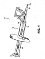
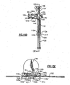
- the invention comprises a preloaded injector device for injecting an IOL into an eye.
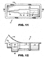
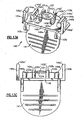
- preloaded means that the injector body 12 is packaged together with an IOL wherein the IOL 30 is held by a retainer 40 in a storage position on the injector body (see also Figures. 11 and 12 ).
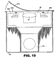
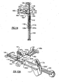
- the injector device is "partially preloaded” meaning that the IOL 30 and retainer 40 are coupled and packaged together but not yet coupled to the injector body 12 (see also Figure 10 ).
- the doctor or nurse attaches the retainer and IOL to the injector body at the time of surgery.
- the injector body 12 includes a longitudinal lumen 14 extending from the proximal end 16 to distal end 18 thereof.
- the lumen may assume any desired cross-sectional shape although circular or oval shapes are preferred.
- the lumen 14 tapers inwardly toward distal tip 18 so that the IOL 30 is gradually compressed to a very small cross-section as it exits tip 18a.
- Tip 18a may include one or more longitudinally extending slits 18a' to permit a gradual expansion of the IOL 30 as it exits the tip 18a within the eye. This prevents uncontrolled expansion of the IOL in the eye which could potentially damage the delicate surrounding tissues of the eye.
- Proximal end 16 may include a finger hold flange 17 preferably configured with a straight edge 17a as shown for resting device 10 on a flat surface.
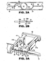
- a plunger 20 having distal and proximal lengths 20a, 20b, respectively, and a distal plunger tip 22 (see Fig. 2 ) and proximal thumb press 24 telescopes within lumen 14 for engaging and pushing the IOL 30 through lumen 14 and out of distal tip 18a.
- the IOL delivery sequence will be explained in more detail below. It is understood that the overall configuration of the injector body 12 may vary from that shown and described herein. It is furthermore understood that the components of the injector device may be made of any suitable material (e.g., polypropylene) and may be wholly or partly opaque, transparent or translucent to better visualize the IOL within the injector device and the IOL delivery sequence.
- Injector body 12 further includes an opening 26 which opens into lumen 14. Opening 26 is configured to accept an IOL 30 therein for delivery of the IOL out distal tip 18a. Discussion will now be turned to the IOL Preloaded Position followed by discussion of the IOL Load and Delivery Sequence.
- device 10 includes an IOL retainer 40 used for releasably holding an IOL 30 in the preloaded position relative to injector body 12.
- the IOL retainer 40 with IOL 30 releasably held thereby, is removably attached to the injector body 14 at opening 26.
- IOL retainer 40 includes one or more, but preferably two optic support elements 42a and 42b each having a lip 42a', 42b' or other feature for releasably supporting the IOL optic 31 at the periphery 31a thereof.
- one or more, but preferably two haptic support elements 44a and 44b are provided on retainer 40, each of which include a finger 44a', 44b' or other feature for releasably supporting one or more, but preferably two haptics 33a and 33b which attach to and extend from the optic 31.
- the IOL configuration shown and described herein is for discussion purposes only, and that the present invention is not to be limited thereby.
- the invention may be easily adapted to IOLs of any configuration and type (e.g., IOLs with plate, open or closed loop haptics, anterior chamber IOLs, posterior chamber IOLs, accommodating IOLs (including single and double lens types), etc.).
- the overall configuration of the IOL retainer 40 may thus likewise vary so as to be cooperatively configured with and releasably hold the particular IOL configuration being used with the device.
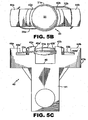
- the retainer 40 holds at least the IOL optic 31 in the unstressed state. It is furthermore preferable that retainer 40 hold the IOL haptics at the correct vault angle (i.e., the angle from which they normally extend from the IOL optic periphery). It is even furthermore preferable that the haptic support elements maintain loop haptics at the correct angle of curvature. In Figs. 5A-C , it is seen that the haptic support elements constrain the haptics along the outer curved edges thereof. This ensures that the haptic curvature, which is designed and set at manufacture of the haptics, does not increase or bend out of specification during storage of the IOL and retainer.
- the IOL 30 is releasably secured to the IOL retainer 40. This may be done by engaging the IOL optic 31 with the IOL supporting elements 42a, 42b, and/or engaging the haptics 33a, 33b with the haptic supporting elements 44a, 44b, respectively.
- haptic 33a will be referred to as the leading haptic since it becomes located distally in the injector body while haptic 33b will be referred to as the trailing haptic since it becomes located proximally in the injector body (see Fig. 2 ).
- Releasably attaching the IOL 30 to the IOL retainer 40 may be done by a worker using a pair of tweezers, for example, although other methods may be used as desired, including automated or semi-automated means.
- the retainer 40 and IOL 30 are coupled to the injector body 12 at manufacturing and sealed and sterilized in the same package for delivery to the surgeon.
- a plastic package 11 thermoformed to include a cavity 11a in the general shape of the injector device 10 is provided for packaging device 10 together with retainer 40 and IOL 30 coupled thereto.
- a flexible cover sheet 11b is sealed about the perimeter of cavity 11a to seal the package. At the time of surgery, the cover 11b is peeled back to access device 10.
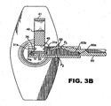
- IOL retainer 40 is removably attached to the injector body at opening 26. This may be done via suitable mechanical holding features which will removably connect the retainer 40 to the injector body 12, examples including friction fit, snap fit, interference fit, cooperative tabs and catches, detents, etc. As seen in Figures 1 and 3A , retainer 40 is held in place at opening 26 via a friction fit between the surfaces defining opening 26 and the opposite outer wall surfaces 41a and 41b of retainer 40. It will be seen that when retainer 40 and IOL 30 are coupled together and attached to injector body 12, IOL optic 31 is unstressed and furthermore does not touch any part of the injector body 12. This ensures the delicate IOL optic 31 will not be damaged during storage.
- a stripper finger 50 is located between the IOL optic 31 and the center wall surface 46 of retainer 40 as seen best in Figs. 1 , 3A and 3C .
- the primary function of the stripper finger 50 is to prevent the IOL 30 from lifting with the retainer 40 when the retainer is detached from the injector body (this operation will be described below).
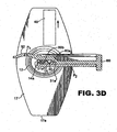
- the stripper finger 50 is attached to the compressor drawer 60 which is movable with respect to injector body 12 between a fully open position as seen in Figure 3B , a mid-way position seen in Figures 1 , 3A , 3C and 3E , and the fully closed position seen in Figures 3D , 4 , 6 and 7 .
- the stripper finger 50 is located between the IOL optic 31 and center wall surface 46 when the compressor 60 is in the mid-way position, which is also the preloaded position of the injector device as described herein.
- the stripper finger 50 moves therewith and comes to rest in a position laterally adjacent the injector body 12 as seen in Figures 3D , 4 , 6 and 7 .
- the stripper finger 50 may be formed separate from the compressor drawer 60 if desired.
- the stripper finger 50 is formed with a clip 50a which may be mounted to injector body 12 opposite to and separately of compressor drawer 60.
- the stripper finger 50 is removed from the injector body 12 after removal of retainer 40 and prior to closing the compressor drawer 60.
- Other embodiments will be apparent to those skilled in the art for stripping the IOL 30 from the retainer 40 as the retainer is removed from the injector body 12 and are thus within the scope of this invention.
- the plunger 20 includes distal and proximal plunger shaft lengths 20a, 20b, respectively, having a plunger tip 22 at the distal end thereof and a thumb press 24 at the proximal end thereof for manually operating the injector device.
- the plunger tip 22 is configured for engaging the IOL optic 31 at the periphery 31 a thereof as the plunger 20 is advanced toward the distal tip 18a of the injector body 12. It is very important that the plunger tip 22 not damage the IOL optic 31.
- the plunger tip 22 is thus designed to prevent damage to the IOL optic 31.
- the tip is bifurcated into first and second tip portions 22a and 22b, whereby the IOL optic periphery 31 a becomes engaged between tip portions 22a, 22b as seen in Figure 2B .
- the plunger shaft is rotationally fixed within lumen 14 to prevent unexpected rotation of the shaft (and thus the tip 22) with the lumen 14.
- the plunger shaft may be rotationally fixed by forming the proximal shaft length 20b and lumen 14 non-circular in cross-section.
- the proximal length 20b of the plunger shaft is provided with one or more elongated fingers 23a, 23b forming springs which are biased radially outwardly against the interior wall of lumen 14 (see Figs. 1 and 6 ).
- the purpose of spring fingers 23a, 23b is to provide proper centering of the plunger shaft and tip, as well as tactile resistance between the plunger 20 and the lumen 14 as the plunger 20 is advanced therethrough. In the storage position, the plunger 20 is retracted to the position shown in Figure 1 .
- the free ends 23a' and 23b' are located within respective openings 21a, 21b (opening 21b not shown) formed in the injector body 12 adjacent the proximal end 16 thereof.
- the bias of the spring fingers 23a, 23b against the interior wall of the lumen 14 provides the surgeon with continuous tactile feedback allowing the surgeon to advance the plunger (and thus the IOL) through the lumen 14 in a very concise and controlled manner.
- the end portion of the trailing haptic locates rearwardly of the plunger tip upon removal of retainer 40 and release of IOL 30 therefrom.
- a recessed area 25 is provided rearwardly of tip 22 on plunger shaft length 20a ( Fig. 2A ). With the plunger 20 in the ready position seen in Figure 1 , the recessed area 25 of the plunger is generally aligned with the trailing haptic 33b of the IOL 30 held by retainer 40.
- the trailing haptic 33b upon detaching retainer 40 from injector body 20, the trailing haptic 33b will release from the haptic support element 44b and fall into recessed area 25 of the plunger 20.
- the trailing haptic 33b will reside in recessed area 25 and not become entangled or otherwise interfere with the proper engagement of the plunger tip and IOL optic ( Fig. 2B ).
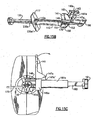
- a haptic puller 80 is provided which is the subject of commonly assigned U.S. Patent No. 6,491,697 .
- Haptic puller 80 has a shaft 82, tip 84 and finger pull 86.
- the tip 84 is inserted into the injector tip with the finger pull located outwardly adjacent thereto (see Fig. 4 ).
- the tip 84 is configured with a lip to engage the leading haptic 33a (see Fig. 2A ).
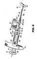
- the haptic puller 80 is grasped at finger pull 86 and pulled away from the injector body 12 in the direction of the arrow in figure 6 , thereby engaging and straightening the leading haptic 33a within tip 18, whereupon the haptic puller 80 may be discarded.
- the haptic puller tip 84 is positioned in injector tip 18 in alignment with the leading haptic 33a as it is held by the haptic supporting element 44a of IOL retainer 40.
- the leading haptic 33a releases from the haptic supporting element 44a and falls into place on the haptic puller tip 84 as shown in Figure 2A .
- the surgeon selects the injector device with the appropriate IOL preloaded therein as described above.
- the outer packaging is removed in a sterile field of the surgical suite.
- the nurse or surgeon grasps and removes IOL retainer 40 from injector body 12. This is accomplished by manually grasping finger grip 41 and pulling the retainer 40 away from the injector body 12 as shown by directional arrow 1 in Figure 4 .
- the stripper finger 50 acts to prevent the IOL 30 from lifting together with retainer 40.
- the IOL optic 31 will release from the IOL optic support element 42a, 42b and the leading and trailing haptics 33a, 33b will release from their respective haptic support elements 44a, 44b.
- the retainer 40 may be discarded or recycled.
- the IOL 30 thus fully released from retainer 40, the IOL optic 31 comes to rest in the loading bay area 27 of the injector lumen 14 with the leading haptic 33a engaging the haptic puller tip 84 and the trailing haptic 33b locating in the recessed area 25 adjacent the plunger tip 22 as described above.
- IOL 30 upon release of the IOL 30 from the retainer 40, IOL 30 will drop slightly in lumen 14.
- lumen 14 together with lumen groove 14a, drawer groove 60a, and drawer top wall 60b compresses and encases IOL optic 31 within lumen 14.
- the locating of the optic periphery 31a inside opposite grooves 14a and 60a ensures a planar delivery of the IOL 30 through lumen 14 and out tip 18. This manner of IOL planar delivery is described in more detail in commonly assigned U.S. Patent No. 6,491,697 referred to above.
- one or more viscoelastic access ports are provided on the injector device to facilitate application of the viscoelastic in the area of the IOL.
- One or more access ports P 1 may thus be provided in the form of a through-hole in stripper finger 50. The access port P 1 is accessible via an injection nozzle inserted into visco port P 1 .
- one or more access ports P 2 may be provided at any desired location through the wall of tip 18 (see Figs. 3B-D ).
- visco ports P 1 and P 2 visco may be applied in loading bay 27 at the openings P 3 and P 4 defined between the optic and haptic support elements of retainer 40 (see Fig. 3A ). Once the viscoelastic has been applied as desired, retainer 40 is removed and the compressor drawer 60 is moved to the fully closed position whereupon the IOL optic 31 is compressed and ready for delivery through a small incision formed in an eye. The fully closed position of drawer 60 and compressed position of the IOL 30 is seen in Figure 3D as described above.
- Drawer 60 is slidably received between cooperatively formed drawer slides 61a, 61b extending laterally from injector body 12 adjacent opening 26.
- Detents or other features may be provided on the facing surfaces of drawer slides 61a, 61b and drawer 60 to assist in maintaining drawer 60 in the fully open and mid-way positions, respectively.
- Such drawer holding features are especially useful in preventing unintentional sliding and /or complete closing of drawer 60 prior to the time needed (e.g., during storage or opening of device 10 from its associated packaging).
- the haptic puller 80 is pulled away from the injector body 12 ( Fig. 6 ) and the leading haptic 33a is straightened within injector tip 18.
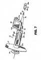
- the plunger 20 may be advanced slightly prior to removing the haptic puller 80. The surgeon inserts the injector tip 18a into the incision cut into the eye and begins advancing the plunger 20. As the plunger 20 is advanced, the plunger tip 22 engages the optic periphery 31 a and pushes IOL 30 forwardly with the trailing haptic 33b remaining located in recess 25 of plunger 20. Upon continued advancement of the plunger 20, the IOL 30 is pushed through the injector tip 18a and is finally expressed therefrom and into the eye ( Fig. 7 ).
- a helical spring 27 may be provided about plunger shaft distal length 20a to provide increasing bias in the reverse direction as the plunger reaches the fully advanced position. This occurs as spring 27 is compressed between the leading edge 20b' of proximal shaft length 20b and the radial extension 12a of injector body 12 (see Figs. 1 and 6 ). This assists the surgeon in maintaining precise control over plunger (and hence IOL) advancement and allows automatic retraction of the plunger upon relieving the pushing pressure being exerted against the plunger thumb press 24. This is useful for easily executing a second stroke of the plunger in order to engage and manipulate the trailing haptic into place in the eye. This feature, together with the bifurcated plunger tip 22, allows a more precise control and manipulation of the IOL with the plunger tip in-situ than would be possible with an injector device not having these features.
- the injector device is "partially preloaded", meaning that the IOL 30 and retainer 40 are coupled together as shown in Figures 5A-C and sealed in a package 51 as shown in Fig. 10 which is separate from another package in which the injector body 12 is supplied.
- Package 51 may be thermoformed to include a cavity 51a in the general shape of retainer 40 and IOL 30 as coupled together.
- a flexible cover sheet 51b is sealed about the perimeter of cavity 51a to seal the retainer 40 and IOL 30 in package 51.
- This embodiment allows the doctor to choose a package having a retainer and specific IOL model therein. This is then combined with the separately packaged injector body 12 which is common to all IOL models.
- the doctor or nurse removes cover 51b to retrieve retainer 40 and IOL 30 therefrom.
- the injector body 12 is removed from its respective packaging and the retainer 40 having an IOL 30 already coupled thereto is attached to the injector body 12 at the time of surgery. It will be appreciated that direct handling and manipulation of the IOL 30 itself is not required in either the preloaded or partially preloaded embodiments of the invention.
- the injector body 12 is supplied with the compressor drawer 60 in the fully open position seen in Figure 3B such that the stripper finger 50 is located laterally adjacent the opening 26 (or the stripper finger is not yet attached to the injector body 12 where the stripper finger is a separate component).
- the nurse or doctor then opens the package housing the inserter body and proceeds to couple the retainer and IOL to the injector body through opening 26.
- the stripper finger 50 is inserted between the retainer wall surface 46 and IOL optic 31. This may be done by advancing the compressor drawer 60 to the mid-way position seen in Figures 1 , 3A and 3C . In the embodiment shown in Figure 3E , this is accomplished by attaching the stripper finger 50 and clip 50a combination to the injector body 12 opposite drawer 60.
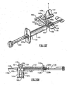
- FIGS. 13A-16A illustrate another preferred embodiment of the invention.
- the reference numerals used in the embodiments of previous Figures 1-12 will be used for similar parts found in Figs. 13A-16B increased by 100. Unless stated otherwise, the description of other embodiments applies to this embodiment as well.
- a retainer 140 for releasably holding an IOL is seen to include one or more, but preferably two optic support elements 142a and 142b each having a groove 142a', 142b' or other feature for releasably supporting the IOL optic 131 at the periphery 131a thereof.
- the grooves 142a', 142b' are spaced above the support surface 146 such that the optic 131 is likewise spaced above support surface 146.
- the distance between the support surface and optic is selected to enable the stripper finger 150 of the compressor drawer 160 to extend therebetween as explained more fully below.
- the upper surfaces 142a" and 142b" are slanted downwardly to provide a "lead-in" which facilitates positioning of the optic periphery 131a into gooves 142a', 142b'.
- one or more, but preferably two haptic support elements 144a and 144b are provided on retainer 140, each of which include a groove 144a', 144b'or other feature for releasably supporting one or more, but preferably two haptics 133a and 133b which attach to and extend from the optic 131.
- the retainer 140 holds at least the IOL optic 131 in the unstressed state. It is furthermore preferable that retainer 140 hold the IOL haptics at the correct vault angle (i.e., the angle from which they normally extend from the IOL optic periphery).
- the haptic support elements maintain loop haptics at the correct lens diameter d 1 (see Fig. 13G ).
- Figs. 13A-D it is seen that the haptic support elements 144a, 144b constrain the haptics 144a', 144b' along the outer curved edges thereof, respectively. This ensures that the lens diameter d 1 , which is designed and set at manufacture, does not increase or bend out of specification during storage of the IOL and retainer.
- a slot 143 is provided in at least one optic support element 142b wherein respective haptic 133b extends adjacent optic 131. Slot 143 acts to inhibit lateral translation or counter-clockwise rotation of IOL 130 (as viewed in Figs 13A and B ) while coupled to retainer 140, particularly during shipping and storage thereof.
- haptic 133b will encounter and abut the side wall 143' defining the slot 143 and translation and rotation are thus inhibited.
- translation or rotation of the IOL in the clock-wise direction is inhibited by the inside walls 142a", 142b" which the haptics will encounter and abut should they begin to translate or move in the clockwise direction.
- the retainer and IOL combination is ready to be attached to the injector device 112. As described above in relation to previous embodiments, this may be done at the time of manufacture, at the time of use by the surgeon or nurse, or any time therebetween.
- Retainer 140 may further include first and second attachment legs 145a, 145b extending from opposite edges of surface 146. Legs 145a and 145b are spaced apart a distance enabling retainer 140 to be removably attached to device 112 as seen in Figs. 15A-15D by straddling drawer slides 161a, 161b which extend laterally from injector body 112 adjacent opening 126. Legs 145a, 145b may be provided with catches 145a', 145b' at the ends thereof to provide a snap-fit engagement between retainer 140 and drawer slides 161a, 161b, respectively.
- first and second flanges 165a, 165b are provided at the junctures of drawer slides 161a, 161b and device body 112, respectively, and act to precisely locate legs 145a, 145b thereagainst and thus precisely locate retainer 140 on device body 112.
- Retainer 140 may further include first and second flanges 147a, 147b, which rest on drawer slides 161a, 161b when the retainer 140 is properly positioned on device body 112 as described above.
- Flanges 147a, 147b help stabilize retainer 140 on device body 112 and also aid the user in pivoting the retainer off the device about the flange corners 147a', 147b' which act as the pivot points (see also Fig. 15C ).
- a protective cover 200 which may be removably coupled to retainer 140 ( Figs. 13E-F ).
- Cover 200 includes a finger grasp flange 204 extending from enclosure 202 having four side walls 206a, 206b, 206c and 206d and a top wall 206e all defining a central opening 208.
- Opposite side walls 206b and 206d each include a flange 206b', 206d' adjacent opening 208.
- Flanges 206b', 206d' each include a notch 206b", 206d" wherein the first and second attachment legs 145a, 145b of retainer 140 may freely slide, respectively.
- the two parts are aligned as seen in Fig. 13D and moved together until retainer surface 146 rests upon the flanges 206b', 206d' and catches 145a', 145b' engage top cover top wall 202e as seen in Fig. 13E .
- the IOL optic 131 remains coupled to retainer 140.
- the interior of top wall 206e' may be provided with features to assist in providing clearance and/or support to the IOL.
- a circular recess 210 may be provided which aligns with the position of IOL optic 131 to ensure there is enough clearance to prevent the IOL optic 131 from touching interior wall 206e'.
- One or more protrusions such as at 212 and 214 may also be provided to act as auxiliary supports for the optic peripheral edge 131a.
- One or more protrusions 218, 220 may be provided to act as auxiliary supports for haptics 133a and 133b, respectively.
- the compressor drawer 160 Prior to attaching retainer 140 and IOL 130 combination to device 112, the compressor drawer 160 is set to the open position as seen in Figs. 14 and 15A .
- the compressor drawer 160 includes opposite side rails 161a, 161b with a spring arm 161c extending therebwetween, a finger press 160c, an optic stripper finger 150 and first and second haptic stripper fingers 151 and 153 extending generally parallel to and spaced on either side of optic stripper finger 150.
- the leading edges of the optic and haptic stripper fingers 150, 151, 153 lie laterally spaced from opening 126 as seen best in Fig. 14 .
- the leading edge 163a of arm 163 has a groove which engages the leading edge 161d of shelf 161c to prevent unintended further advancement of drawer 160 with respect to device 112.
- This feature allows the open position of the drawer 160 to be correctly set at manufacturing and prevent premature advancement of the drawer during shipping and handling.
- the retainer and IOL combination may be mounted thereto over opening 126 by grasping retainer 140 by finger grasp 141 and straddling legs 145a, 145b about drawer slides 161a, 161b as described above.
- drawer finger press 160c When it is time to use the device at surgery, the surgeon or nurse presses upon drawer finger press 160c while also pressing upward on arm 163 (e.g., with the thumb) to disengage the arm leading edge 163a from the shelf leading edge 161d. Once this is done, the drawer 160 is advanced further toward opening 126 of device 112 with arm 163 passing over shelf 161c. Advancement of the drawer is continued until stripper fingers 150, 151 and 153 have extended between the IOL 130 and retainer surface 146 as seen best in Figs. 15B , 15D and 15E . This position will be realized by the user when vertically extending flange 160d of drawer 160 (see Figs. 15D and 16B ) abuts edge 146a of retainer surface 146 (see Fig. 15D ).
- retainer 140 may be decoupled from device 112 by grasping finger pull 141 and pulling away from the device 112 as seen in Fig. 15F . It is noted that the retainer 140 may be pulled straight (arrow in Fig. 15F ) or in a pivoting movement (arrow in Fig. 15C ) with respect to the device body 112. Prior to and/or after decoupling retainer 140, the surgeon may apply viscoelastic to the IOL 130 through opening 126 and/or opening 150a.
- central stripper finger 150 acts to strip the IOL optic 131 from retainer 140 while stripper fingers 151 and 153 act to strip respective haptics 133a and 133b therefrom. Besides acting to strip the IOL from the retainer, the stripper fingers also assist in maintaining the IOL at least partly submerged in the viscoelastic puddle as applied by the surgeon. Without this assistance by the stripper fingers, the IOL may "float" on top of the viscoelastic which can be detrimental to a successful IOL delivery. It is also noted that the opening 150a in optic stripper finger 150 assists in stabilizing the IOL optic 31 as it is being stripped away from retainer 140.
- the two haptics may release from their respective haaptic support elements at different times causing the optic to "tilt" in the direction of the haptic as it releases from its associated support element.
- Opening 150a thus assists in keeping the optic from tilting by providing a 360° surface against which the 360° peripheral edge 131a may press against during the stripping process.
- Opening 150a' may further be provided with an angled lead-in edge 150a' ( Fig. 16C ) to enhance this stabilizing effect.
- the IOL 130 is positioned in opening 126 in the manner described above (see Fig. 2A ) and is ready for folding and delivery into an eye.
- the user thus proceeds by continuing to advance drawer 160 to the fully closed position by pressing inwardly on drawer finger press 160c.
- a lateral opening 155 is provided in body 112 opposite drawer 60 (see Figs. 14 and 15F ). Opening 155 is provided to allow the free end of the trailing haptic 133b to pass therethrough should the closing of drawer 160 begin to pinch this haptic.
- a finger grasp 170 may be provided on device 112 opposite drawer 160 to help the user hold the device while closing the drawer.
- the fully closed position of drawer 160 is seen in Fig. 16A . In this position, stripper fingers 150, 151 and 153 are now located laterally of device 112 over flange 170. The IOL 130 is compressed and ready for delivery.
- haptic puller 180 is pulled away from the injector body 112 (see Fig. 6 ) and the leading haptic 133a is straightened within injector tip 118.
- haptic puller 180 includes a finger pull 186 and a shaft 182 and tip 184.
- the tip 184 is inserted into the injector tip with the finger pull located outwardly adjacent thereto (see Fig. 14 ).
- the tip 184 is configured with a lip to engage the leading haptic 133a (see Fig. 14 and 15E ).
- the haptic puller 180 is grasped at finger pull 186 and pulled away from the injector body 112, thereby engaging and straightening the leading haptic 133a within tip 118, whereupon the haptic puller 180 may be discarded.
- the haptic puller tip 184 is positioned in injector tip 118 in alignment with the leading haptic 133a as it is held by the haptic supporting element 144a of IOL retainer 140.
- the leading haptic 133a releases from the haptic supporting element 144a and falls into place on the haptic puller tip 184.
- a positioning nub 183 is formed on finger pull 186 and abuts the tip 118 when the haptic puller shaft 182 is fully inserted into the inserter tip 118. Nub 183 substantially inhibits lateral movement of the shaft 182 within tip 118 and thereby ensures proper and stable alignment of the haptic puller tip 184 with the retainer 140 and leading haptic 133a held thereby.
- the plunger 120 may be advanced slightly prior to removing the haptic puller 180. The surgeon inserts the injector tip 118a into the incision cut into the eye and begins advancing the plunger 120. As the plunger 120 is advanced, the plunger tip 122 engages the optic periphery 131a and pushes IOL 130 forwardly with the trailing haptic 133b locating in recess 125a of plunger 120. It is noted that plunger 120 may also include a recess 125b opposite recess 125a (see Fig. 18 ).
- Second recess 125b is provided so that if trailing haptic 133b fails to align with and become located in the first recess 125a, the trailing haptic will instead become located in the second recess 125b and thus have clearance to travel through and out the device lumen.
- the plunger 120 Upon continued advancement of the plunger 120, the IOL 130 is pushed through the injector tip 118a and is finally expressed therefrom and into the eye.
- a pair of spring springs 220a, 220b having respective tips 220a', 220b' may be provided on the plunger shaft.
- Injector body 112 may likewise be provided with a pair of through holes 112a, 112b wherethrough the tips may reside to set the initial (shipping) position of the plunger 120.
- Pressing the plunger causes the tips to retract out of holes 112a, 112b and thereafter provide bias against the interior of body 112. This assists the surgeon in maintaining precise control over plunger (and hence IOL) advancement.
- a spring (not shown) may also be provided about plunger shaft 120 to allow automatic retraction of the plunger upon relieving the pushing pressure being exerted against the plunger thumb press 24 as described above.
Landscapes
- Health & Medical Sciences (AREA)
- Ophthalmology & Optometry (AREA)
- Cardiology (AREA)
- Oral & Maxillofacial Surgery (AREA)
- Transplantation (AREA)
- Engineering & Computer Science (AREA)
- Biomedical Technology (AREA)
- Heart & Thoracic Surgery (AREA)
- Vascular Medicine (AREA)
- Life Sciences & Earth Sciences (AREA)
- Animal Behavior & Ethology (AREA)
- General Health & Medical Sciences (AREA)
- Public Health (AREA)
- Veterinary Medicine (AREA)
- Prostheses (AREA)
- Infusion, Injection, And Reservoir Apparatuses (AREA)
- Percussion Or Vibration Massage (AREA)
Claims (19)
- IOL-Injektorvorrichtung (10), die zwischen einem vorbeladenen IOL-Zustand und einem anschließenden beladenen IOL-Zustand umschaltbar ist, wobei im vorbeladenen IOL-Zustand die Injektorvorrichtung aufweist:a) einen Injektorkörper (12) mit einem proximalen (16) und einem distalen (18) entgegengesetzten Ende und einem sich dazwischen längs erstreckenden Lumen (14);b) einer Halterung (40), die an einer im Injektorkörper gebildeten Öffnung (26) entfernbar angebracht ist, wobei die Halterung geeignet ist, eine IOL (30) in einer vorbeladenen Position im Hinblick auf den Injektorkörper lösbar zu halten; undc) einen Kolben (20) zum Vorschieben der IOL durch das Lumen und aus dem distalen Ende des Injektorkörpers;
dadurch gekennzeichnet, daß die Vorrichtung zusätzlich aufweist:d) einen Stripperfinger (50), der zwischen der IOL und der Halterung (40) liegt; unddie Injektorvorrichtung so konfiguriert ist, daß sie auf den beladenen IOL-Zustand durch Ablösen der Halterung (40) vom Injektorkörper (12) mit dem Stripperfinger (50) umschaltet, der so wirkt, daß er die IOL (30) am Lösen mit der Halterung (40) hindert und dadurch bewirkt, daß die IOL (30) zum anschließenden Eingriff durch den Kolben (20) im Lumen (14) zu liegen kommt. - Injektorvorrichtung nach Anspruch 1, wobei die Injektorvorrichtung mit der Halterung (40) und der IOL (30) in derselben Verpackung (11) abgedichtet ist, während sie sich im vorbeladenen IOL-Zustand befindet.
- Injektor nach Anspruch 1 und ferner mit einem Kompressor (60) zum Komprimieren der IOL (30) im Lumen (14) vor Eingriff durch den Kolben, wobei der Kompressor mit dem Injektorkörper verbunden und zwischen einer offenen und einer geschlossenen Position im Hinblick darauf beweglich ist und die geschlossene Position dazu führt, daß die IOL innerhalb des Lumens komprimiert wird.
- Injektorvorrichtung nach Anspruch 3, wobei der Stripperfinger am Kompressor angebracht und damit beweglich ist.
- Injektorvorrichtung nach Anspruch 1, wobei der Stripperfinger an einem Clip (50a) angebracht ist, der geeignet ist, am Injektorkörper entfernbar angebracht zu werden.
- Injektorvorrichtung nach Anspruch 1, wobei der Stripperfinger ein Durchgangsloch mit einem viskoelastischen Zugangsport (P1) aufweist.
- Injektorvorrichtung nach Anspruch 1, wobei der Injektorkörper ein Durchgangsloch mit einem viskoelastischen Port (P2) aufweist.
- Injektorvorrichtung nach Anspruch 1 und ferner mit einem Haptik-Zieher (80) mit einer Haptik-Zieherspitze (84), die im vorbeladenen Zustand der IOL-Injektionsvorrichtung im Lumen positioniert ist, wobei die Haptik-Zieherspitze so konfiguriert ist, daß sie die vorlaufende Haptik (33a) der IOL (30) ergreift und anschließend die vorlaufende Haptik in der distalen Spitze (18) des Injektorkörpers beim Entfernen des Haptik-Ziehers aus dem Injektorkörper geraderichtet.
- Injektorvorrichtung nach Anspruch 1, wobei der Kolben (20) eine Kolbenspitze (22) zum Ergreifen der IOL und eine im Kolben benachbart zur Kolbenspitze gebildete Aussparung (25, 125a) aufweist, wobei die Aussparung geeignet ist, die nachlaufende Haptik (33b) der IOL hinter der Kolbenspitze anzuordnen.
- Injektorvorrichtung nach Anspruch 1, wobei der Kolben (20) eine proximale (20b) und eine distale Schaftlänge aufweist, und ferner mit einem oder mehreren Federfingerelementen (23a, 23b), die an der proximalen Schaftlänge angebracht und so betriebsfähig sind, daß sie eine Vorspannkraft auf das Innere des Injektorkörperlumens (14) ausüben, wenn der Kolben durch den Injektorkörper geschoben wird.
- Injektorvorrichtung nach Anspruch 10, wobei der Injektorkörper ein proximales (16) und ein distales Ende (18) aufweist, und ferner mit einer oder mehreren Öffnungen, die benachbart zu seinem proximalen Ende durchgehend gebildet sind, und wobei der eine oder die mehreren Federfinger jeweils ein freies Ende (23a', 23b') haben, das in einer jeweiligen Öffnung entfernbar angeordnet werden kann.
- Injektorvorrichtung nach Anspruch 1, wobei der Kolben eine proximale und eine distale Schaftlänge aufweist, wobei die proximale Schaftlänge mit dem Lumen so zusammenwirkend konfiguriert ist, daß sie den Kolben im Hinblick auf das Lumen gegen Drehung befestigt.
- Injektorvorrichtung nach Anspruch 12, wobei die proximale Schaftlänge eine Vorderkante (20b') aufweist und das Lumen (14) eine Radialverlängerung (12a) aufweist, und ferner mit einer Schraubenfeder (27), die an der distalen Kolbenschaftlänge angebracht und zwischen der Vorderkante (20b') und der Radialverlängerung (12a) zusammendrückbar ist, wenn der Kolben durch den Injektorkörper vorgeschoben wird.
- Vorrichtung nach Anspruch 9, wobei die Aussparung eine erste Aussparung (125a) ist, und ferner mit einer zweiten Aussparung (125b) in der Kolbenspitze, die entgegengesetzt zur ersten Aussparung liegt, wobei die zweite Aussparung der nachlaufenden Haptik ermöglicht, darin zu liegen zu kommen, sollte die nachlaufende Haptik nicht in der ersten Aussparung zu liegen kommen.
- Injektorvorrichtung nach Anspruch 1, wobei die Injektorvorrichtung so konfiguriert ist, daß der Stripperfinger (50) in einer festen Lage relativ zum Injektorkörper gehalten wird, während die IOL veranlaßt wird, im Lumen zu liegen zu kommen.
- Kolben zum Einschieben/Ausziehen in einem Lumen (14), das durch eine Lumenwand eines Intraokularinjektorkörpers gebildet ist, dadurch gekennzeichnet, daß der Kolben einen Kolbenschaft hat, der mindestens einen länglichen Federfinger (23a) mit einem am Kolbenschaft befestigten ersten Ende und einem sich zur Kolbenspitze erstreckenden zweiten, freien Ende (23a') aufweist, wobei das freie Ende eine Vorspannkraft auf die Lumenwand ausübt.
- Kolben nach Anspruch 16 und ferner mit einem zweiten länglichen Federfinger (23b) mit einem am Kolbenschaft befestigten ersten Ende und einem sich zur Kolbenspitze erstreckenden zweiten, freien Ende, wobei das zweite freie Federfingerende (23b') eine Vorspannkraft auf die Lumenwand auf einer zum ersten freien Federfingerende entgegengesetzten Seite des Schafts ausübt.
- Verfahren zum gemeinsamen Verpacken einer IOL (30) und eines Injektors (10) mit den Schritten:a) Bereitstellen einer IOL mit einer Optik;b) Bereitstellen einer IOL-Halterung (40), die geeignet ist, die IOL lösbar zu halten, und lösbares Anbringen der IOL an der Halterung;c) Bereitstellen eines Injektorkörpers (12) mit einem IOL-Abgabedurchgang und entfernbares Anbringen der Halterung und der IOL am Injektorkörper, wobei die IOL in Verbindung mit dem Abgabedurchgang steht;d) Bereitstellen eines Kompressors (60) zum Komprimieren der IOL im Injektorkörper;
dadurch gekennzeichnet, daß das Verfahren ferner aufweist:e) Bereitstellen eines Stripperelements (50) und Anordnen des Stripperelements zwischen der IOL und der Halterung; undf) Bereitstellen einer Verpackung (11) und Plazieren des Injektorkörpers mit der Halterung, der IOL, dem Kompressor und dem Stripperelement in einer Verpackung zur Lieferung an einen Chirurgen. - Verfahren nach Anspruch 18 und ferner mit einem Schritt des Sterilisierens der Verpackung vor Lieferung an den Chirurgen.
Applications Claiming Priority (3)
| Application Number | Priority Date | Filing Date | Title |
|---|---|---|---|
| US10/651,785 US7429263B2 (en) | 2003-08-28 | 2003-08-28 | Preloaded IOL injector |
| US10/813,862 US7422604B2 (en) | 2003-08-28 | 2004-03-31 | Preloaded IOL injector |
| EP04781647.5A EP1659991B2 (de) | 2003-08-28 | 2004-08-19 | Vorbeladener iol-injektor |
Related Parent Applications (2)
| Application Number | Title | Priority Date | Filing Date |
|---|---|---|---|
| EP04781647.5 Division | 2004-08-19 | ||
| EP04781647.5A Division EP1659991B2 (de) | 2003-08-28 | 2004-08-19 | Vorbeladener iol-injektor |
Publications (3)
| Publication Number | Publication Date |
|---|---|
| EP1674050A2 EP1674050A2 (de) | 2006-06-28 |
| EP1674050A3 EP1674050A3 (de) | 2006-07-05 |
| EP1674050B1 true EP1674050B1 (de) | 2010-09-22 |
Family
ID=34279068
Family Applications (3)
| Application Number | Title | Priority Date | Filing Date |
|---|---|---|---|
| EP04781647.5A Active EP1659991B2 (de) | 2003-08-28 | 2004-08-19 | Vorbeladener iol-injektor |
| EP06003936A Active EP1671607B1 (de) | 2003-08-28 | 2004-08-19 | Kompressionsschublade für IOL-Injektor |
| EP06003906A Active EP1674050B1 (de) | 2003-08-28 | 2004-08-19 | Vorbeladener IOL-Injektor |
Family Applications Before (2)
| Application Number | Title | Priority Date | Filing Date |
|---|---|---|---|
| EP04781647.5A Active EP1659991B2 (de) | 2003-08-28 | 2004-08-19 | Vorbeladener iol-injektor |
| EP06003936A Active EP1671607B1 (de) | 2003-08-28 | 2004-08-19 | Kompressionsschublade für IOL-Injektor |
Country Status (12)
| Country | Link |
|---|---|
| US (1) | US7422604B2 (de) |
| EP (3) | EP1659991B2 (de) |
| JP (1) | JP4460579B2 (de) |
| KR (1) | KR101119307B1 (de) |
| CN (1) | CN1845712B (de) |
| AU (1) | AU2004270163B2 (de) |
| CA (2) | CA2533867C (de) |
| DE (3) | DE602004021188D1 (de) |
| ES (2) | ES2318596T3 (de) |
| HK (3) | HK1090535A1 (de) |
| TW (1) | TWI342768B (de) |
| WO (1) | WO2005023154A2 (de) |
Families Citing this family (116)
| Publication number | Priority date | Publication date | Assignee | Title |
|---|---|---|---|---|
| FR2833154B1 (fr) | 2001-12-12 | 2004-11-19 | Ioltechnologie Production | Cassette et injecteur de lentille intraoculaire souple et procede d'injection de telles lentilles |
| US10835373B2 (en) | 2002-12-12 | 2020-11-17 | Alcon Inc. | Accommodating intraocular lenses and methods of use |
| US7429263B2 (en) * | 2003-08-28 | 2008-09-30 | Bausch & Lomb Incorporated | Preloaded IOL injector |
| AU2003274416A1 (en) * | 2003-09-26 | 2005-04-14 | Bausch And Lomb Incorporated | Preloaded iol injector and method of packaging |
| JP4520256B2 (ja) * | 2004-09-06 | 2010-08-04 | 株式会社ニデック | 眼内レンズ挿入器具 |
| JP4520255B2 (ja) * | 2004-09-06 | 2010-08-04 | 株式会社ニデック | 眼内レンズ挿入器具 |
| EP1832247B1 (de) | 2004-12-27 | 2015-06-24 | Hoya Corporation | Vorrichtung zur implantation einer intraokularlinse |
| JP4766442B2 (ja) * | 2004-12-28 | 2011-09-07 | Hoya株式会社 | 眼内レンズ挿入用器具 |
| US20060142781A1 (en) * | 2004-12-29 | 2006-06-29 | Joel Pynson | Preloaded IOL injector and method |
| WO2006070219A1 (en) * | 2004-12-29 | 2006-07-06 | BAUSCH & LOMB INCORPORATED Société américaine régie selon les lois de New York | Preloaded iol injector |
| JP5221949B2 (ja) | 2005-01-26 | 2013-06-26 | Hoya株式会社 | 眼内レンズ挿入用器具 |
| JP4836046B2 (ja) | 2005-02-24 | 2011-12-14 | Hoya株式会社 | 眼内レンズ挿入器具 |
| US20070010879A1 (en) * | 2005-07-07 | 2007-01-11 | Gregg Feinerman | Injector system for a lens |
| WO2007037223A1 (ja) | 2005-09-28 | 2007-04-05 | Hoya Corporation | 眼内レンズ挿入用器具 |
| JP4520390B2 (ja) * | 2005-09-29 | 2010-08-04 | 株式会社ニデック | 眼内レンズ挿入システム |
| JP4767671B2 (ja) * | 2005-12-02 | 2011-09-07 | 株式会社ニデック | 眼内レンズ挿入システム |
| JP4877643B2 (ja) | 2005-12-08 | 2012-02-15 | Hoya株式会社 | 眼内レンズ挿入用器具 |
| JPWO2007080868A1 (ja) * | 2006-01-10 | 2009-06-11 | Hoya株式会社 | 眼内レンズ挿入器具 |
| JP4699216B2 (ja) * | 2006-01-11 | 2011-06-08 | 株式会社ニデック | 眼内レンズ挿入システム |
| JPWO2007080869A1 (ja) * | 2006-01-13 | 2009-06-11 | Hoya株式会社 | 眼内レンズ挿入用器具 |
| US8460375B2 (en) * | 2006-08-14 | 2013-06-11 | Novartis Ag | Lens delivery system |
| KR100763505B1 (ko) * | 2006-08-17 | 2007-10-05 | 강다원 | 가축 인공수정기 커버 |
| JP4908977B2 (ja) * | 2006-09-05 | 2012-04-04 | 興和株式会社 | 眼内レンズの挿入器具 |
| US9149619B2 (en) * | 2006-09-22 | 2015-10-06 | Lenstec Barbados Inc. | System and method for storing, shipping and injecting ocular devices |
| US9681947B2 (en) * | 2006-10-23 | 2017-06-20 | Novartis Ag | Intraocular lens delivery system with temperature control |
| US20080147082A1 (en) * | 2006-12-13 | 2008-06-19 | Joel Pynson | Injector apparatus for use with intraocular lenses and methods of use |
| US7879090B2 (en) * | 2006-12-13 | 2011-02-01 | Bausch & Lomb Incorporated | Intraocular lens injector apparatus and methods of use |
| US20080154361A1 (en) * | 2006-12-22 | 2008-06-26 | Joel Pynson | Intraocular lens injector subassembly |
| US9522061B2 (en) * | 2007-02-15 | 2016-12-20 | Novartis Ag | Lens delivery system |
| US20080255577A1 (en) * | 2007-04-11 | 2008-10-16 | Downer David A | Lens Delivery System Cartridge and Method of Manufacture |
| EP2161004B1 (de) | 2007-05-30 | 2017-12-27 | Hoya Corporation | Instrument zum einsetzen einer intraokularlinse |
| EP2161005B1 (de) | 2007-05-30 | 2016-12-28 | Hoya Corporation | Instrument zum einsetzen einer intraokularlinse |
| US20090005788A1 (en) * | 2007-06-26 | 2009-01-01 | Rathert Brian D | Intraocular Lens Injector |
| JP5086713B2 (ja) | 2007-07-11 | 2012-11-28 | Hoya株式会社 | 眼内レンズ挿入器具 |
| US8968396B2 (en) | 2007-07-23 | 2015-03-03 | Powervision, Inc. | Intraocular lens delivery systems and methods of use |
| EP2647353B1 (de) | 2007-07-23 | 2014-12-31 | PowerVision, Inc. | Linseneinführsystem |
| JP5330401B2 (ja) | 2007-11-08 | 2013-10-30 | アリメラ・サイエンシーズ,インコーポレーテッド | 眼のための埋め込み装置、及びその装置を備えるキット |
| US8894664B2 (en) | 2008-02-07 | 2014-11-25 | Novartis Ag | Lens delivery system cartridge |
| JP5254669B2 (ja) | 2008-06-05 | 2013-08-07 | Hoya株式会社 | 眼内レンズ挿入器具及びカートリッジ |
| JP5470753B2 (ja) | 2008-06-17 | 2014-04-16 | Hoya株式会社 | 眼内レンズ挿入器具 |
| US8273122B2 (en) | 2008-06-23 | 2012-09-25 | Abbott Medical Optics Inc. | Pre-loaded IOL insertion system |
| JP5323420B2 (ja) * | 2008-08-21 | 2013-10-23 | Hoya株式会社 | 眼内レンズ挿入器具 |
| JP5416379B2 (ja) | 2008-09-04 | 2014-02-12 | Hoya株式会社 | 眼内レンズ挿入器具 |
| KR100893138B1 (ko) * | 2008-09-19 | 2009-04-16 | 주식회사 알이티 | 인공수정체가 내장된 일회용 인공수정체 주입장치 |
| CH699588A1 (de) * | 2008-09-22 | 2010-03-31 | Medicel Ag | Kassette für eine intraokulare Linse und Injektorsystem dafür. |
| US20100087832A1 (en) * | 2008-10-03 | 2010-04-08 | Seyboth William J | Intraocular lens injector |
| US8801780B2 (en) | 2008-10-13 | 2014-08-12 | Alcon Research, Ltd. | Plunger tip coupling device for intraocular lens injector |
| US8308736B2 (en) | 2008-10-13 | 2012-11-13 | Alcon Research, Ltd. | Automated intraocular lens injector device |
| US8808308B2 (en) | 2008-10-13 | 2014-08-19 | Alcon Research, Ltd. | Automated intraocular lens injector device |
| JP5301942B2 (ja) * | 2008-10-17 | 2013-09-25 | 株式会社ニデック | 眼内レンズ挿入器具 |
| WO2010079780A1 (ja) | 2009-01-07 | 2010-07-15 | Hoya株式会社 | 眼内レンズ挿入器具 |
| US10299913B2 (en) | 2009-01-09 | 2019-05-28 | Powervision, Inc. | Accommodating intraocular lenses and methods of use |
| MX2011008381A (es) * | 2009-02-11 | 2011-09-06 | Alcon Res Ltd | Dispositivo inyector de lentes intraoculares automatico. |
| JP5501658B2 (ja) * | 2009-05-29 | 2014-05-28 | 株式会社ニデック | 眼内レンズ挿入器具 |
| US9492272B2 (en) | 2009-08-13 | 2016-11-15 | Acufocus, Inc. | Masked intraocular implants and lenses |
| US10004593B2 (en) | 2009-08-13 | 2018-06-26 | Acufocus, Inc. | Intraocular lens with elastic mask |
| GB2472872B (en) | 2009-08-18 | 2014-12-31 | Carl Zeiss Meditec Sas | Holding device for an intraocular lens, packaging and transport means for an intraocular lens and injector device for an intraocular lens. |
| US20110152872A1 (en) * | 2009-12-23 | 2011-06-23 | Seyboth William J | Intraocular lens injector including a shaped spring |
| JP5602437B2 (ja) * | 2010-01-09 | 2014-10-08 | 株式会社ニデック | 眼内レンズ挿入器具 |
| EP2343029B1 (de) * | 2010-01-09 | 2015-05-06 | Nidek Co., Ltd. | Einspritzinstrument für eine Intraokularlinse |
| EP2555708B1 (de) | 2010-04-08 | 2015-03-18 | Hoya Corporation | Vorrichtung zum einsetzen eines augenimplantats |
| US8308799B2 (en) | 2010-04-20 | 2012-11-13 | Alcon Research, Ltd. | Modular intraocular lens injector device |
| CN102985030A (zh) * | 2010-04-22 | 2013-03-20 | R·S·米尔拉伊 | 改善的人工晶状体注入设备 |
| JP5511530B2 (ja) | 2010-06-10 | 2014-06-04 | Hoya株式会社 | 眼内レンズ挿入装置 |
| WO2012006616A2 (en) | 2010-07-09 | 2012-01-12 | Powervision, Inc. | Intraocular lens delivery devices and methods of use |
| US8579969B2 (en) | 2010-07-25 | 2013-11-12 | Alcon Research, Ltd. | Dual mode automated intraocular lens injector device |
| EP2608738B1 (de) | 2010-08-24 | 2015-09-16 | Abbott Medical Optics Inc. | Schutzkappe für ein insertionsinstrument |
| CN102151194B (zh) * | 2011-01-31 | 2013-08-14 | 爱博诺德(北京)医疗科技有限公司 | 可预装粘弹剂的人工晶体预装式注射器 |
| JP6071995B2 (ja) * | 2011-03-24 | 2017-02-01 | パワーヴィジョン・インコーポレーテッド | 眼内レンズ装填システムおよび使用方法 |
| CN103491907B (zh) * | 2011-04-28 | 2015-07-22 | 株式会社尼德克 | 眼内晶体植入器具 |
| JP5807395B2 (ja) * | 2011-05-31 | 2015-11-10 | 株式会社ニデック | 眼内レンズ挿入器具 |
| GB2493017B (en) * | 2011-07-19 | 2016-08-03 | Carl Zeiss Meditec Sas | Cassette for an intraocular lens and injector device for an intraocular lens |
| FR2980102B1 (fr) * | 2011-09-16 | 2014-10-31 | Medicontur Orvostechnikai Korlatolt Felelossegu Tarsasag | Dispositif pour injecter une lentille intraoculaire dans un œil |
| US10433949B2 (en) | 2011-11-08 | 2019-10-08 | Powervision, Inc. | Accommodating intraocular lenses |
| US8657835B2 (en) | 2012-01-27 | 2014-02-25 | Alcon Research, Ltd. | Automated intraocular lens injector device |
| WO2013159045A1 (en) * | 2012-04-20 | 2013-10-24 | Vijay Gulati | Pre-loaded injector for use with intraocular lens |
| AU2013271703B2 (en) | 2012-06-04 | 2017-05-11 | Alcon Inc. | Intraocular lens inserter |
| CN104619285B (zh) | 2012-06-12 | 2018-05-01 | 奥特威资有限责任公司 | 眼内气体注射器 |
| US9999499B2 (en) | 2012-09-04 | 2018-06-19 | Carl Zeiss Meditec Production, LLC | Preloaded intraocular lens (IOL) system and method |
| DE102012223885B4 (de) * | 2012-12-20 | 2022-01-05 | Humanoptics Ag | Intraokularlinsen-Aufbewahrungssystem, Übergabe-Anordnung und Verfahren zur Übergabe einer Intraokularlinse an eine Injektions-Einrichtung |
| US9504561B2 (en) * | 2013-03-07 | 2016-11-29 | Novartis Ag | Systems and processes for inserting an intraocular lens |
| EP3785668A1 (de) | 2013-03-15 | 2021-03-03 | Alcon Inc. | Aufbewahrungs- und ladevorrichtung für intraokularlinsen und verfahren zur verwendung |
| AU2014248404B2 (en) | 2013-04-03 | 2018-08-16 | Alcon Inc. | Automated intraocular lens injector device |
| DE102013105184B4 (de) * | 2013-05-21 | 2020-02-20 | Carl Zeiss Meditec Ag | Injektorvorrichtung zum Einführen einer Intraokularlinse in ein Auge sowie Verfahren zum Falten einer Intraokularlinse in einer Injektorvorrichtung |
| US10231826B2 (en) * | 2013-11-20 | 2019-03-19 | Medicontur Orvostechnikal Kft | Preloaded injector with rotatable member for storing and injecting hydrophobic intra ocular lenses |
| JP6364767B2 (ja) * | 2013-12-26 | 2018-08-01 | 株式会社ニデック | 眼内レンズ挿入器具収容ケース及び眼内レンズ挿入システム |
| WO2015112146A1 (en) * | 2014-01-23 | 2015-07-30 | Santen Pharmaceutical Co., Ltd. | Apparatus and method for manipulating an ophthalmic device |
| WO2015154049A1 (en) | 2014-04-04 | 2015-10-08 | Altaviz, Llc | Intraocular lens inserter |
| US9636217B2 (en) | 2014-05-08 | 2017-05-02 | Novartis Ag | Equipment and methods used in folding and implanting foldable lenses in the eye |
| JP6454999B2 (ja) * | 2014-07-14 | 2019-01-23 | 株式会社ニデック | 眼内レンズ挿入器具 |
| WO2016017772A1 (ja) * | 2014-07-30 | 2016-02-04 | 興和株式会社 | 眼内レンズの挿入器具 |
| WO2016040331A1 (en) | 2014-09-09 | 2016-03-17 | Staar Surgical Company | Ophthalmic implants with extended depth of field and enhanced distance visual acuity |
| USD789520S1 (en) | 2015-02-18 | 2017-06-13 | Icares Medicus, Inc. | Injector barrel and plunger |
| JP6646987B2 (ja) | 2015-09-16 | 2020-02-14 | Hoya株式会社 | 眼内レンズ挿入器具 |
| US10849738B2 (en) | 2015-09-16 | 2020-12-01 | Hoya Corporation | Intraocular lens injector |
| US10172706B2 (en) | 2015-10-31 | 2019-01-08 | Novartis Ag | Intraocular lens inserter |
| EP3384342B1 (de) | 2015-11-24 | 2021-08-25 | AcuFocus, Inc. | Torische intraokularlinse mit kleiner apertur und erweiterter tiefenschärfe |
| US11547555B2 (en) | 2015-12-17 | 2023-01-10 | Atrion Medical Products, Inc. | Intraocular lens delivery device and method of use |
| US10722347B2 (en) * | 2015-12-17 | 2020-07-28 | Atrion Medical Products, Inc. | Intraocular lens delivery device and method of use |
| CN109070506B (zh) | 2016-03-09 | 2021-06-29 | 斯塔尔外科有限公司 | 具有扩展的景深和增强的远距视力的眼科植入物 |
| SG11201811530UA (en) | 2016-06-28 | 2019-01-30 | Hoya Corp | Intraocular lens injector |
| US11000367B2 (en) | 2017-01-13 | 2021-05-11 | Alcon Inc. | Intraocular lens injector |
| US11395732B2 (en) * | 2017-07-05 | 2022-07-26 | Acufocus, Inc. | Protective lens holder |
| US10722346B2 (en) | 2017-09-19 | 2020-07-28 | Bausch & Lomb Incorporated | Intraocular lens injector assembly having shuttle assembly retaining intraocular lens in storage vial and operably presenting intraocular lens in injector assembly |
| US10426602B2 (en) | 2017-10-05 | 2019-10-01 | Ast Products, Inc. | Intraocular lens (IOL) injector and method of use thereof |
| USD836771S1 (en) | 2017-10-05 | 2018-12-25 | Ast Products, Inc. | Intraocular lens injector set |
| CN111212613B (zh) * | 2017-10-05 | 2023-01-20 | Ast产品公司 | 人工晶状体(iol)注射器及其使用方法 |
| WO2019130029A1 (en) * | 2017-12-28 | 2019-07-04 | Medicontour Medical Engineering Ltd. | Lens case for intraocular lenses with haptics |
| US11364110B2 (en) | 2018-05-09 | 2022-06-21 | Acufocus, Inc. | Intraocular implant with removable optic |
| KR101917572B1 (ko) | 2018-05-17 | 2018-11-09 | 가톨릭대학교 산학협력단 | 인공수정체 교환기 |
| TW202005674A (zh) * | 2018-07-10 | 2020-02-01 | 瑞士商愛爾康股份有限公司 | 用於人工晶狀體注入器之側推按鈕 |
| BR112021002881A2 (pt) | 2018-08-17 | 2021-05-11 | Staar Surgical Company | composição polimérica exibindo nanogradiente de índice de refração |
| US11224537B2 (en) | 2018-10-19 | 2022-01-18 | Alcon Inc. | Intraocular gas injector |
| US11439500B2 (en) * | 2018-12-20 | 2022-09-13 | Alcon Inc. | IOL injector with automatic driver or assisted manual drive force |
| AU2020358047A1 (en) * | 2019-09-30 | 2022-03-31 | Alcon Inc. | Soft tip plunger |
| KR102275401B1 (ko) * | 2021-04-30 | 2021-07-12 | 주식회사 알이티 | 인공 수정체 주입장치 |
Family Cites Families (28)
| Publication number | Priority date | Publication date | Assignee | Title |
|---|---|---|---|---|
| US4787904A (en) | 1984-07-06 | 1988-11-29 | Severin Sanford L | Hydrophillic intraocular lens |
| US5066297A (en) | 1989-01-23 | 1991-11-19 | Cumming J Stuart | Intraocular lens insertion device |
| DE4039119C1 (de) | 1990-12-07 | 1991-09-05 | Dieter Dr.Med. 8904 Friedberg De Klaas | |
| US5304182A (en) | 1992-09-23 | 1994-04-19 | Kabi Pharmacia Ophthalmics, Inc. | Apparatus and method for curling and inserting flexible intraocular lenses |
| US5860984A (en) * | 1992-09-30 | 1999-01-19 | Staar Surgical Company, Inc. | Spring biased deformable intraocular injecting apparatus |
| US5902307A (en) | 1992-09-30 | 1999-05-11 | Starr Surgical Company, Inc. | Method of loading an intraocular lens into a lens injecting apparatus, and implanting the intraocular lens through a small incision made in an eye |
| US5728102A (en) | 1992-09-30 | 1998-03-17 | Staar Surgical Company, Inc. | Disposable intraocular lens insertion system |
| US5468246A (en) | 1993-07-02 | 1995-11-21 | Iovision, Inc. | Intraocular lens injector |
| US5578042A (en) | 1994-03-14 | 1996-11-26 | Cumming; J. Stuart | Ophthalmic kit and method for lens insertion |
| US6336932B1 (en) | 1994-08-05 | 2002-01-08 | Bausch & Lomb Surgical, Inc. | Device for inserting a flexible intraocular lens |
| JP3704154B2 (ja) | 1994-11-18 | 2005-10-05 | スター サージカル カンパニー | 眼内レンズ挿入システム |
| US6048347A (en) | 1995-11-01 | 2000-04-11 | Micro Medical Devices, Inc. | Lens storage and folding apparatus |
| US5944725A (en) | 1996-09-26 | 1999-08-31 | Bausch & Lomb Surgical, Inc. | Method and apparatus for inserting a flexible membrane into an eye |
| US6503275B1 (en) * | 1996-11-15 | 2003-01-07 | Medevec Licensing, B.V. | Ophthalmic lens insertion instrument and package |
| AU7361898A (en) | 1997-10-24 | 1999-05-17 | Tekia, Inc. | Ophthalmologic insertor apparatus and methods of use |
| US6497708B1 (en) | 1998-05-11 | 2002-12-24 | Medevec Licensing, B.V. | Intraocular lens insertion instrument |
| DE19904220C2 (de) | 1999-02-03 | 2001-08-30 | Helmut Binder | Injektor zum Falten und Einbringen einer Intraokularlinse, und Behälter zum Lagern und Transportieren des Injektors |
| JP3728155B2 (ja) * | 1999-10-05 | 2005-12-21 | キヤノンスター株式会社 | 眼内挿入用レンズの挿入システム |
| JP3944555B2 (ja) | 1999-10-06 | 2007-07-11 | キヤノンスター株式会社 | 眼内挿入用レンズの挿入システム |
| US6312433B1 (en) | 1999-10-22 | 2001-11-06 | Staar Surgical Company, Inc. | Deformable intraocular lens injecting apparatus and method |
| US6387101B1 (en) | 1999-10-22 | 2002-05-14 | Staar Surgical Company, Inc. | Deformable intraocular lens injecting apparatus and method |
| SE9904338D0 (sv) | 1999-11-30 | 1999-11-30 | Pharmacia & Upjohn Ab | Intraocular lens implanter |
| EP1120386B1 (de) * | 2000-01-26 | 2004-04-07 | Ngk Spark Plug Co., Ltd | Metallisierter keramischer Körper, Verfahren zu seiner Herstellung, Vakuumschalter und Vakuumgefäss |
| US6500181B1 (en) | 2000-10-17 | 2002-12-31 | Valdemar Portney | Instrument for folding and inserting anterior chamber intraocular lenses |
| US6471708B2 (en) | 2000-12-21 | 2002-10-29 | Bausch & Lomb Incorporated | Intraocular lens and additive packaging system |
| US6537283B2 (en) | 2001-08-17 | 2003-03-25 | Alcon, Inc. | Intraocular lens shipping case and injection cartridge |
| EP1455690A1 (de) | 2001-11-30 | 2004-09-15 | Medicel AG | Set zum implantieren einer intraokularen linse |
| WO2004010903A1 (en) | 2002-07-29 | 2004-02-05 | Duckworth & Kent Limited | Delivery of ophthalmic lenses |
-
2004
- 2004-03-31 US US10/813,862 patent/US7422604B2/en active Active
- 2004-08-19 AU AU2004270163A patent/AU2004270163B2/en active Active
- 2004-08-19 ES ES06003936T patent/ES2318596T3/es active Active
- 2004-08-19 KR KR1020067003962A patent/KR101119307B1/ko active IP Right Grant
- 2004-08-19 EP EP04781647.5A patent/EP1659991B2/de active Active
- 2004-08-19 CN CN2004800248567A patent/CN1845712B/zh active Active
- 2004-08-19 DE DE602004021188T patent/DE602004021188D1/de active Active
- 2004-08-19 DE DE602004029266T patent/DE602004029266D1/de active Active
- 2004-08-19 JP JP2006524736A patent/JP4460579B2/ja active Active
- 2004-08-19 EP EP06003936A patent/EP1671607B1/de active Active
- 2004-08-19 EP EP06003906A patent/EP1674050B1/de active Active
- 2004-08-19 ES ES04781647T patent/ES2326321T5/es active Active
- 2004-08-19 CA CA002533867A patent/CA2533867C/en active Active
- 2004-08-19 WO PCT/US2004/027003 patent/WO2005023154A2/en active Application Filing
- 2004-08-19 CA CA2658084A patent/CA2658084C/en active Active
- 2004-08-19 DE DE602004018803T patent/DE602004018803D1/de active Active
- 2004-08-27 TW TW093125880A patent/TWI342768B/zh active
-
2006
- 2006-10-16 HK HK06111337.3A patent/HK1090535A1/xx unknown
- 2006-12-18 HK HK06113914.0A patent/HK1094937A1/xx unknown
- 2006-12-18 HK HK06113913.1A patent/HK1094936A1/xx unknown
Also Published As
Similar Documents
| Publication | Publication Date | Title |
|---|---|---|
| EP1674050B1 (de) | Vorbeladener IOL-Injektor | |
| US7429263B2 (en) | Preloaded IOL injector | |
| US7947049B2 (en) | IOL injector | |
| EP1833422B1 (de) | Vorgeladener iol-injektor und verfahren | |
| EP1833423B1 (de) | Vorbeladener iol-injektor und verfahren | |
| US20070060925A1 (en) | Preloaded iol injector and method | |
| EP1845899B1 (de) | Methode zur vorbereitung eines vorbeladenen intraokularlinseninjektors | |
| US20070050023A1 (en) | Preloaded injector for intraocular lenses and methods of making and using | |
| WO2005065589A1 (en) | Improved iol inserter plunger and body interface |
Legal Events
| Date | Code | Title | Description |
|---|---|---|---|
| PUAI | Public reference made under article 153(3) epc to a published international application that has entered the european phase |
Free format text: ORIGINAL CODE: 0009012 |
|
| PUAL | Search report despatched |
Free format text: ORIGINAL CODE: 0009013 |
|
| 17P | Request for examination filed |
Effective date: 20060227 |
|
| AK | Designated contracting states |
Kind code of ref document: A2 Designated state(s): AT BE BG CH CY CZ DE DK EE ES FI FR GB GR HU IE IT LI LU MC NL PL PT RO SE SI SK TR |
|
| AX | Request for extension of the european patent |
Extension state: AL HR LT LV MK |
|
| AK | Designated contracting states |
Kind code of ref document: A3 Designated state(s): AT BE BG CH CY CZ DE DK EE ES FI FR GB GR HU IE IT LI LU MC NL PL PT RO SE SI SK TR |
|
| AX | Request for extension of the european patent |
Extension state: AL HR LT LV MK |
|
| RAC | Divisional application: reference to earlier application (corrected) |
Ref document number: 1659991 Country of ref document: EP Kind code of ref document: P |
|
| 17Q | First examination report despatched |
Effective date: 20061017 |
|
| AKX | Designation fees paid |
Designated state(s): DE ES FR GB IE IT |
|
| REG | Reference to a national code |
Ref country code: HK Ref legal event code: DE Ref document number: 1094936 Country of ref document: HK |
|
| GRAP | Despatch of communication of intention to grant a patent |
Free format text: ORIGINAL CODE: EPIDOSNIGR1 |
|
| GRAS | Grant fee paid |
Free format text: ORIGINAL CODE: EPIDOSNIGR3 |
|
| GRAA | (expected) grant |
Free format text: ORIGINAL CODE: 0009210 |
|
| AC | Divisional application: reference to earlier application |
Ref document number: 1659991 Country of ref document: EP Kind code of ref document: P |
|
| AK | Designated contracting states |
Kind code of ref document: B1 Designated state(s): DE ES FR GB IE IT |
|
| REG | Reference to a national code |
Ref country code: GB Ref legal event code: FG4D |
|
| REG | Reference to a national code |
Ref country code: IE Ref legal event code: FG4D |
|
| REF | Corresponds to: |
Ref document number: 602004029266 Country of ref document: DE Date of ref document: 20101104 Kind code of ref document: P |
|
| REG | Reference to a national code |
Ref country code: ES Ref legal event code: FG2A Effective date: 20110120 |
|
| REG | Reference to a national code |
Ref country code: HK Ref legal event code: GR Ref document number: 1094936 Country of ref document: HK |
|
| PLBE | No opposition filed within time limit |
Free format text: ORIGINAL CODE: 0009261 |
|
| STAA | Information on the status of an ep patent application or granted ep patent |
Free format text: STATUS: NO OPPOSITION FILED WITHIN TIME LIMIT |
|
| 26N | No opposition filed |
Effective date: 20110623 |
|
| REG | Reference to a national code |
Ref country code: DE Ref legal event code: R097 Ref document number: 602004029266 Country of ref document: DE Effective date: 20110623 |
|
| REG | Reference to a national code |
Ref country code: IE Ref legal event code: MM4A |
|
| PG25 | Lapsed in a contracting state [announced via postgrant information from national office to epo] |
Ref country code: IE Free format text: LAPSE BECAUSE OF NON-PAYMENT OF DUE FEES Effective date: 20110819 |
|
| REG | Reference to a national code |
Ref country code: FR Ref legal event code: PLFP Year of fee payment: 13 |
|
| REG | Reference to a national code |
Ref country code: FR Ref legal event code: PLFP Year of fee payment: 14 |
|
| REG | Reference to a national code |
Ref country code: FR Ref legal event code: PLFP Year of fee payment: 15 |
|
| P01 | Opt-out of the competence of the unified patent court (upc) registered |
Effective date: 20230508 |
|
| PGFP | Annual fee paid to national office [announced via postgrant information from national office to epo] |
Ref country code: IT Payment date: 20230720 Year of fee payment: 20 Ref country code: GB Payment date: 20230720 Year of fee payment: 20 Ref country code: ES Payment date: 20230901 Year of fee payment: 20 |
|
| PGFP | Annual fee paid to national office [announced via postgrant information from national office to epo] |
Ref country code: FR Payment date: 20230720 Year of fee payment: 20 Ref country code: DE Payment date: 20230720 Year of fee payment: 20 |