EP1663575B1 - Machine-outil portative a capuchon protecteur - Google Patents
Machine-outil portative a capuchon protecteur Download PDFInfo
- Publication number
- EP1663575B1 EP1663575B1 EP04762465A EP04762465A EP1663575B1 EP 1663575 B1 EP1663575 B1 EP 1663575B1 EP 04762465 A EP04762465 A EP 04762465A EP 04762465 A EP04762465 A EP 04762465A EP 1663575 B1 EP1663575 B1 EP 1663575B1
- Authority
- EP
- European Patent Office
- Prior art keywords
- housing
- hand
- machine tool
- protective hood
- latching lever
- Prior art date
- Legal status (The legal status is an assumption and is not a legal conclusion. Google has not performed a legal analysis and makes no representation as to the accuracy of the status listed.)
- Active
Links
- 230000001681 protective effect Effects 0.000 title claims abstract description 57
- 230000005540 biological transmission Effects 0.000 abstract description 6
- 238000003466 welding Methods 0.000 description 5
- 239000000463 material Substances 0.000 description 4
- 239000002184 metal Substances 0.000 description 3
- 230000006835 compression Effects 0.000 description 2
- 238000007906 compression Methods 0.000 description 2
- 230000033001 locomotion Effects 0.000 description 2
- 229910000831 Steel Inorganic materials 0.000 description 1
- 238000004026 adhesive bonding Methods 0.000 description 1
- 238000005452 bending Methods 0.000 description 1
- 238000005219 brazing Methods 0.000 description 1
- 238000010276 construction Methods 0.000 description 1
- 239000000428 dust Substances 0.000 description 1
- 230000001771 impaired effect Effects 0.000 description 1
- 238000009434 installation Methods 0.000 description 1
- 239000010959 steel Substances 0.000 description 1
Images


Classifications
-
- B—PERFORMING OPERATIONS; TRANSPORTING
- B24—GRINDING; POLISHING
- B24B—MACHINES, DEVICES, OR PROCESSES FOR GRINDING OR POLISHING; DRESSING OR CONDITIONING OF ABRADING SURFACES; FEEDING OF GRINDING, POLISHING, OR LAPPING AGENTS
- B24B55/00—Safety devices for grinding or polishing machines; Accessories fitted to grinding or polishing machines for keeping tools or parts of the machine in good working condition
- B24B55/04—Protective covers for the grinding wheel
- B24B55/05—Protective covers for the grinding wheel specially designed for portable grinding machines
- B24B55/052—Protective covers for the grinding wheel specially designed for portable grinding machines with rotating tools
-
- B—PERFORMING OPERATIONS; TRANSPORTING
- B24—GRINDING; POLISHING
- B24B—MACHINES, DEVICES, OR PROCESSES FOR GRINDING OR POLISHING; DRESSING OR CONDITIONING OF ABRADING SURFACES; FEEDING OF GRINDING, POLISHING, OR LAPPING AGENTS
- B24B23/00—Portable grinding machines, e.g. hand-guided; Accessories therefor
- B24B23/02—Portable grinding machines, e.g. hand-guided; Accessories therefor with rotating grinding tools; Accessories therefor
Definitions
- the present invention is based on a hand tool according to the preamble of claim 1.
- a hand tool machine which is designed as an angle grinder and which is provided with a protective hood whose rotational position in the circumferential direction with a simple, releasable locking mechanism can be fixed.
- Its locking member consists essentially of a leaf spring, whose projections for adjusting the guard by hand out of engagement with depressions of the protective cover can be brought and their locking forces are impaired under hard construction site operation by deformation of the locking member.
- the invention with the features of claim 1 has the advantage that on conventional hand tool machines, especially angle grinders without constructive change a protective hood with associated robust, simple guard lock is installed with the guard in each rotational position can be reliably fixed.
- the latching lever is arranged transversely to the longitudinal axis of the angle grinder and pivotable about an axis arranged substantially parallel to the housing, the movement paths of the locking lever are fixed and thus preclude changes in the locking characteristic of the protective hood.
- the protective hood can be locked in a force-locking or positive-locking manner in this position.
- the detent lever at the free end carries a pushbutton and at the other end and / or centrally at least one locking cam, which engages in the protective hood and This holds form-fitting, an easy-to-use, robust and accurate locking means is created.
- the push button of the locking lever projects transversely to the transmission housing and beyond its circumference, it is easily accessible for at least one finger, in particular the index finger of the housing in working position encompassing the protective cover is comfortable and quickly adjustable and incorrect operation excluded.
- the protective cover can be brought into positive engagement with the rigid locking cams, a largely backlash-free, secure against unwanted release positioning of the protective cover in any rotational position is possible.
- the gear housing has a flange which can be screwed to the housing, wherein one of the flanged screws also serves as the axis of rotation of the locking lever, the locking means of the angle grinder protective hood can be easily attached to conventional angle grinder.
- the protective hood has detent openings for engagement of detent cams of the detent lever on a pitch circle, a secure, positive locking of the protective hood in predetermined rotational positions relative to the handheld power tool is possible.
- the protective cover is formed in several parts, wherein the first part is a ring-like collar, in particular with angled edge region, made of strong material, and a second part is a disk-like body, the protective cover of different materials is particularly inexpensive to produce, because the parts independently mutually cheaper machinable and the protective cover can be produced as a lightweight component.
- the annular collar part has an angled, edge-like region which carries the latching openings
- the second part namely the protective hood body, be made of a particularly thin material, because only the collar part absorbs the locking forces between the locking openings and the locking cams of the locking lever.
- the fastening area of the gear housing which carries the protective cover can be made of relatively coarsely tolerated plastic, because the ring leaf spring Dimensional deviations or wear in the mounting area compensates.
- the transmission housing has a designed as a cylindrical plastic neck mounting portion for the guard, which belongs to a drive shaft concentrically surrounding the bearing flange, weight can be saved on the gear housing and thus on the entire hand tool, so that the hand tool is handy and can be handled without tiring ,
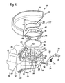
- FIG. 1 shows the front region of a hand-held power tool 10 designed as an angle grinder, whose elongate housing 12 determines a longitudinal axis 13 of the hand-held power tool 10.
- a gear housing 14 is flanged from the right angle to the longitudinal axis 13, an output shaft 16 occurs.
- a grinding wheel not shown, can be fastened, which is surrounded by a protective hood 43 to protect the hand tool 10 operators from flying chips or parts of the grinding wheel.
- the gear housing 14 is fixed to the housing 12 with flange screws 18 which engage in parallel to the longitudinal axis 13 extending flange holes 20 and it carries a bearing flange 22 which engages around the output shaft 16 in an annular manner.
- the bearing flange 22 is designed plate-like in the region facing the gear housing 14 and can be connected to the gear housing 14 via a flange screw connection 23 arranged substantially parallel to the output shaft 16.
- the bearing flange 22 protrudes at a right angle to the longitudinal axis 13 exiting cylindrical neck 24 which receives on its outer circumference, the protective cover 43 and the axially approximately centrally carries an annular groove 26, wherein its outer bead-like Ringnutbegrenzung 27 is traversed at regular intervals by axial grooves 28, the corresponding radial cams 46 are associated in the collar 44 of the protective hood 43 and are - to match - to couple in a plug-in rotary motion, such as a key-keyhole or bayonet lock system.
- the protective hood 43 consists of a disk-like, crescent-shaped base body 53 with a central hole 55, the outer edge 54 is angled and thereby extends teilzylindermantelartig.
- This main body 50 engages approximately half the circumference of a circular disk-shaped, not shown, abrasive body, which is driven by the output shaft 16 rotating, as usual with angle grinders.
- the main body 50 is connected to an annular collar 44, which has an edge region 45 bent laterally outwardly in the manner of a handle edge. This runs parallel to the perforated disc 52 of the main body 50 and concentric with the central hole 55 of the perforated disc 52nd
- the collar 44 is connectable to the body 50 by gluing, welding, brazing or the like. He has impressed, radially inwardly projecting radial cam 46. These agree dimensionally with the axial grooves 28 in the neck 24 of the bearing flange 22 so that they pass through axial plugging, then enter into the annular groove 26 by radial rotation and there the protective cover 43rd axially secured hold. In its hutrandartig angled area of the collar 44 carries locking openings 48, in the locking cams 32 of a locking lever 30 fit and enter and thus secure the guard 43 against rotation on the gear housing 14.
- the jonsite different widths and the matching height of the radial cam 46 are dimensionally matched to the matching, uniformly wide ring 26 and different widths of axial grooves 28 on the neck 24 tuned. It can be done with their collar axially over the neck 24 and attached to this operable only to each encodable grooved neck 24 matching protective hoods 43.
- a particular slotted spring ring-like annular spring 40 has to be pushed axially over the neck 24, wherein its spring cam 42 is to be guided by one of the axial grooves 28 and then - possibly after radial rotation - caulked in the annular groove 26 or by up or bending fixed in a pocket 41 on the lower edge of the neck 24 and thus secured against loss.
- the protective hood 43 is then guided with the radial cams 46 over the axial grooves 28 of the neck 24 until the radial cams 46 strike at the lower edge of the annular groove 26 and the protective hood 43 can only be rotated, the radial cams 46 being laterally bayonet-like into the annular groove 26 enter and hold it against axial emergence, axially biased and thus held backlash by the annular spring 40th
- the locking lever 30 has on its housing-side side above an area with locking cams 32, which are intended to engage in the latching openings 48.
- the locking lever 30 carries at one end to the locking cam 32 offset by about 90 extending bore through which a flange 18 is feasible to screw into a certain flange bore 20 and serves as a pivot axis 34 of the locking lever.
- Approximately in the middle of the locking lever 30 carries a transversely projecting, captive fastened compression spring 36 with which the locking lever 30 biased on the transmission housing 14 so supported that he always with a minimum force with its cams 32 at the bend 45 of the collar 44 can support and the entry of the locking cam 32 is secured in the locking openings 48.
- the main body 50 of the protective hood 43 has welding holes 53 through which the main body 50 can be welded or soldered to the collar 44 or to the angled portion 45.
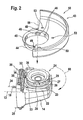
- Figure 2 shows how the figure 1, the three-dimensional view of the power tool 10 with the protective hood 43, wherein the protective cover 43 is completed and assembled by welding to the welding holes 53 and forms a unit with the collar 44.
- FIG. 2 shows an axial arrow 58, which accordingly pushes the protective hood 43 over the neck 24 and then turns it according to a rotary arrow 60 in such a way that the rounding of the main body 50 is rotated relative to the position shown.
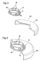
- FIG. 3 shows a further exemplary embodiment of a protective hood 430, which differs from the protective hood 43 of FIGS. 1 and 2 in that the collar 440 is made of plastic or metal, which engage with snap-in hooks 64 passing radially outwards into corresponding latching projections 65 of the main body 500 can by going through the central hole 51 is inserted and is fixed by latching, so that its angled, hutrandartiger area 66 comes to rest on the body 500.
- the detent openings 48 are arranged in this case in the base body 500, which must be correspondingly larger in size to accommodate the detent forces or holding forces for fixing the guard 24 on the gear housing 14 by the locking lever 30 can.
- FIG. 4 shows the protective hood 430 in the mounted state, wherein it can be seen that the snap hooks 64 are radially outward and overlap the base body 500 and secure against the collar 440.
- FIG. 5 shows a further exemplary embodiment of a demounted protective hood 432, the collar 441 of which is welded to the main body 501 and thus essentially corresponds to the protective hood 43 according to FIG.
- FIG. 6 shows the protective hood 432, which goes beyond the preceding figures, in that the welding holes 53 are welded to the collar 44.
- FIG. 7 shows a protective hood 434 whose collar ring 48 is made of plastic, which is injection-molded onto the main body 504 in the region of the central hole 51.
- Figure 8 shows a one-piece protective cover 433 made of steel, in which, as in Figure 7, the detent openings 48 in the main body 502 (504) are arranged, the advantage of this guard is that it can be produced in a single operation, albeit the cost of materials in this case is more complex than in the other variants.
Abstract
Claims (9)
- Machine-outil portative, en particulier meuleuse d'angle (10), avec un boîtier (12) allongé pour loger un moteur pour l'entraînement d'un arbre de sortie (16) coudé par rapport au boîtier (12), logé en rotation dans un boîtier d'engrenage (14) et qui sort de celui-ci par une extrémité libre prévue pour recevoir un corps de meulage, un capot de protection (43) entourant le corps de meulage qui peut être fixé au boîtier d'engrenage à vitesse variable et dont la position de rotation peut être bloquée au moyen d'un levier d'arrêt (30),
caractérisée en ce que
le levier d'arrêt (30) est disposé transversalement à l'axe longitudinal de la meuleuse d'angle (10) et pivotant autour d'un axe (34) pratiquement parallèle au boîtier (12). - Machine-outil portative selon la revendication 1,
caractérisée en ce que
le levier d'arrêt (30) est en contact avec le capot de protection (43) dans une position d'arrêt. - Machine-outil portative selon la revendication 1 ou 2,
caractérisée en ce que
le levier d'arrêt (30) est précontraint élastiquement en direction du capot de protection (43). - Machine-outil portative selon l'une quelconque des revendications 1 à 3,
caractérisée en ce que
le levier d'arrêt (30) présente des cames d'engagement (32) dirigées vers le centre du capot de protection ainsi qu'un bouton-poussoir (38). - Machine-outil portative selon l'une quelconque des revendications 1 à 4,
caractérisée en ce que
le levier d'arrêt (30) est fixé au boîtier (12, 14), en particulier au boîtier d'engrenage (14). - Machine-outil portative selon l'une quelconque des revendications 1 à 5,
caractérisée en ce que
le bouton-poussoir (38) du levier d'arrêt (30) fait saillie transversalement au boîtier d'engrenage (14) et de sa périphérie de façon à être accessible facilement par au moins un doigt, en particulier l'index, de la main d'actionnement entourant le boîtier (12) dans la position de travail. - Machine-outil portative selon l'une quelconque des revendications 1 à 6,
caractérisée en ce que
le boîtier d'engrenage (14) présente une bride d'engrenage (17) qui peut être vissée sur le boîtier (12), l'une des vis de bride (18) servant en même temps d'axe de pivotement (34) du levier d'arrêt (30). - Machine-outil portative selon l'une quelconque des revendications 1 à 7,
caractérisée en ce que
le capot de protection (43) peut être couplé par complémentarité de formes avec les cames d'engagement (32) du levier d'arrêt (30). - Machine-outil portative selon l'une quelconque des revendications 1 à 8,
caractérisée en ce que
le capot de protection (32) porte sur un cercle partiel des ouvertures d'engagement (48) dans lesquelles les cames d'engagement (32) du levier d'arrêt (30) peuvent s'enclencher.
Applications Claiming Priority (2)
| Application Number | Priority Date | Filing Date | Title |
|---|---|---|---|
| DE10343060A DE10343060A1 (de) | 2003-09-16 | 2003-09-16 | Handwerkzeugmaschine mit Schutzhaube |
| PCT/DE2004/001615 WO2005035190A1 (fr) | 2003-09-16 | 2004-07-22 | Machine-outil portative a capuchon protecteur |
Publications (2)
| Publication Number | Publication Date |
|---|---|
| EP1663575A1 EP1663575A1 (fr) | 2006-06-07 |
| EP1663575B1 true EP1663575B1 (fr) | 2008-01-02 |
Family
ID=34258729
Family Applications (1)
| Application Number | Title | Priority Date | Filing Date |
|---|---|---|---|
| EP04762465A Active EP1663575B1 (fr) | 2003-09-16 | 2004-07-22 | Machine-outil portative a capuchon protecteur |
Country Status (5)
| Country | Link |
|---|---|
| US (1) | US7063606B2 (fr) |
| EP (1) | EP1663575B1 (fr) |
| CN (1) | CN100515677C (fr) |
| DE (2) | DE10343060A1 (fr) |
| WO (1) | WO2005035190A1 (fr) |
Families Citing this family (62)
| Publication number | Priority date | Publication date | Assignee | Title |
|---|---|---|---|---|
| AUPQ618800A0 (en) * | 2000-03-10 | 2000-04-06 | Bayly Design Associates Pty Ltd | Power tool |
| DE10259520A1 (de) * | 2002-12-19 | 2004-07-01 | Robert Bosch Gmbh | Elektrohandwerkzeugmaschine |
| SE525836C2 (sv) * | 2003-03-31 | 2005-05-10 | Atlas Copco Tools Ab | Slipmaskin med sprängskydd och spindellåsning |
| DE102005000085A1 (de) * | 2005-07-05 | 2007-01-11 | Hilti Ag | Handwerkzeuggerät mit Schutzhaube |
| DE102005061867A1 (de) | 2005-12-23 | 2007-07-05 | Robert Bosch Gmbh | Schutzhaube mit Spannvorrichtung |
| DE102005063017B4 (de) * | 2005-12-30 | 2019-05-16 | Robert Bosch Gmbh | Handgeführtes Elektrowerkzeug mit einer Schutzhaube |
| DE102006022386A1 (de) * | 2006-05-12 | 2007-11-15 | Robert Bosch Gmbh | Schutzhaube für ein Handwerkzeug sowie Handwerkzeug mit Schutzhaube |
| DE102006027576A1 (de) * | 2006-06-14 | 2007-12-20 | Robert Bosch Gmbh | Schutzhauben-Befestigungsvorrichtung |
| DE502006006187D1 (de) | 2006-10-07 | 2010-04-01 | Metabowerke Gmbh | Elektrohandwerkzeuggerät, insbesondere ein Winkelschleifer mit einer Schutzhaube |
| DE102006053301A1 (de) * | 2006-11-13 | 2008-05-15 | Robert Bosch Gmbh | Handwerkzeugmaschine für ein rotierendes Werkzeug mit Schutzhaube |
| DE102007041840A1 (de) * | 2006-11-13 | 2008-05-15 | Robert Bosch Gmbh | Handwerkzeugmaschine mit Schutzhaube, insbesondere Winkelschleifer |
| DE102006053305A1 (de) | 2006-11-13 | 2008-05-15 | Robert Bosch Gmbh | Handwerkzeugmaschine mit Schutzhaube, insbesondere Winkelschleifer |
| DE102006053303A1 (de) * | 2006-11-13 | 2008-05-15 | Robert Bosch Gmbh | Handwerkzeugmaschine für ein rotierendes Werkzeug mit Schutzhaube |
| US7625265B2 (en) * | 2007-01-12 | 2009-12-01 | I.T., Inc. | Hood plates for handheld grinding tools |
| CN101264578B (zh) * | 2007-03-14 | 2010-11-24 | 苏州宝时得电动工具有限公司 | 动力工具 |
| CN101293330B (zh) * | 2007-04-28 | 2011-08-03 | 苏州宝时得电动工具有限公司 | 具有护罩的动力工具及其档位提示音装置 |
| DE102007000845A1 (de) * | 2007-10-11 | 2009-04-16 | Hilti Aktiengesellschaft | Handwerkzeugmaschine |
| DE102007052685A1 (de) | 2007-11-05 | 2009-05-07 | Robert Bosch Gmbh | Handwerkzeugmaschine |
| DE102007052683A1 (de) | 2007-11-05 | 2009-05-07 | Robert Bosch Gmbh | Handwerkzeugmaschine |
| DE102007052684A1 (de) | 2007-11-05 | 2009-05-07 | Robert Bosch Gmbh | Handwerkzeugmaschine |
| DE102007057032A1 (de) | 2007-11-27 | 2009-05-28 | Robert Bosch Gmbh | Handwerkzeugmaschine |
| DE102008010977A1 (de) * | 2008-02-25 | 2009-08-27 | Robert Bosch Gmbh | Handwerkzeugmaschine, insbesondere handgeführte Schleifmaschine |
| DE102008000732A1 (de) * | 2008-03-18 | 2009-09-24 | Robert Bosch Gmbh | Handwerkzeugmaschine, insbesondere handgeführte Schleifmaschine |
| DE102008002548B4 (de) * | 2008-06-20 | 2021-11-11 | Robert Bosch Gmbh | Werkzeugmaschine, insbesondere Handwerkzeugmaschine |
| DE102008040372A1 (de) * | 2008-07-11 | 2010-01-21 | Robert Bosch Gmbh | Schutzhaubenverdrehsicherungsvorrichtung |
| DE102008040369B4 (de) * | 2008-07-11 | 2021-09-23 | Robert Bosch Gmbh | Schutzhaubenverdrehsicherungsvorrichtung |
| KR101005987B1 (ko) * | 2008-07-15 | 2011-01-05 | 계양전기 주식회사 | 휠 가드의 조절이 용이한 전동 공구 |
| DE102009017299A1 (de) * | 2009-04-11 | 2010-10-21 | Metabowerke Gmbh | Schutzhaube für Elektrohandwerkzeuggeräte und Elektrohandwerkzeuggerät |
| JP5297392B2 (ja) * | 2009-07-06 | 2013-09-25 | 株式会社マキタ | サンダー |
| DE102009028404A1 (de) * | 2009-08-10 | 2011-02-17 | Robert Bosch Gmbh | Werkzeugmaschine mit einer Schutzhaube |
| JP5544867B2 (ja) * | 2009-12-21 | 2014-07-09 | 日立工機株式会社 | グラインダ |
| CN201711848U (zh) * | 2010-02-09 | 2011-01-19 | 南京德朔实业有限公司 | 一种动力工具 |
| KR101220750B1 (ko) | 2010-07-06 | 2013-01-09 | 계양전기 주식회사 | 위치 조절이 용이한 더스트 후드 조립체 및 이러한 더스트 후드 조립체를 구비한 전동공구 |
| DE102010038509A1 (de) * | 2010-07-28 | 2012-02-02 | Robert Bosch Gmbh | Handwerkzeugmaschine |
| JP5684056B2 (ja) * | 2010-08-16 | 2015-03-11 | 株式会社マキタ | 手持ち工具 |
| DE102010044613A1 (de) * | 2010-09-01 | 2012-03-01 | C. & E. Fein Gmbh | Schleifgerät |
| JP2012213820A (ja) * | 2011-03-31 | 2012-11-08 | Makita Corp | 電動工具 |
| JP5760658B2 (ja) * | 2011-04-29 | 2015-08-12 | 日立工機株式会社 | 携帯型作業機 |
| US9120202B2 (en) | 2011-06-30 | 2015-09-01 | Black & Decker Inc. | Shield assembly for a power tool |
| JP5959421B2 (ja) * | 2011-12-14 | 2016-08-02 | 株式会社マキタ | グラインダ |
| DE102012210759A1 (de) * | 2012-06-25 | 2014-01-02 | Robert Bosch Gmbh | Schutzhaubenvorrichtung |
| ES2648494T3 (es) * | 2012-09-18 | 2018-01-03 | Ingersoll-Rand Company | Amoladora con protectores |
| DE102012222602A1 (de) * | 2012-12-10 | 2014-06-26 | Robert Bosch Gmbh | Elektrische Maschine |
| DE102013210962B4 (de) * | 2013-06-12 | 2016-08-04 | Robert Bosch Gmbh | Handwerkzeugmaschine mit einem elektromotorischen Antrieb und mindestens einem ersten Gehäuseteil |
| US10011009B2 (en) * | 2013-11-01 | 2018-07-03 | Robert Bosch Tool Corporation | Guide foot for an oscillating power tool |
| US10201889B2 (en) * | 2014-08-06 | 2019-02-12 | Sparky Guard, LLC | Fully rotatable grinder guard assembly and method for making same |
| KR101625449B1 (ko) | 2015-03-31 | 2016-05-31 | 계양전기 주식회사 | 그라인더 휠가드의 고정구조 |
| US11338426B2 (en) | 2015-11-02 | 2022-05-24 | Black & Decker, Inc. | Cordless power cutter |
| EP3173189A1 (fr) * | 2015-11-25 | 2017-05-31 | HILTI Aktiengesellschaft | Tronçonneuse portative manuelle |
| EP3251791B1 (fr) | 2016-05-06 | 2019-03-27 | Black & Decker Inc. | Levier réversible pour un ensemble de protection d'un outil électrique |
| US10406718B2 (en) * | 2017-03-17 | 2019-09-10 | G.A.W. Inc | Guard and control apparatus for safe operation of a rotary cutter |
| EP3412188A1 (fr) * | 2017-06-06 | 2018-12-12 | HILTI Aktiengesellschaft | Buse d'aspiration pour une fraiseuse à main |
| JP7089326B2 (ja) * | 2018-02-21 | 2022-06-22 | 株式会社マキタ | 電動工具 |
| JP2020006483A (ja) * | 2018-07-09 | 2020-01-16 | 株式会社マキタ | 電動工具 |
| JP7110025B2 (ja) * | 2018-08-07 | 2022-08-01 | 株式会社マキタ | 電動工具 |
| TWI723507B (zh) * | 2019-08-22 | 2021-04-01 | 車王電子股份有限公司 | 電動工具之防護裝置 |
| DE202019105846U1 (de) * | 2019-10-21 | 2021-01-22 | C. & E. Fein Gmbh | Elektrohandwerkzeugmaschine |
| CN112775793B (zh) * | 2021-01-28 | 2022-01-04 | 河南省润领信息科技有限公司 | 一种环保机械加工用打磨装置 |
| KR102567445B1 (ko) * | 2021-04-16 | 2023-08-18 | 주식회사 아임삭 | 휠커버를 갖는 그라인더 |
| CN116133813A (zh) * | 2021-08-06 | 2023-05-16 | 百得有限公司 | 具有护罩的圆锯 |
| CN117086387B (zh) * | 2023-10-20 | 2023-12-19 | 成都市凯林机械贸易有限责任公司 | 一种具有保护结构的切割设备 |
| CN117381050A (zh) * | 2023-11-27 | 2024-01-12 | 佛山市艾倍科五金有限公司 | 基于废屑导流的五金配件手持切割装置及其使用方法 |
Family Cites Families (13)
| Publication number | Priority date | Publication date | Assignee | Title |
|---|---|---|---|---|
| US4060940A (en) | 1976-01-13 | 1977-12-06 | The Black And Decker Manufacturing Company | Adjustable guard construction for cut-off machine |
| DE3338917A1 (de) * | 1983-10-27 | 1985-05-09 | C. & E. Fein Gmbh & Co, 7000 Stuttgart | Schutzhaubenbefestigung fuer tragbare winkelschleifer |
| DE3636601A1 (de) * | 1986-10-28 | 1988-05-05 | Bosch Gmbh Robert | Schutzhaube fuer schleifmaschinen, insbesondere winkelschleifer, und dazu passende befestigungsaufnahme auf diese |
| DE3638337A1 (de) * | 1986-11-10 | 1988-05-19 | Licentia Gmbh | Spannvorrichtung fuer die schutzhaube von winkelschleifern od. dergl. elektrowerkzeuge |
| DE3940584A1 (de) * | 1989-12-08 | 1991-06-13 | Bosch Gmbh Robert | Schutzhaube fuer handwerkzeugmaschinen, insbesondere schleifmaschinen |
| US5440815A (en) * | 1992-04-13 | 1995-08-15 | Inkster; Kevin R. | Guide for rotary cutter tools |
| SE507264C2 (sv) * | 1996-06-13 | 1998-05-04 | Atlas Copco Tools Ab | Handhållet motordrivet verktyg |
| DE19829190B4 (de) * | 1998-06-30 | 2006-12-21 | Robert Bosch Gmbh | Handschleifmaschine |
| DE19914855B4 (de) * | 1999-04-01 | 2004-04-22 | Metabowerke Gmbh | Handschleifmaschine mit einer in Umfangsrichtung verstellbaren Schutzhaube |
| DE10000701A1 (de) * | 2000-01-10 | 2001-07-12 | Bosch Gmbh Robert | Winkelschleiferschutzhaube |
| US6464573B1 (en) * | 2000-06-30 | 2002-10-15 | Porter-Cable Corporation | Guard attachment system with knurled clamp ring |
| US6699114B1 (en) * | 2002-04-26 | 2004-03-02 | Benedict Engineering Company, Inc. | Pivotal guards for power hand tools with rotating discs |
| CN2557286Y (zh) * | 2002-07-30 | 2003-06-25 | 阿特拉斯·科普柯长春电动工具有限公司 | 角向磨光机 |
-
2003
- 2003-09-16 DE DE10343060A patent/DE10343060A1/de not_active Withdrawn
-
2004
- 2004-07-22 CN CNB2004800267784A patent/CN100515677C/zh active Active
- 2004-07-22 US US10/522,975 patent/US7063606B2/en active Active
- 2004-07-22 WO PCT/DE2004/001615 patent/WO2005035190A1/fr active IP Right Grant
- 2004-07-22 EP EP04762465A patent/EP1663575B1/fr active Active
- 2004-07-22 DE DE502004005855T patent/DE502004005855D1/de active Active
Also Published As
| Publication number | Publication date |
|---|---|
| DE502004005855D1 (de) | 2008-02-14 |
| CN1852785A (zh) | 2006-10-25 |
| EP1663575A1 (fr) | 2006-06-07 |
| DE10343060A1 (de) | 2005-04-07 |
| US20050215186A1 (en) | 2005-09-29 |
| WO2005035190A1 (fr) | 2005-04-21 |
| CN100515677C (zh) | 2009-07-22 |
| US7063606B2 (en) | 2006-06-20 |
Similar Documents
| Publication | Publication Date | Title |
|---|---|---|
| EP1663575B1 (fr) | Machine-outil portative a capuchon protecteur | |
| EP2104590B1 (fr) | Dispositif anti-rotation pour un capot de protection | |
| EP2097220B1 (fr) | Machine-outil manuelle pour un outil rotatif à capot protecteur | |
| EP0836544B1 (fr) | Meuleuse portative electrique | |
| EP1575740B1 (fr) | Machine-outil electrique a main | |
| EP0569370B1 (fr) | Outil electrique a main | |
| EP0583270B1 (fr) | Outillage electrique a main | |
| EP1618990B1 (fr) | Outil motorisé portatif, en particulier meuleuse d'angle | |
| DE19618954A1 (de) | Einstellbare Schutzvorrichtung für motorgetriebene Werkzeuge | |
| WO2004039541A1 (fr) | Machine-outil manuelle comprenant une poignee rotative a amortissement de vibrations | |
| EP2209591B1 (fr) | Machine-outil portative | |
| EP1341632B1 (fr) | Machine-outil portative comportant deux meules de decoupage tournant en sens contraire directement de maniere adjacente et des elements pour monter les meules de decoupage pour une telle machine-outil portative | |
| EP2608930B1 (fr) | Machine-outil portative à col de serrage | |
| EP1701820A1 (fr) | Machine-outil manuelle a dispositif de serrage | |
| DE4432973B4 (de) | Elektrische Handwerkzeugmaschine mit einer Spindelarretierung | |
| DE19914855B4 (de) | Handschleifmaschine mit einer in Umfangsrichtung verstellbaren Schutzhaube | |
| DE102008002548B4 (de) | Werkzeugmaschine, insbesondere Handwerkzeugmaschine | |
| DE4344128A1 (de) | Elektrische Handwerkzeugmaschine | |
| DE19632218B4 (de) | Schwingschleifer | |
| DE19518854A1 (de) | Handgeführte Elektrowerkzeugmaschine, insbesondere Winkelschleifmaschine | |
| DE102010038509A1 (de) | Handwerkzeugmaschine | |
| DE20321233U1 (de) | Handwerkzeugmaschine mit Schutzhaube | |
| EP1741521B1 (fr) | Outil portatif avec bonnet de protection | |
| DE102017213747A1 (de) | Schutzvorrichtung für eine Handwerkzeugmaschine | |
| WO1992012823A1 (fr) | Outilage a main |
Legal Events
| Date | Code | Title | Description |
|---|---|---|---|
| PUAI | Public reference made under article 153(3) epc to a published international application that has entered the european phase |
Free format text: ORIGINAL CODE: 0009012 |
|
| 17P | Request for examination filed |
Effective date: 20060418 |
|
| AK | Designated contracting states |
Kind code of ref document: A1 Designated state(s): DE FR GB |
|
| RBV | Designated contracting states (corrected) |
Designated state(s): DE FR GB |
|
| DAX | Request for extension of the european patent (deleted) | ||
| RBV | Designated contracting states (corrected) |
Designated state(s): DE FR GB |
|
| GRAP | Despatch of communication of intention to grant a patent |
Free format text: ORIGINAL CODE: EPIDOSNIGR1 |
|
| GRAS | Grant fee paid |
Free format text: ORIGINAL CODE: EPIDOSNIGR3 |
|
| GRAA | (expected) grant |
Free format text: ORIGINAL CODE: 0009210 |
|
| AK | Designated contracting states |
Kind code of ref document: B1 Designated state(s): DE FR GB |
|
| REG | Reference to a national code |
Ref country code: GB Ref legal event code: FG4D Free format text: NOT ENGLISH |
|
| REF | Corresponds to: |
Ref document number: 502004005855 Country of ref document: DE Date of ref document: 20080214 Kind code of ref document: P |
|
| GBT | Gb: translation of ep patent filed (gb section 77(6)(a)/1977) |
Effective date: 20080501 |
|
| ET | Fr: translation filed | ||
| PLBE | No opposition filed within time limit |
Free format text: ORIGINAL CODE: 0009261 |
|
| STAA | Information on the status of an ep patent application or granted ep patent |
Free format text: STATUS: NO OPPOSITION FILED WITHIN TIME LIMIT |
|
| 26N | No opposition filed |
Effective date: 20081003 |
|
| REG | Reference to a national code |
Ref country code: FR Ref legal event code: PLFP Year of fee payment: 13 |
|
| REG | Reference to a national code |
Ref country code: FR Ref legal event code: PLFP Year of fee payment: 14 |
|
| REG | Reference to a national code |
Ref country code: FR Ref legal event code: PLFP Year of fee payment: 15 |
|
| PGFP | Annual fee paid to national office [announced via postgrant information from national office to epo] |
Ref country code: GB Payment date: 20210722 Year of fee payment: 18 |
|
| PGFP | Annual fee paid to national office [announced via postgrant information from national office to epo] |
Ref country code: FR Payment date: 20220725 Year of fee payment: 19 |
|
| GBPC | Gb: european patent ceased through non-payment of renewal fee |
Effective date: 20220722 |
|
| PG25 | Lapsed in a contracting state [announced via postgrant information from national office to epo] |
Ref country code: GB Free format text: LAPSE BECAUSE OF NON-PAYMENT OF DUE FEES Effective date: 20220722 |
|
| REG | Reference to a national code |
Ref country code: DE Ref legal event code: R084 Ref document number: 502004005855 Country of ref document: DE |
|
| PGFP | Annual fee paid to national office [announced via postgrant information from national office to epo] |
Ref country code: DE Payment date: 20230922 Year of fee payment: 20 |