EP1663575B1 - Portable power tool with protective cover - Google Patents
Portable power tool with protective cover Download PDFInfo
- Publication number
- EP1663575B1 EP1663575B1 EP04762465A EP04762465A EP1663575B1 EP 1663575 B1 EP1663575 B1 EP 1663575B1 EP 04762465 A EP04762465 A EP 04762465A EP 04762465 A EP04762465 A EP 04762465A EP 1663575 B1 EP1663575 B1 EP 1663575B1
- Authority
- EP
- European Patent Office
- Prior art keywords
- housing
- hand
- machine tool
- protective hood
- latching lever
- Prior art date
- Legal status (The legal status is an assumption and is not a legal conclusion. Google has not performed a legal analysis and makes no representation as to the accuracy of the status listed.)
- Expired - Lifetime
Links
- 230000001681 protective effect Effects 0.000 title claims abstract description 57
- 230000005540 biological transmission Effects 0.000 abstract description 6
- 238000003466 welding Methods 0.000 description 5
- 239000000463 material Substances 0.000 description 4
- 239000002184 metal Substances 0.000 description 3
- 230000006835 compression Effects 0.000 description 2
- 238000007906 compression Methods 0.000 description 2
- 230000033001 locomotion Effects 0.000 description 2
- 229910000831 Steel Inorganic materials 0.000 description 1
- 238000004026 adhesive bonding Methods 0.000 description 1
- 238000005452 bending Methods 0.000 description 1
- 238000005219 brazing Methods 0.000 description 1
- 238000010276 construction Methods 0.000 description 1
- 239000000428 dust Substances 0.000 description 1
- 230000001771 impaired effect Effects 0.000 description 1
- 238000009434 installation Methods 0.000 description 1
- 239000010959 steel Substances 0.000 description 1
Images


Classifications
-
- B—PERFORMING OPERATIONS; TRANSPORTING
- B24—GRINDING; POLISHING
- B24B—MACHINES, DEVICES, OR PROCESSES FOR GRINDING OR POLISHING; DRESSING OR CONDITIONING OF ABRADING SURFACES; FEEDING OF GRINDING, POLISHING, OR LAPPING AGENTS
- B24B55/00—Safety devices for grinding or polishing machines; Accessories fitted to grinding or polishing machines for keeping tools or parts of the machine in good working condition
- B24B55/04—Protective covers for the grinding wheel
- B24B55/05—Protective covers for the grinding wheel specially designed for portable grinding machines
- B24B55/052—Protective covers for the grinding wheel specially designed for portable grinding machines with rotating tools
-
- B—PERFORMING OPERATIONS; TRANSPORTING
- B24—GRINDING; POLISHING
- B24B—MACHINES, DEVICES, OR PROCESSES FOR GRINDING OR POLISHING; DRESSING OR CONDITIONING OF ABRADING SURFACES; FEEDING OF GRINDING, POLISHING, OR LAPPING AGENTS
- B24B23/00—Portable grinding machines, e.g. hand-guided; Accessories therefor
- B24B23/02—Portable grinding machines, e.g. hand-guided; Accessories therefor with rotating grinding tools; Accessories therefor
Definitions
- the present invention is based on a hand tool according to the preamble of claim 1.
- a hand tool machine which is designed as an angle grinder and which is provided with a protective hood whose rotational position in the circumferential direction with a simple, releasable locking mechanism can be fixed.
- Its locking member consists essentially of a leaf spring, whose projections for adjusting the guard by hand out of engagement with depressions of the protective cover can be brought and their locking forces are impaired under hard construction site operation by deformation of the locking member.
- the invention with the features of claim 1 has the advantage that on conventional hand tool machines, especially angle grinders without constructive change a protective hood with associated robust, simple guard lock is installed with the guard in each rotational position can be reliably fixed.
- the latching lever is arranged transversely to the longitudinal axis of the angle grinder and pivotable about an axis arranged substantially parallel to the housing, the movement paths of the locking lever are fixed and thus preclude changes in the locking characteristic of the protective hood.
- the protective hood can be locked in a force-locking or positive-locking manner in this position.
- the detent lever at the free end carries a pushbutton and at the other end and / or centrally at least one locking cam, which engages in the protective hood and This holds form-fitting, an easy-to-use, robust and accurate locking means is created.
- the push button of the locking lever projects transversely to the transmission housing and beyond its circumference, it is easily accessible for at least one finger, in particular the index finger of the housing in working position encompassing the protective cover is comfortable and quickly adjustable and incorrect operation excluded.
- the protective cover can be brought into positive engagement with the rigid locking cams, a largely backlash-free, secure against unwanted release positioning of the protective cover in any rotational position is possible.
- the gear housing has a flange which can be screwed to the housing, wherein one of the flanged screws also serves as the axis of rotation of the locking lever, the locking means of the angle grinder protective hood can be easily attached to conventional angle grinder.
- the protective hood has detent openings for engagement of detent cams of the detent lever on a pitch circle, a secure, positive locking of the protective hood in predetermined rotational positions relative to the handheld power tool is possible.
- the protective cover is formed in several parts, wherein the first part is a ring-like collar, in particular with angled edge region, made of strong material, and a second part is a disk-like body, the protective cover of different materials is particularly inexpensive to produce, because the parts independently mutually cheaper machinable and the protective cover can be produced as a lightweight component.
- the annular collar part has an angled, edge-like region which carries the latching openings
- the second part namely the protective hood body, be made of a particularly thin material, because only the collar part absorbs the locking forces between the locking openings and the locking cams of the locking lever.
- the fastening area of the gear housing which carries the protective cover can be made of relatively coarsely tolerated plastic, because the ring leaf spring Dimensional deviations or wear in the mounting area compensates.
- the transmission housing has a designed as a cylindrical plastic neck mounting portion for the guard, which belongs to a drive shaft concentrically surrounding the bearing flange, weight can be saved on the gear housing and thus on the entire hand tool, so that the hand tool is handy and can be handled without tiring ,
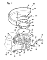
- FIG. 1 shows the front region of a hand-held power tool 10 designed as an angle grinder, whose elongate housing 12 determines a longitudinal axis 13 of the hand-held power tool 10.
- a gear housing 14 is flanged from the right angle to the longitudinal axis 13, an output shaft 16 occurs.
- a grinding wheel not shown, can be fastened, which is surrounded by a protective hood 43 to protect the hand tool 10 operators from flying chips or parts of the grinding wheel.
- the gear housing 14 is fixed to the housing 12 with flange screws 18 which engage in parallel to the longitudinal axis 13 extending flange holes 20 and it carries a bearing flange 22 which engages around the output shaft 16 in an annular manner.
- the bearing flange 22 is designed plate-like in the region facing the gear housing 14 and can be connected to the gear housing 14 via a flange screw connection 23 arranged substantially parallel to the output shaft 16.
- the bearing flange 22 protrudes at a right angle to the longitudinal axis 13 exiting cylindrical neck 24 which receives on its outer circumference, the protective cover 43 and the axially approximately centrally carries an annular groove 26, wherein its outer bead-like Ringnutbegrenzung 27 is traversed at regular intervals by axial grooves 28, the corresponding radial cams 46 are associated in the collar 44 of the protective hood 43 and are - to match - to couple in a plug-in rotary motion, such as a key-keyhole or bayonet lock system.
- the protective hood 43 consists of a disk-like, crescent-shaped base body 53 with a central hole 55, the outer edge 54 is angled and thereby extends teilzylindermantelartig.
- This main body 50 engages approximately half the circumference of a circular disk-shaped, not shown, abrasive body, which is driven by the output shaft 16 rotating, as usual with angle grinders.
- the main body 50 is connected to an annular collar 44, which has an edge region 45 bent laterally outwardly in the manner of a handle edge. This runs parallel to the perforated disc 52 of the main body 50 and concentric with the central hole 55 of the perforated disc 52nd
- the collar 44 is connectable to the body 50 by gluing, welding, brazing or the like. He has impressed, radially inwardly projecting radial cam 46. These agree dimensionally with the axial grooves 28 in the neck 24 of the bearing flange 22 so that they pass through axial plugging, then enter into the annular groove 26 by radial rotation and there the protective cover 43rd axially secured hold. In its hutrandartig angled area of the collar 44 carries locking openings 48, in the locking cams 32 of a locking lever 30 fit and enter and thus secure the guard 43 against rotation on the gear housing 14.
- the jonsite different widths and the matching height of the radial cam 46 are dimensionally matched to the matching, uniformly wide ring 26 and different widths of axial grooves 28 on the neck 24 tuned. It can be done with their collar axially over the neck 24 and attached to this operable only to each encodable grooved neck 24 matching protective hoods 43.
- a particular slotted spring ring-like annular spring 40 has to be pushed axially over the neck 24, wherein its spring cam 42 is to be guided by one of the axial grooves 28 and then - possibly after radial rotation - caulked in the annular groove 26 or by up or bending fixed in a pocket 41 on the lower edge of the neck 24 and thus secured against loss.
- the protective hood 43 is then guided with the radial cams 46 over the axial grooves 28 of the neck 24 until the radial cams 46 strike at the lower edge of the annular groove 26 and the protective hood 43 can only be rotated, the radial cams 46 being laterally bayonet-like into the annular groove 26 enter and hold it against axial emergence, axially biased and thus held backlash by the annular spring 40th
- the locking lever 30 has on its housing-side side above an area with locking cams 32, which are intended to engage in the latching openings 48.
- the locking lever 30 carries at one end to the locking cam 32 offset by about 90 extending bore through which a flange 18 is feasible to screw into a certain flange bore 20 and serves as a pivot axis 34 of the locking lever.
- Approximately in the middle of the locking lever 30 carries a transversely projecting, captive fastened compression spring 36 with which the locking lever 30 biased on the transmission housing 14 so supported that he always with a minimum force with its cams 32 at the bend 45 of the collar 44 can support and the entry of the locking cam 32 is secured in the locking openings 48.
- the main body 50 of the protective hood 43 has welding holes 53 through which the main body 50 can be welded or soldered to the collar 44 or to the angled portion 45.
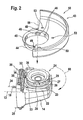
- Figure 2 shows how the figure 1, the three-dimensional view of the power tool 10 with the protective hood 43, wherein the protective cover 43 is completed and assembled by welding to the welding holes 53 and forms a unit with the collar 44.
- FIG. 2 shows an axial arrow 58, which accordingly pushes the protective hood 43 over the neck 24 and then turns it according to a rotary arrow 60 in such a way that the rounding of the main body 50 is rotated relative to the position shown.
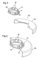
- FIG. 3 shows a further exemplary embodiment of a protective hood 430, which differs from the protective hood 43 of FIGS. 1 and 2 in that the collar 440 is made of plastic or metal, which engage with snap-in hooks 64 passing radially outwards into corresponding latching projections 65 of the main body 500 can by going through the central hole 51 is inserted and is fixed by latching, so that its angled, hutrandartiger area 66 comes to rest on the body 500.
- the detent openings 48 are arranged in this case in the base body 500, which must be correspondingly larger in size to accommodate the detent forces or holding forces for fixing the guard 24 on the gear housing 14 by the locking lever 30 can.
- FIG. 4 shows the protective hood 430 in the mounted state, wherein it can be seen that the snap hooks 64 are radially outward and overlap the base body 500 and secure against the collar 440.
- FIG. 5 shows a further exemplary embodiment of a demounted protective hood 432, the collar 441 of which is welded to the main body 501 and thus essentially corresponds to the protective hood 43 according to FIG.
- FIG. 6 shows the protective hood 432, which goes beyond the preceding figures, in that the welding holes 53 are welded to the collar 44.
- FIG. 7 shows a protective hood 434 whose collar ring 48 is made of plastic, which is injection-molded onto the main body 504 in the region of the central hole 51.
- Figure 8 shows a one-piece protective cover 433 made of steel, in which, as in Figure 7, the detent openings 48 in the main body 502 (504) are arranged, the advantage of this guard is that it can be produced in a single operation, albeit the cost of materials in this case is more complex than in the other variants.
Landscapes
- Engineering & Computer Science (AREA)
- Mechanical Engineering (AREA)
- Grinding-Machine Dressing And Accessory Apparatuses (AREA)
- Finish Polishing, Edge Sharpening, And Grinding By Specific Grinding Devices (AREA)
Abstract
Description
Die vorliegende Erfindung geht aus von einer Handwerkzeugmaschine nach dem Oberbegriff des Anspruchs 1.The present invention is based on a hand tool according to the preamble of claim 1.
Aus der
Die Erfindung mit den Merkmalen des Anspruchs 1 hat den Vorteil, dass an herkömmlichen Handwerkzeugmaschinen, insbesondere Winkelschleifern, ohne konstruktive Veränderung eine Schutzhaube mit zugehöriger robuster, einfacher Schutzhaubenarretierung einbaubar ist, mit der die Schutzhaube in jeder Drehposition zuverlässig festlegbar ist.The invention with the features of claim 1 has the advantage that on conventional hand tool machines, especially angle grinders without constructive change a protective hood with associated robust, simple guard lock is installed with the guard in each rotational position can be reliably fixed.
Dadurch, dass der Rasthebel quer zur Längsachse des Winkelschleifers angeordnet und um eine im wesentlichen parallel zum Gehäuse angeordnete Achse schwenkbar ist, sind die Bewegungsbahnen des Rasthebels festgelegt und damit Veränderungen in der Arretiercharakteristik der Schutzhaube auszuschließen.Characterized in that the latching lever is arranged transversely to the longitudinal axis of the angle grinder and pivotable about an axis arranged substantially parallel to the housing, the movement paths of the locking lever are fixed and thus preclude changes in the locking characteristic of the protective hood.
Dadurch, dass der Rasthebel in einer Rastposition die Schutzhaube berührt, ist in dieser Position die Schutzhaube kraft- oder formschlüssig sicherbar.Due to the fact that the detent lever touches the protective hood in a detent position, the protective hood can be locked in a force-locking or positive-locking manner in this position.
Dadurch, dass der Rasthebel zur Schutzhaube weisend elastisch vorgespannt ist, ist ein ständiger Kontakt zwischen dem Rasthebel und der Schutzhaube gesichert.Characterized in that the locking lever is biased elastically facing the protective cover, a constant contact between the locking lever and the guard is secured.
Dadurch, dass der Rasthebel am freien Ende eine Drucktaste und am anderen Ende und/oder mittig mindestens einen Rastnocken trägt, der in die Schutzhaube eingreift und diese formschlüssig festhält, ist ein einfach bedienbares, robustes und genaues Rastmittel geschaffen.Characterized in that the detent lever at the free end carries a pushbutton and at the other end and / or centrally at least one locking cam, which engages in the protective hood and This holds form-fitting, an easy-to-use, robust and accurate locking means is created.
Dadurch, dass der Rasthebel am Gehäuse, insbesondere am Getriebegehäuse, schwenkbar gelagert ist, sind Funktion und Montage des Rasthebels nur durch Lösen und neu Verschrauben einer Flanschschraube herstellbar.Characterized in that the locking lever on the housing, in particular on the gear housing, is pivotally mounted, function and installation of the locking lever can be produced only by loosening and re-screwing a flange.
Dadurch, dass die Drucktaste des Rasthebels quer zum Getriebegehäuse und über dessen Umfang hinaussteht, ist sie leicht zugänglich für mindestens einen Finger, insbesondere den Zeigefinger der das Gehäuse in Arbeitsposition umgreifenden Bedienhand ist die Schutzhaube bequem und schnell einstellbar und Fehlbedienung ausgeschlossen.The fact that the push button of the locking lever projects transversely to the transmission housing and beyond its circumference, it is easily accessible for at least one finger, in particular the index finger of the housing in working position encompassing the protective cover is comfortable and quickly adjustable and incorrect operation excluded.
Dadurch, dass die Schutzhaube formschlüssig mit den starren Rastnocken in Eingriff bringbar ist, ist eine weitgehend spielfreie, gegen ungewolltes Lösen sichere Positionierung der Schutzhaube in beliebigen Drehpositionen möglich.Because the protective cover can be brought into positive engagement with the rigid locking cams, a largely backlash-free, secure against unwanted release positioning of the protective cover in any rotational position is possible.
Dadurch, dass das Getriebegehäuse einen Flansch hat, der an das Gehäuse schraubbar ist, wobei eine der Flansschrauben zugleich als Drehachse des Rasthebels dient, sind die Arretiermittel der Winkelschleiferschutzhaube leicht an herkömmliche Winkelschleifer anbaubar.The fact that the gear housing has a flange which can be screwed to the housing, wherein one of the flanged screws also serves as the axis of rotation of the locking lever, the locking means of the angle grinder protective hood can be easily attached to conventional angle grinder.
Dadurch, dass die Schutzhaube auf einem Teilkreis Rastöffnungen zum Eingriff von Rastnocken des Rasthebels aufweist, ist eine sichere, formschlüssige Arretierung der Schutzhaube in vorbestimmten Drehpositionen gegenüber der Handwerkzeugmaschine möglich.Due to the fact that the protective hood has detent openings for engagement of detent cams of the detent lever on a pitch circle, a secure, positive locking of the protective hood in predetermined rotational positions relative to the handheld power tool is possible.
Dadurch, dass die Schutzhaube mehrteilig ausgebildet ist, wobei als erster Teil ein ringartiger Kragen, insbesondere mit abgewinkeltem Randbereich, aus starkem Material besteht, und ein zweiter Teil ein scheibenartiger Grundkörper ist, ist die Schutzhaube aus unterschiedlichen Werkstoffen besonders kostengünstig herstellbar, weil die Teile unabhängig voneinander günstiger bearbeitbar sind und die Schutzhaube als Leichtbauteil herstellbar ist.Characterized in that the protective cover is formed in several parts, wherein the first part is a ring-like collar, in particular with angled edge region, made of strong material, and a second part is a disk-like body, the protective cover of different materials is particularly inexpensive to produce, because the parts independently mutually cheaper machinable and the protective cover can be produced as a lightweight component.
Dadurch, dass der ringartige Kragenteil einen abgewinkelten, hutrandartigen Bereich aufweist, der die Rastöffnungen trägt, kann der zweite Teil, nämlich der Schutzhaubengrundkörper, aus besonders dünnem Material gefertigt sein, weil allein das Kragenteil die Arretierungskräfte zwischen den Rastöffnungen und den Rastnocken des Rasthebels aufnimmt.Characterized in that the annular collar part has an angled, edge-like region which carries the latching openings, the second part, namely the protective hood body, be made of a particularly thin material, because only the collar part absorbs the locking forces between the locking openings and the locking cams of the locking lever.
Dadurch, dass im Befestigungsbereich der Winkelschleiferschutzhaube am Hals des Getriebegehäuses eine Ringblattfeder vorgesehen ist, die die Schutzhaube axial spielfrei radial drehbar am Getriebegehäuse hält, kann der Befestigungsbereich des Getriebegehäuses, der die Schutzhaube trägt, aus verhältnismäßig grob toleriertem Kunststoff bestehen, weil die Ring-Blattfeder Maßabweichungen bzw. Verschleiß im Befestigungsbereich ausgleicht.Due to the fact that a ring leaf spring is provided in the fastening area of the angle grinder protective hood at the neck of the gear housing, which rotatably holds the protective cover axially rotatable on the transmission housing, the fastening area of the gear housing which carries the protective cover can be made of relatively coarsely tolerated plastic, because the ring leaf spring Dimensional deviations or wear in the mounting area compensates.
Dadurch, dass das Getriebegehäuse einen als zylindrischen Kunststoffhals ausgestalteten Befestigungsbereich für die Schutzhaube hat, der zu einem die Abtriebswelle konzentrisch umgreifenden Lagerflansch gehört, kann am Getriebegehäuse und damit an der gesamten Handwerkzeugmaschine Gewicht eingespart werden, so dass die Handwerkzeugmaschine handlicher ist und ermüdungsfrei gehandhabt werden kann.Characterized in that the transmission housing has a designed as a cylindrical plastic neck mounting portion for the guard, which belongs to a drive shaft concentrically surrounding the bearing flange, weight can be saved on the gear housing and thus on the entire hand tool, so that the hand tool is handy and can be handled without tiring ,
Nachstehend ist die Erfindung anhand eines Ausführungsbeispiels mit zugehörigen Zeichnungen näher erläutert.The invention with reference to an embodiment with accompanying drawings is explained in more detail.
Es zeigen
- Figur 1
- die Handwerkzeugmaschine mit Schutzhaube in Explosionsdarstellung,
- Figur 2
- die Handwerkzeugmaschine gemäß Figur 1 mit zusammengebauter Schutzhaube vor dem Zusammenfügen,
- Figur 3
- die Einzelteile eines zweiteiligen Ausführungsbeispiels der Schutzhaube
- Figur 4
- die Schutzhaube gemäß Figur 3 zusammengebaut,
- Figur 5
- ein zweites Ausführungsbeispiel einer zweiteiligen Schutzhaube - in Explosionsdarstellung,
- Figur 6
- das Ausführungsbeispiel gemäß Figur 5, zusammengebaut,
- Figur 7
- eine zweiteilige Schutzhaube mit Kunststoffkragen und Metallgrundkörper und
- Figur 8
- eine einstückige erfindungsgemäße Schutzhaube aus Metall.
- FIG. 1
- the hand tool with protective hood in exploded view,
- FIG. 2
- the hand tool of Figure 1 with assembled guard before joining,
- FIG. 3
- the items of a two-part embodiment of the protective hood
- FIG. 4
- the protective hood according to FIG. 3 is assembled,
- FIG. 5
- A second embodiment of a two-part protective cover - in exploded view,
- FIG. 6
- the embodiment of Figure 5, assembled,
- FIG. 7
- a two-piece protective hood with plastic collar and metal body and
- FIG. 8
- a one-piece protective cover according to the invention made of metal.
Figur 1 zeigt den vorderen Bereich einer als Winkelschleifer ausgestalteten Handwerkzeugmaschine 10, deren längliches Gehäuse 12 eine Längsachse 13 der Handwerkzeugmaschine 10 bestimmt. An das Gehäuse 12 ist ein Getriebegehäuse 14 angeflanscht, aus dem rechtwinklig zur Längsachse 13 eine Abtriebswelle 16 tritt. An deren freies Ende ist eine nicht dargestellte Schleifscheibe befestigbar, die zum Schutz des die Handwerkzeugmaschine 10 Bedienenden vor umherfliegenden Spänen bzw. Teilen der Schleifscheibe von einer Schutzhaube 43 umgriffen wird.FIG. 1 shows the front region of a hand-held
Das Getriebegehäuse 14 ist am Gehäuse 12 mit Flanschschrauben 18 befestigt, die in parallel zur Längsachse 13 verlaufende Flanschbohrungen 20 greifen und es trägt einen Lagerflansch 22, der die Abtriebswelle 16 ringartig umgreift. Der Lagerflansch 22 ist in dem dem Getriebegehäuse 14 zugewandten Bereich plattenartig ausgestaltet und über eine im Wesentlichen parallel zur Abtriebswelle 16 angeordnete Flanschverschraubung 23 mit dem Getriebegehäuse 14 verbindbar.The
Der Lagerflansch 22 ragt hat einen rechtwinklig zur Längsachse 13 oben austretenden zylindrischen Hals 24, der auf seinem Außenumfang die Schutzhaube 43 aufnimmt und der dazu axial etwa mittig eine Ringnut 26 trägt, wobei seine äußere wulstartige Ringnutbegrenzung 27 in regelmäßigem Abstand von Axialnuten 28 durchsetzt ist, die entsprechenden Radialnocken 46 im Kragen 44 der Schutzhaube 43 zugeordnet sind und die - zueinander passend - in einer Steck-Drehbewegung zu kuppeln sind, wie ein Schlüssel-Schlüsselloch- bzw. Bajonettverschluss-System.The
Die Schutzhaube 43 besteht aus einem scheibenartigen, halbmondförmigen Grundkörper 53 mit einem zentralen Loch 55, dessen äußerer Rand 54 abgewinkelt ist und dadurch teilzylindermantelartig verläuft. Dieser Grundkörper 50 umgreift etwa hälftig den Umfang eines kreisscheibenförmigen, nicht dargestellten Schleifkörpers, der von der Abtriebswelle 16 drehend mitgenommen wird, wie bei Winkelschleifern üblich. Der Grundkörper 50 ist mit einem kreisringförmigen Kragen 44 verbunden, der einen hutrandartig seitlich nach außen abgewinkelten Bereich 45 hat. Dieser verläuft parallel zur Lochscheibe 52 des Grundkörpers 50 und konzentrisch zum zentralen Loch 55 der Lochscheibe 52.The
Der Kragen 44 ist durch Kleben, Schweißen, Löten oder dergl. mit dem Grundkörper 50 verbindbar. Er hat eingeprägte, radial nach innen vorstehende Radialnocken 46. Diese stimmen maßlich mit den Axialnuten 28 im Hals 24 des Lagerflansches 22 so überein, dass sie diese durch axiales Stecken durchtreten, um dann in die Ringnut 26 durch radiales Drehen einzutreten und dort die Schutzhaube 43 axial gesichert festzuhalten. In seinem hutrandartig abgewinkelten Bereich trägt der Kragen 44 Rastöffnungen 48, in die Rastnocken 32 eines Rasthebels 30 passen und eintreten und damit die Schutzhaube 43 gegen Verdrehen am Getriebegehäuse 14 zu sichern.The
Die jweilige unterschiedlichen Breiten und die übereinstimmende Höhe der Radialnocken 46 sind maßlich auf die damit übereinstimmend, einheitlich breite Ring- 26 und unterschiedlich breiten Axialnuten 28 am Hals 24 abgestimmt. Es können nur zum jeweilig codierbar genuteten Hals 24 passende Schutzhauben 43 mit ihrem Kragen axial über den Hals 24 geführt und an diesem betriebsgerecht befestigt werden. Dazu ist zuvor herstellerseitig eine insbesondere geschlitzte sprengringartige Ringfeder 40 axial über den Hals 24 zu schieben, wobei ihr Federnocken 42 durch eine der Axialnuten 28 zu führen ist und sodann - ggf. nach radialem Verdrehen - in der Ringnut 26 verstemmt oder durch Auf- oder Umbiegen in einer Tasche 41 am Unterrand des Halses 24 fixiert und damit gegen Verlieren gesichert.The jweilige different widths and the matching height of the
Bedienerseitig wird dann die Schutzhaube 43 mit den Radialnocken 46 über die Axialnuten 28 des Halses 24 geführt, bis die Radialnocken 46 am unteren Rand der Ringnut 26 anschlagen und die Schutzhaube 43 nur noch verdreht werden kann, wobei die Radialnocken 46 bajonettverschlussartig seitlich in die Ringnut 26 eintreten und sich darin gegen axiales Heraustreten festhalten, axial vorgespannt und damit spielfrei gehalten durch die Ringfeder 40.On the operator side, the
Der Rasthebel 30 weist auf seiner gehäusefemen Seite oben einen Bereich mit Rastnocken 32 auf, die zum Eingriff in die Rastöffnungen 48 bestimmt sind. Außerdem trägt der Rasthebel 30 am einen Ende eine zu den Rastnocken 32 um etwa 90 versetzt verlaufende Bohrung, durch die eine Flanschschraube 18 führbar ist, zum Einschrauben in eine bestimmte Flanschbohrung 20 und die als Schwenkachse 34 des Rasthebels dient. Etwa mittig trägt der Rasthebel 30 eine quer abstehende, unverlierbar befestigbare Druckfeder 36, mit der sich der Rasthebel 30 am Getriebegehäuse 14 vorgespannt so abstützt, dass er sich stets mit einer Mindestkraft mit seinen Nocken 32 an der Abwinkelung 45 des Kragens 44 abstützen kann und der Eintritt der Rastnocken 32 in die Rastöffnungen 48 gesichert ist.The locking
Der Grundkörper 50 der Schutzhaube 43 weist Schweißlöcher 53 auf, durch die hindurch der Grundkörper 50 mit dem Kragen 44 bzw. mit der Abwinkelung 45 verschweißbar bzw. verlötbar sind.The
Figur 2 zeigt, wie die Figur 1, die räumliche Ansicht der Handwerkzeugmaschine 10 mit der Schutzhaube 43, wobei die Schutzhaube 43 komplettiert und durch Schweißen an den Schweißlöchern 53 zusammengefügt ist und mit dem Kragen 44 eine Einheit bildet.Figure 2 shows how the figure 1, the three-dimensional view of the
An der Handwerkzeugmaschine 10 ist in Figur 2 nur das Getriebegehäuse 14 gezeigt, wobei die in Figur 1 explosionsartig auseinandergezogen gezeigten Einzelteile in der fertig montierten Position liegen und daraus die Anordnung des Rasthebels 30 deutlich klar wird. Über die Figur 1 hinausgehend zeigt Figur 2 einen Axialpfeil 58, dem entsprechend die Schutzhaube 43 über den Hals 24 zu schieben und sodann gemäß einem Drehpfeil 60 derart zu verdrehen ist, dass die Rundung des Grundkörpers 50 gegenüber der gezeigten Position verdreht ist. Damit sind in der Verlängerung der Längsachse 13 hinter der Werkzeugeingriffsstelle befindliche Bedienpersonen entsprechend gegen Staub, Späne, Splitter oder dergl. geschützt.Only the
Zum Verdrehen der Schutzhaube 43 aus einer gewählten Rastposition muss ein als Drucktaste 38 ausgebildeter Endbereich des Rasthebels 30 zum Getriebegehäuse 14 hin von der Schutzhaube 43 weggeschwenkt werden, damit die zwei Rastnocken 32 aus den zwei gegenüberliegenden Rastöffnungen 48 austreten und ein Verdrehen der Schutzhaube 43 nicht behindern. Erst in der gewünschten Drehposition wird der Rasthebel 30 losgelassen, so dass er vorgespannt durch die Druckfeder 36 mit seinen Rastnocken 32 in die Rastöffnungen 48 eingreifen und die Schutzhaube 43 gegen ungewolltes Verstellen sichern kann.To rotate the
Figur 3 zeigt ein weiteres Ausführungsbeispiel einer Schutzhaube 430, die sich dadurch von der Schutzhaube 43 aus Figur 1 und 2 unterscheidet, dass der Kragen 440 aus Kunststoff oder Metall besteht, der mit radial nach außen tretenden Schnapphaken 64 in entsprechende Rastvorsprünge 65 des Grundkörpers 500 eingreifen kann, indem er durch das zentrale Loch 51 gesteckt wird und durch Überrasten fixiert wird, so dass sein abgewinkelter, hutrandartiger Bereich 66 zur Anlage an den Grundkörper 500 kommt.FIG. 3 shows a further exemplary embodiment of a
Die Rastöffnungen 48 sind in diesem Fall im Grundkörper 500 angeordnet, der dementsprechend stärker dimensioniert sein muss, um die Rastkräfte bzw. Festhaltekräfte zum Festlegen der Schutzhaube 24 am Getriebegehäuses 14 durch den Rasthebel 30 aufnehmen zu können.The
Figur 4 zeigt die Schutzhaube 430 in montiertem Zustand, wobei erkennbar ist, dass die Schnapphaken 64 radial nach außen stehen und den Grundkörper 500 übergreifen und gegenüber dem Kragen 440 lagesichern. Figur 5 zeigt ein weiteres Ausführungsbeispiel einer demontierten Schutzhaube 432, deren Kragen 441 mit dem Grundkörper 501 verschweißt ist und dadurch im Wesentlichen der Schutzhaube 43 gemäß Figur 2 entspricht.FIG. 4 shows the
Figur 6 zeigt die Schutzhaube 432, wobei über die vorhergehenden Figuren hinausgeht, dass die Schweißlöcher 53 verschweißt mit dem Kragen 44 zeigen.FIG. 6 shows the
Figur 7 zeigt eine Schutzhaube 434, deren Kragenring 48 aus Kunststoff besteht, der an den Grundkörper 504 im Bereich des zentralen Lochs 51 an dieses angespritzt ist.FIG. 7 shows a
Figur 8 zeigt eine einstückige Schutzhaube 433 aus Stahl, bei der, wie auch in Figur 7, die Rastöffnungen 48 im Grundkörper 502 (504) angeordnet sind, wobei der Vorteil dieser Schutzhaube darin besteht, dass sie in einem einzigen Arbeitsgang herstellbar ist, wenn auch der Materialaufwand in diesem Fall aufwändiger ist, als bei den anderen Varianten. Figure 8 shows a one-piece
Claims (9)
- Hand-held machine tool, in particular angle grinder (10), having an elongate housing (12) for accommodating a motor for driving an output shaft (16) which is angled away from the housing (12) and is rotatably mounted in a gear mechanism housing (14) and whose free end projects from the said gear mechanism housing, the said free end being provided to receive a grinding body, it being possible to fix a protective hood (43) which surrounds the grinding body on the gear mechanism housing (14) such that it can be adjusted in terms of rotation and whose rotation position can be locked by means of a latching lever (30), characterized in that the latching lever (30) is arranged transverse to the longitudinal axis of the angle grinder (10) and can be pivoted about an axis (34) which is arranged substantially parallel to the housing (12).
- Hand-held machine tool according to Claim 1, characterized in that the latching lever (30) touches the protective hood (43) in a latching position.
- Hand-held machine tool according to Claim 1 or 2, characterized in that the latching lever (30) is elastically prestressed in the direction of the protective hood (43).
- Hand-held machine tool according to one of Claims 1 to 3, characterized in that the latching lever (30) has engagement projections (32) which are directed centrally towards the protective hood, and a pushbutton (38) at the free end.
- Hand-held machine tool according to one of Claims 1 to 4, characterized in that the latching lever (30) is fixed to the housing (12, 14), in particular to the gear mechanism housing (14).
- Hand-held machine tool according to one of Claims 1 to 5, characterized in that the pushbutton (38) of the latching lever (30) protrudes transversely in relation to the gear mechanism housing (14) and its circumference, with the result that the said pushbutton is easily accessible to at least one finger, in particular the index finger, of the operator's hand which surrounds the housing (12) in the working position.
- Hand-held machine tool according to one of Claims 1 to 6, characterized in that the gear mechanism housing (14) has a gear mechanism flange (17) which can be screwed to the housing (12), with one of the flange screws (18) simultaneously serving as a pivot axis (34) of the latching lever (30).
- Hand-held machine tool according to one of Claims 1 to 7, characterized in that the protective hood (43) can be coupled to the engagement projections (32) of the latching lever (30) in an interlocking manner.
- Hand-held machine tool according to one of Claims 1 to 8, characterized in that the protective hood (43) has engagement openings (48) over a pitch circle, it being possible for the engagement projections (32) of the latching lever (30) to latch into the said engagement openings.
Applications Claiming Priority (2)
| Application Number | Priority Date | Filing Date | Title |
|---|---|---|---|
| DE10343060A DE10343060A1 (en) | 2003-09-16 | 2003-09-16 | Protective cowl for hand power tool especially for angle grinder has an adjustable fitting with a finger pressure ratchet lever engaging ratchet holes in cowl mounting |
| PCT/DE2004/001615 WO2005035190A1 (en) | 2003-09-16 | 2004-07-22 | Portable power tool with protective cover |
Publications (2)
| Publication Number | Publication Date |
|---|---|
| EP1663575A1 EP1663575A1 (en) | 2006-06-07 |
| EP1663575B1 true EP1663575B1 (en) | 2008-01-02 |
Family
ID=34258729
Family Applications (1)
| Application Number | Title | Priority Date | Filing Date |
|---|---|---|---|
| EP04762465A Expired - Lifetime EP1663575B1 (en) | 2003-09-16 | 2004-07-22 | Portable power tool with protective cover |
Country Status (5)
| Country | Link |
|---|---|
| US (1) | US7063606B2 (en) |
| EP (1) | EP1663575B1 (en) |
| CN (1) | CN100515677C (en) |
| DE (2) | DE10343060A1 (en) |
| WO (1) | WO2005035190A1 (en) |
Families Citing this family (64)
| Publication number | Priority date | Publication date | Assignee | Title |
|---|---|---|---|---|
| AUPQ618800A0 (en) * | 2000-03-10 | 2000-04-06 | Bayly Design Associates Pty Ltd | Power tool |
| DE10259520A1 (en) * | 2002-12-19 | 2004-07-01 | Robert Bosch Gmbh | Electric hand tool |
| SE525836C2 (en) * | 2003-03-31 | 2005-05-10 | Atlas Copco Tools Ab | Grinding machine with explosion protection and spindle lock |
| DE102005000085A1 (en) * | 2005-07-05 | 2007-01-11 | Hilti Ag | Hand tool with protective hood |
| DE102005061867A1 (en) * | 2005-12-23 | 2007-07-05 | Robert Bosch Gmbh | Protective hood with clamping device for hand-held tool has turning lock element acting with turn lock counter-element on machine neck of tool |
| DE102005063017B4 (en) * | 2005-12-30 | 2019-05-16 | Robert Bosch Gmbh | Hand-held power tool with a protective cover |
| DE102006022386A1 (en) * | 2006-05-12 | 2007-11-15 | Robert Bosch Gmbh | Protective hood for a hand tool and hand tool with protective hood |
| DE102006027576A1 (en) * | 2006-06-14 | 2007-12-20 | Robert Bosch Gmbh | Guard attachment device |
| EP1908549B1 (en) | 2006-10-07 | 2010-02-17 | Metabowerke GmbH | Power tool, especially an angle grinder, with a protective cover |
| DE102006053305A1 (en) * | 2006-11-13 | 2008-05-15 | Robert Bosch Gmbh | Hand tool with protective hood, in particular angle grinder |
| DE102007041840A1 (en) * | 2006-11-13 | 2008-05-15 | Robert Bosch Gmbh | Hand tool with protective hood, in particular angle grinder |
| DE102006053303A1 (en) * | 2006-11-13 | 2008-05-15 | Robert Bosch Gmbh | Hand tool for a rotating tool with protective cover |
| DE102006053301A1 (en) * | 2006-11-13 | 2008-05-15 | Robert Bosch Gmbh | Hand tool for a rotating tool with protective cover |
| US7625265B2 (en) * | 2007-01-12 | 2009-12-01 | I.T., Inc. | Hood plates for handheld grinding tools |
| CN101264578B (en) * | 2007-03-14 | 2010-11-24 | 苏州宝时得电动工具有限公司 | Power tool |
| CN101293330B (en) * | 2007-04-28 | 2011-08-03 | 苏州宝时得电动工具有限公司 | Power tool with protecting cap and gear cure tone device |
| DE102007000845A1 (en) * | 2007-10-11 | 2009-04-16 | Hilti Aktiengesellschaft | Manually operated machine for operating separating or grinding tool, has housing, drive screw for separating or grinding tool, and clamping lever mechanism that is provided with retaining spring element |
| DE102007052683A1 (en) | 2007-11-05 | 2009-05-07 | Robert Bosch Gmbh | Hand tool |
| DE102007052684A1 (en) | 2007-11-05 | 2009-05-07 | Robert Bosch Gmbh | Hand tool |
| DE102007052685A1 (en) | 2007-11-05 | 2009-05-07 | Robert Bosch Gmbh | Hand tool |
| DE102007057032A1 (en) | 2007-11-27 | 2009-05-28 | Robert Bosch Gmbh | Hand tool |
| DE102008010977A1 (en) * | 2008-02-25 | 2009-08-27 | Robert Bosch Gmbh | Hand tool, in particular hand-guided grinding machine |
| DE102008000732A1 (en) * | 2008-03-18 | 2009-09-24 | Robert Bosch Gmbh | Hand tool, in particular hand-guided grinding machine |
| DE102008002548B4 (en) * | 2008-06-20 | 2021-11-11 | Robert Bosch Gmbh | Machine tool, in particular hand machine tool |
| DE102008040372A1 (en) * | 2008-07-11 | 2010-01-21 | Robert Bosch Gmbh | Guard anti |
| DE102008040369B4 (en) * | 2008-07-11 | 2021-09-23 | Robert Bosch Gmbh | Guard anti-rotation device |
| KR101005987B1 (en) * | 2008-07-15 | 2011-01-05 | 계양전기 주식회사 | Power tool where the location adjustment of the wheel guard is easy |
| DE102009017299A1 (en) * | 2009-04-11 | 2010-10-21 | Metabowerke Gmbh | Protective cover for electric hand tools and electric hand tool |
| JP5297392B2 (en) * | 2009-07-06 | 2013-09-25 | 株式会社マキタ | Thunder |
| DE102009028404A1 (en) * | 2009-08-10 | 2011-02-17 | Robert Bosch Gmbh | Machine tool with a protective hood |
| JP5544867B2 (en) * | 2009-12-21 | 2014-07-09 | 日立工機株式会社 | Grinder |
| CN201711848U (en) * | 2010-02-09 | 2011-01-19 | 南京德朔实业有限公司 | Motive power tool |
| KR101220750B1 (en) | 2010-07-06 | 2013-01-09 | 계양전기 주식회사 | Dust Hood Assembly for Adjusting Location Easily and Power Tool with the Same |
| DE102010038509A1 (en) * | 2010-07-28 | 2012-02-02 | Robert Bosch Gmbh | Hand tool |
| JP5684056B2 (en) * | 2010-08-16 | 2015-03-11 | 株式会社マキタ | Hand tool |
| DE102010044613A1 (en) * | 2010-09-01 | 2012-03-01 | C. & E. Fein Gmbh | sharpener |
| JP2012213820A (en) * | 2011-03-31 | 2012-11-08 | Makita Corp | Power tool |
| JP5760658B2 (en) * | 2011-04-29 | 2015-08-12 | 日立工機株式会社 | Portable work machine |
| US9120202B2 (en) | 2011-06-30 | 2015-09-01 | Black & Decker Inc. | Shield assembly for a power tool |
| JP5959421B2 (en) * | 2011-12-14 | 2016-08-02 | 株式会社マキタ | Grinder |
| DE102012210759A1 (en) * | 2012-06-25 | 2014-01-02 | Robert Bosch Gmbh | Guard device |
| EP2897766B1 (en) * | 2012-09-18 | 2017-08-23 | Ingersoll-Rand Company | Grinding tools with guards |
| DE102012222602A1 (en) * | 2012-12-10 | 2014-06-26 | Robert Bosch Gmbh | Electrical machine i.e. electric motor, has mounting flange arranged in housing, formed as flange plate and pushed onto housing, where flange plate is formed with central receiving opening |
| DE102013210962B4 (en) * | 2013-06-12 | 2016-08-04 | Robert Bosch Gmbh | Hand tool with an electric motor drive and at least a first housing part |
| US10011009B2 (en) * | 2013-11-01 | 2018-07-03 | Robert Bosch Tool Corporation | Guide foot for an oscillating power tool |
| US10201889B2 (en) * | 2014-08-06 | 2019-02-12 | Sparky Guard, LLC | Fully rotatable grinder guard assembly and method for making same |
| KR101625449B1 (en) | 2015-03-31 | 2016-05-31 | 계양전기 주식회사 | Fixing structure of grinder wheelguard |
| US11338426B2 (en) | 2015-11-02 | 2022-05-24 | Black & Decker, Inc. | Cordless power cutter |
| EP3173189A1 (en) * | 2015-11-25 | 2017-05-31 | HILTI Aktiengesellschaft | Portable, hand held cutting-off machine |
| EP3251791B1 (en) | 2016-05-06 | 2019-03-27 | Black & Decker Inc. | Reversible lever for a guard assembly for a power tool |
| US10406718B2 (en) * | 2017-03-17 | 2019-09-10 | G.A.W. Inc | Guard and control apparatus for safe operation of a rotary cutter |
| EP3412188A1 (en) * | 2017-06-06 | 2018-12-12 | HILTI Aktiengesellschaft | Suction nozzle for a hand-held mill |
| JP7089326B2 (en) * | 2018-02-21 | 2022-06-22 | 株式会社マキタ | Electric tool |
| JP2020006483A (en) * | 2018-07-09 | 2020-01-16 | 株式会社マキタ | Electric power tool |
| JP7110025B2 (en) | 2018-08-07 | 2022-08-01 | 株式会社マキタ | Electric tool |
| TWI723507B (en) * | 2019-08-22 | 2021-04-01 | 車王電子股份有限公司 | Protective device for electric tools |
| DE202019105846U1 (en) * | 2019-10-21 | 2021-01-22 | C. & E. Fein Gmbh | Electric hand machine tool |
| CN112775793B (en) * | 2021-01-28 | 2022-01-04 | 河南省润领信息科技有限公司 | Polishing device for environment-friendly machining |
| KR102567445B1 (en) * | 2021-04-16 | 2023-08-18 | 주식회사 아임삭 | Grinder having Wheel Cover |
| WO2023010528A1 (en) * | 2021-08-06 | 2023-02-09 | Black & Decker Inc. | Circular saw with a shroud |
| CN116133811A (en) * | 2021-08-06 | 2023-05-16 | 百得有限公司 | Circular saw with shield |
| EP4414129A1 (en) * | 2023-02-10 | 2024-08-14 | C. & E. Fein GmbH | Electric power tool |
| CN117086387B (en) * | 2023-10-20 | 2023-12-19 | 成都市凯林机械贸易有限责任公司 | Cutting equipment with protection architecture |
| CN117381050B (en) * | 2023-11-27 | 2024-09-06 | 深圳市晨东智能家居有限公司 | Hardware fitting handheld cutting device based on scrap diversion and use method thereof |
Family Cites Families (13)
| Publication number | Priority date | Publication date | Assignee | Title |
|---|---|---|---|---|
| US4060940A (en) | 1976-01-13 | 1977-12-06 | The Black And Decker Manufacturing Company | Adjustable guard construction for cut-off machine |
| DE3338917A1 (en) * | 1983-10-27 | 1985-05-09 | C. & E. Fein Gmbh & Co, 7000 Stuttgart | PROTECTIVE HOOD FASTENING FOR PORTABLE ANGLE GRINDERS |
| DE3636601A1 (en) * | 1986-10-28 | 1988-05-05 | Bosch Gmbh Robert | PROTECTIVE COVER FOR GRINDING MACHINES, ESPECIALLY ANGLE GRINDERS, AND THE FASTENING MOUNTING THAT MATCH THEM |
| DE3638337A1 (en) * | 1986-11-10 | 1988-05-19 | Licentia Gmbh | Clamping device for the protective hood of angle grinders or similar power tools |
| DE3940584A1 (en) * | 1989-12-08 | 1991-06-13 | Bosch Gmbh Robert | Adjustable guard for portable grinder - has encircling metal band with tensioning lever to clamp rim of guard onto neck of grinder |
| US5440815A (en) * | 1992-04-13 | 1995-08-15 | Inkster; Kevin R. | Guide for rotary cutter tools |
| SE507264C2 (en) * | 1996-06-13 | 1998-05-04 | Atlas Copco Tools Ab | Handheld power tool |
| DE19829190B4 (en) * | 1998-06-30 | 2006-12-21 | Robert Bosch Gmbh | hand grinder |
| DE19914855B4 (en) | 1999-04-01 | 2004-04-22 | Metabowerke Gmbh | Hand grinder with a protective hood that can be adjusted in the circumferential direction |
| DE10000701A1 (en) * | 2000-01-10 | 2001-07-12 | Bosch Gmbh Robert | Angle grinder protection hood |
| US6464573B1 (en) * | 2000-06-30 | 2002-10-15 | Porter-Cable Corporation | Guard attachment system with knurled clamp ring |
| US6699114B1 (en) * | 2002-04-26 | 2004-03-02 | Benedict Engineering Company, Inc. | Pivotal guards for power hand tools with rotating discs |
| CN2557286Y (en) * | 2002-07-30 | 2003-06-25 | 阿特拉斯·科普柯长春电动工具有限公司 | Universal directional grinding machine |
-
2003
- 2003-09-16 DE DE10343060A patent/DE10343060A1/en not_active Withdrawn
-
2004
- 2004-07-22 DE DE502004005855T patent/DE502004005855D1/en not_active Expired - Lifetime
- 2004-07-22 EP EP04762465A patent/EP1663575B1/en not_active Expired - Lifetime
- 2004-07-22 US US10/522,975 patent/US7063606B2/en not_active Expired - Lifetime
- 2004-07-22 CN CNB2004800267784A patent/CN100515677C/en not_active Expired - Lifetime
- 2004-07-22 WO PCT/DE2004/001615 patent/WO2005035190A1/en active IP Right Grant
Also Published As
| Publication number | Publication date |
|---|---|
| DE10343060A1 (en) | 2005-04-07 |
| US20050215186A1 (en) | 2005-09-29 |
| WO2005035190A1 (en) | 2005-04-21 |
| US7063606B2 (en) | 2006-06-20 |
| EP1663575A1 (en) | 2006-06-07 |
| DE502004005855D1 (en) | 2008-02-14 |
| CN1852785A (en) | 2006-10-25 |
| CN100515677C (en) | 2009-07-22 |
Similar Documents
| Publication | Publication Date | Title |
|---|---|---|
| EP1663575B1 (en) | Portable power tool with protective cover | |
| EP2097220B1 (en) | Portable power tool for a rotating tool comprising a protective hood | |
| EP0836544B1 (en) | Electric hand-operated grinder | |
| EP1575740B1 (en) | Electric portable power tool | |
| EP0569370B1 (en) | Hand-held power tool | |
| EP0583270B1 (en) | Power tool | |
| EP1618990B1 (en) | Power tool, especially angle grinder | |
| EP2104590A1 (en) | Protective hood anti-rotation lock | |
| DE19618954A1 (en) | Adjustable guard for power tools | |
| EP2209591B1 (en) | Hand-held power tool | |
| EP2608930B1 (en) | Hand-held machine tool comprising a clamping collar | |
| WO2005063439A1 (en) | Hand machine tool with clamping device | |
| DE102010030739A1 (en) | Stop device for a hand tool | |
| DE10248866A1 (en) | Hand tool | |
| DE4432973B4 (en) | Electric hand tool with a spindle lock | |
| DE19914855B4 (en) | Hand grinder with a protective hood that can be adjusted in the circumferential direction | |
| WO2002043910A1 (en) | Hand machine tool comprising two cutting disks, which rotate counter and immediately adjacent to one another, and means for chucking the cutting disks for a hand machine tool of this type | |
| DE102008002548B4 (en) | Machine tool, in particular hand machine tool | |
| DE4344128A1 (en) | Electric hand machine tool | |
| DE19632218B4 (en) | sander | |
| DE102017213747A1 (en) | Protective device for a hand tool machine | |
| DE19518854A1 (en) | Safety guard for hand-held rotating electric tool | |
| EP0842012B1 (en) | Orbital sander | |
| DE102010038509A1 (en) | Hand tool | |
| DE20321233U1 (en) | Protective cowl for hand power tool especially for angle grinder has an adjustable fitting with a finger pressure ratchet lever engaging ratchet holes in cowl mounting |
Legal Events
| Date | Code | Title | Description |
|---|---|---|---|
| PUAI | Public reference made under article 153(3) epc to a published international application that has entered the european phase |
Free format text: ORIGINAL CODE: 0009012 |
|
| 17P | Request for examination filed |
Effective date: 20060418 |
|
| AK | Designated contracting states |
Kind code of ref document: A1 Designated state(s): DE FR GB |
|
| RBV | Designated contracting states (corrected) |
Designated state(s): DE FR GB |
|
| DAX | Request for extension of the european patent (deleted) | ||
| RBV | Designated contracting states (corrected) |
Designated state(s): DE FR GB |
|
| GRAP | Despatch of communication of intention to grant a patent |
Free format text: ORIGINAL CODE: EPIDOSNIGR1 |
|
| GRAS | Grant fee paid |
Free format text: ORIGINAL CODE: EPIDOSNIGR3 |
|
| GRAA | (expected) grant |
Free format text: ORIGINAL CODE: 0009210 |
|
| AK | Designated contracting states |
Kind code of ref document: B1 Designated state(s): DE FR GB |
|
| REG | Reference to a national code |
Ref country code: GB Ref legal event code: FG4D Free format text: NOT ENGLISH |
|
| REF | Corresponds to: |
Ref document number: 502004005855 Country of ref document: DE Date of ref document: 20080214 Kind code of ref document: P |
|
| GBT | Gb: translation of ep patent filed (gb section 77(6)(a)/1977) |
Effective date: 20080501 |
|
| ET | Fr: translation filed | ||
| PLBE | No opposition filed within time limit |
Free format text: ORIGINAL CODE: 0009261 |
|
| STAA | Information on the status of an ep patent application or granted ep patent |
Free format text: STATUS: NO OPPOSITION FILED WITHIN TIME LIMIT |
|
| 26N | No opposition filed |
Effective date: 20081003 |
|
| REG | Reference to a national code |
Ref country code: FR Ref legal event code: PLFP Year of fee payment: 13 |
|
| REG | Reference to a national code |
Ref country code: FR Ref legal event code: PLFP Year of fee payment: 14 |
|
| REG | Reference to a national code |
Ref country code: FR Ref legal event code: PLFP Year of fee payment: 15 |
|
| PGFP | Annual fee paid to national office [announced via postgrant information from national office to epo] |
Ref country code: GB Payment date: 20210722 Year of fee payment: 18 |
|
| PGFP | Annual fee paid to national office [announced via postgrant information from national office to epo] |
Ref country code: FR Payment date: 20220725 Year of fee payment: 19 |
|
| GBPC | Gb: european patent ceased through non-payment of renewal fee |
Effective date: 20220722 |
|
| PG25 | Lapsed in a contracting state [announced via postgrant information from national office to epo] |
Ref country code: GB Free format text: LAPSE BECAUSE OF NON-PAYMENT OF DUE FEES Effective date: 20220722 |
|
| REG | Reference to a national code |
Ref country code: DE Ref legal event code: R084 Ref document number: 502004005855 Country of ref document: DE |
|
| PGFP | Annual fee paid to national office [announced via postgrant information from national office to epo] |
Ref country code: DE Payment date: 20230922 Year of fee payment: 20 |
|
| PG25 | Lapsed in a contracting state [announced via postgrant information from national office to epo] |
Ref country code: FR Free format text: LAPSE BECAUSE OF NON-PAYMENT OF DUE FEES Effective date: 20230731 |
|
| REG | Reference to a national code |
Ref country code: DE Ref legal event code: R071 Ref document number: 502004005855 Country of ref document: DE |