EP0842012B1 - Orbital sander - Google Patents
Orbital sander Download PDFInfo
- Publication number
- EP0842012B1 EP0842012B1 EP97907018A EP97907018A EP0842012B1 EP 0842012 B1 EP0842012 B1 EP 0842012B1 EP 97907018 A EP97907018 A EP 97907018A EP 97907018 A EP97907018 A EP 97907018A EP 0842012 B1 EP0842012 B1 EP 0842012B1
- Authority
- EP
- European Patent Office
- Prior art keywords
- pin
- drive shaft
- sanding plate
- tool holder
- bore
- Prior art date
- Legal status (The legal status is an assumption and is not a legal conclusion. Google has not performed a legal analysis and makes no representation as to the accuracy of the status listed.)
- Expired - Lifetime
Links
- 239000000428 dust Substances 0.000 description 9
- 238000007373 indentation Methods 0.000 description 5
- 238000000605 extraction Methods 0.000 description 4
- 238000005096 rolling process Methods 0.000 description 2
- 241001295925 Gegenes Species 0.000 description 1
- 239000006061 abrasive grain Substances 0.000 description 1
- 230000005540 biological transmission Effects 0.000 description 1
- 230000015572 biosynthetic process Effects 0.000 description 1
- 238000010276 construction Methods 0.000 description 1
- 230000008878 coupling Effects 0.000 description 1
- 238000010168 coupling process Methods 0.000 description 1
- 238000005859 coupling reaction Methods 0.000 description 1
- 210000001061 forehead Anatomy 0.000 description 1
- 230000003993 interaction Effects 0.000 description 1
- 210000001503 joint Anatomy 0.000 description 1
- 238000004519 manufacturing process Methods 0.000 description 1
- 239000012528 membrane Substances 0.000 description 1
- 210000002105 tongue Anatomy 0.000 description 1
Images
Classifications
-
- B—PERFORMING OPERATIONS; TRANSPORTING
- B24—GRINDING; POLISHING
- B24B—MACHINES, DEVICES, OR PROCESSES FOR GRINDING OR POLISHING; DRESSING OR CONDITIONING OF ABRADING SURFACES; FEEDING OF GRINDING, POLISHING, OR LAPPING AGENTS
- B24B23/00—Portable grinding machines, e.g. hand-guided; Accessories therefor
- B24B23/04—Portable grinding machines, e.g. hand-guided; Accessories therefor with oscillating grinding tools; Accessories therefor
-
- B—PERFORMING OPERATIONS; TRANSPORTING
- B24—GRINDING; POLISHING
- B24B—MACHINES, DEVICES, OR PROCESSES FOR GRINDING OR POLISHING; DRESSING OR CONDITIONING OF ABRADING SURFACES; FEEDING OF GRINDING, POLISHING, OR LAPPING AGENTS
- B24B23/00—Portable grinding machines, e.g. hand-guided; Accessories therefor
- B24B23/02—Portable grinding machines, e.g. hand-guided; Accessories therefor with rotating grinding tools; Accessories therefor
Definitions
- the invention relates to an orbital sander according to the preamble of claim 1.
- an orbital sander is known triangular sanding pad together with the triangular sanding sheet is driven eccentrically orbiting without rotating.
- the grinding disc of this orbital sander has a circular Movement out with an eccentric stroke of about 1.5 mm. Thereby has a single abrasive grain attached to the sanding plate Sanding sheet only a small working stroke. Consequently the removal or grinding performance is proportional low.
- This orbital sander is specially designed for fine grinding smaller ones Surfaces, especially designed in corners and on the edges of workpieces and not for rough grinding larger areas, for example suitable for wooden floors.
- EP 623 422 is a triangular grinder with a manual transmission known, in its first switching stage, the turn-swivel movement of the grinding plate, i.e. the orbital sander operation, and in its second switching stage the circular-rotating movement of the grinding plate, i.e. eccentric sander operation, adjustable is.
- This triangular grinder combines the properties of a rotary swivel grinder with those of an eccentric grinder, i.e. in order to smaller surfaces can be finely ground efficiently and larger surfaces can be rough-ground.
- This triangular grinder is due to the built-in gearbox heavier and more expensive than conventional orbital sanders and less abrasive than known, high-speed rotating Flat grinder.
- the orbital sander according to the invention has the advantage that with little manufacturing effort and without changing the basic construction of the Orbital sander a device is created with which both Previously known fine-tuning especially in corners, the square grinding disc circles without turning, as well as rough grinding, the round sanding plate rotates at high speed, possible is.
- the square and round sanding plates are special easily and quickly interchangeable.
- This creates an orbital sander which is a flat grinder with the output shaft against rotation and with this centrically rotating grinding disc and can be used as a fine grinder and is as handy as it is light but underperforming Devices, but as powerful as heavy, but is more unwieldy commercial surface grinder.
- the orbital sander is particularly light in one Surface grinder can be converted so that the drive shaft is centric Bore carries, in which a pin of the grinding plate rotatably and axially lockable, can be used.
- the grinding plate is particularly opposed to the drive shaft Twisted secured by a parallel to the pin Driver pin, the form-fitting in the eccentric pin engages and by the pin hole parallel to the blind hole in the eccentric pin runs at a radial distance from this.
- the surface grinding plate is secured against unintentional loosening, characterized in that between the upper region of the plug and the drive shaft has a latching connection, one radial displaceable in the wall of the drive shaft in the area of the blind hole, supported by a spring ball in an annular groove of the Engages.
- the mode change between use as an orbital sander or as a flat grinder is particularly facilitated in that the circular sanding disc against an angular one, in particular triangular backing pad is interchangeable, which is more direct Rotational entrainment with the drive shaft is and the rotationally fixed, by means of Detent connection can be detachably coupled to the tool holder. especially by the snap connection between the triangular Grinder plate and the tool holder by means of a sliding button can be locked and released by hand.
- the sanding plate Since the sanding plate is a wearing part, it is quick Reposition the corner areas in relation to the tool holder in orbital sander mode or its easy interchangeability of considerable advantage for the flat grinder mode. This advantage results from the interaction of the locking means Grinding plate with those of the tool holder or the drive shaft. This is also the sanding plate an important component or spare part.
- the grinding plate has the advantage that it is centered with the drive shaft is rotatably coupled, with a plug and a driving pin for coupling with the drive shaft wearing.
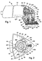
- Fig. 1 in side view and partially Electric hand grinder shown in section is as Orbital sander 9 with a triangular, symmetrical Abrasive plate trained grinding tool 10 designed.
- the Bottom of the sanding plate is made of plastic and is with a Velcro covering 11 for receiving sanding sheets, not shown Mistake.
- the orbital sander 9 has a two-shell machine housing, which is composed of two housing shells 121, 122, those running along a parallel to the longitudinal axis of the housing Butt joint 123.
- a Electric motor 13 added, of which only that on the output shaft 14 seated fan 15 can be seen.
- One on the top of the machine housing 12 arranged on / off switch 16 is used for switching the electric motor on and off 13.
- the output shaft 14 drives a drive shaft 18 via an angular gear 17, the ball bearings 19a and 19b arranged in a housing-fixed manner is rotatably mounted and on the lower end of the machine housing 12 with an eccentric pin 20 from the machine housing 12 projects.
- the inner ring sits axially immovably on the eccentric pin 20 another ball bearing 21, which with its outer ring in held a bowl-shaped tool holder 22, in particular is injected.
- the tool holder made of plastic 22 is attached to the machine housing 12 via a vibrating body 23, so that when the eccentric pin 20 rotates on the Rotational entrainment is prevented and therefore only circular Carries out swinging movement.
- the grinding tool 10 is attached to the tool holder 22 by means of a corresponding one Positive locking elements on the tool holder side or are set on the tool side and by means of a quick lock 24 to be operated manually via an operating button 25 is to be held.
- the grinding tool 10 lies on one Contact surface 37 of the bowl-shaped tool holder 22, which is clearly highlighted by a forward line and includes a dust extraction chamber 26 with the tool holder 22, on the one hand via suction holes 27 in the grinding tool 10 and corresponding, corresponding holes in the sanding sheets to the side to be machined of a workpiece, not shown is open and on the other hand via a bellows 28 with a dust extraction duct running in the machine housing 12 29 is connected, the end of an external suction fan is to be connected.
- Tool-side locking elements 40 are in one piece the grinding tool 10 formed hooks 42 formed on a circular line offset from each other by the same angle of rotation are and of the bearing surface 37 on the tool holder 22 protrude facing the top of the grinding tool 10.
- the Hooks 42 are on the outside for the sake of simplicity Molded sleeve 38, the inner jacket of the polygon profile 39th wearing.
- the interacting holder-side locking elements 41 are formed by an annularly bent spring wire 43 educated.
- a symmetrical polygon profile 36 is formed, which consists of three um same circular arc sections offset from each other by 120 ° 361 consists of three, which are in turn offset by 120 ° to each other, same circular arc sections 362 are connected, the Arc radius is greater than that of the circular arc sections 361.
- the spring wire 43 has one of the number of hooks 42 on the sleeve 38 corresponding number, here three, pointing radially inwards Indentations 431, which in turn correspond to the hook 42 are offset from one another by the same angle of rotation.
- the spring wire 43 is rotatable in the outer slots 51 by webs 44 or slidably received on the tool holder 22, the on an axis 33 of the pin 32 or of the ball bearing 21 Coaxial pitch circle are arranged and in one piece with the tool holder 22 protrude down from this.
- the webs 44 are arranged in pairs so that in the locked position of the spring wire 43, as shown in Fig. 2, each a pair of webs lies on both sides of an indentation 431.
- the web pairs are in turn offset by the same circumferential angle.
- the annularly curved spring wire 43 runs in approximately two radially striving, mutually parallel legs 432 and 433 out.
- One leg 432 is bent at right angles at the end and lies in front of the straight end of leg 433.
- On the free The ends of the legs 432, 433 are the operating button 25 of the quick lock 24 can be clipped on, for which the control button 25 on your Corresponding not shown grooves and locking lugs on the underside having.
- the leg 432 of the spring wire 43 is in this groove is pushed in, with its bent end in a transverse groove comes to rest, while the other leg 433 in one further groove, not shown, is clipped captively.
- the control button 25 can now be used in the transverse slots 51 of the webs 44 guided spring wire 43 in the spring wire plane be pivoted, which in the locked position the hook 42 slip behind recesses 431 away from hook 42, so that the radially outer parts of the Move spring wire 43 to the place of indentations 431 and so that the hook 42 release. Then the grinding tool 10 manually withdrawn from the tool holder 22 in the direction of the axis 33 become. In this position the quick lock 24 can the grinding tool 10 changed and - in the aforementioned training of the grinding tool 10 as a triangular, symmetrical Sanding plate - rotated 120 ° with one corner forward can be inserted again into the tool holder 22.
- the grinding tool 10 can be attached to the tool holder 22 are clipped on.
- the control button 25 can then as well as the rotatable mounting of the spring wire 43 in the transverse slots 51 of the webs 44.
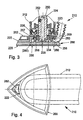
- FIG. 3 shows a section of the front area of the housing 212 of an orbital sander 210 similar to that according to FIGS. 1 and 5 shown.
- the triangular backing pad 268 is with the drive shaft 224 coupled via the tool holder 222.
- a bundle of rings 256 of the tool holder 222 engages around a central outside Ring region 258 of the tool holder 222, which is the first rolling bearing 234 encompasses concentrically.
- the ring collar 256 goes into one short, cross-section-like, radial forehead collar 257 with an outer inclined surface 259.
- the tool holder 222 made of plastic is over a corrugated membrane-like vibrating body 223 attached to the machine housing 212, so that when the eccentric pin 220 rotates on one Rotational entrainment is prevented and thus can only rotate without turning around.
- the top view according to FIG. 4 illustrates the configuration of the Orbital sander 10 as a triangular grinder, its grinding plate 268 easily detachable or lockable by means of the sliding button 262 is.
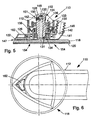
- FIG. 5 essentially shows an enlarged section of a with the orbital sander 9 from Figure 1 or the section 3 corresponding orbital sander 110 and its front area of the housing 112.
- the circular sanding disc shown only in the side section 118 carries a round sanding sheet 120 over an unspecified one Velcro connection.
- Side of the grinding plate 118 closes axially in one Distance to a tool holder 122, which according to FIG triangular sanding plate 268, by means of a sliding button 162
- Detachable, non-rotatable and secured against axial loosening can, but according to Figure 5 only a function as a dust extraction hood Has.
- the tool holder 122 and the grinding plate 118 is one rotatably connected to the motor and in a housing roller bearing 136 rotatably mounted drive shaft 124 coupled.
- the free end the drive shaft 124 is designed as an eccentric pin 126, that of the inner ring 133 of a lower one, with its outer ring 135 in the tool holder 122 pressed in rolling bearing 134 rotatably becomes.
- the rotating drive shaft 124 takes due the free rotatability of the tool holder 122 relative to the Drive shaft 124 only circularly with the tool holder 122 without to be able to turn it.
- the eccentric pin 126 carries one to the axis of the drive shaft 124 central blind bore 128 open on the grinding plate side. In the blind bore 128 engages in a rotationally fixed manner with the grinding plate 118 connected pin 130. Between the grinding plate 118 and there is a positive engagement with the eccentric pin 126 Rotational driving of the grinding plate 118 by a small, axial Driver pin 131 of the grinding plate 118 in an end Recess 132 in the wall of the drive shaft 124 engages.
- the tool holder 122 holds over a corrugated membrane Vibrating element 138 rests or supports elastically on the housing 112 depend on it. Extends into an opening 141 of the tool holder 122 the mouth 142 of a bellows 146, with its the mouth 142 opposite free end in an unillustrated corresponding to the dust removal duct 19 according to FIG. 1 Channel is centered.
- the driver pin 131 engages to take the grinding plate with it 118 parallel to the small, front pin bore 132 to the blind bore 128 of the eccentric pin 126.
- the driving pin 131 is axially parallel at a radial distance from the pin 130 on Sanding disc 118 arranged.
- the assigned to the driver pin 131 Pin bore 132 is parallel to blind bore 128 and Open on the grinding plate side at the free end of the eccentric pin 126 arranged.
- the plug pin 130 carries a circumferential at an upper end Ring groove 148, into which a ball 150 can enter, secured against loss by a spring 152 acts in a radial bore 151 in the wall of the drive shaft 124 sits in the area of the blind bore 128.
- a spring 152 acts in a radial bore 151 in the wall of the drive shaft 124 sits in the area of the blind bore 128.
- Suction openings 154 are identified by dashed lines, which pass through the grinding plate 118 axially and which for Serve dust extraction.
- the grinding dust generated during grinding is through the bellows 146 and the dust removal channel 144 outwards, in particular into a dust bag, promoted.
- FIG. 6 shows the circular contour of the grinding plate 118 and the arrangement of the control button 162 and the angled Course of the machine housing 112 can be seen.
- the orbital sander 109 in the configuration according to FIGS. 5, 6 as a fast rotating Coarse grinding tool in the manner of a flat grinder or disc grinder are used and in the configuration 3, 4 as a rotating triangular grinder without turning for fine or corner grinding.
- a central polygonal pin is provided on the sanding plate, in a suitable, central polygonal bore of the Drive shaft engages.
Landscapes
- Engineering & Computer Science (AREA)
- Mechanical Engineering (AREA)
- Finish Polishing, Edge Sharpening, And Grinding By Specific Grinding Devices (AREA)
Description
Die Erfindung betrifft einen Schwingschleifer nach dem Oberbegriff des Anspruchs 1.The invention relates to an orbital sander according to the preamble of claim 1.
Durch die EP 610 810 ist ein Schwingschleifer bekannt, dessen dreieckiger Schleifteller gemeinsam mit dem dreieckigen Schleifblatt ohne zu rotieren exzentrisch kreisend angetrieben wird. Der Schleifteller dieses Schwingschleifers führt eine kreisende Bewegung aus mit einem exzentrischen Hub von etwa 1,5 mm. Dadurch hat ein einzelnes Schleifkorn eines am Schleifteller befestigten Schleifblatts nur einen geringen Arbeitshub. Infolgedessen ist die Abtrags- bzw. Schleifleistung verhältnismäßig niedrig.From EP 610 810 an orbital sander is known triangular sanding pad together with the triangular sanding sheet is driven eccentrically orbiting without rotating. The grinding disc of this orbital sander has a circular Movement out with an eccentric stroke of about 1.5 mm. Thereby has a single abrasive grain attached to the sanding plate Sanding sheet only a small working stroke. Consequently the removal or grinding performance is proportional low.
Dieser Schwingschleifer ist speziell zum Feinschleifen kleinerer Flächen, besonders in Ecken und an Kanten von Werkstücken konzipiert und nicht zum Grobschliff größerer Flächen, beispielsweise von Holzfußböden geeignet.This orbital sander is specially designed for fine grinding smaller ones Surfaces, especially designed in corners and on the edges of workpieces and not for rough grinding larger areas, for example suitable for wooden floors.
Durch die EP 623 422 ist ein Dreieckschleifer mit einem Schaltgetriebe bekannt, in dessen erster Schaltstufe die Dreh-Schwenk-Bewegung des Schleiftellers, d.h. der Schwingschleiferbetrieb, und in dessen zweiter Schaltstufe die kreisend-rotierende Bewegung des Schleiftellers, d.h. der Exzenterschleiferbetrieb, einstellbar ist.EP 623 422 is a triangular grinder with a manual transmission known, in its first switching stage, the turn-swivel movement of the grinding plate, i.e. the orbital sander operation, and in its second switching stage the circular-rotating movement of the grinding plate, i.e. eccentric sander operation, adjustable is.
Dieser Dreieckschleifer vereint die Eigenschaften eines Drehschwenkschleifers mit denen eines Exzenterschleifers, d.h. damit sind kleinere Flächen effizient fein- und größere Flächen grobschleifbar.This triangular grinder combines the properties of a rotary swivel grinder with those of an eccentric grinder, i.e. in order to smaller surfaces can be finely ground efficiently and larger surfaces can be rough-ground.
Dieser Dreieckschleifer ist aufgrund des eingebauten Schaltgetriebes schwerer und teurer als herkömmliche Schwingschleifer und weniger abtragsstark als bekannte, hochtourig drehende Flachschleifer.This triangular grinder is due to the built-in gearbox heavier and more expensive than conventional orbital sanders and less abrasive than known, high-speed rotating Flat grinder.
Vorteile der ErfindungAdvantages of the invention
Der erfindungsgemäße Schwingschleifer mit den Merkmalen des Anspruchs 1 hat demgegenüber den Vorteil, daß mit geringem Herstellungsaufwand und ohne Veränderung der grundlegenden Konstruktion des Schwingschleifers ein Gerät geschaffen ist, mit dem sowohl der bisherige bekannte Feinschliff insbesondere in Ecken, wobei der eckige Schleifteller kreist ohne sich zu drehen, als auch Grobschliff, wobei der runde Schleifteller hochtourig rotiert, möglich ist. Dabei sind der eckige und der runde Schleifteller besonders einfach und schnell gegeneinander auswechselbar.The orbital sander according to the invention Features of claim 1 has the advantage that with little manufacturing effort and without changing the basic construction of the Orbital sander a device is created with which both Previously known fine-tuning especially in corners, the square grinding disc circles without turning, as well as rough grinding, the round sanding plate rotates at high speed, possible is. The square and round sanding plates are special easily and quickly interchangeable.
Damit ist ein Schwingschleifer geschaffen, der als Flachschleifer mit gegenüber der Abtriebswelle drehfestem und mit dieser zentrisch rotierendem Schleifteller und als Feinschleifer einsetzbar ist und der ebenso handlich wie leichte, aber leistungsschwache Geräte, dafür aber ebenso leistungsfähig wie schwere, dafür aber unhandlichere gewerbliche Flachschleifer ist. This creates an orbital sander, which is a flat grinder with the output shaft against rotation and with this centrically rotating grinding disc and can be used as a fine grinder and is as handy as it is light but underperforming Devices, but as powerful as heavy, but is more unwieldy commercial surface grinder.
Der Schwingschleifer ist dadurch besonders leicht in einen Flachschleifer umrüstbar, daß die Antriebswelle eine zentrische Bohrung trägt, in die ein Zapfen des Schleiftellers drehfest und axial verrastbar, einsetzbar ist.The orbital sander is particularly light in one Surface grinder can be converted so that the drive shaft is centric Bore carries, in which a pin of the grinding plate rotatably and axially lockable, can be used.
Der Schleifteller ist gegenüber der Antriebswelle besonders gegen Verdrehen gesichert durch einen parallel zum Zapfen verlaufenden Mitnehmerzapfen, der formschlüssig in den Exzenterzapfen eingreift und indem die Zapfenbohrung parallel zur Sackbohrung im Exzenterzapfen in einem radialen Abstand zur dieser verläuft.The grinding plate is particularly opposed to the drive shaft Twisted secured by a parallel to the pin Driver pin, the form-fitting in the eccentric pin engages and by the pin hole parallel to the blind hole in the eccentric pin runs at a radial distance from this.
Der Flachschleifteller ist gegen ungewolltes Lösen gesichert, dadurch, daß zwischen dem oberen Bereich des Steckzapfens und der Antriebswelle eine Rastverbindung besteht, wobei eine radial in der Wand der Antriebswelle im Bereich der Sackbohrung verschiebbare, durch eine Feder gestützte Kugel in eine Ringnut des Steckzapfens eingreift.The surface grinding plate is secured against unintentional loosening, characterized in that between the upper region of the plug and the drive shaft has a latching connection, one radial displaceable in the wall of the drive shaft in the area of the blind hole, supported by a spring ball in an annular groove of the Engages.
Die Funktion des Schwingschleifers ohne größere Reibungsverluste als Flachschleifer wird dadurch ermöglicht, daß zwischen dem kreisrunden Schleifteller und dem Werkzeughalter ein axialer Abstand besteht.The function of the orbital sander without major friction losses as a flat grinder is made possible that between the circular grinding plate and the tool holder an axial distance consists.
Der Moduswechsel zwischen der Verwendung als Schwingschleifer oder als Flachschleifer wird dadurch besonders erleichtert, daß der kreisrunde Schleifteller gegen einen eckigen, insbesondere dreieckigen Schleifteller auswechselbar ist, der außer direkter Drehmitnahme mit der Antriebswelle steht und der drehfest, mittels Rastverbindung lösbar mit dem Werkzeughalter koppelbar ist. insbesondere indem die Rastverbindung zwischen dem dreieckigen Schleiferteller und dem Werkzeughalter mittels einer Schiebetaste von Hand arretierbar und lösbar ist.The mode change between use as an orbital sander or as a flat grinder is particularly facilitated in that the circular sanding disc against an angular one, in particular triangular backing pad is interchangeable, which is more direct Rotational entrainment with the drive shaft is and the rotationally fixed, by means of Detent connection can be detachably coupled to the tool holder. especially by the snap connection between the triangular Grinder plate and the tool holder by means of a sliding button can be locked and released by hand.
Da der Schleifteller ein Verschleißteil ist, ist das schnelle Umpositionieren der Eckenbereiche gegenüber dem Werkzeughalter im Schwingschleifermodus bzw. dessen leichte Auswechselbarkeit für den Flachschleifermodus von erheblichem Vorteil. Dieser Vorteil ergibt sich aus dem Zusammenwirken der Rastmittel der Schleifteller mit denen des Werkzeughalters bzw. der Antriebswelle. Damit ist auch der Schleifteller ein wichtiges Bauteil bzw. Ersatzteil. Der Schleifteller hat den Vorteil, daß er zentrisch mit der Antriebswelle drehmitnehmend kuppelbar ist, wobei er einen Steckzapfen und einen Mitnahmezapfen zum Kuppeln mit der Antriebswelle trägt.Since the sanding plate is a wearing part, it is quick Reposition the corner areas in relation to the tool holder in orbital sander mode or its easy interchangeability of considerable advantage for the flat grinder mode. This advantage results from the interaction of the locking means Grinding plate with those of the tool holder or the drive shaft. This is also the sanding plate an important component or spare part. The grinding plate has the advantage that it is centered with the drive shaft is rotatably coupled, with a plug and a driving pin for coupling with the drive shaft wearing.
In der nachfolgenden Beschreibung wird anhand der zugehörigen Zeichnungen die Erfindung näher erläutert.In the following description is based on the associated Drawings the invention explained in more detail.
Es zeigen:
Die in Fig. 1 ausschnittsweise in Seitenansicht und teilweise
geschnitten dargestellte elektrische Handschleifmaschine ist als
Schwingschleifer 9 mit einem als dreieckförmige, symmetrische
Schleifplatte ausgebildeten Schleifwerkzeug 10 ausgestaltet. Die
Unterseite der Schleifplatte besteht aus Kunststoff und ist mit
einem Klettbelag 11 zur Aufnahme nicht dargestellter Schleifblätter
versehen.The detail in Fig. 1 in side view and partially
Electric hand grinder shown in section is as
Der Schwingschleifer 9 besitzt ein zweischaliges Maschinengehäuse,
das aus zwei Gehäuseschalen 121, 122 zusammengesetzt ist,
die längs einer parallel zur Gehäuselängsachse verlaufenden
Trennfuge 123 aneinanderstoßen. Im Maschinengehäuse 12 ist ein
Elektromotor 13 aufgenommen, von dem nur der auf der Abtriebswelle
14 sitzende Lüfter 15 zu sehen ist. Ein auf der Oberseite
des Maschinengehäuses 12 angeordneter Ein-/Ausschalter 16 dient
zum Ein- und Ausschalten des Elektromotors 13. Die Abtriebswelle
14 treibt über ein Winkelgetriebe 17 eine Antriebswelle 18 an,
die in zwei gehäusefest angeordneten Kugellagern 19a und 19b
drehbar gelagert ist und die an der unteren Stirnseite des Maschinengehäuses
12 mit einem Exzenterzapfen 20 aus dem Maschinengehäuse
12 vorsteht.The
Auf dem Exzenterzapfen 20 sitzt axial unverschieblich der Innenring
eines weiteren Kugellagers 21, das mit seinem Außenring in
einem schalenförmigen Werkzeughalter 22 gehalten, insbesondere
eingespritzt, ist. Der aus Kunststoff gefertigte Werkzeughalter
22 ist über einen Schwingkörper 23 am Maschinengehäuse 12 befestigt,
so daß er bei Rotieren des Exzenterzapfens 20 an der
Drehmitnahme gehindert wird und somit eine nur kreisende
Schwingbewegung ausführt.The inner ring sits axially immovably on the
An dem Werkzeughalter 22 ist das Schleifwerkzeug 10 mittels korrespondierender
Formschlußelemente werkzeughalterseitig bzw.
werkzeugseitig festgelegt sind sowie mittels einer Schnellverriegelung
24, die über eine Bedientaste 25 manuell zu betätigen
ist, gehalten werden. Das Schleifwerkzeug 10 liegt dabei auf einer
Auflagefläche 37 des schalenförmigen Werkzeughalters 22 auf,
die durch eine vorgezogene Linie deutlich hervorgehoben ist und
schließt mit dem Werkzeughalter 22 einen Staubabsaugraum 26 ein,
der einerseits über Absauglöcher 27 im Schleifwerkzeug 10 und
entsprechende, korrespondierende Löcher in den Schleifblättern
zu der zu bearbeitenden Seite eines nicht dargestellten Werkstücks
hin offen ist und andererseits über einen Faltenbalg 28
mit einem im Maschinengehäuse 12 verlaufenden Staubabsaugkanal
29 in Verbindung steht, der endseitig an ein Fremd-Sauggebläse
anzuschließen ist.The
Werkzeugseitige Verriegelungselemente 40 sind als einstückig an
das Schleifwerkzeug 10 angeformte Haken 42 ausgebildet, die auf
einer Kreislinie um gleiche Drehwinkel zueinander versetzt angeordnet
sind und von der der Auflagefläche 37 am Werkzeughalter
22 zugekehrten Oberseite des Schleifwerkzeugs 10 abstehen. Die
Haken 42 sind dabei der Einfachheit halber an die Außenseite der
Hülse 38 angeformt, deren Innenmantel das Polygonprofil 39
trägt. Die damit zusammenwirkenden halterseitigen Verriegelungselemente
41 werden von einem ringförmig gebogenen Federdraht 43
gebildet.Tool-side locking elements 40 are in one piece
the
Wie insbesondere aus Fig. 2 ersichtlich ist, ist an der Unterseite
des Werkzeugträgers 22 auf der Außenseite des Zapfens 32
ein symmetrisches Polygonprofil 36 ausgebildet, das aus drei um
jeweils 120° zueinander versetzten, gleichen Kreisbogenabschnitten
361 besteht, die durch drei wiederum um 120° zueinander versetzte,
gleiche Kreisbogenabschnitte 362 verbunden sind, deren
Bogenradius größer ist als der der Kreisbogenabschnitte 361. As can be seen in particular from FIG. 2, is on the underside
of the
Der Federdraht 43 weist eine der Anzahl der Haken 42 an der Hülse
38 entsprechende Zahl, hier drei, von radial nach innen weisenden
Einbuchtungen 431 auf, die entsprechend den Haken 42 wiederum
um gleiche Drehwinkel zueinander versetzt angeordnet sind.
Der Federdraht 43 wird in Ouerschlitzen 51 von Stegen 44 verdrehbar
bzw. verschieblich am Werkzeughalter 22 aufgenommen, die
auf einem zur Achse 33 des Zapfens 32 bzw. des Kugellagers 21
koaxialen Teilkreis angeordnet sind und einstückig mit dem Werkzeughalter
22 von diesem nach unten abstehen. Die Stege 44 sind
paarweise so angeordnet, daß in der Verriegelungslage des Federdrahts
43, wie sie in Fig. 2 dargestellt ist, jeweils ein Stegpaar
beidseitig einer Einbuchtung 431 liegt. Die Stegpaare sind
ihrerseits wiederum um gleiche Umfangswinkel gegeneinander versetzt.
Der ringförmig gebogene Federdraht 43 läuft in zwei etwa
radial wegstrebende, zueinander parallele Schenkel 432 und 433
aus. Der eine Schenkel 432 ist endseitig rechtwinklig abgebogen
und liegt vor dem geraden Ende des Schenkels 433. Auf die freien
Enden der Schenkel 432,433 ist die Bedientaste 25 der Schnellverriegelung
24 aufclipsbar, wozu die Bedientaste 25 auf ihrer
Unterseite entsprechende nichtmitdargestellte Nuten und Rastnasen
aufweist. Der Schenkel 432 des Federdrahts 43 wird dabei in
diese Nut eingedrückt, wobei sein abgebogenes Ende in eine Quernut
zu liegen kommt, während der andere Schenkel 433 in eine
weitere nichtdargestellte Nut unverlierbar eingeclipst wird.The
Mittels der Bedientaste 25 kann nunmehr der in den Querschlitzen
51 der Stege 44 geführte Federdraht 43 in der Federdrahtebene
geschwenkt werden, wodurch die in Verriegelungsstellung die Haken
42 hintergreifenden Einbuchtungen 431 von den Haken 42 weggleiten,
so daß die radial weiter außen befindlichen Teile des
Federdrahts 43 an die Stelle der Einbuchtungen 431 rücken und
damit die Haken 42 freigeben. Daraufhin kann das Schleifwerkzeug
10 in Richtung der Achse 33 vom Werkzeughalter 22 manuell abgezogen
werden. In dieser Stellung der Schnellverriegelung 24 kann
das Schleifwerkzeug 10 gewechselt und - bei der genannten Ausbildung
des Schleifwerkzeugs 10 als dreieckförmige, symmetrische
Schleifplatte - um jeweils 120° gedreht mit einer Ecke nach vorn
wieder in den Werkzeughalter 22 eingesetzt werden. Damit wird
ein gleichmäßiges Abnutzen der Eckbereiche der Schleifblätter
ermöglicht, ohne daß sie dabei vom Klettbelag des Werkzeughalters
22 gelöst werden müssen. Nach Einsetzen des Schleifwerkzeugs
10 durch Ineinanderfügen der beiden Polygonprofile 36, 39
und Auflegen des Schleifwerkzeugs 10 auf die Auflagefläche 37
des Werkzeughalters 22 wird die Bedientaste 25 zurückgeschwenkt
gemäß dem Richtungspfeil 30 in Fig. 2 im Uhrzeigersinn, bis der
Federdraht 43 die in Fig. 2 dargestellte Verriegelungslage einnimmt.
Die Einbuchtungen 431 des Federdrahts 43 hintergreifen
dann wieder die Haken 42 des Schleifwerkzeugs 10, und letzteres
ist am Werkzeughalter 22 fest verriegelt. Bei entsprechender
Ausbildung der werkzeugseitigen Verriegelungselemente 40, z.B.
als federnde Zungen mit den Haken 42 am freien Endes sowie
entsprechend elastischer Ausgestaltung des Federdrahts 43 bzw.
der Einbuchtungen 431 kann das Schleifwerkzeug 10 an den Werkzeughalter
22 angeclipst werden. Die Bedientaste 25 kann dann
ebenso entfallen wie die drehbare Aufnahme des Federdrahts 43 in
den Querschlitzen 51 der Stege 44.The
In Figur 3 ist ein Ausschnitt des vorderen Bereichs des Gehäuses
212 eines Schwingschleifers 210 ähnlich dem gemäß Figur 1 bzw. 5
gezeigt. Der dreieckige Schleifteller 268 ist mit der Antriebswelle
224 über den Werkzeughalter 222 gekoppelt. Ein Ringbund
256 des Werkzeughalters 222 greift außen um einen zentralen
Ringbereich 258 des Werkzeughalters 222, welcher as erste Wälzlager
234 konzentrisch umgreift. Der Ringbund 256 geht in einen
kurzen, im Querschnitt hakenartigen, radialen Stirnbund 257 über
mit einer äußeren Schrägfläche 259.FIG. 3 shows a section of the front area of the
Beim Ansetzen des dreieckigen Schleiftellers 268 an den Werkzeughalter
222 tritt der Ringbund 257 des Schleiftellers 268
durch die radial weiteren Bereiche der mittels Bedientaste verschwenkten
Ringfeder 260, die der Ringfeder 43 gemäß Figur 1 und
2 entspricht, hindurch und hält sich nach Zurückschwenken der
Ringfeder 43 an deren radial engeren Bereichen axial unverschieblich
fest.When attaching the
Der aus Kunststoff gefertigte Werkzeughalter 222 ist über einen
wellmembranartigen Schwingkörper 223 am Maschinengehäuse 212 befestigt,
so daß er bei Rotieren des Exzenterzapfens 220 an einer
Drehmitnahme gehindert wird und somit eine nur kreisen kann ohne
sich dabei zu drehen.The
Die in der Wand der Antriebswelle 224 angeordnete Kugel 250 und
die Feder 252 - ohne wie in Figur 5 einen in der Sackbohrung 228
zu haltenden Zapfen - sind deutlich zu erkennen. Außerdem sind
gestrichelt gezeichnete Absaugöffnungen 266 zum Durchtritt von
abzusaugendem Schleifstaub erkennbar.The
Durch Schwenken einer Schiebetaste 262 wird die Ringfeder 260
mit verschwenkt, so daß sie in gleicher Weise ihre radial weiteren
Bereiche freigibt wie der zu Figur 1 und 2 beschriebene
ringartige Federdraht 43, wobei anschließend der Schleifteller
268 ohne weiteres axial entnommen werden kann.By rotating a
Die Draufsicht gemäß Figur 4 verdeutlicht die Ausgestaltung des
Schwingschleifers 10 als Dreieckschleifer, dessen Schleifteller
268 mittels der Schiebetaste 262 leicht lösbar bzw. arretierbar
ist. The top view according to FIG. 4 illustrates the configuration of the
Figur 5 zeigt als Ausführungsform des Erfindung einen vergrößerten Ausschnitt eines im wesentlichen
mit dem Schwingschleifer 9 aus Figur 1 bzw. dem Ausschnitt
gemäß Figur 3 übereinstimmenden Schwingschleifer 110 sowie dessen
vorderen Bereich des Gehäuses 112.As an embodiment of the invention, FIG. 5 essentially shows an enlarged section of a
with the
Der kreisrunde, nur im seitlichen Schnitt gezeigte Schleifteller
118 trägt ein rundes Schleifblatt 120 über eine nicht näher bezeichnete
Klettverbindung. Auf der dem Schleifblatt 120 abgewandten
Seite des Schleiftellers 118 schließt sich axial in einem
Abstand ein Werkzeughalter 122 an, der gemäß Figur 3 den
dreieckigen Schleiftellers 268, mittels einer Schiebetaste 162
lösbar, drehfest und gegen axiales Lösen gesichert aufnehmen
kann, der aber gemäß Figur 5 nur eine Funktion als Staub-Absaughaube
hat.The circular sanding disc shown only in the
Mit dem Werkzeughalter 122 und dem Schleifteller 118 ist eine
mit dem Motor drehverbundene und in einem Gehäusewälzlager 136
drehbar gelagerte Antriebswelle 124 gekoppelt. Das freie Ende
der Antriebswelle 124 ist als Exzenterzapfen 126 ausgestaltet,
der vom Innering 133 eines unteren, mit seinem Außenring 135 in
den Werkzeughalter 122 eingepreßten Wälzlagers 134 drehfest umgriffen
wird. Die sich drehende Antriebswelle 124 nimmt aufgrund
der freien Verdrehbarkeit des Werkzeughalter 122 gegenüber der
Antriebswelle 124 den Werkzeughalter 122 nur kreisend mit ohne
ihn drehen zu können.With the
Der Exzenterzapfen 126 trägt eine zur Achse der Antriebswelle
124 zentrische, schleiftellerseitig offene Sackbohrung 128. In
die Sackbohrung 128 greift ein drehfest mit dem Schleifteller
118 verbundener Zapfen 130. Zwischen dem Schleifteller 118 und
dem Exzenterzapfen 126 besteht ein formschlüssiger Eingriff zur
Drehmitnahme des Schleiftellers 118, indem ein kleiner, axialer
Mitnehmerzapfen 131 des Schleiftellers 118 in eine stirnseitige
Ausnehmung 132 in der Wand der Antriebswelle 124 greift. The eccentric pin 126 carries one to the axis of the
Der Werkzeughalter 122 hält sich über ein wellmembranartiges
Schwingelement 138 elastisch am Gehäuse 112 fest bzw. stützt
sich daran ab. In eine Öffnung 141 des Werkzeughalters 122 ragt
die Mündung 142 eines Faltenbalgs 146, der mit seinem der Mündung
142 gegenüberliegenden freien Ende in einem nichtmitdargestellten
dem Staubabtransportkanal 19 gemäß Figur 1 entsprechenden
Kanal zentriert ist.The
Der Mitnehmerzapfen 131 greift zur Drehmitnahme des Schleiftellers
118 in die kleine, stirnseitige Zapfenbohrung 132 parallel
zur Sackbohrung 128 des Exzenterzapfens 126. Der Mitnehmerzapfen
131 ist achsparallel in einem radialen Abstand zum Zapfen 130 am
Schleifteller 118 angeordnet. Die dem Mitnehmerzapfen 131 zugeordnete
Zapfenbohrung 132 ist parallel zur Sackbohrung 128 und
schleiftellerseitig offen am freien Ende des Exzenterzapfens 126
angeordnet.The
Zwischen dem Schleifteller 118 und dem Werkzeughalter 122 ist
ein axialer Abstand in Gestalt einer Fuge 147 erkennbar, die so
groß ist, daß sie auch bei axialem Druck auf den Schleifteller
118 beim Arbeiten mit dem Schwingschleifer 110 nur unwesentlich
verringert wird. Dadurch kommt der Schleifteller 118 am Werkzeughalter
122 nicht zur Anlage, so daß der Schleifteller 118
sich reibungsfrei gegenüber der Werkzeughalter 122 drehen kann
und daß somit der Schwingschleifer 110 als Tellerschleifer mit
ausschließlich zentrisch drehender, insbesondere hochtouriger
Bewegung des Schleiftellers 118 arbeitet.Is between the grinding
Der Steckzapfen 130 trägt an einem oberen Ende eine umlaufende
Ringnut 148, in die überrastend eine Kugel 150 eintreten kann,
die gegen Verlieren gesichert verschiebar von einer Feder 152
beaufschlagt in einer radialen Bohrung 151 in der Wand der Antriebswelle
124 im Bereich der Sackbohrung 128 sitzt. Mit der
federbeaufschlagten Kugel 150 und der Ringnut 148 ist eine Überrastverbindung
zwischen dem Steckzapfen 130 und der Antriebswelle
124 geschaffen, die ein ungewolltes axiales Lösen des
Schleiftellers 118 mit seinem Zapfen 130 aus der Sackbohrung 128
verhindert, so daß der Schleifteller 118 gegen ungewolltes Verlieren
gesichert am Schwingschleifer 110 befestigt ist. Durch
axiales Abziehen des Schleiftellers nur durch die Hand des Bedienenden
kann der Werkzeug- und Verwendungwechsel sehr leicht,
ohne Hilfswerkzeug erfolgen.The
Durch gestrichelte Linien sind Absaugöffnungen 154 gekennzeichnet,
die den Schleifteller 118 axial durchtreten und die zur
Staubabsaugung dienen. Der beim Schleifen anfallende Schleifstaub
wird durch den Faltenbalg 146 und den Staubabtransportkanal
144 hindurch nach außen, insbesondere in einen Staubsack,
gefördert.
In Figur 6 ist die kreisförmige Kontur des Schleiftellers 118
und die Anordnung der Bedientaste 162 sowie der abgewinkelte
Verlauf des Maschinengehäuses 112 erkennbar.6 shows the circular contour of the grinding
Infolge der Auswechselbarkeit des kreisrunden Schleiftellers 118
gemäß Figur 5 und 6 gegen den dreieckigen Schleifteller 268 gemäß
Figur 3 und 4 in der beschriebenen Weise kann der Schwingschleifer
109 in der Konfiguration gemäß Figur 5, 6 als schnelldrehendes
Grobschleifwerkzeug in der Art eines Flachschleifers
bzw. Tellerschleifers verwendet werden und in der Konfiguration
gemäß Figur 3, 4 als kreisend ohne Drehen bewegter Dreieckschleifer
zum Fein- bzw. zum Eckenschleifen.As a result of the interchangeability of the
Bei einem nicht dargestellten Ausführungsbeispiel des formschlüssigen Eingriffs zwischen dem Schleifteller und dem Exzenterzapfen ist anstelle eines Mitnehmerzapfens und einer Zapfenbohrung ein zentrischer Mehrkantzapfen am Schleifteller vorgesehen, der in eine passende, zentrische Mehrkantbohrung der Antriebswelle greift.In a not shown embodiment of the positive Engagement between the grinding plate and the eccentric pin is instead of a driver pin and a pin hole a central polygonal pin is provided on the sanding plate, in a suitable, central polygonal bore of the Drive shaft engages.
Claims (8)
- Vibratory sander (9, 110, 210) having a housing (12, 112, 212), in which a drive shaft (18, 124, 224) is rotatably mounted such that it can be driven by means of a motor, which drive shaft, by means of an eccentric pin (20, 126, 226), imparts an orbital motion to a sanding plate (10, 118, 268), which is coupled elastically movably to the housing (12, 112, 212) via at least one vibrating element (23, 138, 238) attached to the housing, characterized in that, instead of the orbitally vibrating sanding plate (10, 118, 268), a sanding plate (118), preferably a circular sanding plate (118), which rotates together with the drive shaft (18, 124, 224) is fastened centrically and in a rotationally fixed manner on the said drive shaft, in particular on the eccentric pin (20, 126, 226), in an exchangeable manner.
- Vibratory sander according to Claim 1, characterized in that the eccentric pin (20, 126, 226) bears a bore (128) which is centric with respect to the drive shaft (18, 124, 224) and into which a pin (130) of the sanding plate (118) can be inserted in a rotationally fixed, in particular axially latchable, manner.
- Vibratory sander according to Claim 1 or 2,
characterized in that the sanding plate (118) bears a driver, in particular a driver pin (131), which runs parallel to the pin (130) and engages in a positively locking manner in the eccentric pin (126), in particular in a driver bore (132) which is open at the end. - Vibratory sander according to Claim 3, characterized in that the driver bore (132) runs parallel to the bore (128, 228) in the eccentric pin (126), at a radial distance from the said bore.
- Vibratory sander according to Claim 4, characterized in that there is a latching connection between the upper region of the plug-in pin (130) and the drive shaft (124), a ball (150), which can be displaced radially in the wall of the drive shaft (124) in the region of the centric bore (128) and is supported by a spring (152), engaging in an annular groove (148) of the plug-in pin (130).
- Vibratory sander according to one of the preceding claims, characterized in that there is an axial distance (147) between the circular sanding plate (118) and the tool holder (122).
- Vibratory sander according to one of the preceding claims, characterized in that the sanding plate (118) can be exchanged for a polygonal, in particular triangular, sanding plate (268), which can be coupled to the tool holder in a rotationally fixed, releasable manner (122, 222) by means of a latching connection.
- Vibratory sander according to Claim 7, characterized in that the latching connection between the triangular sanding plate (168) and the tool holder (122) can be locked and released manually by means of a sliding button (162).
Applications Claiming Priority (3)
| Application Number | Priority Date | Filing Date | Title |
|---|---|---|---|
| DE19617474 | 1996-05-02 | ||
| DE19617474A DE19617474A1 (en) | 1996-05-02 | 1996-05-02 | Orbital sander |
| PCT/DE1997/000139 WO1997042000A1 (en) | 1996-05-02 | 1997-01-28 | Orbital sander |
Publications (2)
| Publication Number | Publication Date |
|---|---|
| EP0842012A1 EP0842012A1 (en) | 1998-05-20 |
| EP0842012B1 true EP0842012B1 (en) | 2002-04-17 |
Family
ID=7793012
Family Applications (1)
| Application Number | Title | Priority Date | Filing Date |
|---|---|---|---|
| EP97907018A Expired - Lifetime EP0842012B1 (en) | 1996-05-02 | 1997-01-28 | Orbital sander |
Country Status (5)
| Country | Link |
|---|---|
| EP (1) | EP0842012B1 (en) |
| JP (1) | JPH11508831A (en) |
| CN (1) | CN1115232C (en) |
| DE (2) | DE19617474A1 (en) |
| WO (1) | WO1997042000A1 (en) |
Families Citing this family (8)
| Publication number | Priority date | Publication date | Assignee | Title |
|---|---|---|---|---|
| DE102006060652B4 (en) | 2006-12-21 | 2019-09-05 | Robert Bosch Gmbh | Chisel or chisel hammer with a bellows |
| US7736216B2 (en) | 2008-08-20 | 2010-06-15 | Black & Decker Inc. | Sander having removable platen |
| DE102011084591A1 (en) * | 2011-10-17 | 2013-04-18 | Robert Bosch Gmbh | Machine tools fixture |
| DE102012210893B4 (en) * | 2012-06-26 | 2026-02-19 | Robert Bosch Gmbh | Hand grinder with a vibrating plate |
| CN107756202B (en) * | 2016-08-15 | 2023-12-08 | 苏州宝时得电动工具有限公司 | Sanding machine |
| CN107791130B (en) * | 2016-09-07 | 2023-12-08 | 苏州宝时得电动工具有限公司 | Multifunctional sander |
| US20200338686A1 (en) * | 2017-08-04 | 2020-10-29 | Positec Power Tools (Suzhou) Co., Ltd. | Grinding tool, and main component and grinding component thereof |
| US10603760B2 (en) | 2017-09-19 | 2020-03-31 | Campbell Hausfeld, Llc | Multifunction rotary tool including hub |
Family Cites Families (3)
| Publication number | Priority date | Publication date | Assignee | Title |
|---|---|---|---|---|
| DE3935179A1 (en) * | 1989-10-23 | 1991-04-25 | Werkzeug Gmbh | ATTACHMENT FOR AN ANGLE GRINDER |
| DE4314799C2 (en) * | 1993-05-05 | 1995-04-13 | Fein C & E | Power tool |
| US5482499A (en) * | 1993-11-18 | 1996-01-09 | Ryobi Limited | Sanding apparatus |
-
1996
- 1996-05-02 DE DE19617474A patent/DE19617474A1/en not_active Withdrawn
-
1997
- 1997-01-28 DE DE59707033T patent/DE59707033D1/en not_active Expired - Fee Related
- 1997-01-28 EP EP97907018A patent/EP0842012B1/en not_active Expired - Lifetime
- 1997-01-28 JP JP9539395A patent/JPH11508831A/en active Pending
- 1997-01-28 CN CN97190476A patent/CN1115232C/en not_active Expired - Fee Related
- 1997-01-28 WO PCT/DE1997/000139 patent/WO1997042000A1/en not_active Ceased
Also Published As
| Publication number | Publication date |
|---|---|
| WO1997042000A1 (en) | 1997-11-13 |
| EP0842012A1 (en) | 1998-05-20 |
| CN1190364A (en) | 1998-08-12 |
| CN1115232C (en) | 2003-07-23 |
| JPH11508831A (en) | 1999-08-03 |
| DE19617474A1 (en) | 1997-11-06 |
| DE59707033D1 (en) | 2002-05-23 |
Similar Documents
| Publication | Publication Date | Title |
|---|---|---|
| EP0836544B1 (en) | Electric hand-operated grinder | |
| EP0916456B1 (en) | Electric hand tool | |
| EP0868264B1 (en) | Electric hand tool | |
| DE202010008240U1 (en) | Multifunction power tool | |
| EP0820838B1 (en) | Sander with eccentrically driven tool | |
| EP2366494B1 (en) | Manually operated machine tool with a forced rotation eccentric drive | |
| DE102010031329A1 (en) | Tool holder for a machine tool | |
| EP0842012B1 (en) | Orbital sander | |
| EP1795301B1 (en) | Grinding disc with quick mount-and-release mechanism and disc grinder with such a grinding disc | |
| WO1998006539A1 (en) | Vibrating grinder | |
| EP0842011B1 (en) | Orbital sander | |
| DE4102482A1 (en) | HAND MACHINE TOOL | |
| EP1377412A1 (en) | Connecting sleeve for connecting a suction hose to a hand machine tool | |
| DE4238245A1 (en) | Hand-held power driven polishing or grinding tool - has attached duct which can be connected to suction source to remove dust generated by tool | |
| EP2366495B1 (en) | Manually operated machine tool with an eccentric drive and a latch | |
| DE4432974B4 (en) | Hand-guided, electric belt sander | |
| EP3812100A1 (en) | Electric hand-held machine tool | |
| EP0730931B1 (en) | Mechanised tool for grinding, rasping, filing or polishing | |
| DE8914346U1 (en) | Tool that can be driven by a motor to produce a rotary movement | |
| EP3934847B1 (en) | System comprising a dust hood extension device and an adapter | |
| DE10132885B4 (en) | hand grinder | |
| DE102013212484B4 (en) | Hand machine tools, in particular roller grinders | |
| DE102004055270A1 (en) | guiding device | |
| DE10003504A1 (en) | Manual grinding apparatus has motorized movable support element to carry working head to which grinding device can be fastened | |
| DE1652099A1 (en) | Portable machine tool for surface machining |
Legal Events
| Date | Code | Title | Description |
|---|---|---|---|
| PUAI | Public reference made under article 153(3) epc to a published international application that has entered the european phase |
Free format text: ORIGINAL CODE: 0009012 |
|
| AK | Designated contracting states |
Kind code of ref document: A1 Designated state(s): DE GB IT |
|
| 17P | Request for examination filed |
Effective date: 19980513 |
|
| 17Q | First examination report despatched |
Effective date: 20000328 |
|
| GRAG | Despatch of communication of intention to grant |
Free format text: ORIGINAL CODE: EPIDOS AGRA |
|
| GRAG | Despatch of communication of intention to grant |
Free format text: ORIGINAL CODE: EPIDOS AGRA |
|
| GRAH | Despatch of communication of intention to grant a patent |
Free format text: ORIGINAL CODE: EPIDOS IGRA |
|
| GRAH | Despatch of communication of intention to grant a patent |
Free format text: ORIGINAL CODE: EPIDOS IGRA |
|
| REG | Reference to a national code |
Ref country code: GB Ref legal event code: IF02 |
|
| GRAA | (expected) grant |
Free format text: ORIGINAL CODE: 0009210 |
|
| AK | Designated contracting states |
Kind code of ref document: B1 Designated state(s): DE GB IT |
|
| REF | Corresponds to: |
Ref document number: 59707033 Country of ref document: DE Date of ref document: 20020523 |
|
| GBT | Gb: translation of ep patent filed (gb section 77(6)(a)/1977) |
Effective date: 20020709 |
|
| PLBE | No opposition filed within time limit |
Free format text: ORIGINAL CODE: 0009261 |
|
| STAA | Information on the status of an ep patent application or granted ep patent |
Free format text: STATUS: NO OPPOSITION FILED WITHIN TIME LIMIT |
|
| 26N | No opposition filed |
Effective date: 20030120 |
|
| PG25 | Lapsed in a contracting state [announced via postgrant information from national office to epo] |
Ref country code: IT Free format text: LAPSE BECAUSE OF NON-PAYMENT OF DUE FEES;WARNING: LAPSES OF ITALIAN PATENTS WITH EFFECTIVE DATE BEFORE 2007 MAY HAVE OCCURRED AT ANY TIME BEFORE 2007. THE CORRECT EFFECTIVE DATE MAY BE DIFFERENT FROM THE ONE RECORDED. Effective date: 20050128 |
|
| PGFP | Annual fee paid to national office [announced via postgrant information from national office to epo] |
Ref country code: GB Payment date: 20090123 Year of fee payment: 13 |
|
| PGFP | Annual fee paid to national office [announced via postgrant information from national office to epo] |
Ref country code: DE Payment date: 20090327 Year of fee payment: 13 |
|
| GBPC | Gb: european patent ceased through non-payment of renewal fee |
Effective date: 20100128 |
|
| PG25 | Lapsed in a contracting state [announced via postgrant information from national office to epo] |
Ref country code: DE Free format text: LAPSE BECAUSE OF NON-PAYMENT OF DUE FEES Effective date: 20100803 |
|
| PG25 | Lapsed in a contracting state [announced via postgrant information from national office to epo] |
Ref country code: GB Free format text: LAPSE BECAUSE OF NON-PAYMENT OF DUE FEES Effective date: 20100128 |