EP0842012B1 - Ponceuse vibrante - Google Patents
Ponceuse vibrante Download PDFInfo
- Publication number
- EP0842012B1 EP0842012B1 EP97907018A EP97907018A EP0842012B1 EP 0842012 B1 EP0842012 B1 EP 0842012B1 EP 97907018 A EP97907018 A EP 97907018A EP 97907018 A EP97907018 A EP 97907018A EP 0842012 B1 EP0842012 B1 EP 0842012B1
- Authority
- EP
- European Patent Office
- Prior art keywords
- pin
- drive shaft
- sanding plate
- tool holder
- bore
- Prior art date
- Legal status (The legal status is an assumption and is not a legal conclusion. Google has not performed a legal analysis and makes no representation as to the accuracy of the status listed.)
- Expired - Lifetime
Links
Images
Classifications
-
- B—PERFORMING OPERATIONS; TRANSPORTING
- B24—GRINDING; POLISHING
- B24B—MACHINES, DEVICES, OR PROCESSES FOR GRINDING OR POLISHING; DRESSING OR CONDITIONING OF ABRADING SURFACES; FEEDING OF GRINDING, POLISHING, OR LAPPING AGENTS
- B24B23/00—Portable grinding machines, e.g. hand-guided; Accessories therefor
- B24B23/04—Portable grinding machines, e.g. hand-guided; Accessories therefor with oscillating grinding tools; Accessories therefor
-
- B—PERFORMING OPERATIONS; TRANSPORTING
- B24—GRINDING; POLISHING
- B24B—MACHINES, DEVICES, OR PROCESSES FOR GRINDING OR POLISHING; DRESSING OR CONDITIONING OF ABRADING SURFACES; FEEDING OF GRINDING, POLISHING, OR LAPPING AGENTS
- B24B23/00—Portable grinding machines, e.g. hand-guided; Accessories therefor
- B24B23/02—Portable grinding machines, e.g. hand-guided; Accessories therefor with rotating grinding tools; Accessories therefor
Definitions
- the invention relates to an orbital sander according to the preamble of claim 1.
- an orbital sander is known triangular sanding pad together with the triangular sanding sheet is driven eccentrically orbiting without rotating.
- the grinding disc of this orbital sander has a circular Movement out with an eccentric stroke of about 1.5 mm. Thereby has a single abrasive grain attached to the sanding plate Sanding sheet only a small working stroke. Consequently the removal or grinding performance is proportional low.
- This orbital sander is specially designed for fine grinding smaller ones Surfaces, especially designed in corners and on the edges of workpieces and not for rough grinding larger areas, for example suitable for wooden floors.
- EP 623 422 is a triangular grinder with a manual transmission known, in its first switching stage, the turn-swivel movement of the grinding plate, i.e. the orbital sander operation, and in its second switching stage the circular-rotating movement of the grinding plate, i.e. eccentric sander operation, adjustable is.
- This triangular grinder combines the properties of a rotary swivel grinder with those of an eccentric grinder, i.e. in order to smaller surfaces can be finely ground efficiently and larger surfaces can be rough-ground.
- This triangular grinder is due to the built-in gearbox heavier and more expensive than conventional orbital sanders and less abrasive than known, high-speed rotating Flat grinder.
- the orbital sander according to the invention has the advantage that with little manufacturing effort and without changing the basic construction of the Orbital sander a device is created with which both Previously known fine-tuning especially in corners, the square grinding disc circles without turning, as well as rough grinding, the round sanding plate rotates at high speed, possible is.
- the square and round sanding plates are special easily and quickly interchangeable.
- This creates an orbital sander which is a flat grinder with the output shaft against rotation and with this centrically rotating grinding disc and can be used as a fine grinder and is as handy as it is light but underperforming Devices, but as powerful as heavy, but is more unwieldy commercial surface grinder.
- the orbital sander is particularly light in one Surface grinder can be converted so that the drive shaft is centric Bore carries, in which a pin of the grinding plate rotatably and axially lockable, can be used.
- the grinding plate is particularly opposed to the drive shaft Twisted secured by a parallel to the pin Driver pin, the form-fitting in the eccentric pin engages and by the pin hole parallel to the blind hole in the eccentric pin runs at a radial distance from this.
- the surface grinding plate is secured against unintentional loosening, characterized in that between the upper region of the plug and the drive shaft has a latching connection, one radial displaceable in the wall of the drive shaft in the area of the blind hole, supported by a spring ball in an annular groove of the Engages.
- the mode change between use as an orbital sander or as a flat grinder is particularly facilitated in that the circular sanding disc against an angular one, in particular triangular backing pad is interchangeable, which is more direct Rotational entrainment with the drive shaft is and the rotationally fixed, by means of Detent connection can be detachably coupled to the tool holder. especially by the snap connection between the triangular Grinder plate and the tool holder by means of a sliding button can be locked and released by hand.
- the sanding plate Since the sanding plate is a wearing part, it is quick Reposition the corner areas in relation to the tool holder in orbital sander mode or its easy interchangeability of considerable advantage for the flat grinder mode. This advantage results from the interaction of the locking means Grinding plate with those of the tool holder or the drive shaft. This is also the sanding plate an important component or spare part.
- the grinding plate has the advantage that it is centered with the drive shaft is rotatably coupled, with a plug and a driving pin for coupling with the drive shaft wearing.
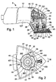
- Fig. 1 in side view and partially Electric hand grinder shown in section is as Orbital sander 9 with a triangular, symmetrical Abrasive plate trained grinding tool 10 designed.
- the Bottom of the sanding plate is made of plastic and is with a Velcro covering 11 for receiving sanding sheets, not shown Mistake.
- the orbital sander 9 has a two-shell machine housing, which is composed of two housing shells 121, 122, those running along a parallel to the longitudinal axis of the housing Butt joint 123.
- a Electric motor 13 added, of which only that on the output shaft 14 seated fan 15 can be seen.
- One on the top of the machine housing 12 arranged on / off switch 16 is used for switching the electric motor on and off 13.
- the output shaft 14 drives a drive shaft 18 via an angular gear 17, the ball bearings 19a and 19b arranged in a housing-fixed manner is rotatably mounted and on the lower end of the machine housing 12 with an eccentric pin 20 from the machine housing 12 projects.
- the inner ring sits axially immovably on the eccentric pin 20 another ball bearing 21, which with its outer ring in held a bowl-shaped tool holder 22, in particular is injected.
- the tool holder made of plastic 22 is attached to the machine housing 12 via a vibrating body 23, so that when the eccentric pin 20 rotates on the Rotational entrainment is prevented and therefore only circular Carries out swinging movement.
- the grinding tool 10 is attached to the tool holder 22 by means of a corresponding one Positive locking elements on the tool holder side or are set on the tool side and by means of a quick lock 24 to be operated manually via an operating button 25 is to be held.
- the grinding tool 10 lies on one Contact surface 37 of the bowl-shaped tool holder 22, which is clearly highlighted by a forward line and includes a dust extraction chamber 26 with the tool holder 22, on the one hand via suction holes 27 in the grinding tool 10 and corresponding, corresponding holes in the sanding sheets to the side to be machined of a workpiece, not shown is open and on the other hand via a bellows 28 with a dust extraction duct running in the machine housing 12 29 is connected, the end of an external suction fan is to be connected.
- Tool-side locking elements 40 are in one piece the grinding tool 10 formed hooks 42 formed on a circular line offset from each other by the same angle of rotation are and of the bearing surface 37 on the tool holder 22 protrude facing the top of the grinding tool 10.
- the Hooks 42 are on the outside for the sake of simplicity Molded sleeve 38, the inner jacket of the polygon profile 39th wearing.
- the interacting holder-side locking elements 41 are formed by an annularly bent spring wire 43 educated.
- a symmetrical polygon profile 36 is formed, which consists of three um same circular arc sections offset from each other by 120 ° 361 consists of three, which are in turn offset by 120 ° to each other, same circular arc sections 362 are connected, the Arc radius is greater than that of the circular arc sections 361.
- the spring wire 43 has one of the number of hooks 42 on the sleeve 38 corresponding number, here three, pointing radially inwards Indentations 431, which in turn correspond to the hook 42 are offset from one another by the same angle of rotation.
- the spring wire 43 is rotatable in the outer slots 51 by webs 44 or slidably received on the tool holder 22, the on an axis 33 of the pin 32 or of the ball bearing 21 Coaxial pitch circle are arranged and in one piece with the tool holder 22 protrude down from this.
- the webs 44 are arranged in pairs so that in the locked position of the spring wire 43, as shown in Fig. 2, each a pair of webs lies on both sides of an indentation 431.
- the web pairs are in turn offset by the same circumferential angle.
- the annularly curved spring wire 43 runs in approximately two radially striving, mutually parallel legs 432 and 433 out.
- One leg 432 is bent at right angles at the end and lies in front of the straight end of leg 433.
- On the free The ends of the legs 432, 433 are the operating button 25 of the quick lock 24 can be clipped on, for which the control button 25 on your Corresponding not shown grooves and locking lugs on the underside having.
- the leg 432 of the spring wire 43 is in this groove is pushed in, with its bent end in a transverse groove comes to rest, while the other leg 433 in one further groove, not shown, is clipped captively.
- the control button 25 can now be used in the transverse slots 51 of the webs 44 guided spring wire 43 in the spring wire plane be pivoted, which in the locked position the hook 42 slip behind recesses 431 away from hook 42, so that the radially outer parts of the Move spring wire 43 to the place of indentations 431 and so that the hook 42 release. Then the grinding tool 10 manually withdrawn from the tool holder 22 in the direction of the axis 33 become. In this position the quick lock 24 can the grinding tool 10 changed and - in the aforementioned training of the grinding tool 10 as a triangular, symmetrical Sanding plate - rotated 120 ° with one corner forward can be inserted again into the tool holder 22.
- the grinding tool 10 can be attached to the tool holder 22 are clipped on.
- the control button 25 can then as well as the rotatable mounting of the spring wire 43 in the transverse slots 51 of the webs 44.
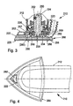
- FIG. 3 shows a section of the front area of the housing 212 of an orbital sander 210 similar to that according to FIGS. 1 and 5 shown.
- the triangular backing pad 268 is with the drive shaft 224 coupled via the tool holder 222.
- a bundle of rings 256 of the tool holder 222 engages around a central outside Ring region 258 of the tool holder 222, which is the first rolling bearing 234 encompasses concentrically.
- the ring collar 256 goes into one short, cross-section-like, radial forehead collar 257 with an outer inclined surface 259.
- the tool holder 222 made of plastic is over a corrugated membrane-like vibrating body 223 attached to the machine housing 212, so that when the eccentric pin 220 rotates on one Rotational entrainment is prevented and thus can only rotate without turning around.
- the top view according to FIG. 4 illustrates the configuration of the Orbital sander 10 as a triangular grinder, its grinding plate 268 easily detachable or lockable by means of the sliding button 262 is.
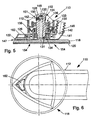
- FIG. 5 essentially shows an enlarged section of a with the orbital sander 9 from Figure 1 or the section 3 corresponding orbital sander 110 and its front area of the housing 112.
- the circular sanding disc shown only in the side section 118 carries a round sanding sheet 120 over an unspecified one Velcro connection.
- Side of the grinding plate 118 closes axially in one Distance to a tool holder 122, which according to FIG triangular sanding plate 268, by means of a sliding button 162
- Detachable, non-rotatable and secured against axial loosening can, but according to Figure 5 only a function as a dust extraction hood Has.
- the tool holder 122 and the grinding plate 118 is one rotatably connected to the motor and in a housing roller bearing 136 rotatably mounted drive shaft 124 coupled.
- the free end the drive shaft 124 is designed as an eccentric pin 126, that of the inner ring 133 of a lower one, with its outer ring 135 in the tool holder 122 pressed in rolling bearing 134 rotatably becomes.
- the rotating drive shaft 124 takes due the free rotatability of the tool holder 122 relative to the Drive shaft 124 only circularly with the tool holder 122 without to be able to turn it.
- the eccentric pin 126 carries one to the axis of the drive shaft 124 central blind bore 128 open on the grinding plate side. In the blind bore 128 engages in a rotationally fixed manner with the grinding plate 118 connected pin 130. Between the grinding plate 118 and there is a positive engagement with the eccentric pin 126 Rotational driving of the grinding plate 118 by a small, axial Driver pin 131 of the grinding plate 118 in an end Recess 132 in the wall of the drive shaft 124 engages.
- the tool holder 122 holds over a corrugated membrane Vibrating element 138 rests or supports elastically on the housing 112 depend on it. Extends into an opening 141 of the tool holder 122 the mouth 142 of a bellows 146, with its the mouth 142 opposite free end in an unillustrated corresponding to the dust removal duct 19 according to FIG. 1 Channel is centered.
- the driver pin 131 engages to take the grinding plate with it 118 parallel to the small, front pin bore 132 to the blind bore 128 of the eccentric pin 126.
- the driving pin 131 is axially parallel at a radial distance from the pin 130 on Sanding disc 118 arranged.
- the assigned to the driver pin 131 Pin bore 132 is parallel to blind bore 128 and Open on the grinding plate side at the free end of the eccentric pin 126 arranged.
- the plug pin 130 carries a circumferential at an upper end Ring groove 148, into which a ball 150 can enter, secured against loss by a spring 152 acts in a radial bore 151 in the wall of the drive shaft 124 sits in the area of the blind bore 128.
- a spring 152 acts in a radial bore 151 in the wall of the drive shaft 124 sits in the area of the blind bore 128.
- Suction openings 154 are identified by dashed lines, which pass through the grinding plate 118 axially and which for Serve dust extraction.
- the grinding dust generated during grinding is through the bellows 146 and the dust removal channel 144 outwards, in particular into a dust bag, promoted.
- FIG. 6 shows the circular contour of the grinding plate 118 and the arrangement of the control button 162 and the angled Course of the machine housing 112 can be seen.
- the orbital sander 109 in the configuration according to FIGS. 5, 6 as a fast rotating Coarse grinding tool in the manner of a flat grinder or disc grinder are used and in the configuration 3, 4 as a rotating triangular grinder without turning for fine or corner grinding.
- a central polygonal pin is provided on the sanding plate, in a suitable, central polygonal bore of the Drive shaft engages.
Landscapes
- Engineering & Computer Science (AREA)
- Mechanical Engineering (AREA)
- Finish Polishing, Edge Sharpening, And Grinding By Specific Grinding Devices (AREA)
Claims (8)
- Ponceuse vibrante (9, 110, 210) comportant un boítier (12, 112, 212) dans lequel est monté à rotation, un arbre d'entraínement (18, 124, 224) entraíné par un moteur, cet arbre communiquant un mouvement orbital par l'intermédiaire d'un tourillon excentrique (20, 126, 226) à un plateau de ponçage (10, 118, 268) couplé de manière mobile élastiquement avec le boítier (12, 112, 212) par au moins un élément oscillant (23, 138, 238) porté par le boítier,
caractérisée en ce qu'
à la place du plateau de ponçage (10, 118, 268) oscillant suivant un mouvement orbital, un plateau de ponçage (118), tournant en commun avec l'arbre d'entraínement (18, 124, 224), de préférence circulaire, est fixé de manière interchangeable centrée solidairement en rotation à l'arbre, notamment au tourillon excentrique (20, 126, 226). - Ponceuse vibrante selon la revendication 1,
caractérisée en ce que
le tourillon excentrique (20, 126, 226) présente un perçage central (128) par rapport à l'arbre d'entraínement (18; 124, 224) dans lequel se place un tourillon (130) du plateau de ponçage (118), de manière solidaire en rotation, notamment bloqué axialement. - Ponceuse vibrante selon la revendication 1 ou 2,
caractérisée en ce que
le plateau de ponçage (118) porte un organe d'entraínement, notamment un téton d'entraínement (131), parallèle au tourillon (130) qui pénètre par une liaison de forme dans le tourillon excentrique (126), notamment dans un perçage d'entraínement (132) ouvert dans la face frontale. - Ponceuse vibrante selon la revendication 3,
caractérisée en ce que
le perçage d'entraínement (132) est parallèle au perçage (128, 228) dans le tourillon excentrique (126), à une distance radiale de celui-ci. - Ponceuse vibrante selon la revendication 4,
caractérisée en ce qu'
entre la zone supérieure du tourillon enfichable (130) et l'arbre d'entraínement (124) il est prévu une liaison par encliquetage et une bille (150) soutenue par un ressort (152), coulissant radialement dans la paroi de l'arbre d'entraínement (124) au niveau du perçage centré (128), pénètre dans une rainure annulaire (148) du tourillon enfichable (130). - Ponceuse selon l'une quelconque des revendications précédentes,
caractérisée par
une distance axiale (147) entre le plateau de ponçage (118) circulaire et le porte-outil (122). - Ponceuse selon l'une quelconque des revendications précédentes,
caractérisée en ce que
le plateau de ponçage (118) peut être remplacé par un plateau de ponçage (268), à coins, notamment triangulaires, couplés, solidairement en rotation mais de manière amovible au porte-outil (122, 22) par l'intermédiaire de liaisons d'encliquetage. - Ponceuse selon la revendication 7,
caractérisé en ce que
la liaison d'encliquetage entre le plateau de ponçage triangulaire (168) et le porte-outil (122) se bloque et se desserre à la main à l'aide d'un bouton poussoir (162).
Applications Claiming Priority (3)
| Application Number | Priority Date | Filing Date | Title |
|---|---|---|---|
| DE19617474A DE19617474A1 (de) | 1996-05-02 | 1996-05-02 | Schwingschleifer |
| DE19617474 | 1996-05-02 | ||
| PCT/DE1997/000139 WO1997042000A1 (fr) | 1996-05-02 | 1997-01-28 | Ponceuse vibrante |
Publications (2)
| Publication Number | Publication Date |
|---|---|
| EP0842012A1 EP0842012A1 (fr) | 1998-05-20 |
| EP0842012B1 true EP0842012B1 (fr) | 2002-04-17 |
Family
ID=7793012
Family Applications (1)
| Application Number | Title | Priority Date | Filing Date |
|---|---|---|---|
| EP97907018A Expired - Lifetime EP0842012B1 (fr) | 1996-05-02 | 1997-01-28 | Ponceuse vibrante |
Country Status (5)
| Country | Link |
|---|---|
| EP (1) | EP0842012B1 (fr) |
| JP (1) | JPH11508831A (fr) |
| CN (1) | CN1115232C (fr) |
| DE (2) | DE19617474A1 (fr) |
| WO (1) | WO1997042000A1 (fr) |
Families Citing this family (8)
| Publication number | Priority date | Publication date | Assignee | Title |
|---|---|---|---|---|
| DE102006060652B4 (de) | 2006-12-21 | 2019-09-05 | Robert Bosch Gmbh | Bohr- oder Meißelhammer mit einem Faltenbalg |
| US7736216B2 (en) | 2008-08-20 | 2010-06-15 | Black & Decker Inc. | Sander having removable platen |
| DE102011084591A1 (de) | 2011-10-17 | 2013-04-18 | Robert Bosch Gmbh | Werkzeugmaschinenspannvorrichtung |
| DE102012210893A1 (de) * | 2012-06-26 | 2014-01-02 | Robert Bosch Gmbh | Handschleifmaschine mit einer Schwingplatte |
| CN107756202B (zh) * | 2016-08-15 | 2023-12-08 | 苏州宝时得电动工具有限公司 | 砂光机 |
| CN107791130B (zh) * | 2016-09-07 | 2023-12-08 | 苏州宝时得电动工具有限公司 | 多功能砂光机 |
| US20200338686A1 (en) * | 2017-08-04 | 2020-10-29 | Positec Power Tools (Suzhou) Co., Ltd. | Grinding tool, and main component and grinding component thereof |
| US10603760B2 (en) | 2017-09-19 | 2020-03-31 | Campbell Hausfeld, Llc | Multifunction rotary tool including hub |
Family Cites Families (3)
| Publication number | Priority date | Publication date | Assignee | Title |
|---|---|---|---|---|
| DE3935179A1 (de) * | 1989-10-23 | 1991-04-25 | Werkzeug Gmbh | Vorsatzgeraet fuer einen winkelschleifer |
| DE4314799C2 (de) * | 1993-05-05 | 1995-04-13 | Fein C & E | Elektrowerkzeug |
| US5482499A (en) * | 1993-11-18 | 1996-01-09 | Ryobi Limited | Sanding apparatus |
-
1996
- 1996-05-02 DE DE19617474A patent/DE19617474A1/de not_active Withdrawn
-
1997
- 1997-01-28 CN CN97190476A patent/CN1115232C/zh not_active Expired - Fee Related
- 1997-01-28 WO PCT/DE1997/000139 patent/WO1997042000A1/fr active IP Right Grant
- 1997-01-28 DE DE59707033T patent/DE59707033D1/de not_active Expired - Fee Related
- 1997-01-28 EP EP97907018A patent/EP0842012B1/fr not_active Expired - Lifetime
- 1997-01-28 JP JP9539395A patent/JPH11508831A/ja active Pending
Also Published As
| Publication number | Publication date |
|---|---|
| DE59707033D1 (de) | 2002-05-23 |
| DE19617474A1 (de) | 1997-11-06 |
| JPH11508831A (ja) | 1999-08-03 |
| EP0842012A1 (fr) | 1998-05-20 |
| WO1997042000A1 (fr) | 1997-11-13 |
| CN1190364A (zh) | 1998-08-12 |
| CN1115232C (zh) | 2003-07-23 |
Similar Documents
| Publication | Publication Date | Title |
|---|---|---|
| EP0836544B1 (fr) | Meuleuse portative electrique | |
| EP0916456B1 (fr) | Outil à main électrique | |
| EP1795301B1 (fr) | Disque de ponçage avec dispositif de fermeture et de blocage rapide et ponceuse à disque avec une telle disque | |
| EP0868264B1 (fr) | Outil a main electrique | |
| DE202010008240U1 (de) | Multifunktions-Kraftwerkzeug | |
| DE102010031329A1 (de) | Werkzeughalterung für eine Werkzeugmaschine | |
| EP2366494B1 (fr) | Machine-outil manuelle dotée d'un engrenage excentrique à rotation forcée | |
| EP0842012B1 (fr) | Ponceuse vibrante | |
| EP0820838B1 (fr) | Ponçeuse à plateau excentrique | |
| WO1998006539A1 (fr) | Ponceuse vibrante | |
| DE69405935T2 (de) | Vorrichtung zum manuellen Anbringen und Abmontieren von Bearbeitungsscheiben auf Handwerkzeugmaschinen für Oberflächenbearbeitung | |
| DE102006061635A1 (de) | Handgeführte Werkzeugmaschine | |
| EP0842011B1 (fr) | Ponceuse vibrante | |
| WO2002081148A1 (fr) | Manchon pour raccorder un flexible d'aspiration a une machine-outil portative | |
| DE4102482A1 (de) | Handwerkzeugmaschine | |
| DE4238245A1 (en) | Hand-held power driven polishing or grinding tool - has attached duct which can be connected to suction source to remove dust generated by tool | |
| EP3812100A1 (fr) | Machine-outil à main électrique | |
| EP2366495B1 (fr) | Machine-outil manuelle dotée d'un engrenage excentrique et d'un verrou | |
| EP3934847B1 (fr) | Système comprenant un dispositif d'extension de hotte anti-poussière et adaptateur | |
| DE8914346U1 (de) | Motorisch zu einer Rotationsbewegung antreibbares Werkzeug | |
| EP0730931B1 (fr) | Outil mécanisé pour meuler, râper, limer ou polir | |
| DE10132885B4 (de) | Handschleifmaschine | |
| DE102013212484B4 (de) | Handwerkzeugmaschine, insbesondere Rollenschleifmaschine | |
| CH691441A5 (de) | Elektrische Handschleifmaschine. | |
| DE102004055270A1 (de) | Führungsvorrichtung |
Legal Events
| Date | Code | Title | Description |
|---|---|---|---|
| PUAI | Public reference made under article 153(3) epc to a published international application that has entered the european phase |
Free format text: ORIGINAL CODE: 0009012 |
|
| AK | Designated contracting states |
Kind code of ref document: A1 Designated state(s): DE GB IT |
|
| 17P | Request for examination filed |
Effective date: 19980513 |
|
| 17Q | First examination report despatched |
Effective date: 20000328 |
|
| GRAG | Despatch of communication of intention to grant |
Free format text: ORIGINAL CODE: EPIDOS AGRA |
|
| GRAG | Despatch of communication of intention to grant |
Free format text: ORIGINAL CODE: EPIDOS AGRA |
|
| GRAH | Despatch of communication of intention to grant a patent |
Free format text: ORIGINAL CODE: EPIDOS IGRA |
|
| GRAH | Despatch of communication of intention to grant a patent |
Free format text: ORIGINAL CODE: EPIDOS IGRA |
|
| REG | Reference to a national code |
Ref country code: GB Ref legal event code: IF02 |
|
| GRAA | (expected) grant |
Free format text: ORIGINAL CODE: 0009210 |
|
| AK | Designated contracting states |
Kind code of ref document: B1 Designated state(s): DE GB IT |
|
| REF | Corresponds to: |
Ref document number: 59707033 Country of ref document: DE Date of ref document: 20020523 |
|
| GBT | Gb: translation of ep patent filed (gb section 77(6)(a)/1977) |
Effective date: 20020709 |
|
| PLBE | No opposition filed within time limit |
Free format text: ORIGINAL CODE: 0009261 |
|
| STAA | Information on the status of an ep patent application or granted ep patent |
Free format text: STATUS: NO OPPOSITION FILED WITHIN TIME LIMIT |
|
| 26N | No opposition filed |
Effective date: 20030120 |
|
| PG25 | Lapsed in a contracting state [announced via postgrant information from national office to epo] |
Ref country code: IT Free format text: LAPSE BECAUSE OF NON-PAYMENT OF DUE FEES;WARNING: LAPSES OF ITALIAN PATENTS WITH EFFECTIVE DATE BEFORE 2007 MAY HAVE OCCURRED AT ANY TIME BEFORE 2007. THE CORRECT EFFECTIVE DATE MAY BE DIFFERENT FROM THE ONE RECORDED. Effective date: 20050128 |
|
| PGFP | Annual fee paid to national office [announced via postgrant information from national office to epo] |
Ref country code: GB Payment date: 20090123 Year of fee payment: 13 |
|
| PGFP | Annual fee paid to national office [announced via postgrant information from national office to epo] |
Ref country code: DE Payment date: 20090327 Year of fee payment: 13 |
|
| GBPC | Gb: european patent ceased through non-payment of renewal fee |
Effective date: 20100128 |
|
| PG25 | Lapsed in a contracting state [announced via postgrant information from national office to epo] |
Ref country code: DE Free format text: LAPSE BECAUSE OF NON-PAYMENT OF DUE FEES Effective date: 20100803 |
|
| PG25 | Lapsed in a contracting state [announced via postgrant information from national office to epo] |
Ref country code: GB Free format text: LAPSE BECAUSE OF NON-PAYMENT OF DUE FEES Effective date: 20100128 |