EP1647447A2 - Système de rétroviseur pour un véhicule - Google Patents
Système de rétroviseur pour un véhicule Download PDFInfo
- Publication number
- EP1647447A2 EP1647447A2 EP05021955A EP05021955A EP1647447A2 EP 1647447 A2 EP1647447 A2 EP 1647447A2 EP 05021955 A EP05021955 A EP 05021955A EP 05021955 A EP05021955 A EP 05021955A EP 1647447 A2 EP1647447 A2 EP 1647447A2
- Authority
- EP
- European Patent Office
- Prior art keywords
- area
- vehicle
- rearview
- display screen
- recognition apparatus
- Prior art date
- Legal status (The legal status is an assumption and is not a legal conclusion. Google has not performed a legal analysis and makes no representation as to the accuracy of the status listed.)
- Granted
Links
- 238000003384 imaging method Methods 0.000 claims abstract description 71
- 239000003086 colorant Substances 0.000 claims description 5
- 238000000034 method Methods 0.000 description 11
- 238000001444 catalytic combustion detection Methods 0.000 description 7
- 238000010276 construction Methods 0.000 description 3
- 238000013459 approach Methods 0.000 description 2
- 230000002411 adverse Effects 0.000 description 1
- 230000006870 function Effects 0.000 description 1
- 239000004973 liquid crystal related substance Substances 0.000 description 1
- 230000000153 supplemental effect Effects 0.000 description 1
- 230000000007 visual effect Effects 0.000 description 1
Images


Classifications
-
- B—PERFORMING OPERATIONS; TRANSPORTING
- B60—VEHICLES IN GENERAL
- B60R—VEHICLES, VEHICLE FITTINGS, OR VEHICLE PARTS, NOT OTHERWISE PROVIDED FOR
- B60R1/00—Optical viewing arrangements; Real-time viewing arrangements for drivers or passengers using optical image capturing systems, e.g. cameras or video systems specially adapted for use in or on vehicles
- B60R1/20—Real-time viewing arrangements for drivers or passengers using optical image capturing systems, e.g. cameras or video systems specially adapted for use in or on vehicles
- B60R1/22—Real-time viewing arrangements for drivers or passengers using optical image capturing systems, e.g. cameras or video systems specially adapted for use in or on vehicles for viewing an area outside the vehicle, e.g. the exterior of the vehicle
- B60R1/23—Real-time viewing arrangements for drivers or passengers using optical image capturing systems, e.g. cameras or video systems specially adapted for use in or on vehicles for viewing an area outside the vehicle, e.g. the exterior of the vehicle with a predetermined field of view
- B60R1/26—Real-time viewing arrangements for drivers or passengers using optical image capturing systems, e.g. cameras or video systems specially adapted for use in or on vehicles for viewing an area outside the vehicle, e.g. the exterior of the vehicle with a predetermined field of view to the rear of the vehicle
-
- B—PERFORMING OPERATIONS; TRANSPORTING
- B60—VEHICLES IN GENERAL
- B60R—VEHICLES, VEHICLE FITTINGS, OR VEHICLE PARTS, NOT OTHERWISE PROVIDED FOR
- B60R2300/00—Details of viewing arrangements using cameras and displays, specially adapted for use in a vehicle
- B60R2300/10—Details of viewing arrangements using cameras and displays, specially adapted for use in a vehicle characterised by the type of camera system used
- B60R2300/105—Details of viewing arrangements using cameras and displays, specially adapted for use in a vehicle characterised by the type of camera system used using multiple cameras
-
- B—PERFORMING OPERATIONS; TRANSPORTING
- B60—VEHICLES IN GENERAL
- B60R—VEHICLES, VEHICLE FITTINGS, OR VEHICLE PARTS, NOT OTHERWISE PROVIDED FOR
- B60R2300/00—Details of viewing arrangements using cameras and displays, specially adapted for use in a vehicle
- B60R2300/80—Details of viewing arrangements using cameras and displays, specially adapted for use in a vehicle characterised by the intended use of the viewing arrangement
- B60R2300/802—Details of viewing arrangements using cameras and displays, specially adapted for use in a vehicle characterised by the intended use of the viewing arrangement for monitoring and displaying vehicle exterior blind spot views
- B60R2300/8026—Details of viewing arrangements using cameras and displays, specially adapted for use in a vehicle characterised by the intended use of the viewing arrangement for monitoring and displaying vehicle exterior blind spot views in addition to a rear-view mirror system
-
- B—PERFORMING OPERATIONS; TRANSPORTING
- B60—VEHICLES IN GENERAL
- B60R—VEHICLES, VEHICLE FITTINGS, OR VEHICLE PARTS, NOT OTHERWISE PROVIDED FOR
- B60R2300/00—Details of viewing arrangements using cameras and displays, specially adapted for use in a vehicle
- B60R2300/80—Details of viewing arrangements using cameras and displays, specially adapted for use in a vehicle characterised by the intended use of the viewing arrangement
- B60R2300/804—Details of viewing arrangements using cameras and displays, specially adapted for use in a vehicle characterised by the intended use of the viewing arrangement for lane monitoring
Definitions
- This invention relates to a rearview recognition apparatus for a vehicle, in particular a motorcycle, and particularly to a rearview recognition apparatus capable of ensuring a wide field-of-view at the rear of the vehicle where rearview mirrors cannot cover.
- a motorcycle rider looks at the rearview mirrors reflecting an object, which are mounted to the vehicle body, to check the right-, left- and rear-side views of the vehicle body. Since a pair of rearview mirrors are generally mounted to the right and left on a handlebar respectively, the rider's line-of-sight moves only a little between the two mirrors, hardly adversely affecting his/her driving. However, there exists a field-of-view where the rider cannot see with the rearview mirrors, which is called a blind spot. Thus, the rider needs to directly visually check circumstances in the blind spot.
- FIG. 12 illustrates a hypothetical circumstance where a rider's motorcycle 100 running on a first lane (I) is going to change to a second lane (II).
- second lane (II) On the second lane (II), other running vehicles 120a, 120b, 120c are diagonally behind the rider's motorcycle 100 while on the first lane (I), another motorcycle 130 is running right behind the rider's motorcycle 100.
- FIGs. 13(a) through 13(c) illustrate how the other vehicles 120a, 120b, 120c look in the rearview mirror 110 respectively under the circumstance shown in FIG. 12.
- FIG. 13(a) if another vehicle 120a looks small in the rearview mirror 110, a relative distance between the rider's motorcycle 100 and another vehicle 120a could conceivably be long.
- FIG. 13(b) if another vehicle 120b looks big in the rearview mirror 110, a relative distance between the rider's motorcycle 100 and another vehicle 120b could conceivably be short.
- FIG. 13(a) illustrate how the other vehicles 120a, 120b, 120c look in the rearview mirror 110 respectively under the circumstance shown in FIG. 12.
- FIG. 13(a) if another vehicle 120a looks small in the rearview mirror 110, a relative distance between the rider's motorcycle 100 and another vehicle 120a could conceivably be long.
- FIG. 13(b) if another vehicle 120b looks big in the rearview mirror 110, a relative distance between the rider's motorcycle 100
- JP-A-2001-151016 and JP-A-2001-105973 disclose, in place of the rearview mirror 110, methods for showing an image of the rear-side view of the vehicle on the display screen by providing an imaging device, such as a CCD, on the vehicle for the purpose of recognizing the rear-side view of the vehicle.
- an imaging device such as a CCD
- JP-A-2001-151016 discloses a method for showing an image of the right or left rear-side view on the display screen, using the imaging devices disposed in right and left dead spaces of the motorcycle where the imaging devices are kept from contact with any obstacle and the rider does not interfere with the operation of the imaging devices.
- Another method for showing the image of the rear-side view of the vehicle is also disclosed, in which the imaging device is positioned at the rear part of the vehicle where the vehicle body covers from above the top face of the imaging device in order to prevent sunlight incidence and rainwater intrusion.
- JP-A-2001-105973 discloses a method for recognizing the rear-side view using, in place of the rearview mirror, a pair of imaging devices placed at the rear part of the vehicle for constantly showing the captured images of the right and left rear-side views of the vehicle on the separate dedicated right and left display screens. This method can also reduce air resistance due to the absence of rearview mirror.
- the methods for recognizing the rear-side view using the imaging device disclosed in JP-A-2001-151016 and JP-A-2001-105973, which cover a wide angle, allow the rider to visually check a wider area range on the rear side of the vehicle, compared to a visual area covered by the rearview mirror. This is more useful in terms of availability of more information to the rider.
- JP-A-2001-151016 The method disclosed in JP-A-2001-151016 is directed to the location where on the vehicle the imaging devices should be disposed for capturing the images of the right and left rear-side views.
- the captured images are shown in a typical manner on the display screen placed at the center of the vehicle in front of the rider.
- the direction of his/her line-of-sight toward the display screen remains unchanged. Unlike seeing the rearview mirror, this prevents the rider from instantly distinguishing the image of the right rear-side view from that of the left rear-side view.
- the separate right and left display screens were provided with a short distance therebetween, the rider could see as if the images of the right and left rear-side views appear on the single display screen. Thus, this does not help the rider automatically distinguish these images.
- the separate right and left imaging devices need be disposed with a longer distance therebetween. But, it is more difficult to find a space large enough to ensure such a distance.
- information on the object reflected on the rearview mirror helps the rider almost subconsciously recognize whether the information on the right or left rear-side view because the separate rearview mirrors are mounted on the right and left sides of the handlebar.
- the rider can see the rearview mirrors with his/her line-of-sight maintained at as high a level as that directed forward during normal driving without significantly moving his/her line-of-sight from left to right and vice versa. This reduces burden on the rider when he/she visually checks the rear side.
- the object reflected on the rearview mirror that is a specular reflector, has higher definition than the image captured by a CCD and displayed on the liquid crystal monitor. Accordingly, the rear view mirror is easier for the rider to recognize the rear-side view.
- the images captured by the CCD would be utilized as electronic data for various image processing and recording, and therefore convenient.
- the rearview mirror surpasses the CCD in terms of instant recognizability whether the information is about the right or left rear-side view.
- the present invention is derived from the foregoing situations, and an object of the invention is to provide a rearview recognition apparatus for a vehicle, in particular a motorcycle, which ensures high visibility of a rearview mirror while allowing a rider to instantly recognize information on the right and left rear-side views of the vehicle including information on a blind spot for the rearview mirrors.
- a rearview recognition apparatus for a vehicle, in particular motorcycle, having at least one rear-view mirror mounted to the vehicle for recognizing a rear-side view of the vehicle, at least one imaging device for capturing rear-view images of the vehicle, and a display screen for displaying images captured with the imaging device, wherein a first section of the display screen displays an area corresponding to the area visible by the rear-view mirror, and wherein a second section of the display screen displays an area adjacent to the area given by the rear-view mirror.
- the vehicle is a motorcycle having a pair of rearview mirrors mounted to the right and left sides of a handlebar for recognizing the rear-side view of the vehicle, and comprises a pair of imaging devices provided on the right and left sides of the vehicle for capturing images of the right and left rear-side views of the vehicle; and a display screen for displaying the images captured with the imaging devices, wherein each of the imaging devices is set to capture an image of area including a first area recognized with the rearview mirror and a second area located on the side of the first area relative to the motorcycle, and wherein the display screen displays the first and second areas so that the rider recognizes the rear-side view of the vehicle.
- the display screen displays, in conjunction with operations of either one of right and left turn signals, the image captured with either one of the right and left imaging devices that is associated with the turn signal in operation.
- the display screen indicates a distinguishing mark for distinguishing the first area from the second area.
- the distinguishing mark is indicated such that at least one of the rectangular sections to be indicated along top and bottom edges of the display screen is shown in different colors.
- the first area includes at least an area in the direction immediately rearward of the vehicle.
- the second area corresponds to a blind spot for the rearview mirror or rearview mirrors.
- the display screen displays the image captured with the imaging device and flipped horizontally.
- the size of the image to be displayed on the first area is approximately equal to the size of an object reflected on the rearview mirror.
- the images respectively captured with the right and left imaging devices are each displayed on the right and left sections of the display screen.
- the pair of right and left imaging devices might be individually located below the rearmost part of a grab bar of the vehicle.
- the embodiment is focused on high visibility of the rearview mirror, rather than on the convenience of the imaging device.
- This embodiment was designed based on the concept of how to cover for the blind spot for the rearview mirrors when the rearview mirrors are mainly used as a rearview recognition apparatus for a motorcycle. This concept was thought to be the most crucial to improve the visibility of the rearview mirror .
- the embodiment was thus embodied by a novel rearview recognition apparatus having imaging devices used to help the rearview mirrors, thereby ensuring higher rearview visibility.
- the rearview recognition apparatus of the embodiment is originally designed to be a supplemental device for the rearview mirrors. It should be understood that when the rider is going to change the lanes, the rider needs to directly, visually recognize circumstances in the blind spot in addition to checking the rear side using the rearview mirrors and the apparatus of the embodiment.
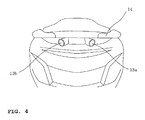
- FIG. 1 is a back view of a motorcycle 10 provided with the rearview recognition apparatus.
- a pair of rearview mirrors 11 a, 11 b are mounted to the right and left sides of a handlebar 12.
- a pair of right and left imaging devices 13a, 13b are located for capturing images of the right and left rear-side views of the vehicle.
- FIG. 2 is a view to describe an area where the imaging device 13a mounted to the right side of the vehicle can capture the image.
- the imaging device 13a is set to capture an image of area including a first area (A) recognized with the right rearview mirror 11 a and a second area (B) located right of the first area (A) relative to the vehicle 10.
- the second area (B) corresponds to an area called a blind spot where the rider cannot see with the rearview mirror 11 a.
- FIG. 3 shows a basic construction of the rearview recognition apparatus, which includes the rearview mirror 11 a for recognizing the right rear-side view (a rearview mirror 11 b for recognizing the left rear-side view is not shown) and a display screen 20 mounted to the upper part of a front cowling 15.
- the display screen 20 displays any of the images captured with the imaging devices 13a, 13b.
- Each image includes a section 21 for displaying the first area (A) and a section 22 for displaying the second area.
- FIG. 4 shows an example in which the imaging devices 13a, 13b are actually mounted at the rear part of the vehicle.
- the imaging devices 13a, 13b constituted with CCDs are mounted below the rearmost part of the grab bar 14.
- the CCD is so small that it may be selectively disposed with some flexibility.
- the imaging devices can be set to capture an image in a desirable area range.
- the imaging devices 13a, 13b are preferably angled downward toward the rear such that the imaging devices can cover an area corresponding to the blind spot on the right and left rear sides as widely as possible.
- FIG. 2 illustrates a hypothetical circumstance where a rider's motorcycle 10 running on a first lane (I) is going to change to a second lane (II).
- second lane (II) On the second lane (II), other running vehicles 30a, 30b, 30c are diagonally behind the rider's motorcycle 10 while on the first lane (I), another motorcycle 31 is running right behind the rider's motorcycle 10.
- the imaging device 13a located on the rear right side of the vehicle presets a range to capture an image including not only the area shown by angle A (first area) but also at least the area shown by angle B (second area).
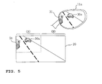
- FIG. 5 shows another vehicle 30a running on the lane (II) (assuming that no other vehicles 30b, 30c are running) which is reflected on the rearview mirror 11 a, and its image displayed on the display screen 20.
- FIG. 5 only shows a relative positional relationship between the rearview mirror 11a and the display screen 20.
- the display screen 20 displays the image captured with the imaging device associated with the turn signal in operation.
- the object reflected on the rearview mirror 11 a is almost faithfully reproduced on the area A of the display screen 20 while the image of the blind spot for the rearview mirrors is displayed on the area B.
- the rider can easily determine whether the display screen 20 displays the image of the right- or left-side view with respect to the image of the area in the direction immediately rearward of the vehicle. For example, as shown in FIG. 5, when the motorcycle 31 is running behind the rider's motorcycle 10 on the lane (I), the motorcycle 31 (or part of the motorcycle 31) behind the motorcycle 10 is displayed on the left-end side of the area A of the display screen 20. This allows the rider to instantly determine that the display screen 20 displays the image of the right rear-side view.
- the rider can recognize only using the rearview mirror 11a the position of another vehicle 30a running far behind his/her motorcycle 10. This allows the rider to make sure a relative distance between his/her motorcycle 10 and another vehicle without checking the display screen 20.
- the rider operates the right turn signal and then the display screen 20 displays the image of the right rear-side view. The rider can thus rerecognize that there is no other running vehicles displayed on the area B of the display screen 20 or the blind spot.
- the size of the image to be displayed on the area A of the display screen 20 may be preset approximately equal to the size of the object reflected on the rearview mirror 11 a. This helps the rider see the enlarged image displayed on the area A without feeling any discomfort, upon moving his/her line-of-sight from the rearview mirror 11 a reflecting the object to the display screen 20.
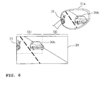
- FIG. 6 shows another vehicle 30b running on the lane (II) (assuming that no other vehicles 30a, 30c are running) which is reflected on the rearview mirror 11 a, and its image displayed on the display screen 20.
- another vehicle 30b running on the lane (II) looks big in the rearview mirror 11 a, so that the rider can recognize that the relative distance between his/her motorcycle 10 and another vehicle 30b is short. Also in such a case, when the motorcycle 10 is going to change the lanes, the rider operates the right tum signal and then the display screen 20 displays the image of the right rear-side view. Thus, seeing the area B of the display screen 20, the rider can rerecognize that there are no other vehicles running in the blind spot.
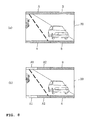
- FIG. 7 shows another vehicle 30c running on the lane (II) (assuming that no other vehicles 30a, 30b are running) which is reflected on the rearview mirror 11 a, and its image displayed on the display screen 20.
- a pair of the right and left imaging devices 13a, 13b provided on the vehicle capture an image of area including the area A (first area) recognized with the rearview mirrors 11a, 11b and the area B (second area) corresponding to the blind spot for the rearview mirrors. This allows these two areas to be displayed on the display screen 20 at the same time.
- the rider sees the image on the display screen 20 to recognize the rear-side view of the vehicle, he/she can instantly recognize the area B corresponding to the blind spot for the rearview mirrors according to the area A recognized with the rearview mirrors 11 a, 11 b.
- the rider mainly uses the rearview mirrors 11 a, 11 b to recognize the rear-side view of the vehicle while driving, so that the object reflected on the rearview mirrors 11 a, 11 b remains as memory for the rider even when he/she moves his/her line-of-sight to the display screen 20.
- This allows the rider to instantly recognize the information on the area B corresponding to the blind spot where the rider cannot see with the rearview mirrors, so that the rider can more certainly recognize the rear-side view of the vehicle while driving.
- the display screen In conjunction with operations of either one of the right and left turn signals, the display screen only displays the image captured with the imaging device 20 that is associated with the turn signal in operation, which allows the rider to instantly determine whether the display screen 20 provides information on the right or left side. This is because the rider can remember which turn signal he/she operated, and therefore can automatically recognize that the display screen 20 displays the image associated with the direction indicated by the turn signal. This allows the rider to more certainly recognizing the rear-side view of the vehicle while driving.
- the display screen 20 may be designed to indicate a mark to distinguish the area A (first area) recognized with the rearview mirrors 11a, 11b from the area B (second area) corresponding to the blind spot for the rearview mirrors. This helps the rider easily determine the image on the area A or the area B.
- each of the strip-shaped rectangular sections to be indicated along top and bottom edges of the display screen 20 may be shown in different colors between the area A and the area B.
- the area B corresponds to the blind spot. So, if the image of another vehicle appears on the area B of the display screen, the rider can recognize that another vehicle approaches his/her motorcycle.
- the area B may be shown in red, which helps the rider pay more attention to checking the rear side of the vehicle.
- the area A may be further divided into two, A1 and A2.
- the area A1 may be shown in blue while the area A2 may be shown in yellow, so that the rider can distinguish the colors and easily determine, based on the color, how close another vehicle approaches his/her motorcycle from behind.
- the images respectively captured with the right and left imaging devices 13a, 13 may be each displayed on the right and left sections of the display screen 20.
- the image captured with the right imaging device 13a is displayed on the right section 20a of the display screen 20.
- the image captured with the left imaging device 13b is displayed on the left section 20b of the display screen 20. Displaying the images in the manner described above enables the rider to easily determine whether the image of the right or left side of the vehicle appears on the display screen 20 based on the section the image appears.
- step S1 whether a switch (SW) of the right turn signal is ON or OFF is detected. If ON, then whether a switch (SW) of the left turn signal is ON or OFF is detected in the step S2. If OFF, then the display screen displays the image captured with the right imaging device (step S3). If OFF in the step S1, then whether the switch (SW) of the left turn signal is ON or OFF is detected in the step S4. If ON, then the display screen displays the image captured with the left imaging device (step S5).
- FIG. 11 illustrates a basic configuration of the rearview recognition apparatus.
- a display control section 41 e.g. MCU
- the selected image is flipped horizontal on the display screen 20 with the display control section 41.
- the display screen can display the image with the same phase as the object reflected on the rearview mirror.
- the present embodiment can provide a rearview recognition apparatus for a motorcycle which ensures high visibility of a rearview mirror while allowing a rider to instantly recognize information on the right and left rear sides of the vehicle as well as on a blind spot for the rearview mirrors.
- a rearview recognition apparatus for a motorcycle including a pair of rearview mirrors mounted to the right and left sides of a handlebar for recognizing the rear-side view of the vehicle, the apparatus having: a pair of imaging devices provided on the right and left sides of the vehicle for capturing images of the right and left rear-side views of the vehicle; and a display screen for displaying the images captured with the imaging devices, in which each of the imaging devices is set to capture an image of area including a first area recognized with the rearview mirror and a second area located on the side of the first area relative to the vehicle, and in which the display screen displays the first and second areas so that the rider recognizes the rear-side view of the vehicle.
- the display screen displays, in conjunction with operations of either one of right and left turn signals, the image captured with either one of the right and left imaging devices that is associated with the turn signal in operation.
- the display screen indicates a distinguishing mark for distinguishing the first area from the second area.
- the distinguishing mark is preferably indicated such that at least one of rectangular sections to be indicated along top and bottom edges of the display screen is shown in different colors.
- the first area includes at least an area in the direction immediately reward of the vehicle.
- the second area corresponds to a blind spot for the rearview mirrors.
- the display screen displays the image captured with the imaging device and flipped horizontally.
- the size of the image to be displayed on the first area is approximately equal to the size of an object reflected on the rearview mirror.
- the images respectively captured with the right and left imaging devices are each displayed on the right and left sections of the display screen.
- the pair of right and left imaging devices are individually located below the rearmost part of a grab bar of the vehicle.
- the motorcycle of the embodiments is provided with the aforementioned rearview recognition apparatus.
- a pair of the right and left imaging devices provided on the vehicle capture an image of area including the area recognized with the rearview mirrors and the area corresponding to the blind spot for the rearview mirrors. This allows these two areas to be displayed on the display screen at the same time.
- the rider sees the image on the display screen to recognize the rear-side view of the vehicle, he/she can instantly recognize the area corresponding to the blind spot for the rearview mirrors according to the area recognized with the rearview mirrors.
- the rider mainly uses the rearview mirrors to recognize the rear-side view of the vehicle while driving, so that the object reflected on the rearview mirrors remains as memory for the rider even when he/she moves his/her line-of-sight to the display screen. This allows the rider to instantly recognize the information on the area corresponding to the blind spot where the rider cannot see with the rearview mirrors.
- the display screen In conjunction with operations of either one of the right and left turn signals, the display screen only displays the image captured with the imaging device that is associated with the turn signal in operation, which allows the rider to instantly determine whether the display screen provides information on the right or left side. This is because the rider can remember which turn signal he/she operated, and therefore can automatically recognize that the display screen displays the image associated with the direction indicated by the turn signal.
- a rearview recognition apparatus for a motorcycle which ensures high visibility of a rearview mirror while allowing a rider to instantly recognize information on the right and left rear sides of the vehicle as well as on a blind spot for the rearview mirrors.
- a pair of imaging devices 13a, 13b for capturing images of the right and left rear-side views of the vehicle; and a display screen 20 for displaying the images captured with the imaging devices are provided.
- Each of the imaging devices is set to capture an image of area including a first area recognized with the right or left rearview mirror 11 a or 11 b and a second area (blind spot) located on the side of the first area relative to the vehicle.
- the display screen 20 displays, in conjunction with operations of either one of left and right turn signals, the image of the first and second areas captured with the imaging device that is associated with the turn signal in operation, so that the rider can recognize the rear-side view of the vehicle.
Applications Claiming Priority (2)
| Application Number | Priority Date | Filing Date | Title |
|---|---|---|---|
| JP2004295386 | 2004-10-07 | ||
| JP2005274755A JP2006131213A (ja) | 2004-10-07 | 2005-09-21 | 自動二輪車の後方視認装置 |
Publications (3)
| Publication Number | Publication Date |
|---|---|
| EP1647447A2 true EP1647447A2 (fr) | 2006-04-19 |
| EP1647447A3 EP1647447A3 (fr) | 2011-03-09 |
| EP1647447B1 EP1647447B1 (fr) | 2014-03-12 |
Family
ID=35809697
Family Applications (1)
| Application Number | Title | Priority Date | Filing Date |
|---|---|---|---|
| EP05021955.9A Not-in-force EP1647447B1 (fr) | 2004-10-07 | 2005-10-07 | Système de rétroviseur pour un véhicule |
Country Status (4)
| Country | Link |
|---|---|
| EP (1) | EP1647447B1 (fr) |
| JP (1) | JP2006131213A (fr) |
| ES (1) | ES2453491T3 (fr) |
| TW (1) | TWI275504B (fr) |
Cited By (7)
| Publication number | Priority date | Publication date | Assignee | Title |
|---|---|---|---|---|
| US20130038735A1 (en) * | 2010-03-26 | 2013-02-14 | Honda Motor Co., Ltd | System for assisting driving of vehicle |
| GB2559828A (en) * | 2017-10-12 | 2018-08-22 | Andrew Ransom Steven | Vehicle camera system |
| EP3466763A4 (fr) * | 2016-05-25 | 2019-12-04 | Mitsuba Corporation | Système de surveillance de véhicule |
| WO2020041191A1 (fr) * | 2018-08-20 | 2020-02-27 | Indian Motorcycle International, LLC | Système et procédé de notification de véhicule à roues |
| DE112018007317B4 (de) | 2018-03-20 | 2023-03-02 | Honda Motor Co., Ltd. | Fahrzeug vom Grätschsitz-Typ |
| WO2023166475A1 (fr) * | 2022-03-04 | 2023-09-07 | Piaggio & C. S.P.A. | Motocyclette avec dispositif radar |
| US11866042B2 (en) | 2018-08-20 | 2024-01-09 | Indian Motorcycle International, LLC | Wheeled vehicle adaptive speed control method and system |
Families Citing this family (5)
| Publication number | Priority date | Publication date | Assignee | Title |
|---|---|---|---|---|
| JP4948115B2 (ja) * | 2006-10-18 | 2012-06-06 | ヤマハ発動機株式会社 | 後方視認装置 |
| JP2014083963A (ja) * | 2012-10-23 | 2014-05-12 | Bridgestone Cycle Co | 自転車 |
| KR101625498B1 (ko) * | 2014-12-09 | 2016-05-30 | 김미선 | 이륜 차량용 상황 모니터링 장치 |
| CN105905200A (zh) * | 2016-06-15 | 2016-08-31 | 林海股份有限公司 | 带有后视镜角度调整结构的摩托车转向装置 |
| JP6921316B2 (ja) * | 2018-05-16 | 2021-08-18 | 三菱電機株式会社 | 車両用画像処理装置および画像処理方法 |
Citations (2)
| Publication number | Priority date | Publication date | Assignee | Title |
|---|---|---|---|---|
| JP2001105973A (ja) | 1999-10-13 | 2001-04-17 | Honda Motor Co Ltd | 車両の後方視認装置 |
| JP2001151016A (ja) | 1999-11-30 | 2001-06-05 | Yamaha Motor Co Ltd | 鞍乗型車両用映像表示装置 |
Family Cites Families (7)
| Publication number | Priority date | Publication date | Assignee | Title |
|---|---|---|---|---|
| JP2000071877A (ja) * | 1998-08-26 | 2000-03-07 | Nissan Motor Co Ltd | 車両用表示装置 |
| JP4394228B2 (ja) * | 1999-11-30 | 2010-01-06 | ヤマハ発動機株式会社 | 鞍乗型車両用映像表示装置 |
| DE10043099A1 (de) * | 2000-09-01 | 2002-03-28 | Volkswagen Ag | Verfahren und Vorrichtung zur Überwachung des rückwärtigen Bereichs eines Kraftfahrzeugs |
| JP3916958B2 (ja) * | 2002-01-24 | 2007-05-23 | クラリオン株式会社 | 車両後方モニタシステムおよびモニタ装置 |
| JP3876761B2 (ja) * | 2002-05-20 | 2007-02-07 | 日産自動車株式会社 | 車両用周辺監視装置 |
| KR20040033675A (ko) * | 2002-10-15 | 2004-04-28 | 여태순 | 자동차용 후방 감시 장치 |
| US7353086B2 (en) * | 2002-11-19 | 2008-04-01 | Timothy James Ennis | Methods and systems for providing a rearward field of view for use with motorcycles |
-
2005
- 2005-09-21 JP JP2005274755A patent/JP2006131213A/ja active Pending
- 2005-10-04 TW TW094134685A patent/TWI275504B/zh not_active IP Right Cessation
- 2005-10-07 EP EP05021955.9A patent/EP1647447B1/fr not_active Not-in-force
- 2005-10-07 ES ES05021955.9T patent/ES2453491T3/es active Active
Patent Citations (2)
| Publication number | Priority date | Publication date | Assignee | Title |
|---|---|---|---|---|
| JP2001105973A (ja) | 1999-10-13 | 2001-04-17 | Honda Motor Co Ltd | 車両の後方視認装置 |
| JP2001151016A (ja) | 1999-11-30 | 2001-06-05 | Yamaha Motor Co Ltd | 鞍乗型車両用映像表示装置 |
Cited By (15)
| Publication number | Priority date | Publication date | Assignee | Title |
|---|---|---|---|---|
| US20130038735A1 (en) * | 2010-03-26 | 2013-02-14 | Honda Motor Co., Ltd | System for assisting driving of vehicle |
| US9160981B2 (en) * | 2010-03-26 | 2015-10-13 | Honda Motor Co., Ltd. | System for assisting driving of vehicle |
| US10863141B2 (en) | 2016-05-25 | 2020-12-08 | Mitsuba Corporation | Vehicle monitor system |
| EP3466763A4 (fr) * | 2016-05-25 | 2019-12-04 | Mitsuba Corporation | Système de surveillance de véhicule |
| GB2559828B (en) * | 2017-10-12 | 2019-01-30 | Andrew Ransom Steven | Vehicle camera system |
| GB2567510A (en) * | 2017-10-12 | 2019-04-17 | Andrew Ransom Steven | Vehicle camera system |
| WO2019073208A1 (fr) * | 2017-10-12 | 2019-04-18 | Steven Andrew Ransom | Système de caméra de véhicule |
| GB2567510B (en) * | 2017-10-12 | 2020-01-15 | Andrew Ransom Steven | Rear view camera system |
| GB2559828A (en) * | 2017-10-12 | 2018-08-22 | Andrew Ransom Steven | Vehicle camera system |
| DE112018007317B4 (de) | 2018-03-20 | 2023-03-02 | Honda Motor Co., Ltd. | Fahrzeug vom Grätschsitz-Typ |
| US11794838B2 (en) | 2018-03-20 | 2023-10-24 | Honda Motor Co., Ltd. | Straddle type vehicle |
| WO2020041191A1 (fr) * | 2018-08-20 | 2020-02-27 | Indian Motorcycle International, LLC | Système et procédé de notification de véhicule à roues |
| CN112888623A (zh) * | 2018-08-20 | 2021-06-01 | 印度摩托车国际有限公司 | 轮式车辆通知系统及方法 |
| US11866042B2 (en) | 2018-08-20 | 2024-01-09 | Indian Motorcycle International, LLC | Wheeled vehicle adaptive speed control method and system |
| WO2023166475A1 (fr) * | 2022-03-04 | 2023-09-07 | Piaggio & C. S.P.A. | Motocyclette avec dispositif radar |
Also Published As
| Publication number | Publication date |
|---|---|
| EP1647447A3 (fr) | 2011-03-09 |
| TW200626392A (en) | 2006-08-01 |
| JP2006131213A (ja) | 2006-05-25 |
| EP1647447B1 (fr) | 2014-03-12 |
| TWI275504B (en) | 2007-03-11 |
| ES2453491T3 (es) | 2014-04-08 |
Similar Documents
| Publication | Publication Date | Title |
|---|---|---|
| EP1647447B1 (fr) | Système de rétroviseur pour un véhicule | |
| US11679719B2 (en) | Vehicular vision system with console video display and mirror video display for exterior viewing cameras | |
| US11285877B2 (en) | Vehicular vision system | |
| US11247609B2 (en) | Vehicular vision system | |
| US20200244929A1 (en) | Vehicular driving assistance system | |
| JP3511892B2 (ja) | 車両用周囲モニタ装置 | |
| US6447128B1 (en) | Rearview mirror assembly for a vehicle with monitor | |
| EP2045133B1 (fr) | Appareil de surveillance périphérique d'un véhicule et procédé d'affichage d'images | |
| US11851080B2 (en) | Vehicular driver monitoring system with posture detection and alert | |
| US7734417B2 (en) | Image processing device and method for parking support | |
| US6348858B2 (en) | Method and device for surveillance of the rearward observation area of motor vehicles | |
| JP2002225629A (ja) | 車両用監視装置 | |
| JP2000242896A (ja) | モニタ装置 | |
| JP2008018760A (ja) | 運転支援装置 | |
| JP2001076298A (ja) | 車両の表示装置 | |
| CN113165667A (zh) | 调节摄像机的视角的车辆用全景监控系统及其方法 | |
| KR20060080648A (ko) | 자동차의 백미러 대체용 측방 및 후방 감지 시스템 | |
| JP3485165B2 (ja) | 車両用バックモニタ装置 | |
| CN100406336C (zh) | 二轮摩托车的后视装置 | |
| JP3764317B2 (ja) | 車載用周辺視認装置 | |
| JP2003087781A (ja) | 車両周辺環境表示装置 | |
| JP2005086754A (ja) | 車輌周辺視認装置 | |
| EP1477364A1 (fr) | Un dispositif de rétroviseur extérieur | |
| JP2001063461A (ja) | 車両用後方監視カメラ | |
| KR19990034188A (ko) | 차량의 장애물 영상화면 출력장치 |
Legal Events
| Date | Code | Title | Description |
|---|---|---|---|
| PUAI | Public reference made under article 153(3) epc to a published international application that has entered the european phase |
Free format text: ORIGINAL CODE: 0009012 |
|
| AK | Designated contracting states |
Kind code of ref document: A2 Designated state(s): AT BE BG CH CY CZ DE DK EE ES FI FR GB GR HU IE IS IT LI LT LU LV MC NL PL PT RO SE SI SK TR |
|
| AX | Request for extension of the european patent |
Extension state: AL BA HR MK YU |
|
| PUAL | Search report despatched |
Free format text: ORIGINAL CODE: 0009013 |
|
| AK | Designated contracting states |
Kind code of ref document: A3 Designated state(s): AT BE BG CH CY CZ DE DK EE ES FI FR GB GR HU IE IS IT LI LT LU LV MC NL PL PT RO SE SI SK TR |
|
| AX | Request for extension of the european patent |
Extension state: AL BA HR MK YU |
|
| 17P | Request for examination filed |
Effective date: 20110906 |
|
| AKX | Designation fees paid |
Designated state(s): AT BE BG CH CY CZ DE DK EE ES FI FR GB GR HU IE IS IT LI LT LU LV MC NL PL PT RO SE SI SK TR |
|
| 17Q | First examination report despatched |
Effective date: 20120127 |
|
| GRAP | Despatch of communication of intention to grant a patent |
Free format text: ORIGINAL CODE: EPIDOSNIGR1 |
|
| INTG | Intention to grant announced |
Effective date: 20130927 |
|
| GRAS | Grant fee paid |
Free format text: ORIGINAL CODE: EPIDOSNIGR3 |
|
| GRAA | (expected) grant |
Free format text: ORIGINAL CODE: 0009210 |
|
| AK | Designated contracting states |
Kind code of ref document: B1 Designated state(s): AT BE BG CH CY CZ DE DK EE ES FI FR GB GR HU IE IS IT LI LT LU LV MC NL PL PT RO SE SI SK TR |
|
| REG | Reference to a national code |
Ref country code: GB Ref legal event code: FG4D |
|
| REG | Reference to a national code |
Ref country code: CH Ref legal event code: EP |
|
| REG | Reference to a national code |
Ref country code: AT Ref legal event code: REF Ref document number: 656046 Country of ref document: AT Kind code of ref document: T Effective date: 20140315 |
|
| REG | Reference to a national code |
Ref country code: ES Ref legal event code: FG2A Ref document number: 2453491 Country of ref document: ES Kind code of ref document: T3 Effective date: 20140408 |
|
| REG | Reference to a national code |
Ref country code: IE Ref legal event code: FG4D |
|
| REG | Reference to a national code |
Ref country code: DE Ref legal event code: R096 Ref document number: 602005042902 Country of ref document: DE Effective date: 20140424 |
|
| REG | Reference to a national code |
Ref country code: NL Ref legal event code: VDEP Effective date: 20140312 |
|
| PG25 | Lapsed in a contracting state [announced via postgrant information from national office to epo] |
Ref country code: LT Free format text: LAPSE BECAUSE OF FAILURE TO SUBMIT A TRANSLATION OF THE DESCRIPTION OR TO PAY THE FEE WITHIN THE PRESCRIBED TIME-LIMIT Effective date: 20140312 |
|
| REG | Reference to a national code |
Ref country code: AT Ref legal event code: MK05 Ref document number: 656046 Country of ref document: AT Kind code of ref document: T Effective date: 20140312 |
|
| REG | Reference to a national code |
Ref country code: LT Ref legal event code: MG4D |
|
| PG25 | Lapsed in a contracting state [announced via postgrant information from national office to epo] |
Ref country code: FI Free format text: LAPSE BECAUSE OF FAILURE TO SUBMIT A TRANSLATION OF THE DESCRIPTION OR TO PAY THE FEE WITHIN THE PRESCRIBED TIME-LIMIT Effective date: 20140312 Ref country code: CY Free format text: LAPSE BECAUSE OF FAILURE TO SUBMIT A TRANSLATION OF THE DESCRIPTION OR TO PAY THE FEE WITHIN THE PRESCRIBED TIME-LIMIT Effective date: 20140312 Ref country code: SE Free format text: LAPSE BECAUSE OF FAILURE TO SUBMIT A TRANSLATION OF THE DESCRIPTION OR TO PAY THE FEE WITHIN THE PRESCRIBED TIME-LIMIT Effective date: 20140312 |
|
| PG25 | Lapsed in a contracting state [announced via postgrant information from national office to epo] |
Ref country code: LV Free format text: LAPSE BECAUSE OF FAILURE TO SUBMIT A TRANSLATION OF THE DESCRIPTION OR TO PAY THE FEE WITHIN THE PRESCRIBED TIME-LIMIT Effective date: 20140312 |
|
| PG25 | Lapsed in a contracting state [announced via postgrant information from national office to epo] |
Ref country code: BG Free format text: LAPSE BECAUSE OF FAILURE TO SUBMIT A TRANSLATION OF THE DESCRIPTION OR TO PAY THE FEE WITHIN THE PRESCRIBED TIME-LIMIT Effective date: 20140612 Ref country code: IS Free format text: LAPSE BECAUSE OF FAILURE TO SUBMIT A TRANSLATION OF THE DESCRIPTION OR TO PAY THE FEE WITHIN THE PRESCRIBED TIME-LIMIT Effective date: 20140712 Ref country code: NL Free format text: LAPSE BECAUSE OF FAILURE TO SUBMIT A TRANSLATION OF THE DESCRIPTION OR TO PAY THE FEE WITHIN THE PRESCRIBED TIME-LIMIT Effective date: 20140312 Ref country code: RO Free format text: LAPSE BECAUSE OF FAILURE TO SUBMIT A TRANSLATION OF THE DESCRIPTION OR TO PAY THE FEE WITHIN THE PRESCRIBED TIME-LIMIT Effective date: 20140312 Ref country code: BE Free format text: LAPSE BECAUSE OF FAILURE TO SUBMIT A TRANSLATION OF THE DESCRIPTION OR TO PAY THE FEE WITHIN THE PRESCRIBED TIME-LIMIT Effective date: 20140312 Ref country code: EE Free format text: LAPSE BECAUSE OF FAILURE TO SUBMIT A TRANSLATION OF THE DESCRIPTION OR TO PAY THE FEE WITHIN THE PRESCRIBED TIME-LIMIT Effective date: 20140312 Ref country code: CZ Free format text: LAPSE BECAUSE OF FAILURE TO SUBMIT A TRANSLATION OF THE DESCRIPTION OR TO PAY THE FEE WITHIN THE PRESCRIBED TIME-LIMIT Effective date: 20140312 |
|
| PG25 | Lapsed in a contracting state [announced via postgrant information from national office to epo] |
Ref country code: AT Free format text: LAPSE BECAUSE OF FAILURE TO SUBMIT A TRANSLATION OF THE DESCRIPTION OR TO PAY THE FEE WITHIN THE PRESCRIBED TIME-LIMIT Effective date: 20140312 Ref country code: PL Free format text: LAPSE BECAUSE OF FAILURE TO SUBMIT A TRANSLATION OF THE DESCRIPTION OR TO PAY THE FEE WITHIN THE PRESCRIBED TIME-LIMIT Effective date: 20140312 Ref country code: SK Free format text: LAPSE BECAUSE OF FAILURE TO SUBMIT A TRANSLATION OF THE DESCRIPTION OR TO PAY THE FEE WITHIN THE PRESCRIBED TIME-LIMIT Effective date: 20140312 |
|
| REG | Reference to a national code |
Ref country code: DE Ref legal event code: R097 Ref document number: 602005042902 Country of ref document: DE |
|
| PG25 | Lapsed in a contracting state [announced via postgrant information from national office to epo] |
Ref country code: PT Free format text: LAPSE BECAUSE OF FAILURE TO SUBMIT A TRANSLATION OF THE DESCRIPTION OR TO PAY THE FEE WITHIN THE PRESCRIBED TIME-LIMIT Effective date: 20140714 |
|
| PLBE | No opposition filed within time limit |
Free format text: ORIGINAL CODE: 0009261 |
|
| STAA | Information on the status of an ep patent application or granted ep patent |
Free format text: STATUS: NO OPPOSITION FILED WITHIN TIME LIMIT |
|
| PG25 | Lapsed in a contracting state [announced via postgrant information from national office to epo] |
Ref country code: DK Free format text: LAPSE BECAUSE OF FAILURE TO SUBMIT A TRANSLATION OF THE DESCRIPTION OR TO PAY THE FEE WITHIN THE PRESCRIBED TIME-LIMIT Effective date: 20140312 |
|
| 26N | No opposition filed |
Effective date: 20141215 |
|
| REG | Reference to a national code |
Ref country code: DE Ref legal event code: R097 Ref document number: 602005042902 Country of ref document: DE Effective date: 20141215 |
|
| PG25 | Lapsed in a contracting state [announced via postgrant information from national office to epo] |
Ref country code: MC Free format text: LAPSE BECAUSE OF FAILURE TO SUBMIT A TRANSLATION OF THE DESCRIPTION OR TO PAY THE FEE WITHIN THE PRESCRIBED TIME-LIMIT Effective date: 20140312 Ref country code: LU Free format text: LAPSE BECAUSE OF FAILURE TO SUBMIT A TRANSLATION OF THE DESCRIPTION OR TO PAY THE FEE WITHIN THE PRESCRIBED TIME-LIMIT Effective date: 20141007 |
|
| REG | Reference to a national code |
Ref country code: CH Ref legal event code: PL |
|
| REG | Reference to a national code |
Ref country code: IE Ref legal event code: MM4A |
|
| PG25 | Lapsed in a contracting state [announced via postgrant information from national office to epo] |
Ref country code: CH Free format text: LAPSE BECAUSE OF NON-PAYMENT OF DUE FEES Effective date: 20141031 Ref country code: SI Free format text: LAPSE BECAUSE OF FAILURE TO SUBMIT A TRANSLATION OF THE DESCRIPTION OR TO PAY THE FEE WITHIN THE PRESCRIBED TIME-LIMIT Effective date: 20140312 Ref country code: LI Free format text: LAPSE BECAUSE OF NON-PAYMENT OF DUE FEES Effective date: 20141031 |
|
| REG | Reference to a national code |
Ref country code: FR Ref legal event code: PLFP Year of fee payment: 11 |
|
| PG25 | Lapsed in a contracting state [announced via postgrant information from national office to epo] |
Ref country code: IE Free format text: LAPSE BECAUSE OF NON-PAYMENT OF DUE FEES Effective date: 20141007 |
|
| PG25 | Lapsed in a contracting state [announced via postgrant information from national office to epo] |
Ref country code: GR Free format text: LAPSE BECAUSE OF FAILURE TO SUBMIT A TRANSLATION OF THE DESCRIPTION OR TO PAY THE FEE WITHIN THE PRESCRIBED TIME-LIMIT Effective date: 20140613 |
|
| PG25 | Lapsed in a contracting state [announced via postgrant information from national office to epo] |
Ref country code: TR Free format text: LAPSE BECAUSE OF FAILURE TO SUBMIT A TRANSLATION OF THE DESCRIPTION OR TO PAY THE FEE WITHIN THE PRESCRIBED TIME-LIMIT Effective date: 20140312 Ref country code: HU Free format text: LAPSE BECAUSE OF FAILURE TO SUBMIT A TRANSLATION OF THE DESCRIPTION OR TO PAY THE FEE WITHIN THE PRESCRIBED TIME-LIMIT; INVALID AB INITIO Effective date: 20051007 |
|
| REG | Reference to a national code |
Ref country code: FR Ref legal event code: PLFP Year of fee payment: 12 |
|
| REG | Reference to a national code |
Ref country code: FR Ref legal event code: PLFP Year of fee payment: 13 |
|
| PGFP | Annual fee paid to national office [announced via postgrant information from national office to epo] |
Ref country code: ES Payment date: 20171121 Year of fee payment: 13 Ref country code: GB Payment date: 20171019 Year of fee payment: 13 |
|
| REG | Reference to a national code |
Ref country code: FR Ref legal event code: PLFP Year of fee payment: 14 |
|
| GBPC | Gb: european patent ceased through non-payment of renewal fee |
Effective date: 20181007 |
|
| PG25 | Lapsed in a contracting state [announced via postgrant information from national office to epo] |
Ref country code: GB Free format text: LAPSE BECAUSE OF NON-PAYMENT OF DUE FEES Effective date: 20181007 |
|
| REG | Reference to a national code |
Ref country code: ES Ref legal event code: FD2A Effective date: 20191129 |
|
| PG25 | Lapsed in a contracting state [announced via postgrant information from national office to epo] |
Ref country code: ES Free format text: LAPSE BECAUSE OF NON-PAYMENT OF DUE FEES Effective date: 20181008 |
|
| PGFP | Annual fee paid to national office [announced via postgrant information from national office to epo] |
Ref country code: DE Payment date: 20211020 Year of fee payment: 17 |
|
| PGFP | Annual fee paid to national office [announced via postgrant information from national office to epo] |
Ref country code: IT Payment date: 20211028 Year of fee payment: 17 Ref country code: FR Payment date: 20211021 Year of fee payment: 17 |
|
| REG | Reference to a national code |
Ref country code: DE Ref legal event code: R119 Ref document number: 602005042902 Country of ref document: DE |
|
| PG25 | Lapsed in a contracting state [announced via postgrant information from national office to epo] |
Ref country code: FR Free format text: LAPSE BECAUSE OF NON-PAYMENT OF DUE FEES Effective date: 20221031 Ref country code: DE Free format text: LAPSE BECAUSE OF NON-PAYMENT OF DUE FEES Effective date: 20230503 |
|
| PG25 | Lapsed in a contracting state [announced via postgrant information from national office to epo] |
Ref country code: IT Free format text: LAPSE BECAUSE OF NON-PAYMENT OF DUE FEES Effective date: 20221007 |