EP1598196B1 - Liquid container comprising a sealing jacket, and method for unsealing liquid container fitted with liquid container jacket - Google Patents
Liquid container comprising a sealing jacket, and method for unsealing liquid container fitted with liquid container jacket Download PDFInfo
- Publication number
- EP1598196B1 EP1598196B1 EP05017034A EP05017034A EP1598196B1 EP 1598196 B1 EP1598196 B1 EP 1598196B1 EP 05017034 A EP05017034 A EP 05017034A EP 05017034 A EP05017034 A EP 05017034A EP 1598196 B1 EP1598196 B1 EP 1598196B1
- Authority
- EP
- European Patent Office
- Prior art keywords
- sealing
- ink
- liquid
- liquid supply
- air vent
- Prior art date
- Legal status (The legal status is an assumption and is not a legal conclusion. Google has not performed a legal analysis and makes no representation as to the accuracy of the status listed.)
- Expired - Lifetime
Links
Images


Classifications
-
- B—PERFORMING OPERATIONS; TRANSPORTING
- B41—PRINTING; LINING MACHINES; TYPEWRITERS; STAMPS
- B41J—TYPEWRITERS; SELECTIVE PRINTING MECHANISMS, i.e. MECHANISMS PRINTING OTHERWISE THAN FROM A FORME; CORRECTION OF TYPOGRAPHICAL ERRORS
- B41J2/00—Typewriters or selective printing mechanisms characterised by the printing or marking process for which they are designed
- B41J2/005—Typewriters or selective printing mechanisms characterised by the printing or marking process for which they are designed characterised by bringing liquid or particles selectively into contact with a printing material
- B41J2/01—Ink jet
- B41J2/17—Ink jet characterised by ink handling
- B41J2/175—Ink supply systems ; Circuit parts therefor
- B41J2/17503—Ink cartridges
- B41J2/17536—Protection of cartridges or parts thereof, e.g. tape
- B41J2/1754—Protection of cartridges or parts thereof, e.g. tape with means attached to the cartridge, e.g. protective cap
-
- B—PERFORMING OPERATIONS; TRANSPORTING
- B41—PRINTING; LINING MACHINES; TYPEWRITERS; STAMPS
- B41J—TYPEWRITERS; SELECTIVE PRINTING MECHANISMS, i.e. MECHANISMS PRINTING OTHERWISE THAN FROM A FORME; CORRECTION OF TYPOGRAPHICAL ERRORS
- B41J2/00—Typewriters or selective printing mechanisms characterised by the printing or marking process for which they are designed
- B41J2/005—Typewriters or selective printing mechanisms characterised by the printing or marking process for which they are designed characterised by bringing liquid or particles selectively into contact with a printing material
- B41J2/01—Ink jet
- B41J2/17—Ink jet characterised by ink handling
- B41J2/175—Ink supply systems ; Circuit parts therefor
- B41J2/17503—Ink cartridges
- B41J2/17533—Storage or packaging of ink cartridges
-
- B—PERFORMING OPERATIONS; TRANSPORTING
- B41—PRINTING; LINING MACHINES; TYPEWRITERS; STAMPS
- B41J—TYPEWRITERS; SELECTIVE PRINTING MECHANISMS, i.e. MECHANISMS PRINTING OTHERWISE THAN FROM A FORME; CORRECTION OF TYPOGRAPHICAL ERRORS
- B41J2/00—Typewriters or selective printing mechanisms characterised by the printing or marking process for which they are designed
- B41J2/005—Typewriters or selective printing mechanisms characterised by the printing or marking process for which they are designed characterised by bringing liquid or particles selectively into contact with a printing material
- B41J2/01—Ink jet
- B41J2/17—Ink jet characterised by ink handling
- B41J2/175—Ink supply systems ; Circuit parts therefor
- B41J2/17503—Ink cartridges
- B41J2/17536—Protection of cartridges or parts thereof, e.g. tape
-
- B—PERFORMING OPERATIONS; TRANSPORTING
- B41—PRINTING; LINING MACHINES; TYPEWRITERS; STAMPS
- B41J—TYPEWRITERS; SELECTIVE PRINTING MECHANISMS, i.e. MECHANISMS PRINTING OTHERWISE THAN FROM A FORME; CORRECTION OF TYPOGRAPHICAL ERRORS
- B41J2/00—Typewriters or selective printing mechanisms characterised by the printing or marking process for which they are designed
- B41J2/005—Typewriters or selective printing mechanisms characterised by the printing or marking process for which they are designed characterised by bringing liquid or particles selectively into contact with a printing material
- B41J2/01—Ink jet
- B41J2/17—Ink jet characterised by ink handling
- B41J2/175—Ink supply systems ; Circuit parts therefor
- B41J2/17503—Ink cartridges
- B41J2/17553—Outer structure
-
- B—PERFORMING OPERATIONS; TRANSPORTING
- B41—PRINTING; LINING MACHINES; TYPEWRITERS; STAMPS
- B41J—TYPEWRITERS; SELECTIVE PRINTING MECHANISMS, i.e. MECHANISMS PRINTING OTHERWISE THAN FROM A FORME; CORRECTION OF TYPOGRAPHICAL ERRORS
- B41J2/00—Typewriters or selective printing mechanisms characterised by the printing or marking process for which they are designed
- B41J2/005—Typewriters or selective printing mechanisms characterised by the printing or marking process for which they are designed characterised by bringing liquid or particles selectively into contact with a printing material
- B41J2/01—Ink jet
- B41J2/17—Ink jet characterised by ink handling
- B41J2/175—Ink supply systems ; Circuit parts therefor
- B41J2/17503—Ink cartridges
- B41J2/17556—Means for regulating the pressure in the cartridge
-
- Y—GENERAL TAGGING OF NEW TECHNOLOGICAL DEVELOPMENTS; GENERAL TAGGING OF CROSS-SECTIONAL TECHNOLOGIES SPANNING OVER SEVERAL SECTIONS OF THE IPC; TECHNICAL SUBJECTS COVERED BY FORMER USPC CROSS-REFERENCE ART COLLECTIONS [XRACs] AND DIGESTS
- Y10—TECHNICAL SUBJECTS COVERED BY FORMER USPC
- Y10S—TECHNICAL SUBJECTS COVERED BY FORMER USPC CROSS-REFERENCE ART COLLECTIONS [XRACs] AND DIGESTS
- Y10S220/00—Receptacles
- Y10S220/916—Container including axially opposed removable closures
Definitions
- the present invention relates to a liquid container according to the preamble of claim 1, and to a method for unsealing a packaging structure according to the preamble of claim 10, wherein the features of both preambles are known from document EP 0 792 749 A .
- an ink jet recording head which ejects ink onto recording medium to form an image on the recording medium employs an ink container from which ink is supplied to the recording head through an ink supply tube or the like.
- an ink container from which ink is supplied to the recording head through an ink supply tube or the like.
- replaceable ink containers which are independent from an ink jet recording head. Many of these replaceable ink containers comprise a shell, and a piece of ink absorbing member contained in the shell in order to retain ink. They are connected to the ink supply tube leading to an ink jet recording head.
- some of the containers have been known to be structured so that the ink content of the ink absorbing member is greater in the adjacencies of the ink outlet of the ink container than in the rest of the ink container, and smallest in the adjacencies of the air vent than in the rest of the ink container.
- a sealing jacket capable of sealing the ink outlet and air vent, around the ink container, in order to prevent the ink leakage.
- a sealing jacket is placed around an ink container so that the ink outlet and air vent of the ink container are covered with the sealing jacket. Then, in order to keep the ink container hermetically sealed, the sealing jacket is glued, or thermally welded, to the ink container along the portions around the ink outlet and the portion around the air vent.
- a sealing jacket is inexpensive, and yet, is capable of reliably keeping an ink container hermetically sealed.
- a sealing jacket becomes partially undone due to the increase in the internal pressure of the ink container caused by the changes in the ambient factors.
- a conventional sealing jacket has been very firmly glued, or thermally welded, to the ink container along the portions around the ink outlet and air vent; in other words, the adhesive strength between the sealing jacket and ink container is made substantial, around the ink outlet and air vent. Therefore, a user has to apply a substantial amount of muscular force, in order to remove the sealing jacket.
- the first body of ink is subjected to the pressure which acts in the direction in which the internal volume of the ink container 51 increases, that is, in the direction in which the ink within the ink container is drawn out.
- the first body of ink is also affected by the inertia generated by the movement of the sealing jacket 52 being abruptly peeled.
- the body of ink 54 between the ink absorbent member 53 and the sealing jacket 52 is abruptly stretched by the sealing jacket 52.
- the body of ink 54 will abruptly split.
- specks of ink which fail to remain on either the ink absorbent member 53 or sealing jacket 52, splash.
- the cap 62 is welded to the ink outlet 61 at the welding seam 64 in order to assure that the ink outlet 61 remains sealed, for the purpose of preventing these bodies of ink from being splashed.
- This type of ink container 63 is to be unsealed in the following manner. First, in order to break the welding seam 64 between the cap 62 and ink outlet 61, the cap 62 is to be rotated in the direction opposite to the direction in which the cap 62 is to be rotated in the final stage of its removal. Then, the cap 62 is to be removed. Therefore, the internal pressure of the ink container 63 is not released while the cap 62 becomes literally separated from the ink outlet.
- the cap 62 is removed after the breaking of the welding seam 64, eliminating the problem that the cap 62 is abruptly moved away from the ink outlet.
- the type of ink splashing which sometimes occurs to an ink container employing the sealing jacket shown in Figure 10 , does not occur to these types of ink container, since the cap 62 of this type of ink container is opened by rotating the cap 62.
- the cap In the case of the ink containers with a cap structured as described above, the cap must be “twisted” to open it. “Twisting” means “turning the wrist while holding the cap", which is an operation rather difficult for children, older people, or people having troubles with their hands or wrists, to perform. Moreover, the cap of this type of ink container is firmly welded to assure that the ink container remains sealed with the cap, adding to the level of the difficulty in the twisting the cap. Thus, a sealing jacket for an ink container, which is structured so that an ink container can be easily unsealed by anybody, has been desired.
- the present invention is made in consideration of the above described problems, and it is the object of the invention to provide a liquid container comprising a highly reliable sealing jacket for a liquid container, which is capable of preventing ink from splashing from the ink outlet of an ink container during the unsealing of the ink container, and yet can be easily removed by anybody, and also to provide a method for unsealing a liquid container fitted with such a sealing jacket.
- the object of the invention is achieved by a liquid container according to claim 1, and by a method according to claim 10, respectively.
- a packaging structure for a liquid container including a liquid containing portion accommodating liquid, a liquid supply portion for supplying the liquid to an outside and an air vent for fluid communication with an ambience, comprising a covering member for covering and sealing said liquid supply portion and said air vent; said covering member including an air vent sealing portion for sealing said air vent and a liquid supply portion sealing portion for sealing said liquid supply portion, and a connecting region for covering a connecting side of said liquid container which connects said air vent sealing portion and said liquid supply portion sealing portion, wherein said liquid supply portion sealing portion effects non-adhering sealing for said liquid supply portion, and said connecting region provides a resistance against unsealing of said liquid supply portion.
- an unsealing method for unsealing a packaging structure for a liquid container including a liquid containing portion accommodating liquid, a liquid supply portion for supplying the liquid to an outside and an air vent for fluid communication with an ambience
- said packaging structure including a covering member for covering and sealing said liquid supply portion and said air vent; said covering member including; an air vent sealing portion for sealing said air vent and a liquid supply portion sealing portion for sealing said liquid supply portion, and a connecting region for covering a connecting side of said liquid container which connects said air vent sealing portion and said liquid supply portion sealing portion, wherein said liquid supply portion sealing portion effects non-adhering sealing for said liquid supply portion, and said connecting region provides a resistance against unsealing of said liquid supply portion, said method comprising a step of unsealing said air vent at said air vent sealing portion; a step of separating said first resistance generating portion from the side of said liquid container where said first resistance generating portion is provided; a step of unsealing said liquid supply portion at said liquid
- a packaging structure for a liquid container having a liquid containing portion for containing liquid and a liquid supply opening for supplying the liquid, wherein said liquid supply opening is covered by a covering member, wherein said covering member has at least two independent adhered regions where said covering member is adhered to said liquid container at positions such that liquid supply opening is interposed between said two adhered regions.
- a packaging structure for a liquid container having a liquid containing portion for containing liquid and a liquid supply opening for supplying the liquid, wherein said liquid supply opening is covered by a covering member, wherein said covering member has independent adhered regions where said covering member is adhered to said liquid container and tearing means for tearing said covering member at respective positions such that liquid supply opening is interposed between said regions.
- a packaging structure for a liquid container including a liquid containing portion accommodating liquid, a liquid supply portion for supplying the liquid to an outside and an air vent for fluid communication with an ambience
- the packing structure includes a covering member for covering and sealing the liquid supply portion and the air vent; the covering member including; an air vent sealing portion for sealing the air vent and a liquid supply portion sealing portion for sealing the liquid supply portion, and a connecting region for covering a connecting side of the liquid container which connects the air vent sealing portion and the liquid supply portion sealing portion, wherein the liquid supply portion sealing portion effects non-adhering sealing for the liquid supply portion, and the connecting region provides a resistance against unsealing of the liquid supply portion.
- a liquid container fitted with the above described sealing jacket can be unsealed following the steps described next.
- the sealing jacket is adhered to the liquid container by its two adherent portions positioned one for one on both sides of the liquid outlet in terms of the direction in which the sealing jacket is to be removed.
- first, one (first) of the adherent portions of the sealing jacket is peeled.
- the length of the first adherent portion in terms of the direction in which it is peeled, makes it possible for a user to realize the amount of muscular force necessary to be exerted to peel the sealing jacket, preventing therefore the sealing jacket from being peeled too fast by the application of an excessive amount of force.
- the amount of the force necessary to peel the sealing jacket suddenly reduces to virtually zero.
- the user has not been applying an excessive amount of muscular force, as described above. Therefore, it does not occur that the user's hand grasping the sealing jacket jerkingly moves due to the sudden reduction in the resistance.
- the portion of the sealing jacket corresponding to the liquid outlet of the liquid container is not adherent.
- the liquid outlet becomes unsealed.
- the sealing jacket is not abruptly peeled. Therefore, the liquid in, or adhering to, the liquid outlet is not splashed the moment the liquid outlet becomes unsealed.
- the sudden reduction, to virtually zero, of the resistance, against which the force necessary to peel the sealing jacket is being applied the user gives the user the "sense of completion" that the liquid outlet has just been unsealed.
- this sealing jacket structured as described above can also prevent the liquid on the sealing jacket itself from splashing because, the second adherent portion of the sealing jacket functions as the stopper for preventing the rest of the sealing jacket from being abruptly peeled away in "one quick stroke".
- this sealing jacket structured as described above has a sealing means positioned to hermetically seal the liquid storage portion as the sealing jacked is placed around an ink container, and also that in terms of the specific direction in which the sealing jacket is to be peeled, the first and second adherent portions of the sealing jacket are in front, and after, this sealing means, respectively.
- the air vent is desired to be in front of the sealing member, in terms of the specific direction in which the sealing jacket is to be peeled.
- the liquid container to be fitted with the sealing jacket structured as described above may be in the form of a rectangular parallelepiped.
- the shape is desired to be flat, and the liquid outlet is placed on the surface other than the largest surfaces.
- Such a liquid container is advantageous in terms of spatial efficiency, because when it is disposed in parallel by two or more, it occupies a smaller amount of space compared to a liquid container which is not in the above described form.
- a liquid container shaped as described above is desired to be covered with the above described sealing jacket, at least across the surface having the ink outlet and the pair of surfaces contiguous to the surface having the ink outlet. Further, the first and second adherent portions of the sealing jacket for covering this liquid container correspond in position to the pair of liquid container surfaces contiguous to the surface with the liquid outlet, one for one.
- the sealing jacket is desired to be fitted around the ink container so that the second adherent portion of the sealing jacket, that is, the adherent portion positioned after the liquid outlet in terms of the specific direction in which the sealing jacket is to be peeled, covers the edge at which the liquid container surface with the liquid outlet intersects with the liquid container surface contiguous thereto.
- the second adherent portion function as the above described stopper immediately after the unsealing of the ink outlet.
- the liquid outlet is desired to be disposed close to the liquid container surface corresponding in position to the second adherent portion of the sealing jacket.
- the liquid container is desired to have a sealing member for sealing the air vent connecting the internal space of the liquid container to the ambient air.
- This sealing member may be an integral part of the sealing jacket.
- the sealing jacket is desired to be provided with a pair of perforations cut in parallel on the two sides of the sealing member, one for one, in terms of the direction in the sealing jacket is peeled.
- a sheet of film preferably, a sheet of thermally shrinkable film
- the sealing jacket may be completely wrapped around a liquid container; it may be in the form of an endless belt. Further, it may be form of elastic material.
- gluing or thermal welding may be employed as for the means for attaching the sealing jacket to a liquid container.
- a cap may be employed.
- the sealing portion of the cap is formed of elastic substance or elastomer.
- the adherent portion of a sealing jacket, which is adhered to a liquid container, and the means for cutting the sealing jacket, may be independently disposed on the opposite sides with respect to the ink outlet. Such a design can also accomplish the above described objects of the present invention.
- a packaging structure for a liquid container including a liquid containing portion accommodating liquid, a liquid supply portion for supplying the liquid to an outside and an air vent for fluid communication with an ambience, comprising:
- a packaging structure wherein said liquid container is substantially in the form of a rectangular parallelopiped shape substantially constituted by six sides, and said air vent and said liquid supply portion are disposed in opposite ones of said sides, wherein said covering member has a first region and a second region covering opposite sides connecting the side having said air vent and the side having said liquid supply portion, respectively, and said first region and said second region include a first resistance generating portion against unsealing and a second resistance generating portion against the unsealing.
- a packaging structure wherein said first and second regions of said covering member is partly adhered to said liquid container to provide said first and second resistance generating portion, so that peeling resistance of the adhered portion provides a resistance against unsealing.
- a packaging structure wherein said first region of said covering member is adhered to said liquid container to provide a resistance against peeling, and said second region of said covering member has a perforation to provide a degree of resistance against tearing, wherein said resistance against peeling and said resistance against tearing provide the resistance against unsealing.
- a packaging structure wherein said covering member is removed from said air vent, said first unsealing resistance generating portion, said liquid supply portion and said second unsealing resistance generating portion, in the order named.
- a packaging structure wherein said liquid supply portion sealing portion is provided with a capping member having an elastic member elastically covering said liquid supply portion, wherein said liquid supply portion is sealed by said elastic member using said covering member.
- a packaging structure wherein said air vent sealing portion seals said air vent using bonding or welding.
- a packaging structure wherein said first and second unsealing resistance generating portion extends to a neighborhood of a corner constituted by the side having said liquid supply portion and the side connecting therewith.
- a packaging structure wherein said liquid supply portion is disposed adjacent the side having said first and second unsealing resistance generating portion.
- An unsealing method for unsealing a packaging structure for a liquid container including a liquid containing portion accommodating liquid, a liquid supply portion for supplying the liquid to an outside and an air vent for fluid communication with an ambience, said packaging structure including a covering member for covering and sealing said liquid supply portion and said air vent; said covering member including; an air vent sealing portion for sealing said air vent and a liquid supply portion sealing portion for sealing said liquid supply portion, and a connecting region for covering a connecting side of said liquid container which connects said air vent sealing portion and said liquid supply portion sealing portion, wherein said liquid supply portion sealing portion effects non-adhering sealing for said liquid supply portion, and said connecting region provides a resistance against unsealing of said liquid supply portion, said method comprising:
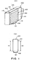
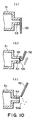
- Figure 1 is a drawing for describing the overall structure of the first embodiment of an ink container in accordance with the present invention, Figures 1(a) and 1(b) being perspective and front views the container, respectively.
- the ink container 100 in Figure 1 comprises: an ink container proper 101 for holding ink; an ink outlet 102 through which ink is supplied outward (for example, toward ink jet recording head); an air vent 104 through which air is introduced or expelled; a sealing member 105 for sealing the air vent 104; and a sealing jacket 103 for covering the entirety of the ink container proper 101 as well as the ink outlet 102.
- the sealing jacket 103 comprises a cap 121 for sealing the ink outlet 102; and a wrapping member 120 which wraps the ink container proper 101 as well as the cap 121.
- the sealing member 105 may be an integral part of the wrapping member 120.
- the wrapping member 120 has first and second portions 110 and 111, respectively, coated with adhesive, which hereinafter will be referred to as first and second adherent portions ( Figure 1(b) ).
- the wrapping member 120 is pictured as a transparent member, and the adherent portions 110 and 111 are hatched.
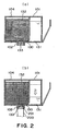
- Figure 2 is a sectional view of the ink container proper 101 at a plane parallel to the largest wall thereof.
- the ink container proper 101 is in the form of a parallelepiped, and is relatively flat.
- the internal space comprises two chambers: a chamber 130 in which a negative pressure generating member is held, and ink storage chamber 131 located next to the negative pressure generating member holding chamber 130.
- the negative pressure generating member absorbs and retains ink by generating negative pressure, and the ink storage chamber 131 holds ink.
- the partition wall partitioning the negative pressure generating member holding chamber 130 from the ink storage chamber 131 has a passage through which the two chambers are in connection with each other, and which is located at the edge of the negative pressure generating member holding chamber 130 next to the bottom wall of the ink container proper 101.
- the negative pressure generating member holding chamber 130 has the ink outlet 120 and air vent 104.
- the ink outlet 120 is attached to the bottom wall thereof.
- the air vent 104 is the passage between the internal space of the ink container proper 101 and the ambience, and is in the ceiling portion of the negative pressure generating member holding chamber 130.
- the ink outlet 102 is filled with a compressed member 133, as an ink drawing member, for efficiently drawing ink into the ink supply tube leading to the ink jet recording head.
- the ink drawing tube 200 of the main assembly of the image forming apparatus enters the ink outlet 102, pressing on the compressed member 133.
- Some of the ink drawing tubes 200 have a filter 201, which is attached to the opening of the ink drawing tube 200 as shown in the drawing. Then, as the ink jet recording apparatus is operated, ink is ejected from the ink jet recording head (unshown), generating such force that suctions the ink from the ink container proper 101.
- the ink in the ink storage chamber 131 is drawn into the negative pressure generating member holding chamber 130, and then, is further drawn into the ink supply tube 200 through the negative pressure generating member 132, being thereby supplied to the ink jet recording head. Consequently, the internal pressure of the ink storage chamber 131 drops, creating pressure difference between the ink storage chamber 131 and negative pressure generating member holding chamber 130. This pressure difference temporarily increases as the ink is continuously supplied to the ink jet recording head due to its recording operation.
- the negative pressure generating member holding chamber 130 has the air vent 104, through which the negative pressure generating member holding chamber 130 is open to the ambience, the ambient air enters the ink storage chamber 131 through the negative pressure generating member holding chamber 130, neutralizing the pressure difference between the ink storage chamber 131 and negative pressure generating member holding chamber 130. During the image forming operation, this creation and neutralizing of the pressure difference is repeated, making it possible for the ink to be smoothly supplied to the ink jet recording head.
- the air vent 104 is in the wall of the ink container proper 101, which opposes the wall of the ink container proper 101 having the ink outlet 102. It is open immediately adjacent to the negative pressure generating member 132.
- the sealing member 105 for sealing the air vent 104 is in the form of a piece of film, and is on the wall of the ink container proper 101, which has the air vent 104, being glued thereto in a manner to seal the air vent 104.
- the sealing member 105 should be off the ink container proper 101 when mounting the ink container 100 into the ink jet recording apparatus (unshown). Therefore, the sealing member 105 is attached to the ink container proper 101 using such an adhesive, or welding method, that allows it to be peeled away from the ink container proper 101 when necessary.
- FIG 3 is a perspective view of the sealing jacket 103 for sealing the ink container proper 101 as shown in Figure 1 .
- the hatched portions in the drawing represent the portions of the sealing jacket 103 by which the sealing jacket 103 is attached to the ink container proper 101.
- the sealing jacket 103 is in the form of an endless belt or band as shown in Figure 3 .
- the sealing jacket 103 comprises the cap 121 and wrapping belt portion 120.
- the cap 121 is positioned so that it fits around the ink outlet 102 of the ink container proper 101 as the ink container proper 101 is wrapped with the sealing jacket 103.
- the material for the cap 121 is different from the material for the wrapping belt portion 120.
- the cap 121 is a member to be pressed on the ink outlet 102 to seal the ink container proper 101. Therefore, an easily pliable elastomer is desirable as the material for the cap 121.
- the cap 121 of this embodiment is formed of two materials. That is, the portion of the cap 121 which is placed in contact with the ink outlet 102 to seal the ink container proper 101 is formed of elastomer, whereas the portion of the cap 121 surrounding the portion formed of elastomer is formed of polypropylene ( Figure 4 ).
- the cap 121 is fixed to the wrapping belt portion 120.
- the polypropylene portion of the cap 121 surrounding the elastomer portion of the cap 121 is glued, or welded, to the wrapping belt portion 120.
- the wrapping belt portion 120 and cap 121 of this embodiment are held together by welding, or with the use of adhesive, there is absolutely no problem even if a means other than welding or adhesive may be employed to hold the wrapping belt portion 120 and cap 121 together, as long as it assures that the cap 121 remains securely held by the wrapping belt portion 120.
- the wrapping belt portion 120 is desired to be such film that can be thermally shrunk to conform to the external contour of the ink container proper 101.
- the wrapping belt portion 120 may be a belt of film, one end of which can be welded to the other in a manner to form an endless belt after being wrapped around the ink container proper 101 so that the cap 121 is covered and retained by the wrapping belt portion 120.
- the sealing member 105 is an integral part of the wrapping belt portion 120, which faces the wall of the ink container proper 101 having the air vent 104.
- the sealing member 105 is differentiated from the rest of the wrapping belt portion 120 by two straight lines of perforation 115 parallel to each other.
- the wrapping belt portion 120 can be easily torn off by simply lifting the sealing member 105, exposing the air vent 104 as well as the ink outlet. In other words, the air vent 104 and ink outlet 102 can be exposed by a single action.
- the wrapping belt portion 120 is fixed to the ink container proper 101 by the two adherent portions, that is, first and second adherent portions, of the wrapping belt portion 120 corresponding, one for one, to the two lateral surfaces of the ink container proper 101 which sandwich the surface of the ink container 101 having the ink outlet 102 (surfaces contiguous to the surface having ink outlet). Since these first and second adherent portions must be peelable from the ink container proper 101 when removing the wrapping belt portion 120, they are glued, or welded, to the ink container proper 101.
- the wrapping belt portion 120 of the sealing jacket 103 is in the form of a cylinder, which is greater in circumference than the portion of the ink container proper 101 to be wrapped by the wrapping belt portion 120.
- the ink container proper 101 is placed inward of the wrapping belt portion 120.
- the ink container proper 101 and sealing jacket 103 are positioned relative each other so that the cap 121 is placed in contact with the ink outlet 102.
- the cap 121 is kept pressed on the ink outlet 102 with the use of a retaining jig (unshown), the structure of which is optional as long as it does not damage the elastomer portion 121a of the cap 121.
- the first and second adherent portions 110 and 111 coated with adhesive are pressed on the corresponding lateral surfaces of the ink container proper 101 to adhere thereto the first and second adherent portions 110 and 111.
- the wrapping belt portion 120 formed of shrinkable film is thermally shrunk, while keeping the cap 121 pressed on the ink outlet 102 with the above described retaining jig, until the sealing jacket 103 conforms to the external contour of the ink container proper 101 tightly enough for the resultant tensile force of the sealing jacket 103 to keep the ink outlet sealed by the cap 121.
- the ink container proper 101 is released from the retaining jig, ending the process for covering the ink container proper 101 with the sealing jacket 103.
- Figure 1 shows the ink container 100 after the completion of this process.
- Figure 4 is a sectional view of the ink outlet 102, and the cap 121 on the ink outlet 102, for showing how the ink outlet 102 is kept sealed by the cap 121.
- the ink container proper 101 has a cylindrical portion 150, which projects from the edge of the ink outlet 102 in a manner to surround the ink outlet.
- the internal diameter of the cylindrical portion 150 is roughly the same as the diameter of the ink outlet 102.
- the end surface of the cylindrical portion 150 has a projection 151, and the elastomer portion 121a of the cap 121, with which the collar rib 150 makes contact, has a groove 125 with a V-shaped cross section (which hereinafter may simply be referred to as V-shaped groove), into which the projection 151 of the cylindrical portion 150 fits.
- the projection 151 As the projection 151 is pressed into the V-shaped groove 125, the projection enters the V-shaped groove 125, pressing on the elastomer portion 121 as if widening the groove 125.
- the slanted surface of the V-shaped groove 125 conforms to the contour of the projection 151, airtightly sealing between the projection 151 and the slanted surface of the V-shaped groove 125.
- the ink outlet 102 is airtightly sealed.
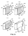
- Figure 5(a) is a perspective view of an ink container 100 in accordance with the present invention prior to the unsealing of the ink outlet 102;
- Figure 5(b) a perspective view of the same during the removal of the sealing member 105;
- Figure 5(c) a perspective view of the ink container shortly after the beginning of the peeling of the first adherent portion 110 of the wrapping belt portion 120;
- Figure 5(d) is a perspective view of the same during the advanced stage of the peeling of the first adherent portion 110 of the wrapping belt portion 120.
- Figure 6 is a frontal plan view of the ink container 100 in accordance with the present invention during the unsealing of the ink outlet 102.
- This embodiment of an ink container in accordance with the present invention is to be unsealed in the following order.
- the sealing member 105 covering the air vent 104 is to be removed to expose the air vent 104.
- This process should be carried out first for the following reason.
- the internal pressure of the ink container proper 101 sometimes becomes higher than the ambient pressure due to the changes in the ambient factors, for example, temperature. Thus, it is possible that ink will splash out of the unsealed openings of the ink container proper 101 as the ink container proper 101 is unsealed.
- a user is to remove the sealing member 105 by grasping the tab 112 ( Figure 5(a) ) of the sealing jacket 103 extending beyond the corresponding lateral surface of the ink container proper 101. Since the pair of straight perforations 115 for making it easier for the sealing member 105 to be removed border between the sealing member 105 and the rest of the sealing jacket 103, it is easy for the user to tear the sealing jacket 103 to remove the sealing member 105. The user can confirm, by finding these perforations, whether the direction in which the user is about to peel the sealing member 105 is right or wrong.
- the sealing member 105 As the sealing member 105 is pulled by the user in the direction indicated by an arrow mark A in the drawing, not only does the sealing member 105 become separated from the ink container proper 101, but also, the portion of the sealing jacket 103 between the two perforations 115 is removed. As the sealing member 105 is removed, the air vent 104 is exposed. Further, the removal of the portion of the sealing jacket 103 between the two perforations 115 gives the sealing jacket 103 a U-shaped cross section as seen from the direction parallel to its surface.
- the tab 112 of the sealing member 105 is provided with a clear marking for allowing a user to recognize the presence of the tab 112.
- the peeling of the sealing jacket 103 will be described.
- the sealing jacket 103 remains attached to the ink container proper 101, being in conformation to the external contour of the ink container proper 101, and therefore, maintaining the aforementioned U-shaped cross section ( Figure 5(b) ).
- the user is to peel the sealing jacket 103 by grasping one of the ends of the sealing jacket 103 remaining adhered to the two surfaces of the ink container proper 101 which oppose each other with the presence of the surface of the ink container proper 101 with the ink outlet 102 between them.
- the first adherent portion 110 of the sealing jacket 103 ( Figure 1(b) ), and the second adherent portion 110 of the sealing jacket 103 on the opposite side with respect to the ink container proper 101 ( Figure 1(b) ), are adhered to the ink container proper 101 from one edges to the others.
- the portions of the sealing jacket 103 next to the aforementioned perforations 115 were not made adherent. These portions of the sealing jacket 103 constitute the tab 116 for grasping the sealing jacket in order to peel the sealing jacket 103.
- This embodiment of an ink container that is, the ink container 100, is structured so that it is unnecessary to clearly indicate the direction in which the sealing jacket 103 is to be peeled; the sealing jacket 103 can be peeled from either end.
- the clockwise direction is assumed to be the right direction in which the sealing jacket 103 is to be peeled.
- the first adherent portion 110 ( Figure 1(b) ), and the second adherent portion 111 on the opposite side with respect to the ink container proper 101 ( Figure 1(b) ), are adhered from one edge to the other in terms of the widthwise direction of the sealing jacket 103, making it difficult to peel the sealing jacket 103 without using the tab 112, and therefore, compelling the user to remove the sealing jacket 103 primarily using the tab 112 defined by the present invention.
- the adherent portion 110 is to be pulled in the direction indicated by an arrow mark B as shown in Figure 5(c) .
- a user should know that the sealing jacket 103 should be gradually peeled, instead of abruptly, because the first adherent portion 110 is pasted to the surface of the ink container proper 101 by a substantial length in terms of the lengthwise direction of the sealing jacket 103.
- the user can realize the proper amount of force (stress) necessary to peel the sealing jacket 103, refraining from applying an excessive amount of force to abruptly peel the sealing jacket 103.
- the peeling of the first adherent portion 110 ends.
- the adhesive strength, between the first adherent portion 110 and corresponding surface of the ink container proper 101, against which force is applied by the user to peel the sealing jacket 103 becomes zero. Therefore, without the anticipation of the end of the peeling of the sealing jacket 103, the hand of the user may be let go suddenly in the direction indicated by the arrow mark B the moment the peeling of the first adherent portion 110 ends.
- This problem that the hand of the user grasping the sealing jacket 103 is let go abruptly in the arrow direction can be prevented by regulating the amount of the adhesive strength between the first adherent portion 110 and the corresponding wall of the ink container proper 101.
- the cap 121 which was kept by the sealing jacket 103, in the position in which it seals the ink outlet 102, is removed from the ink outlet 102 in a manner to rotate about the edge (rotational center C in Figure 6 ) of the second adherent portion 111 closest to the ink outlet 102, unsealing the ink outlet 102.
- the movement of the hand of the user remains well controlled, that is, the user's hand does not move jerkingly.
- the second adherent portion 111 functions as the stopper for preventing the abrupt peeling of the sealing jacket 103, that is, the cause of the splashing of the ink on the sealing surface of the cap 121, preventing therefore the ink on the sealing surface of the cap 121 from being splashed.
- the stopper, or the second adherent portion 111 function as soon as the ink outlet is unsealed, it is desired that the bottom edge of the adherent portion 111 coincides with the edge between the surface of the ink container proper 101 to which the second adherent portion 111 is adhered, and the surface of the ink container proper 101 having the ink outlet 102.
- the ink outlet 102 should be disposed adjacent to the surface of the ink container proper 101 to which the adherent portion 111 is adhered. Further, in order to ensure that the second adherent portion 111 stops the peeling action, the adhesive strength between the second adherent portion 111 and the corresponding surface of the ink container proper 101 should be greater than that between the first adherent portion 110 and the corresponding surface of the ink container proper 101.
- the cap 121 will be held close to the ink outlet 102, almost directly facing the opening of the ink outlet 102. Therefore, should the ink be splashed from the cap 121, the splashed ink flies into the cap 121, being trapped therein, and therefore, being prevented from being splashed beyond the cap 121 and sealing jacket 103.
- this embodiment of an ink container, or the ink container 100 has been designed so that the direction, in which the sealing jacket 103 will be pulled just before the ink outlet 102 begins to be unsealed, becomes virtually perpendicular to the surface of the ink container proper 101 having the ink outlet 102. This is for the following reason. The moment the peeling of the first adherent portion 110 of the sealing jacket 103 is completed, the force applied to peel the first adherent portion 110 turns into such force that works in the direction to shear the second adherent portion 111. Thus, the above described design is employed to make it rather difficult to remove the second adherent portion 111.
- Figure 13(a) shows the ink container 100, the sealing jacket 103 of which is extended as far as it can be extended, in the direction indicated by an arrow mark E, which is parallel to the surface of the ink container proper 101 to which the first adherent portion 110 had once been adhered.
- Figure 13(b) shows the ink container 100, the sealing jacket 103 of which is being pulled in the direction indicated by an arrow mark F, which is not parallel to the surface of the ink container proper 101, to which the first adherent portion 110 had once been adhered.
- the sealing jacket 103 itself functions as an ink catcher, minimizing the contamination traceable to the ink splash.
- the second adherent portion 111 of the sealing jacket 103 is to be peeled after the unsealing of the ink outlet 102.
- the second adherent portion 111 is also adhered to the ink container proper 101 across a substantial range, as is the first adherent portion 110, in terms of the lengthwise direction of the sealing jacket 103.
- the user is to gradually peel the sealing jacket 103, while sensing the force necessary for peeling the second adherent portion 111 of the sealing jacket 103.
- the sealing surface of the cap 121 on which ink is present, can be seen. Therefore, the user is reminded that the adherent portion 111 of the sealing jacket 103 must also be cautiously peeled until the sealing jacket 103 is completely removed.
- the first and second adherent portions 110 and 111 are adhered to the ink container proper 101 across the entire range in term of the widthwise direction of the sealing jacket 103.
- they may be adhered in a different pattern such as the one shown in Figure 12 ; the employment of such a pattern causes no problem at all.
- the actions required of a user in order to unseal the ink outlet 102 of this embodiment of the present invention, that is, the ink container 100, are only to peel the sealing member 105 and to peel the sealing jacket 103 as shown in Figures 5(a) - 5(d) . In both actions, all that is required to peel them is to grasp the tab, or the tab-like portion, and pull it; in other words, anyone can easily unseal the ink outlet 102.
- Figure 7 shows the second embodiment of an ink container in accordance with the present invention.
- Figure 7(a) is a perspective view of the ink container in the unsealed state
- Figure 7(b) is a perspective view of the ink container, the ink outlet of which is sealed with the sealing jacket.
- the ink container 100 structured as depicted in Figure 7 is a liquid container capable of holding three inks different in color in its ink container proper 101, having three ink outlets 102.
- the ink container 100 has three chambers partitioned by ribs. Each chamber is filled with a negative pressure generating member ( Figure 2 ), holding an ink different in color from the inks in the other chambers.
- the ink container proper 101 is in the form of a rectangular parallelepiped, and is greater in the vertical dimension than in the horizontal dimension as shown in Figure 7 .
- the sealing jacket 103 is formed of rubber, and is U-shaped. This embodiment of an ink container 100 is relatively flat, and the sealing jacket 103 covers the ink container 100 across the three surfaces: the surface with the ink outlet 102, and the largest pair of surfaces sandwiching the surface having the ink outlet 102 (surfaces contiguous to surface with ink outlet).
- the direction in which the sealing jacket 103 is laid does not need to be limited to the direction in which the sealing jacket 103 of this embodiment is laid; for example, the sealing jacket 103 may be placed across the surface with the ink outlet, and the pair of surfaces contiguous to the surface with the ink outlet, other than the largest pair of surfaces.
- the sealing jacket 103 has first and second adherent portions 110 and 111, which are positioned so that as the sealing jacket 103 is placed on the ink container 100, they will be on the pair (largest pair) of the surfaces of the ink container proper 101 contiguous to the surface of the ink container proper 101 with the ink outlet 102.
- the first and second adherent portions 110 and 111 are glued to the corresponding surfaces of the ink container proper 101.
- the sealing jacket 103 is formed of elastic rubber. Therefore, the sealing jacket 103 can be glued to the ink container proper 101, in the stretched state, so that the ink outlet 102 is airtightly sealed by the cap 121.
- this ink container 100 has three ink outlets, all three ink outlets 102 can be sealed with a single cap 121 without causing any problem.
- the method for unsealing the ink outlets 102 is the same as the method for unsealing the ink outlet of the first embodiment of the present invention; the sealing jacket 103 is to peeled in the direction indicated by an arrow mark D in Figure 7(b) .
- this embodiment can prevent the phenomenon that the ink between the ink outlet 102 and cap 121 splashes, instead of remaining adhered to the ink outlet 102 and/or cap 121, as it is accelerated by the sudden movement of the sealing jacket 103 caused by the jerky movement of the hand of the user.
- the second adherent portion 111 functions as the stopper for temporarily halting the peeling action of the user, preventing therefore the ink on the sealing surface of the cap 121 from being splashed.
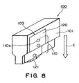
- Figure 8 is a perspective view of the third embodiment of the present invention, the ink outlet of which is sealed with the sealing jacket.
- the ink container 100 shown in Figure 8 has two chambers: an ink storage chamber, and a negative pressure generating member storage chamber filled with a negative pressure generating member.
- the wall of the ink storage chamber has an ink outlet (unshown), the opening of which is filled with a filter (unshown).
- the sealing jacket 103 is formed of film, and is U-shaped. This embodiment of an ink container 100 is relatively flat, and the sealing jacket 103 covers the ink container 100 across the three surfaces: the surface with the ink outlet 102, and the largest pair of surfaces sandwiching the surface having the ink outlet 102 (surfaces contiguous to surface with ink outlet). Each of the largest pairs of surfaces has a step.
- the direction in which the sealing jacket 103 is placed on the ink container proper 101 does not need to be limited to the direction in which the sealing jacket 103 of this embodiment is placed; for example, the sealing jacket 103 may be placed across the surface with the ink outlet, and the pair of surfaces contiguous to the surface with the ink outlet, other than the largest pair of surfaces.
- the sealing jacket 103 has first and second adherent portions 110 and 111, which are positioned so that as the sealing jacket 103 is placed on the ink container 100, they will be on the pair (largest pair) of the surfaces of the ink container proper 101 contiguous to the surface of the ink container proper 101 with the ink outlet 102.
- the first adherent portion 110, and the second adherent portion 111 which opposes across the ink container proper 101, are spot-welded to the corresponding surfaces of the ink container proper 101.
- the method for unsealing the ink outlets 102 is the same as the method for unsealing the ink outlet of the first and second embodiments of the present invention; the sealing jacket 103 is to be peeled in the direction indicated by an arrow mark E in Figure 8 .
- the sealing jacket 103 is to be peeled in the following manner. Referring to Figure 8 , first, the adherent portion 110 is to be pulled in the direction indicated by the arrow mark E. A user should know that the sealing jacket 103 should be gradually peeled, instead of abruptly, because the first adherent portion 110 is spot-welded to the surface of the ink container proper 101 at plural spots 110a in a straight line in the lengthwise direction of the sealing jacket 103. As the user gradually peels the first adherent portion 110, the user can realize the proper amount of force (stress) necessary to peel the sealing jacket 103, being enabled to refrain from applying an excessive amount of force which will result in the abrupt peeling the sealing jacket 103.
- stress stress
- the peeling of the first adherent portion 110 ends.
- the adhesive strength, between the first adherent portion and the corresponding surface of the ink container proper 101, against which force is applied to the sealing jacket 103 to peel the sealing jacket 103 becomes zero.
- the hand of the user may be suddenly let go in the direction indicated by the arrow mark E due to the loss of resistance, at the same time as the peeling of the first adherent portion 110 ends.
- This problem that the hand of the user grasping the sealing jacket 103 is suddenly let go in the arrow direction can be avoided by setting the adhesive strength between the first adherent portion 110 and the corresponding wall of the ink container proper 101 to a level at which an excessive amount of force is not necessary to peel the first adherent portion 110.
- the cap 121 which was kept, by the sealing jacket 103, in the position in which it seals the ink outlet 102, is removed from the ink outlet 102 in a manner to rotate about the welding spot (unshown) of the second adherent portion 111 closest to the ink outlet 102, unsealing the ink outlet 102.
- the welding spot unshown
- the movement of the hand of the user remains well controlled, and therefore, it does not occur that the ink outlet 102 is abruptly unsealed.
- the phenomenon that the ink between the ink outlet 102 and cap 121 is accelerated by the abrupt movement of the sealing jacket 103 caused by the jerky movement of the user's hand, and splashes, instead of remaining adhered to the ink outlet 102 and/or cap 121, does not occur.
- the sudden loss of the resistance coming from the adhesive strength between the first adherent portion 110 and ink container proper 101 makes it possible for the user to sense the completion of the unsealing of the ink outlet 102.
- this embodiment can also prevent the sealing jacket 103 from being jerked at the end of the peeling of the first adherent portion 110 during the unsealing of the ink outlet 102, preventing therefore the phenomenon that the ink between the ink outlet 102 and cap 121 is accelerated by the jerking of the user's hand, and splashes, instead of remaining adhered to the ink outlet 102 and/or cap 121. Further, this embodiment is also capable of preventing the ink on the sealing surface of the cap 121 from splashing.
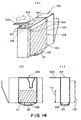
- FIG. 14 the fourth embodiment of the present invention will be described.
- This embodiment of an ink container in accordance with the present invention is similar to the first embodiment, except for the sealing jacket 103 and sealing member 105.
- this embodiment will be described regarding only the sealing jacket 103 and sealing member 105, and the method for unsealing the portions sealed by the sealing jacket 103 and sealing member 105.
- Figure 14(a) is a perspective view of this embodiment
- Figure 14(b) is a side view of this embodiment
- Figure 14(c) is a frontal plan view of this embodiment.
- the sealing jacket 103 of the ink container 100 comprises a wrapping belt portion 120 and a sealing jacket 103 formed of the same materials as the materials for the wrapping belt portion 120 and sealing jacket 103 of the first embodiment. It is wrapped around the ink container proper 101. It is long enough to be extendable a certain length from the ink container proper 101 roughly in parallel to the surface of the ink container proper 101, that is, perpendicular to the pair of the largest surfaces of the ink container proper 101, after being wrapped once around the ink container proper 101. It is formed by cutting a part of the sealing jacket 103 in the form of a tab.
- this sealing jacket 103 is provided with two straight perforations 510, which extend one for one from the two ends (tear start points 510) of the base portions of the tab 500 in such a manner that as the sealing jacket 103 is wrapped around the ink container proper 101, the two perforations reach the virtually the bottom edge (tear stop points 512) of the ink container proper 101.
- the first and second adherent portion 110 and 111 of this embodiment are the same as those of the first embodiment; they are positioned so that as the sealing jacket 103 is wrapped around the ink container proper 101, they will be on the two lateral surfaces (two surfaces contiguous to surface with ink outlet 102) of the ink container proper 101, which oppose each other, sandwiching the surface with the ink outlet 102.
- the sealing member 105 is square and is formed of film. It is adhered to the ink container proper 101 so that it seals the air vent 104.
- the sealing member 105 should be peeled before the ink container 100 is mounted into an ink jet recording apparatus (unshown). Therefore, semipermanent adhesive or thermal welding is used as the means for attaching the sealing jacket 103 to the ink container proper 101.
- the sealing member 105 is attached to the sealing jacket 103 with the use of such an adhesive, or a thermal welding method, that makes the adhesive strength between the sealing member 105 and sealing jacket 103 greater than the force necessary to remove the sealing member 105 from the air vent 104.
- the ink container is to be unsealed in the following manner.
- a user is to grasp the tab 500 of the sealing jacket 103, and pull it to sever the sealing jacket 103, while peeling the sealing jacket 103 in the direction in which the sealing jacket 103 is wrapped around the ink container proper 101.
- the sealing jacket 103 is provided with the two perforations 510 along which the sealing jacket 103 is easily severable.
- the two perforations 510 extend from the two ends (tear start points) of the base portion of the tab 500.
- the sealing jacket 103 will easily tear along the perforations 510, allowing the portion of the sealing jacket 103 between the two perforations to be easily peeled. During this process, the user can assure him/herself, by finding the perforations, that the sealing jacket 103 is being peeled in the correct direction.
- the sealing member 105 begins to be peeled away from the ink container proper 101 along with the sealing jacket 103, exposing the air vent 104. This occurs because the adhesive strength between the sealing member 105 and sealing jacket 103 is greater than that between the sealing member 105 and ink container proper 101, and therefore, the sealing member 105 remains stuck to the sealing jacket 103 as the sealing jacket 103 is peeled.
- the sealing member 105 is glued to the ink container proper 101 firmly enough to keep the air vent 104 sealed.
- the force being applied to the sealing jacket 103 to peel the sealing jacket 103 must be increased. Therefore, unless a certain measure is taken, the hand of the user pulling the tab 500 will be let go jerkingly and uncontrollably, abruptly peeling the portion of the sealing jacket 103 which comes after the sealing member 105, as the same time as the sealing member 105 is completely peeled. In the case of this embodiment, however, there is the first adherent portion 110 close to the ends 512 of the perforations 510, and the first adherent portion 110 functions as the stopper for controlling the jerky movement of the user's hand.
- the first adherent portion 110 can temporarily halt the peeling of the sealing jacket 103 to prevent the following problem. That is, if the ink outlet 102 is unsealed, with the user's hand moving at the same velocity as the velocity at which it began to move due to the sudden reduction in the resistance to the force applied by the user's hand to the tab 500 to peel the portion of the sealing jacket 103 having the sealing member 105, ink will be splashed. With the presence of the first adherent portion 110, the jerky movement of the user's hand is prevented from continuing.
- this unsealing method can be easily carried out by anybody, because all that has to be done is to grasp and pull the tab 500 to peel the sealing jacket 103.
- the employment of the sealing member 105 is not mandatory.
- the air vent 105 may be directly sealed by the sealing jacket 103.
- This ink container 100 is similar to the first and fourth embodiments of the present invention, except that the sealing jacket 103 of this ink container 100 is different from that of the fourth embodiment. Thus, this embodiment will be described regarding only the portion of the unsealing method involving the sealing jacket 103 and the portion of the ink container proper 101 covered with the sealing jacket 103.
- Figure 15(a) is a perspective view of this embodiment of an ink container in accordance with the present invention
- Figure 15(b) a side view of the same
- Figure 15(c) the frontal plan view of the same
- Figure 15(d) is an enlarged view of the cut interval change point, and its adjacencies, of the perforations of this embodiment of a sealing jacket 103.
- the sealing jacket 103 itself will be described.
- the sealing jacket 103 comprises a wrapping belt portion 120 and a cap 121 formed of the same material as those for the first and fourth embodiments. It is similar to the fourth embodiment in shape, inclusive of its tab 500.
- the sealing jacket 103 is provided with a pair of perforations 510, which extend from the ends (starting points of perforation 511) of the base line of the tab 500, in the direction parallel to the direction in which the sealing jacket 103 is wrapped around the ink container proper 101, long enough to reach the adjacencies (ends points of perforations 512) of the bottom edge of the surface of the ink container proper 101 contiguous to the surface of the ink container proper 101 having the air vent 104, extending across the two surfaces.
- Each perforation 510 is has two sections different in the cut interval. The two sections are separated at a cut interval change point 513.
- each cut interval 514 of the section of the perforation between the starting point 511 and cut interval change point is shorter and each cut interval 515 of the rest of the perforation, that is, the section of the perforation between the cut interval change point 513 and tear end point 512. Therefore, the sealing jacket 103 is easier to tear along the former than the latter.
- the sealing member 105 is attached to the portion of the sealing jacket 103 between the two perforations, with the use of such an adhesive, or thermal welding method, that makes the adhesive strength between the sealing member 105 and sealing jacket 103 greater than the adhesive strength between the sealing member 105 and the ink container proper 101 (more specifically, portion which surrounds air vent 104).
- the adherent portion 600 is positioned so that the rear edge of the adherent portion 600, in terms of the direction in which the sealing jacket 103 is to be peeled, approximately coincides with the end point 512 of each perforation.
- the adherent portion 600 is also to be peeled when unsealing the ink container 100, it is glued to the ink container proper 101 with the use of such an adhesive, or thermal welding method, that allows the adherent portion 600 to be easily peeled.
- the ink container 100 is unsealed in the following manner.
- a user is to grasp the tab 500 of the sealing jacket 103 and pull it in the direction parallel to the direction in which the sealing jacket 103 is wrapped around the ink container proper 101; the sealing jacket 103 is peeled by tearing the sealing jacket 103 along the two perforations 510, which extend from the base portion (tear start point 511) of the tab 500.
- the sealing jacket 103 easily tears along the two perforations 510, allowing the portion of the sealing jacket 103 between the two perforations to be easily peeled.
- the user should confirm the presence of the perforations at the points at which the sealing jacket 103 is being torn, because this confirmation assures the user that the sealing jacket 103 is being properly torn.
- the sealing member 105 begins to be peeled from the ink container proper 101 along with the portion of the sealing jacket 103 between the two perforations, exposing the air vent 104. This occurs because the sealing member 105 is adhered to the sealing jacket 103 and ink container proper 101 in such a manner that the adhesive strength between the sealing member 105 and sealing jacket 103 becomes greater than that between the sealing member 105 and ink container proper 101 (more specifically, portion around air vent 104), and therefore, the sealing member 105 remains attached to the sealing jacket 103.
- the amount of force necessary to peel the sealing member 105 from the ink container proper 101 is greater than the amount of force necessary to tear the sealing jacket 103 along the two perforations. Therefore, the user will exert a greater amount of muscular force while peeling the sealing member 105. Then, as soon as the sealing member 105 is completely peeled, the amount of force necessary to peel the sealing jacket 103 suddenly reduces, even through the user is still exerting muscular force by the amount necessary to peel the sealing member 105. Thus, unless a certain measure is taken, the user's hand jerkingly moves while pulling the sealing jacket 103. Consequently, the portion of the sealing jacket 103 between the two perforations after the sealing member 105 will be yanked away.
- each perforation has two sections different in cut interval.
- the cut interval change point 513 which divides the perforation into the two sections different in cut interval, is positioned so that it will be on the surface of the ink container proper 101 contiguous to the surface of the ink container proper 101 having the air vent 104. Therefore, the portion of the sealing jacket 103 corresponding to the cut interval change point 513 functions as the stopper for temporarily halting the unsealing of the ink container 100, preventing therefore the yanking of the sealing jacket 103 resulting from above described the jerky movement of the user's hand.
- the cut intervals 514 in the section of each perforation between the tear start point 511 and cut interval change point 513 are relatively short, making it relatively easy to tear the sealing jacket 103 along the perforation, whereas the cut intervals 515 in the section of the perforation between the cut interval change point 513 and end point 512 are relatively long, increasing the amount of the force necessary to tear the sealing jacket 103 along this section of the perforation.
- the abrupt peeling of the sealing jacket 103 by the above described jerky movement of the user's hand is stopped by the difference in the amount of force necessary to tear the sealing jacket 103 along the perforation between the two sections of the perforation.
- the user After the abrupt tearing of the sealing jacket 103 is stopped by the portion of the sealing jacket 103 having the cut interval change points 513 of the perforations, the user is to start again to peel the portion of the sealing jacket 103 between the two perforations while tearing the sealing jacket 103 along the perforations, to the end points of the perforations 510.
- a relatively larger amount of force is required to tear the sealing jacket 103 along the section of the perforation between the cut interval change point 513 and the end point 512, and this section is made long enough, in terms of the direction in which the sealing jacket 103 is wrapped around the ink container proper 101, to make the user realize that this portion of the sealing jacket 103 should be extra carefully peeled, that is, without yanking.
- the user will accurately sense the amount of force necessary to peel the rest of the sealing jacket 103, being therefore prevented from applying an excessive amount of force; in other words, the user is prevented from jerkingly peeling the remaining portion of the sealing jacket 103.
- the sealing member 103 loses it endless form.
- the resistance to the force applied to the sealing jacket 103 by the user to peel it suddenly disappears, which would have caused the user's hand to jerkingly accelerate in the direction in which the user was pulled the sealing jacket 103.
- the user is not applying an excessive amount of force to the sealing jacket 103. Therefore, even when the resistance disappear, the user's hand does not jerkingly accelerate.
- the ink outlet 102 is to be unsealed.
- a liquid container sealing jacket for sealing the liquid outlet of a liquid container.
- a liquid container sealing jacket is provided with a minimum of two portions (first to fourth embodiments) by which it is attached to the liquid container, or a combination of an adherent portion and a tearing means (fifth embodiment) requiring a predetermined amount of force to tear it, which are independently disposed in a manner to sandwich the liquid outlet of the liquid container in terms of the direction in which the sealing jacket is to be peeled.
- the length of the adherent portion to be peeled first (first to fourth embodiments), or the length of the tearing means (first embodiment), makes it possible for the user to recognize the amount of force necessary to peel the sealing jacket, preventing thereby the sealing jacket from being abruptly peeled away by the application of an excessive amount of force.
- the portion of the sealing jacket corresponding in position to the liquid outlet is not adhered to the surface of the liquid container. Therefore, as soon as the peeling of the first adherent portion of the sealing jacket (first to fourth embodiments), or the tearing means (fifth embodiment), is completed, the liquid outlet can be unsealed. As described above, during this process, it does not occur that the sealing jacket is abruptly peeled. Therefore, the phenomenon that liquid in or around the liquid outlet is splashed does not occur. Further, the liquid outlet becomes open as the amount of force necessary to peel suddenly reduces to zero, giving the user the sense of completion that the liquid outlet has just been unsealed.
- the second adherent portion of the sealing jacket functions as the stopper for temporarily halting the peeling movement of the user, preventing the sealing member from being abruptly peeled in a single quick stroke, preventing therefore the ink adhering to the sealing jacket from being splashed.
- the sealing jacket can be peeled away simply by grasping the tab and pulling it. Therefore, an ink container fitted with the sealing jacked in accordance with the present invention can be easily unsealed by anybody.
Applications Claiming Priority (5)
| Application Number | Priority Date | Filing Date | Title |
|---|---|---|---|
| JP2002074227 | 2002-03-18 | ||
| JP2002074227 | 2002-03-18 | ||
| JP2003036544 | 2003-02-14 | ||
| JP2003036544A JP4250433B2 (ja) | 2002-03-18 | 2003-02-14 | 液体収納容器の包装構造およびその開封方法 |
| EP03005937A EP1346832B1 (en) | 2002-03-18 | 2003-03-17 | Liquid container sealing jacket, and method for unsealing liquid container fitted with liquid container jacket |
Related Parent Applications (1)
| Application Number | Title | Priority Date | Filing Date |
|---|---|---|---|
| EP03005937A Division EP1346832B1 (en) | 2002-03-18 | 2003-03-17 | Liquid container sealing jacket, and method for unsealing liquid container fitted with liquid container jacket |
Publications (3)
| Publication Number | Publication Date |
|---|---|
| EP1598196A2 EP1598196A2 (en) | 2005-11-23 |
| EP1598196A3 EP1598196A3 (en) | 2007-10-03 |
| EP1598196B1 true EP1598196B1 (en) | 2009-11-18 |
Family
ID=27791026
Family Applications (2)
| Application Number | Title | Priority Date | Filing Date |
|---|---|---|---|
| EP05017034A Expired - Lifetime EP1598196B1 (en) | 2002-03-18 | 2003-03-17 | Liquid container comprising a sealing jacket, and method for unsealing liquid container fitted with liquid container jacket |
| EP03005937A Expired - Lifetime EP1346832B1 (en) | 2002-03-18 | 2003-03-17 | Liquid container sealing jacket, and method for unsealing liquid container fitted with liquid container jacket |
Family Applications After (1)
| Application Number | Title | Priority Date | Filing Date |
|---|---|---|---|
| EP03005937A Expired - Lifetime EP1346832B1 (en) | 2002-03-18 | 2003-03-17 | Liquid container sealing jacket, and method for unsealing liquid container fitted with liquid container jacket |
Country Status (7)
| Country | Link |
|---|---|
| US (3) | US7552837B2 (zh) |
| EP (2) | EP1598196B1 (zh) |
| JP (1) | JP4250433B2 (zh) |
| KR (1) | KR20030076320A (zh) |
| CN (1) | CN1217800C (zh) |
| AT (2) | ATE448947T1 (zh) |
| DE (2) | DE60330189D1 (zh) |
Families Citing this family (19)
| Publication number | Priority date | Publication date | Assignee | Title |
|---|---|---|---|---|
| JP4250433B2 (ja) * | 2002-03-18 | 2009-04-08 | キヤノン株式会社 | 液体収納容器の包装構造およびその開封方法 |
| US20070246146A1 (en) * | 2006-04-19 | 2007-10-25 | Lexmark International, Inc. | Perforated and/or pointed sealing film for easy peel inkjet printhead and ink tank system applications |
| US8066360B2 (en) * | 2007-04-18 | 2011-11-29 | Hewlett-Packard Development Company, L.P. | Fluid cartridge for a fluid supply system |
| DE102007055161A1 (de) * | 2007-11-19 | 2009-05-20 | Pelikan Hardcopy Production Ag | Tintenpatrone, insbesondere für einen Tintenstrahldrucker |
| JP5191427B2 (ja) * | 2009-03-24 | 2013-05-08 | 富士フイルム株式会社 | 液体供給用容器 |
| JP5213973B2 (ja) * | 2011-02-18 | 2013-06-19 | 富士フイルム株式会社 | 画像記録用液体カートリッジ及び画像形成装置 |
| US8777060B2 (en) * | 2012-01-16 | 2014-07-15 | Spiroflow Systems, Inc. | Discharger for side-secured bag spout |
| KR102100600B1 (ko) | 2013-09-18 | 2020-04-13 | 캐논 가부시끼가이샤 | 잉크 카트리지 및 잉크젯 프린터 |
| MY181133A (en) | 2013-09-18 | 2020-12-18 | Canon Kk | Ink cartridge and ink jet printer |
| JP6241355B2 (ja) * | 2014-04-07 | 2017-12-06 | セイコーエプソン株式会社 | 液体供給ユニット用の保護部材 |
| JP6700719B2 (ja) | 2015-10-30 | 2020-05-27 | キヤノン株式会社 | 液体吐出装置及びヘッド |
| JP6602160B2 (ja) | 2015-10-30 | 2019-11-06 | キヤノン株式会社 | 液体吐出装置及びヘッド |
| JP2017081083A (ja) | 2015-10-30 | 2017-05-18 | キヤノン株式会社 | 液体吐出装置、ヘッド及び液体充填方法 |
| JP6498098B2 (ja) | 2015-10-30 | 2019-04-10 | キヤノン株式会社 | 記録装置および液体収容部材 |
| US9878554B1 (en) | 2016-10-13 | 2018-01-30 | Funai Electric Co., Ltd. | Packaging system for fluidic ejection cartridge with controlled protective tape removal |
| JP7110038B2 (ja) | 2018-09-06 | 2022-08-01 | キヤノン株式会社 | 液体貯留容器および液体吐出装置 |
| JP7292910B2 (ja) * | 2019-03-19 | 2023-06-19 | キヤノン株式会社 | 液体収納容器、液体吐出ヘッド及び液体吐出装置 |
| JP2021183400A (ja) | 2020-05-22 | 2021-12-02 | キヤノン株式会社 | 液体カートリッジおよび液体吐出装置 |
| JP2022054843A (ja) | 2020-09-28 | 2022-04-07 | キヤノン株式会社 | 液体容器および液体吐出装置 |
Family Cites Families (49)
| Publication number | Priority date | Publication date | Assignee | Title |
|---|---|---|---|---|
| US3325058A (en) * | 1964-03-10 | 1967-06-13 | Jr Junius Mosby West | Electrically heated receptacles and disposable containers therefor |
| US5231416A (en) * | 1988-11-09 | 1993-07-27 | Canon Kabushiki Kaisha | Container for ink jet head and recovering method of ink jet head using container |
| US5430471A (en) * | 1991-08-30 | 1995-07-04 | Canon Kabushiki Kaisha | Liquid container, recording head using same and recording apparatus using same |
| JP3105047B2 (ja) | 1991-11-18 | 2000-10-30 | キヤノン株式会社 | インク容器、これを用いた記録ヘッドユニットおよびこれを搭載する記録装置 |
| ATE179122T1 (de) * | 1992-02-24 | 1999-05-15 | Canon Kk | Ein flüssigkeitsbehälter, eine tintenstrahlpatrone mit einem flüssigkeitsbehälter und ein tintenstrahl- aufzeichnungsgerät mit derartiger patrone |
| US6332675B1 (en) | 1992-07-24 | 2001-12-25 | Canon Kabushiki Kaisha | Ink container, ink and ink jet recording apparatus using ink container |
| US6170939B1 (en) | 1992-07-31 | 2001-01-09 | Canon Kabushiki Kaisha | Liquid storing container for recording apparatus |
| CA2272160C (en) | 1992-07-31 | 2003-10-14 | Canon Kabushiki Kaisha | Liquid storing container for recording apparatus |
| US5525475A (en) * | 1992-08-12 | 1996-06-11 | Ladouceur; Cynthia A. | Diffusion through a membrane assaying apparatus and method |
| JP3165281B2 (ja) * | 1993-05-25 | 2001-05-14 | キヤノン株式会社 | 交換型インクジェット記録用インクカートリッジのパッケージおよびその開封方法 |
| EP0627317B1 (en) | 1993-05-25 | 1998-08-12 | Canon Kabushiki Kaisha | Packing case and opening method therefor |
| EP0635373B1 (en) | 1993-07-20 | 1998-03-11 | Canon Kabushiki Kaisha | Ink jet recording apparatus using recording unit with ink cartridge having ink inducing element |
| US5356029A (en) * | 1993-08-25 | 1994-10-18 | Kaneka Texas Corporation | Bin-type bulk fluid container |
| EP0685340B1 (en) * | 1994-05-31 | 1999-08-18 | Canon Kabushiki Kaisha | Replaceable ink cartridge and seal structure thereof |
| JP3168116B2 (ja) * | 1994-05-31 | 2001-05-21 | キヤノン株式会社 | 交換型インクカートリッジ |
| USD378660S (en) * | 1995-01-30 | 1997-04-01 | Tohoku Ricoh Co., Ltd. | Container for liquid ink for a printing machine |
| JP3227388B2 (ja) | 1995-08-02 | 2001-11-12 | キヤノン株式会社 | インク吸収体、該インク吸収体を用いたインクタンク、該インクタンクとインクジェット記録ヘッドとを一体化したインクジェットカートリッジ、インクタンクの製造方法、及び該インクタンクに用いられる繊維塊 |
| JP3327807B2 (ja) * | 1996-03-01 | 2002-09-24 | キヤノン株式会社 | インクタンクの包装構造および該包装構造が施されるインクタンク |
| JP3720586B2 (ja) | 1997-07-30 | 2005-11-30 | キヤノン株式会社 | インクタンク、該インクタンクに用いられるインク吸収体、及びインクタンクの製造方法 |
| US6146769A (en) * | 1997-12-31 | 2000-11-14 | E. I. Du Pont De Nemours And Company | Ink/textile combination having improved durability |
| JP3669179B2 (ja) | 1998-10-15 | 2005-07-06 | セイコーエプソン株式会社 | インクカートリッジ装置 |
| JP3667127B2 (ja) | 1998-12-24 | 2005-07-06 | キヤノン株式会社 | 液体供給システムの液体残量検出方法 |
| JP2001063090A (ja) | 1999-04-27 | 2001-03-13 | Canon Inc | インクタンク、該インクタンクに用いられる弁ユニット、前記インクタンクの製造方法、前記インクタンクを備えたインクジェットヘッドカートリッジおよびインクジェット記録装置 |
| JP2000309105A (ja) | 1999-04-27 | 2000-11-07 | Canon Inc | 液体収納容器、液体供給システムおよび前記液体収納容器の製造方法 |
| JP2001063098A (ja) | 1999-04-27 | 2001-03-13 | Canon Inc | 液体収納容器、該液体収納容器に用いられる弁機構および液体供給容器 |
| JP2001010078A (ja) | 1999-04-27 | 2001-01-16 | Canon Inc | インクタンク、該インクタンクが取り付けられるホルダー、該ホルダーを備えたインクジェット記録装置、インクタンクのホルダーへの装着方法 |
| JP2001063097A (ja) | 1999-04-27 | 2001-03-13 | Canon Inc | 液体供給システム及び該システムに用いられる液体供給容器 |
| JP3450798B2 (ja) | 1999-04-27 | 2003-09-29 | キヤノン株式会社 | 液体供給システム、該システムに用いられる液体収納容器、該システムを用いたインクジェットヘッドカートリッジ |
| US6443567B1 (en) | 1999-04-27 | 2002-09-03 | Canon Kabushiki Kaisha | Liquid ejecting cartridge and recording device using same |
| JP2001063099A (ja) | 1999-06-23 | 2001-03-13 | Canon Inc | インクタンク、インクタンクを搭載するインクジェット記録装置、およびインクタンクの包装パッケージ |
| JP2001001544A (ja) | 1999-06-24 | 2001-01-09 | Canon Inc | 液体供給方法、液体供給容器、負圧発生部材収納容器及び液体収納容器 |
| US6505923B1 (en) | 1999-06-24 | 2003-01-14 | Canon Kabushiki Kaisha | Liquid supply system, liquid supply container and negative pressure generating member container used for the same system, and ink jet recording apparatus using the same system |
| US6450631B1 (en) | 1999-06-24 | 2002-09-17 | Canon Kabushiki Kaisha | Storing method of ink tank and ink jet head cartridge, and ink tank and storing container used in the same method |
| JP2001001546A (ja) | 1999-06-24 | 2001-01-09 | Canon Inc | 液体供給システム及び該システムに用いられる液体供給容器 |
| JP2001001542A (ja) | 1999-06-24 | 2001-01-09 | Canon Inc | 液体供給方法および該液体供給方法に用いられる毛管力発生部材収納容器および液体供給容器 |
| US6471343B1 (en) | 1999-06-24 | 2002-10-29 | Canon Kabushiki Kaisha | Ink supply system and ink jet recording apparatus |
| JP4282043B2 (ja) | 1999-12-06 | 2009-06-17 | キヤノン株式会社 | 記録液体供給通路、記録液体収納容器、およびこれらを備える記録液体供給装置、並びにその表面改質方法 |
| CA2327067A1 (en) | 1999-12-06 | 2001-06-06 | Canon Kabushiki Kaisha | Surface reformed fiber body, liquid container using fiber absorber, and method of producing fiber absorber for use in liquid ejection |
| JP4789315B2 (ja) | 2000-10-04 | 2011-10-12 | キヤノン株式会社 | インクタンクモジュールおよびインクジェット記録装置 |
| US6540342B2 (en) | 2000-10-05 | 2003-04-01 | Canon Kabushiki Kaisha | Liquid container and method for disconnecting liquid container |
| JP4521981B2 (ja) | 2000-11-09 | 2010-08-11 | キヤノン株式会社 | 繊維集合体の製造方法 |
| JP3796439B2 (ja) | 2001-02-09 | 2006-07-12 | キヤノン株式会社 | 液体収納容器 |
| JP3697213B2 (ja) | 2001-02-09 | 2005-09-21 | キヤノン株式会社 | 液体収納容器、および液体の撹拌方法 |
| CA2371040A1 (en) | 2001-02-09 | 2002-08-09 | Nobuyuki Hatasa | Liquid container and recording apparatus |
| JP3774675B2 (ja) | 2001-05-10 | 2006-05-17 | キヤノン株式会社 | パッケージ |
| JP2003103797A (ja) | 2001-09-28 | 2003-04-09 | Canon Inc | 液体収納容器、液体収納容器の接続ユニット、並びにインクジェット記録装置 |
| JP3667283B2 (ja) | 2002-01-25 | 2005-07-06 | キヤノン株式会社 | 液体収納容器 |
| JP4250433B2 (ja) * | 2002-03-18 | 2009-04-08 | キヤノン株式会社 | 液体収納容器の包装構造およびその開封方法 |
| JP3919567B2 (ja) | 2002-03-18 | 2007-05-30 | キヤノン株式会社 | 液体収納容器の包装構造およびその開封方法 |
-
2003
- 2003-02-14 JP JP2003036544A patent/JP4250433B2/ja not_active Expired - Fee Related
- 2003-03-17 EP EP05017034A patent/EP1598196B1/en not_active Expired - Lifetime
- 2003-03-17 DE DE60330189T patent/DE60330189D1/de not_active Expired - Lifetime
- 2003-03-17 AT AT05017034T patent/ATE448947T1/de not_active IP Right Cessation
- 2003-03-17 EP EP03005937A patent/EP1346832B1/en not_active Expired - Lifetime
- 2003-03-17 DE DE60312912T patent/DE60312912T2/de not_active Expired - Lifetime
- 2003-03-17 US US10/388,393 patent/US7552837B2/en not_active Expired - Fee Related
- 2003-03-17 AT AT03005937T patent/ATE358587T1/de not_active IP Right Cessation
- 2003-03-18 KR KR10-2003-0016680A patent/KR20030076320A/ko not_active IP Right Cessation
- 2003-03-18 CN CN031207383A patent/CN1217800C/zh not_active Expired - Fee Related
-
2005
- 2005-07-18 US US11/182,787 patent/US7207159B2/en not_active Expired - Fee Related
- 2005-07-18 US US11/182,807 patent/US7303090B2/en not_active Expired - Lifetime
Also Published As
| Publication number | Publication date |
|---|---|
| DE60312912D1 (de) | 2007-05-16 |
| ATE358587T1 (de) | 2007-04-15 |
| US7303090B2 (en) | 2007-12-04 |
| US20050257505A1 (en) | 2005-11-24 |
| EP1346832A2 (en) | 2003-09-24 |
| EP1346832B1 (en) | 2007-04-04 |
| DE60330189D1 (de) | 2009-12-31 |
| JP2003341089A (ja) | 2003-12-03 |
| US20050257506A1 (en) | 2005-11-24 |
| ATE448947T1 (de) | 2009-12-15 |
| EP1346832A3 (en) | 2004-04-28 |
| US20040003577A1 (en) | 2004-01-08 |
| EP1598196A2 (en) | 2005-11-23 |
| US7207159B2 (en) | 2007-04-24 |
| CN1217800C (zh) | 2005-09-07 |
| DE60312912T2 (de) | 2007-12-13 |
| KR20030076320A (ko) | 2003-09-26 |
| JP4250433B2 (ja) | 2009-04-08 |
| US7552837B2 (en) | 2009-06-30 |
| CN1445093A (zh) | 2003-10-01 |
| EP1598196A3 (en) | 2007-10-03 |
Similar Documents
| Publication | Publication Date | Title |
|---|---|---|
| US7303090B2 (en) | Liquid container sealing jacket, and method for unsealing liquid container fitted with liquid container jacket | |
| EP0627317B1 (en) | Packing case and opening method therefor | |
| US6276786B1 (en) | Packaging structure for ink tank and ink tank packaged in such packaging structure | |
| EP0729835B1 (en) | Member and method for protecting ink tank | |
| JP4988239B2 (ja) | 密封可撓性コンテナーの開放用器具 | |
| US6942325B2 (en) | Packaging structure for liquid container and unsealing method therefor | |
| US6283587B1 (en) | Printer ink cartridge and ink cartridge device including the same | |
| JPH08258864A (ja) | バッグインカートンおよびカートンブランク体 | |
| US20070189835A1 (en) | Packaging comprising an applicator for applying liquid and pasty media | |
| US5729797A (en) | Toner cartridge | |
| JP3804914B2 (ja) | 接着剤等の充填容器 | |
| US6764170B2 (en) | Removable label for sealing an ink-jet ink reservoir | |
| US7008133B2 (en) | Disposable single-use applicator | |
| CN100406262C (zh) | 液体容器 | |
| JPH1058697A (ja) | プリンタのインクカートリッジ装置 | |
| JPH07137277A (ja) | インク収容体の包装部材 | |
| JP2001088879A (ja) | エアゾール容器のガス抜きキャップ | |
| JP2018052505A (ja) | インク補給容器 | |
| CN112875030A (zh) | 墨水补给容器套件、墨水补给容器及其捆包体 | |
| JPH08217179A (ja) | テープカートリッジのフィルム包装体 | |
| JP3607361B2 (ja) | バッグインカートン | |
| JPH08324637A (ja) | バッグインカートン | |
| JP2000255625A (ja) | インクジェット記録用インクカートリッジの包装方法 | |
| JPH08217144A (ja) | バッグインカートン | |
| JPH03118570A (ja) | 貯蔵容器 |
Legal Events
| Date | Code | Title | Description |
|---|---|---|---|
| PUAI | Public reference made under article 153(3) epc to a published international application that has entered the european phase |
Free format text: ORIGINAL CODE: 0009012 |
|
| AC | Divisional application: reference to earlier application |
Ref document number: 1346832 Country of ref document: EP Kind code of ref document: P |
|
| AK | Designated contracting states |
Kind code of ref document: A2 Designated state(s): AT BE BG CH CY CZ DE DK EE ES FI FR GB GR HU IE IT LI LU MC NL PT RO SE SI SK TR |
|
| AX | Request for extension of the european patent |
Extension state: AL LT LV MK |
|
| PUAL | Search report despatched |
Free format text: ORIGINAL CODE: 0009013 |
|
| AK | Designated contracting states |
Kind code of ref document: A3 Designated state(s): AT BE BG CH CY CZ DE DK EE ES FI FR GB GR HU IE IT LI LU MC NL PT RO SE SI SK TR |
|
| AX | Request for extension of the european patent |
Extension state: AL LT LV MK |
|
| 17P | Request for examination filed |
Effective date: 20051017 |
|
| AKX | Designation fees paid |
Designated state(s): AT BE BG CH CY CZ DE DK EE ES FI FR GB GR HU IE IT LI LU MC NL PT RO SE SI SK TR |
|
| 17Q | First examination report despatched |
Effective date: 20080603 |
|
| GRAP | Despatch of communication of intention to grant a patent |
Free format text: ORIGINAL CODE: EPIDOSNIGR1 |
|
| GRAS | Grant fee paid |
Free format text: ORIGINAL CODE: EPIDOSNIGR3 |
|
| GRAA | (expected) grant |
Free format text: ORIGINAL CODE: 0009210 |
|
| AC | Divisional application: reference to earlier application |
Ref document number: 1346832 Country of ref document: EP Kind code of ref document: P |
|
| AK | Designated contracting states |
Kind code of ref document: B1 Designated state(s): AT BE BG CH CY CZ DE DK EE ES FI FR GB GR HU IE IT LI LU MC NL PT RO SE SI SK TR |
|
| REG | Reference to a national code |
Ref country code: GB Ref legal event code: FG4D |
|
| REG | Reference to a national code |
Ref country code: CH Ref legal event code: EP |
|
| REG | Reference to a national code |
Ref country code: IE Ref legal event code: FG4D |
|
| REF | Corresponds to: |
Ref document number: 60330189 Country of ref document: DE Date of ref document: 20091231 Kind code of ref document: P |
|
| REG | Reference to a national code |
Ref country code: NL Ref legal event code: VDEP Effective date: 20091118 |
|
| PG25 | Lapsed in a contracting state [announced via postgrant information from national office to epo] |
Ref country code: FI Free format text: LAPSE BECAUSE OF FAILURE TO SUBMIT A TRANSLATION OF THE DESCRIPTION OR TO PAY THE FEE WITHIN THE PRESCRIBED TIME-LIMIT Effective date: 20091118 Ref country code: PT Free format text: LAPSE BECAUSE OF FAILURE TO SUBMIT A TRANSLATION OF THE DESCRIPTION OR TO PAY THE FEE WITHIN THE PRESCRIBED TIME-LIMIT Effective date: 20100318 Ref country code: ES Free format text: LAPSE BECAUSE OF FAILURE TO SUBMIT A TRANSLATION OF THE DESCRIPTION OR TO PAY THE FEE WITHIN THE PRESCRIBED TIME-LIMIT Effective date: 20100228 Ref country code: SE Free format text: LAPSE BECAUSE OF FAILURE TO SUBMIT A TRANSLATION OF THE DESCRIPTION OR TO PAY THE FEE WITHIN THE PRESCRIBED TIME-LIMIT Effective date: 20091118 |
|
| PG25 | Lapsed in a contracting state [announced via postgrant information from national office to epo] |
Ref country code: CY Free format text: LAPSE BECAUSE OF FAILURE TO SUBMIT A TRANSLATION OF THE DESCRIPTION OR TO PAY THE FEE WITHIN THE PRESCRIBED TIME-LIMIT Effective date: 20091118 Ref country code: SI Free format text: LAPSE BECAUSE OF FAILURE TO SUBMIT A TRANSLATION OF THE DESCRIPTION OR TO PAY THE FEE WITHIN THE PRESCRIBED TIME-LIMIT Effective date: 20091118 |
|
| PG25 | Lapsed in a contracting state [announced via postgrant information from national office to epo] |
Ref country code: BE Free format text: LAPSE BECAUSE OF FAILURE TO SUBMIT A TRANSLATION OF THE DESCRIPTION OR TO PAY THE FEE WITHIN THE PRESCRIBED TIME-LIMIT Effective date: 20091118 Ref country code: AT Free format text: LAPSE BECAUSE OF FAILURE TO SUBMIT A TRANSLATION OF THE DESCRIPTION OR TO PAY THE FEE WITHIN THE PRESCRIBED TIME-LIMIT Effective date: 20091118 |
|
| PG25 | Lapsed in a contracting state [announced via postgrant information from national office to epo] |
Ref country code: DK Free format text: LAPSE BECAUSE OF FAILURE TO SUBMIT A TRANSLATION OF THE DESCRIPTION OR TO PAY THE FEE WITHIN THE PRESCRIBED TIME-LIMIT Effective date: 20091118 Ref country code: BG Free format text: LAPSE BECAUSE OF FAILURE TO SUBMIT A TRANSLATION OF THE DESCRIPTION OR TO PAY THE FEE WITHIN THE PRESCRIBED TIME-LIMIT Effective date: 20100218 Ref country code: EE Free format text: LAPSE BECAUSE OF FAILURE TO SUBMIT A TRANSLATION OF THE DESCRIPTION OR TO PAY THE FEE WITHIN THE PRESCRIBED TIME-LIMIT Effective date: 20091118 Ref country code: RO Free format text: LAPSE BECAUSE OF FAILURE TO SUBMIT A TRANSLATION OF THE DESCRIPTION OR TO PAY THE FEE WITHIN THE PRESCRIBED TIME-LIMIT Effective date: 20091118 Ref country code: NL Free format text: LAPSE BECAUSE OF FAILURE TO SUBMIT A TRANSLATION OF THE DESCRIPTION OR TO PAY THE FEE WITHIN THE PRESCRIBED TIME-LIMIT Effective date: 20091118 |
|
| PG25 | Lapsed in a contracting state [announced via postgrant information from national office to epo] |
Ref country code: CZ Free format text: LAPSE BECAUSE OF FAILURE TO SUBMIT A TRANSLATION OF THE DESCRIPTION OR TO PAY THE FEE WITHIN THE PRESCRIBED TIME-LIMIT Effective date: 20091118 Ref country code: SK Free format text: LAPSE BECAUSE OF FAILURE TO SUBMIT A TRANSLATION OF THE DESCRIPTION OR TO PAY THE FEE WITHIN THE PRESCRIBED TIME-LIMIT Effective date: 20091118 |
|
| PLBE | No opposition filed within time limit |
Free format text: ORIGINAL CODE: 0009261 |
|
| STAA | Information on the status of an ep patent application or granted ep patent |
Free format text: STATUS: NO OPPOSITION FILED WITHIN TIME LIMIT |
|
| 26N | No opposition filed |
Effective date: 20100819 |
|
| PG25 | Lapsed in a contracting state [announced via postgrant information from national office to epo] |
Ref country code: GR Free format text: LAPSE BECAUSE OF FAILURE TO SUBMIT A TRANSLATION OF THE DESCRIPTION OR TO PAY THE FEE WITHIN THE PRESCRIBED TIME-LIMIT Effective date: 20100219 Ref country code: MC Free format text: LAPSE BECAUSE OF NON-PAYMENT OF DUE FEES Effective date: 20100331 |
|
| REG | Reference to a national code |
Ref country code: CH Ref legal event code: PL |
|
| PG25 | Lapsed in a contracting state [announced via postgrant information from national office to epo] |
Ref country code: IE Free format text: LAPSE BECAUSE OF NON-PAYMENT OF DUE FEES Effective date: 20100317 |
|
| PG25 | Lapsed in a contracting state [announced via postgrant information from national office to epo] |
Ref country code: CH Free format text: LAPSE BECAUSE OF NON-PAYMENT OF DUE FEES Effective date: 20100331 Ref country code: LI Free format text: LAPSE BECAUSE OF NON-PAYMENT OF DUE FEES Effective date: 20100331 |
|
| PG25 | Lapsed in a contracting state [announced via postgrant information from national office to epo] |
Ref country code: LU Free format text: LAPSE BECAUSE OF NON-PAYMENT OF DUE FEES Effective date: 20100317 Ref country code: HU Free format text: LAPSE BECAUSE OF FAILURE TO SUBMIT A TRANSLATION OF THE DESCRIPTION OR TO PAY THE FEE WITHIN THE PRESCRIBED TIME-LIMIT Effective date: 20100519 |
|
| PG25 | Lapsed in a contracting state [announced via postgrant information from national office to epo] |
Ref country code: TR Free format text: LAPSE BECAUSE OF FAILURE TO SUBMIT A TRANSLATION OF THE DESCRIPTION OR TO PAY THE FEE WITHIN THE PRESCRIBED TIME-LIMIT Effective date: 20091118 |
|
| PGFP | Annual fee paid to national office [announced via postgrant information from national office to epo] |
Ref country code: IT Payment date: 20140304 Year of fee payment: 12 |
|
| PGFP | Annual fee paid to national office [announced via postgrant information from national office to epo] |
Ref country code: FR Payment date: 20140326 Year of fee payment: 12 |
|
| PG25 | Lapsed in a contracting state [announced via postgrant information from national office to epo] |
Ref country code: IT Free format text: LAPSE BECAUSE OF NON-PAYMENT OF DUE FEES Effective date: 20150317 |
|
| REG | Reference to a national code |
Ref country code: FR Ref legal event code: ST Effective date: 20151130 |
|
| PG25 | Lapsed in a contracting state [announced via postgrant information from national office to epo] |
Ref country code: FR Free format text: LAPSE BECAUSE OF NON-PAYMENT OF DUE FEES Effective date: 20150331 |
|
| PGFP | Annual fee paid to national office [announced via postgrant information from national office to epo] |
Ref country code: GB Payment date: 20180329 Year of fee payment: 16 |
|
| PGFP | Annual fee paid to national office [announced via postgrant information from national office to epo] |
Ref country code: DE Payment date: 20180530 Year of fee payment: 16 |
|
| REG | Reference to a national code |
Ref country code: DE Ref legal event code: R119 Ref document number: 60330189 Country of ref document: DE |
|
| GBPC | Gb: european patent ceased through non-payment of renewal fee |
Effective date: 20190317 |
|
| PG25 | Lapsed in a contracting state [announced via postgrant information from national office to epo] |
Ref country code: DE Free format text: LAPSE BECAUSE OF NON-PAYMENT OF DUE FEES Effective date: 20191001 Ref country code: GB Free format text: LAPSE BECAUSE OF NON-PAYMENT OF DUE FEES Effective date: 20190317 |