EP1594017A2 - Commande à boucle fermée pour la pression dans l'interstice d'un système de fixage par fusion - Google Patents
Commande à boucle fermée pour la pression dans l'interstice d'un système de fixage par fusion Download PDFInfo
- Publication number
- EP1594017A2 EP1594017A2 EP05102509A EP05102509A EP1594017A2 EP 1594017 A2 EP1594017 A2 EP 1594017A2 EP 05102509 A EP05102509 A EP 05102509A EP 05102509 A EP05102509 A EP 05102509A EP 1594017 A2 EP1594017 A2 EP 1594017A2
- Authority
- EP
- European Patent Office
- Prior art keywords
- fuser
- nip
- pressure
- nip width
- uniformity
- Prior art date
- Legal status (The legal status is an assumption and is not a legal conclusion. Google has not performed a legal analysis and makes no representation as to the accuracy of the status listed.)
- Granted
Links
Images

Classifications
-
- G—PHYSICS
- G03—PHOTOGRAPHY; CINEMATOGRAPHY; ANALOGOUS TECHNIQUES USING WAVES OTHER THAN OPTICAL WAVES; ELECTROGRAPHY; HOLOGRAPHY
- G03G—ELECTROGRAPHY; ELECTROPHOTOGRAPHY; MAGNETOGRAPHY
- G03G15/00—Apparatus for electrographic processes using a charge pattern
- G03G15/20—Apparatus for electrographic processes using a charge pattern for fixing, e.g. by using heat
- G03G15/2003—Apparatus for electrographic processes using a charge pattern for fixing, e.g. by using heat using heat
- G03G15/2014—Apparatus for electrographic processes using a charge pattern for fixing, e.g. by using heat using heat using contact heat
- G03G15/2064—Apparatus for electrographic processes using a charge pattern for fixing, e.g. by using heat using heat using contact heat combined with pressure
Definitions
- This invention relates to a fuser system that includes a closed loop control that controls a fuser's nip pressure.
- a latent electrostatic image is formed on a charge-retentive surface, i.e., a photoconductor or photoreceptor.
- a charge-retentive surface i.e., a photoconductor or photoreceptor.
- the surface is first provided with a uniform charge after which it is exposed to a light or other appropriate image of an original document to be reproduced.
- the latent electrostatic image thus formed is subsequently rendered visible by applying any one of numerous toners specifically designed for this purpose.
- the latent electrostatic image may be formed by means other than by the exposure of an electrostatically charged photosensitive member to a light image of an original document.
- the latent electrostatic image may be generated from information electronically stored or generated, and this information in digital form may be converted to alphanumeric images by image generation electronics and optics.
- the particular method by which the image is formed is not critical to the present invention, and any such suitable method may be used.
- the toner image formed is transferred to an image receiving substrate, such as paper. After transfer to the image receiving substrate, the image is made to adhere to the substrate using a fuser apparatus.
- image receiving substrate such as paper
- the image is made to adhere to the substrate using a fuser apparatus.
- the fuser system is set to be within certain specifications for, e.g., dwell time (nip width/process speed), paper velocity and creep. Dwell time is one of the more significant drivers of image fix and quality. Paper velocity is an important factor in paper handling. Creep, which is the release surface's extension in the nip, is important with respect to enabling self-stripping of the paper from the fuser roll. These specifications are set by, for example, setting a roll rotation speed for the paper velocity and setting the nip width for the dwell time and creep.
- the nip width and nip uniformity of a typical fuser is not changed during operation of the xerographic device.
- the fuser system may begin operating outside of specifications due to, e.g., hardening of the roll materials over time.
- Typical fuser roll systems include some materials such as silicone materials that tend to become harder over time at unpredictable rates. This hardening causes large reductions in both dwell time and creep, which causes premature failure (e.g., smaller nip widths that lead to insufficient fixing of the toner image and/or poor image quality, as well as to poor stripping of the image receiving substrate).
- the nip width and nip uniformity in a fuser be altered on demand.
- the fusing quality on thick paper is improved with large nip widths
- the fusing quality on thin papers is often improved with small nip widths.
- Maintaining nip width uniformity is as critical as maintaining the average nip width, as a nip width uniformity out of specification results in two major failure modes. The first is that the axial variation of nip width and pressure results in axial variation of toner adhesion/fix and axial variation of toner gloss, which can cause the fuser to fail to meet print-quality requirements. The second is that the axial nip uniformity also controls the fuser's paper handling and wrinkling performance, so variations in uniformity can cause the fuser to fail for wrinkling, mis-stripping, or other paper-handling reasons.
- a fuser system of a xerographic device including a fuser member and a pressure member in which the pressure member is made to exert pressure upon the fuser member so as to form a nip having a nip width between the fuser member and the pressure member, wherein the nip width is set to within a specification nip width range, a drive system for driving said fuser member relative to said pressure roll; a sensor for monitoring the torque of said drive system; a processor in communication with the sensor that receives torque data from the sensor, wherein the processor determines a current nip pressure uniformity from the torque data and compares the current nip pressure uniformity to the specification nip pressure uniformity range, and a nip pressure adjustment device in communication with the processor, which adjusts the current nip pressure uniformity to be within the specification nip pressure uniformity range.
- the method further comprises repeating said adjusting until both said current nip width uniformity is within the specification nip width uniformity range and said current nip width is within the specification nip width range.
- the adjusting comprises increasing the pressure exerted by the pressure member upon the fuser member.
- the adjusting comprises adjusting load on each end the pressure member upon the fuser member independently.
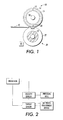
- Figure 1 illustrates a set of a fuser roll and a pressure roll for a xerographic device.
- Figure 2 illustrates the cooperative relationship between a sensor, pressure roll, processor and nip width adjustment device.
- Figure 3 illustrates a mounting structure for a pressure roll in which the pressure exerted upon the fuser member is adjustable with a cam and cam follower.
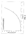
- Figure 4 illustrates data and model estimates for the drive torque required to run a fuser at a variety of fusing nip widths.
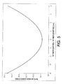
- Figure 5 illustrates predicted torque required to drive a fuser roll/pressure roll nip for a variety of non-uniform nip conditions.
- a typical xerographic machine includes at least a toner image forming station, a transfer station to transfer the toner image to an image receiving substrate, and a fuser system to fix the toner image to the image receiving substrate.
- a latent image of an original image is developed, typically on the surface of a photoconductor or photoreceptor, using a suitable toner material.
- the developed toner image is then transferred to an image receiving substrate such as paper, a transparency, etc., at a transfer station.
- the toner image must then be fixed to the image receiving substrate, which is done by a fuser system that applies heat and pressure to the substrate having the toner image thereon.
- a fuser system of the present invention is comprised of a fuser member that may be comprised of, for example, a fuser roll, or a fuser belt traveling around one or more (fuser) rolls.
- the term "fuser member” as used herein collectively refers to any configuration of a fuser used to contact the toner image in fixing the toner image to the image receiving substrate.
- the fuser system of the present invention is comprised of a pressure member that may be comprised of, for example, a pressure roll, or a pressure belt traveling around one or more rolls.
- pressure member as used herein collectively refers to any member loaded against the fuser member and used to apply pressure to the image and media passed between the fuser member and pressure member.
- the fuser system preferably comprises a set of at least one pair of a fuser member, preferably a fuser roll, and a pressure member, preferably a roll.
- a fuser system may include one or more sets of fuser and pressure rolls, as appropriate.
- a system employing two sets of fuser and pressure rolls is described in U.S. Patent No. 5,436,711, incorporated herein by reference.
- the present invention is described with respect to one set of fuser and pressure rolls in a roll only (non-belt) fuser system.
- the pressure roll 20 is brought to exert pressure upon fuser roll 10, thereby forming a nip 30 having a nip width "a" between the pressure roll and fuser roll.
- An image receiving substrate 40 having a toner image thereon is made to pass through the nip such that the toner image contacts the fuser roll surface.
- the toner image is fixed to the image receiving substrate via heat and pressure.
- the image receiving substrate is stripped from the fuser roll.
- the stripping is a self-stripping, although stripping fingers or other stripping devices may also be used to assist in the stripping as is well known in the art.
- the fuser member of the present invention may have any construction and design, without limitation.
- the invention as it relates to controlling nip width and uniformity velocity over life is most applicable to fuser members having one or more layers thereof comprised of a material that has a tendency to harden or soften over time.
- such materials may include silicone materials, and thus the invention is most applicable to fuser members comprised of one or more layers of a silicone material.
- the fuser member is a fuser roll that includes at least one layer including a silicone material.
- the fuser roll 10 preferably includes an outer layer 15 and an optional intermediate layer 14 upon suitable base member 12 which may be either a solid or hollow cylinder or core fabricated from any suitable metal such as aluminum, anodized aluminum, steel, nickel, copper, and the like. Hollow cylinders or cores are preferred as such can be heated from inside the cylinder or core.
- a suitable heating element 18 may be disposed in the hollow portion of the cylinder or core.
- any suitable external heating option may also be used.
- the outer layer 15 of the fuser member is preferably comprised of a fluoroelastomer, as conventional in the art.
- the fluoroelastomer may include a silicone material therein.
- Suitable fluoroelastomers include FFKM elastomers and hydrofluoroelastomers.
- Illustrative FFKM elastomers are perfluororubbers of the polymethylene type having all substituent groups on the polymer chain either fluoro, perfluoroalkyl, or perfluoroalkoxy groups.
- the hydrofluoroelastomers also known as FKM elastomers
- FKM elastomers are those defined in ASTM designation D1418-90 and are directed to fluororubbers of the polymethylene type having substituent fluoro and perfluoroalkyl or perfluoroalkoxy groups on a polymer chain.
- the fluoroelastomers may be those described in detail in U.S. Patent Nos. 4,257,699, 5,017,432 and 5,061,965. As described therein, these fluoroelastomers, particularly from the class of copolymers, terpolymers and tetrapolymers of vinylidenefluoride hexafluoropropylene, tetrafluoroethylene, and a cure site monomer (believed to contain bromine), are known commercially under various designations as the VITONTM line of fluoroelastomers available from E.I. DuPont de Nemours, Inc. Other commercially available materials include the FLUORELTM line of fluoroelastomers available from 3M Company.
- Additional commercially available materials include AFLASTM a poly(propylene-tetrafluoroethylene) copolymer, FLUOREL IITM a poly(propylene-tetrafluoroethylene-vinylidenefluoride) terpolymer both also available from 3M Company.
- Fillers for example alumina fillers, heat stabilizers, etc., may be included in the outer layer, as well known in the art. See, for example, U.S. Patents Nos. 4,711,818 and 5,729,813.
- the outer surface layer of the fuser member preferably has a thickness of from about 1 to about 9 mils.
- One or more optional intermediate layers may be positioned between the substrate and the outer fluoropolymer/silicone layer.
- the intermediate layers preferably comprise a silicone rubber of a thickness so as to form a conformable layer.
- Suitable silicone rubbers include room temperature vulcanization (RTV) silicone rubbers; high temperature vulcanization (HTV) silicone rubbers and low temperature vulcanization (LTV) silicone rubbers. These rubbers are known and readily available commercially such as the SILASTICTM line from Dow Coming and the RTV Silicone Rubber line from General Electric.
- an intermediate layer preferably has a thickness of from about 0.05 to about 10 mm, preferably from about 0.1 to about 7 mm, and preferably from about 1 to about 5 mm.
- layers such as adhesive layers or other suitable layers may be incorporated between the outer layer and the intermediate layer in embodiments, or between the substrate and the intermediate layer in embodiments.
- a delivery system including a sump containing release agents may be associated with the fuser roll so as to be able to apply release agents to the outer surface of the fuser roll.
- Backup or pressure roll 20 cooperates with fuser roll 10 to form the nip 30.
- the pressure roll preferably comprises a rigid hollow steel (or other suitable hard material) core 25 with a soft surface layer 22 thereon.
- the fuser member preferably exhibits an initial hardness of from about 30 to about 100 Shore A, preferably from about 40 to about 90 Shore A. Over time, materials of the fuser member such as silicone materials tend to harden or soften. This hardening may cause an increase in hardness of 20 or more Shore A units, which is problematic as fuser member hardness changes of as little as 5 Shore A units can cause the fuser member to fall out of specification. This is because the fuser member hardness directly impacts the nip width. As the fuser member becomes harder, the nip width decreases, leading to failure of image fix and stripping.
- nip width for the fuser system varies depending on the geometry of the fuser system, but the appropriate operational range may be readily determined by one of ordinary skill in the art knowing the geometry of the system.
- the nip width may have an operational specification range of from about 13.0 to about 17.5 mm.
- nip width can change over time as discussed above, the nip width may drift out of the specification range upon hardening/softening of materials of the fuser member. Also, as creep is the release surface's extension in the nip, this may also change over time upon hardening/softening of materials of the fuser member and fall out of specification, leading to failure in the stripping of the image receiving substrate from the fuser roll.
- nip width of the operating fuser may be adjusted to a new specification range.
- the fusing of thick paper might change the operational specification range from about 13 to about 17.5 mm to about 17 to about 21 mm.
- nip width and/or a property from which the nip width can be derived is monitored.
- the monitoring device provides the measured values for the property to a processor, which then compares the measured/determined current nip width of the fuser member to the required specification nip width. If the current nip width is determined to be out of an acceptable specification range, the processor then signals a nip width adjustment device to appropriately adjust the pressure applied by the pressure roll against the fuser member, thereby adjusting the nip width to bring the nip width back into the appropriate specification range.
- the monitoring device may be a sensor for any of numerous values within the fuser system, for example for directly monitoring nip width or indirectly monitoring indicators of nip width such as paper speed exiting from the fuser system, paper buckle prior to entering the fuser system, fuser roll to pressure roll center-to-center distribution, etc.
- the sensor it is most preferred in the present invention for the sensor to measure a velocity within the system from which nip width can be derived.
- the velocity of a driven member of the fuser system e.g., the pressure member or fuser member, and/or the velocity of media exiting from the nip of the fuser system is measured.
- the pressure member is driven by the fuser member in the operation of the fuser system, and the sensor measures the velocity of the pressure member. Directly sensing the nip width is extremely difficult and subject to inaccuracy.
- measuring the pressure member velocity is the most reliable and efficient method for indirectly determining the current nip width of the fuser system. As the nip width decreases, either because of deterioration of a fusing member or because of a change in setpoint specifications, the pressure member velocity also decreases.
- the relationship between the monitoring sensor, the pressure roll, the processor and the nip width adjustment device is shown in Figure 2.
- the monitoring sensor is labeled as 45 in Figure 1.
- any suitable sensor known in the sensing art may be used, without limitation, to monitor the velocity, e.g., the velocity of the pressure roll (driven member) and/or the velocity of media exiting from the fuser system.
- the sensor may be located either internal within the pressure roll or external to the pressure roll.
- the sensor is preferably located external to the pressure roll.
- the monitoring sensor is in communication with a processor so that the data measured by the sensor may be sent to the processor.
- wireless communication is possible, it is typically suitable to use conventional cabling between the sensor and the processor in order for the processor to be able to reliably receive the data from the monitoring sensor.
- the processor evaluates the received data to determine a value for the measured, or current, nip width of the fuser system. Where the data is of the pressure member velocity, the data is converted to a nip width value by the processor. This can be done by any suitable means, for example through use of a lookup table stored in the processor. Such a lookup table can store the nip widths corresponding to various pressure roll velocities for the given geometry of the fuser system. The processor may also calculate the current nip width value from the pressure roll velocity data using an appropriate function equation stored in the processor.
- the processor signals a nip width adjustment device to appropriately adjust the load in the fuser system, i.e., adjust the amount of pressure exerted by the pressure roll against the fuser member.
- a nip width adjustment device is signaled to increase the load on the system, thereby increasing the pressure exerted by the pressure roll against the fuser member so that the nip width is increased to again fall within the desired operational specification range.
- the nip width adjustment device can be designed to adjust, for example increase, the fuser load in situ in the closed loop process of the present invention by any suitable means.
- the load can be adjusted by changing a total cam lift, a spring preload, or any other physical displacement, in the loading mechanism.
- the loading mechanism is preferably associated with a mounting structure for the pressure roll of the fuser system.
- the nip uniformity can be controlled using a second means.
- This control method is accomplished by: 1) measuring the pressure roll velocity as describe supra, 2) measuring the drive motor torque, 3) mechanizing the mounting structure to independently adjust the load on both sides of the fuser, and 4) a control algorithm.
- Figure 4 contains data and model estimates for the drive torque required to run a fuser at a variety of fusing nip widths.
- nip width is a strong function of the nip indentation and nip width.
- Figure 5 contains the predicted torque required to drive a fuser roll/ pressure roll nip for a variety of non-uniform nip conditions.
- the torque is a strong function of the nip non-uniformity, and that the minimum driving torque is required for the uniform nip.
- a simplistic control scheme to control nip average width and uniformity would then be one that adjusts the side-to-side loading ratio over a wide range, measures the torque (or some motor surrogate for torque) at each point, and then resets itself to the loading ratio at which the torque was a minimum.
- This set-up procedure could be completely automated, and take much less time than the manual methods currently used to set nip widths. Since the time is short, it could be done automatically at any cycle-up or cycle-down condition of the printing machine without a loss in productivity.
- the processor combining the two self-control algorithms discussed supra: a) controlling average nip width by measuring pressure roll speed and b) controlling nip uniformity by measuring motor torque (or surrogate such as the current changes to drive the motor to a constant velocity) makes it possible for a fuser to completely set its own nip without human intervention, saving a substantial amount of service time/money.
- the basic automated procedure after any roll change would be as follows: a) the total load on the system would be increased until the measured pressure roll speed is equivalent to that produced by the desired nip width, b) the side-to-side loading ratio would be run through a range, until the minimum torque position was found by a torque sensor, indicating a uniform nip condition, and c) a) and b) would be repeated until both the average pressure roll speed and the minimum torque conditions were simultaneously satisfied.
- the fuser system of a xerographic device of the present invention thus includes a nip width adjustment device in communication with the processor, which can adjust the current nip width by adjusting the load in the fuser system. It is most preferable for the nip width adjustment device to be associated with the pressure roll in order to be able to adjust the load in the fuser system. For example, the nip width adjustment device may be associated with the mounting structure of the pressure roll within the xerographic device.
- the nip width adjustment device is preferably associated with the pressure roll in such a way that the pressure exerted by the pressure roll upon the fuser member may be adjusted, for example adjusted to increase the pressure exerted by the pressure roll upon a detection that the nip width has decreased due to, for example, silicone hardening.
- the pressure exerted upon the fuser member by the pressure roll is adjustable with a cam and cam follower in the mounting structure of the pressure roll.
- the pressure roll has two identical cam and cam follower located at both ends of the pressure roll, for simplicity only one end is illustrated in Figure 3.
- the cam 50 external to the pressure roll 20, is linked to a cam follower 55.
- the cam follower is linked to the pressure roll, either directly or through a mounting structure that might include springs.
- the cam follower is made to put more load upon the pressure roll, thereby causing the pressure roll to increase the amount of pressure exerted upon the fuser member 10.
- the link between the cam and cam follower need not be direct as shown in Figure 3, but may alternatively be made through an additional arm, with or without a spring associated with the additional arm.
- the rotation of the cam can readily be controlled by the processor, as readily understood by one of ordinary skill in the art.
- load adjustments can be made by increasing or decreasing the height of springs applying the load to the nip, or means other than cams can be used to physically adjust the load.
- the invention thus enables the fuser latitude to be increased, and fuser life to be lengthened and maintenance upon the fuser to be reduced as a result of automating the nip width and nip uniformity adjustment of the fuser.
- the nip width is adjusted to maximize fusing performance over life, and monitored so that as, e.g., the fuser hardens over time and use, the nip width can be appropriately adjusted, by the xerographic device itself, and thus image quality, stripping, etc., does not suffer.
Landscapes
- Physics & Mathematics (AREA)
- General Physics & Mathematics (AREA)
- Fixing For Electrophotography (AREA)
- Control Or Security For Electrophotography (AREA)
Applications Claiming Priority (2)
| Application Number | Priority Date | Filing Date | Title |
|---|---|---|---|
| US10/812,793 US7113717B2 (en) | 2004-03-30 | 2004-03-30 | Closed loop control of nip pressure in a fuser system |
| US812793 | 2004-03-30 |
Publications (3)
| Publication Number | Publication Date |
|---|---|
| EP1594017A2 true EP1594017A2 (fr) | 2005-11-09 |
| EP1594017A3 EP1594017A3 (fr) | 2005-11-16 |
| EP1594017B1 EP1594017B1 (fr) | 2018-06-06 |
Family
ID=34939091
Family Applications (1)
| Application Number | Title | Priority Date | Filing Date |
|---|---|---|---|
| EP05102509.6A Ceased EP1594017B1 (fr) | 2004-03-30 | 2005-03-30 | Commande à boucle fermée pour la pression dans l'interstice d'un système de fixage par fusion |
Country Status (3)
| Country | Link |
|---|---|
| US (1) | US7113717B2 (fr) |
| EP (1) | EP1594017B1 (fr) |
| JP (1) | JP4689319B2 (fr) |
Cited By (1)
| Publication number | Priority date | Publication date | Assignee | Title |
|---|---|---|---|---|
| US9547271B2 (en) | 2007-04-26 | 2017-01-17 | Hewlett-Packard Development Company, L.P. | Printing assembly |
Families Citing this family (23)
| Publication number | Priority date | Publication date | Assignee | Title |
|---|---|---|---|---|
| US7292796B2 (en) * | 2005-06-29 | 2007-11-06 | Xerox Corporation | Method and system for roller pair adjustment |
| JP4821278B2 (ja) * | 2005-11-11 | 2011-11-24 | コニカミノルタビジネステクノロジーズ株式会社 | 定着装置および画像形成装置 |
| JP4347355B2 (ja) * | 2007-03-14 | 2009-10-21 | シャープ株式会社 | 定着装置及び画像形成装置 |
| US7623803B2 (en) * | 2007-04-19 | 2009-11-24 | Xerox Corporation | Fuser system of a xerographic device and a method of fusing an image in a xerographic device including a closed loop control based on the torque of a drive system |
| JP5108401B2 (ja) * | 2007-07-06 | 2012-12-26 | 株式会社リコー | 定着装置、画像形成装置 |
| US7764914B2 (en) * | 2007-10-30 | 2010-07-27 | Xerox Corporation | Fuser belt assembly |
| KR101335989B1 (ko) * | 2008-11-12 | 2013-12-04 | 삼성전자주식회사 | 정착유닛, 이의 제어방법 및 이를 채용한 화상형성장치 |
| US7903991B2 (en) * | 2008-12-16 | 2011-03-08 | Xerox Corporation | Method and apparatus for measuring nip width in an image production device |
| US7844192B2 (en) * | 2009-01-20 | 2010-11-30 | Xerox Corporation | Apparatus and method for adjusting fuser nip width |
| US7907858B2 (en) * | 2009-02-02 | 2011-03-15 | Xerox Corporation | Method and apparatus for automatically adjusting nip width based on a scanned nip print in an image production device |
| US7907859B2 (en) * | 2009-02-24 | 2011-03-15 | Xerox Corporation | Method and apparatus for automatically adjusting nip width based on a scanned nip image on ultraviolet (UV))-sensitive media in an image production device |
| JP5339072B2 (ja) * | 2009-04-27 | 2013-11-13 | 株式会社リコー | 定着装置及び画像形成装置 |
| US8204396B2 (en) | 2009-05-28 | 2012-06-19 | Xerox Corporation | Apparatus and method for adjustment of a printer fuser nip |
| JP5350176B2 (ja) * | 2009-10-22 | 2013-11-27 | キヤノン株式会社 | 定着装置 |
| US8265534B2 (en) * | 2009-10-30 | 2012-09-11 | Xerox Corporation | Apparatus and method for an asymmetrical printer fuser nip |
| JP5494046B2 (ja) * | 2010-03-12 | 2014-05-14 | 株式会社リコー | 画像形成装置 |
| JP2012022298A (ja) * | 2010-06-18 | 2012-02-02 | Ricoh Co Ltd | 定着装置、画像形成装置、定着装置の制御方法 |
| US8488986B2 (en) * | 2010-10-29 | 2013-07-16 | Eastman Kodak Company | Controlling speed to reduce image quality artifacts |
| US8276468B2 (en) * | 2011-01-18 | 2012-10-02 | Xerox Corporation | Piezoelectric sensors for automatic measurement of NIP width for fuser member control |
| US8235386B1 (en) | 2011-01-31 | 2012-08-07 | Hewlett-Packard Development Company, L.P. | Sheet processing |
| JP6261221B2 (ja) * | 2012-08-22 | 2018-01-17 | キヤノン株式会社 | 像加熱装置及び画像形成装置 |
| JP2019086747A (ja) * | 2017-11-10 | 2019-06-06 | コニカミノルタ株式会社 | 定着装置および画像形成装置 |
| US11550245B1 (en) * | 2022-03-09 | 2023-01-10 | Toshiba Tec Kabushiki Kaisha | Image forming apparatus |
Family Cites Families (39)
| Publication number | Priority date | Publication date | Assignee | Title |
|---|---|---|---|---|
| US3934113A (en) * | 1974-06-24 | 1976-01-20 | Xerox Corporation | Roll fuser apparatus and mounting arrangement therefor |
| US4042804A (en) * | 1975-09-24 | 1977-08-16 | Xerox Corporation | Roll fuser apparatus |
| US4257699A (en) * | 1979-04-04 | 1981-03-24 | Xerox Corporation | Metal filled, multi-layered elastomer fuser member |
| JPS6184672A (ja) * | 1984-10-02 | 1986-04-30 | Fujitsu Ltd | 熱ロ−ラ定着装置 |
| US4711818A (en) * | 1986-05-27 | 1987-12-08 | Xerox Corporation | Fusing member for electrostatographic reproducing apparatus |
| JPS63161473A (ja) * | 1986-12-24 | 1988-07-05 | Canon Inc | 定着装置 |
| US5017432A (en) * | 1988-03-10 | 1991-05-21 | Xerox Corporation | Fuser member |
| JPH03100583A (ja) * | 1989-09-13 | 1991-04-25 | Mita Ind Co Ltd | 定着ローラの回転制御方法 |
| US5061965A (en) * | 1990-04-30 | 1991-10-29 | Xerox Corporation | Fusing assembly with release agent donor member |
| US5436711A (en) * | 1993-11-29 | 1995-07-25 | Xerox Corporation | Multilevel fusing apparatus |
| JPH08220928A (ja) * | 1995-02-10 | 1996-08-30 | Ricoh Co Ltd | 画像形成装置 |
| JP3117892B2 (ja) * | 1995-03-03 | 2000-12-18 | シャープ株式会社 | 定着装置 |
| US5729813A (en) * | 1995-03-27 | 1998-03-17 | Xerox Corporation | Thin, thermally conductive fluoroelastomer coated fuser member |
| JPH08305212A (ja) * | 1995-04-27 | 1996-11-22 | Fuji Xerox Co Ltd | 定着装置 |
| US5893019A (en) * | 1996-07-15 | 1999-04-06 | Seiko Epson Corporation | Fusing device with rollers having different speeds, and image forming apparatus using same |
| US6289587B1 (en) * | 1997-06-12 | 2001-09-18 | Xerox Corporation | Method to renew a spent fuser member |
| JPH11174892A (ja) * | 1997-12-16 | 1999-07-02 | Minolta Co Ltd | 定着装置 |
| US5998761A (en) * | 1998-07-10 | 1999-12-07 | Xerox Corporation | Variable dwell fuser |
| JP2000112268A (ja) * | 1998-10-05 | 2000-04-21 | Konica Corp | 定着装置 |
| JP3667120B2 (ja) * | 1998-10-23 | 2005-07-06 | 株式会社リコー | 熱定着装置 |
| JP2001215767A (ja) * | 2000-02-07 | 2001-08-10 | Canon Inc | カラー画像形成装置 |
| CN1237411C (zh) * | 2000-06-07 | 2006-01-18 | 株式会社理光 | 显影剂限制部件、显影装置、处理卡盒及图像形成装置 |
| DE10037957C1 (de) | 2000-07-27 | 2002-02-28 | Infineon Technologies Ag | Verfahren zum anisotropen Trockenätzen organischer Antireflexionsschichten |
| JP2002113843A (ja) * | 2000-10-06 | 2002-04-16 | Toshiba Mach Co Ltd | 輪転印刷機におけるニップ幅推定方法ならびに同方法を用いたニップ幅の制御方法および制御装置 |
| JP2002174987A (ja) * | 2000-12-08 | 2002-06-21 | Minolta Co Ltd | 定着装置 |
| US6556798B2 (en) * | 2001-02-16 | 2003-04-29 | Donald S. Rimai | Method and apparatus for using a conformable member in a frictional drive |
| JP2003215973A (ja) * | 2002-01-18 | 2003-07-30 | Canon Inc | 定着装置及びこれを備える画像形成装置 |
| EP1367461A3 (fr) * | 2002-05-31 | 2008-03-05 | Seiko Epson Corporation | Dispositif de fixage |
| JP2004020689A (ja) * | 2002-06-13 | 2004-01-22 | Konica Minolta Holdings Inc | 画像形成装置 |
| JP2004020716A (ja) * | 2002-06-13 | 2004-01-22 | Funai Electric Co Ltd | 定着装置 |
| US7013097B2 (en) * | 2002-11-29 | 2006-03-14 | Canon Kabushiki Kaisha | Fixing apparatus, and image forming apparatus |
| JP2004198897A (ja) * | 2002-12-20 | 2004-07-15 | Canon Inc | 加圧装置 |
| US7149464B2 (en) * | 2003-03-20 | 2006-12-12 | Konica Minolta Business Technologies, Inc. | Belt-type fixing device |
| JP4387740B2 (ja) * | 2003-09-24 | 2009-12-24 | キヤノン株式会社 | 定着装置 |
| US7065308B2 (en) * | 2003-11-24 | 2006-06-20 | Xerox Corporation | Transfer roll engagement method for minimizing media induced motion quality disturbances |
| US6819890B1 (en) * | 2003-12-19 | 2004-11-16 | Xerox Corporation | Closed loop control of nip width in a fuser system |
| JP4181494B2 (ja) * | 2003-12-26 | 2008-11-12 | 株式会社沖データ | 定着装置及び画像形成装置 |
| US7212777B2 (en) * | 2004-02-25 | 2007-05-01 | Ricoh Company, Ltd. | Image forming apparatus used in electrostatic process |
| JP2005258332A (ja) * | 2004-03-15 | 2005-09-22 | Sharp Corp | 非磁性一成分現像装置 |
-
2004
- 2004-03-30 US US10/812,793 patent/US7113717B2/en not_active Expired - Lifetime
-
2005
- 2005-03-30 JP JP2005096941A patent/JP4689319B2/ja not_active Expired - Fee Related
- 2005-03-30 EP EP05102509.6A patent/EP1594017B1/fr not_active Ceased
Cited By (1)
| Publication number | Priority date | Publication date | Assignee | Title |
|---|---|---|---|---|
| US9547271B2 (en) | 2007-04-26 | 2017-01-17 | Hewlett-Packard Development Company, L.P. | Printing assembly |
Also Published As
| Publication number | Publication date |
|---|---|
| JP2005284290A (ja) | 2005-10-13 |
| JP4689319B2 (ja) | 2011-05-25 |
| US20050220473A1 (en) | 2005-10-06 |
| EP1594017B1 (fr) | 2018-06-06 |
| US7113717B2 (en) | 2006-09-26 |
| EP1594017A3 (fr) | 2005-11-16 |
Similar Documents
| Publication | Publication Date | Title |
|---|---|---|
| US7113717B2 (en) | Closed loop control of nip pressure in a fuser system | |
| US6819890B1 (en) | Closed loop control of nip width in a fuser system | |
| EP1762910B1 (fr) | Appareil de chauffage d`images de toner | |
| US7907861B2 (en) | Image heating apparatus for heating an image on a recording material to different temperatures in different modes | |
| US7136601B2 (en) | Fixing apparatus and image forming apparatus with temperature controller increasing electric power substantially at a timing with temperature degradation | |
| US7428390B2 (en) | Image fixing apparatus with variable fixing modes | |
| US7623803B2 (en) | Fuser system of a xerographic device and a method of fusing an image in a xerographic device including a closed loop control based on the torque of a drive system | |
| US6580883B2 (en) | Image heating apparatus | |
| US8005414B2 (en) | Image heating apparatus | |
| US20180059593A1 (en) | Image forming apparatus | |
| US8971746B2 (en) | Image heating apparatus and image forming apparatus | |
| US20110305474A1 (en) | Image heating device and image forming apparatus | |
| JP5317533B2 (ja) | 画像加熱装置 | |
| US20200133179A1 (en) | Image fixing device | |
| JP2020020897A (ja) | 画像形成装置 | |
| JP2012022298A (ja) | 定着装置、画像形成装置、定着装置の制御方法 | |
| US10754278B2 (en) | Image forming apparatus which corrects torque based on temperature or conveyance speed and predicts a life of the fixer based on a corrected torque | |
| US7139496B1 (en) | Within page creep variation for improved stripping | |
| US10310433B2 (en) | Image forming apparatus that controls a temperature of at least one of a rotating member based on a wearing amount of the rotating member and a pressing member based on a hardness change amount of the pressing member | |
| JP2004070041A (ja) | 定着装置および画像形成装置 | |
| US20190286040A1 (en) | Image forming apparatus, control method of image forming apparatus, and control program of image forming apparatus | |
| JP2020046505A (ja) | 画像形成装置および調整方法 | |
| JP2017009946A (ja) | 定着装置 | |
| US12481236B2 (en) | Heating apparatus and image forming apparatus | |
| JP5322791B2 (ja) | 像加熱装置及びこの像加熱装置に用いられる可撓性スリーブ |
Legal Events
| Date | Code | Title | Description |
|---|---|---|---|
| PUAI | Public reference made under article 153(3) epc to a published international application that has entered the european phase |
Free format text: ORIGINAL CODE: 0009012 |
|
| PUAL | Search report despatched |
Free format text: ORIGINAL CODE: 0009013 |
|
| AK | Designated contracting states |
Kind code of ref document: A2 Designated state(s): AT BE BG CH CY CZ DE DK EE ES FI FR GB GR HU IE IS IT LI LT LU MC NL PL PT RO SE SI SK TR |
|
| AX | Request for extension of the european patent |
Extension state: AL BA HR LV MK YU |
|
| AK | Designated contracting states |
Kind code of ref document: A3 Designated state(s): AT BE BG CH CY CZ DE DK EE ES FI FR GB GR HU IE IS IT LI LT LU MC NL PL PT RO SE SI SK TR |
|
| AX | Request for extension of the european patent |
Extension state: AL BA HR LV MK YU |
|
| 17P | Request for examination filed |
Effective date: 20060516 |
|
| AKX | Designation fees paid |
Designated state(s): DE FR GB |
|
| 17Q | First examination report despatched |
Effective date: 20071214 |
|
| GRAP | Despatch of communication of intention to grant a patent |
Free format text: ORIGINAL CODE: EPIDOSNIGR1 |
|
| GRAJ | Information related to disapproval of communication of intention to grant by the applicant or resumption of examination proceedings by the epo deleted |
Free format text: ORIGINAL CODE: EPIDOSDIGR1 |
|
| INTG | Intention to grant announced |
Effective date: 20171128 |
|
| GRAP | Despatch of communication of intention to grant a patent |
Free format text: ORIGINAL CODE: EPIDOSNIGR1 |
|
| INTC | Intention to grant announced (deleted) | ||
| INTG | Intention to grant announced |
Effective date: 20180118 |
|
| GRAS | Grant fee paid |
Free format text: ORIGINAL CODE: EPIDOSNIGR3 |
|
| GRAA | (expected) grant |
Free format text: ORIGINAL CODE: 0009210 |
|
| AK | Designated contracting states |
Kind code of ref document: B1 Designated state(s): DE FR GB |
|
| REG | Reference to a national code |
Ref country code: GB Ref legal event code: FG4D |
|
| REG | Reference to a national code |
Ref country code: DE Ref legal event code: R096 Ref document number: 602005054073 Country of ref document: DE |
|
| RIC2 | Information provided on ipc code assigned after grant |
Ipc: G03G 15/20 20060101AFI20050920BHEP |
|
| REG | Reference to a national code |
Ref country code: DE Ref legal event code: R097 Ref document number: 602005054073 Country of ref document: DE |
|
| PLBE | No opposition filed within time limit |
Free format text: ORIGINAL CODE: 0009261 |
|
| STAA | Information on the status of an ep patent application or granted ep patent |
Free format text: STATUS: NO OPPOSITION FILED WITHIN TIME LIMIT |
|
| 26N | No opposition filed |
Effective date: 20190307 |
|
| PGFP | Annual fee paid to national office [announced via postgrant information from national office to epo] |
Ref country code: DE Payment date: 20200218 Year of fee payment: 16 Ref country code: GB Payment date: 20200221 Year of fee payment: 16 |
|
| PGFP | Annual fee paid to national office [announced via postgrant information from national office to epo] |
Ref country code: FR Payment date: 20200220 Year of fee payment: 16 |
|
| REG | Reference to a national code |
Ref country code: DE Ref legal event code: R119 Ref document number: 602005054073 Country of ref document: DE |
|
| GBPC | Gb: european patent ceased through non-payment of renewal fee |
Effective date: 20210330 |
|
| PG25 | Lapsed in a contracting state [announced via postgrant information from national office to epo] |
Ref country code: DE Free format text: LAPSE BECAUSE OF NON-PAYMENT OF DUE FEES Effective date: 20211001 Ref country code: FR Free format text: LAPSE BECAUSE OF NON-PAYMENT OF DUE FEES Effective date: 20210331 Ref country code: GB Free format text: LAPSE BECAUSE OF NON-PAYMENT OF DUE FEES Effective date: 20210330 |