EP1589235B1 - Befestigter anordnungskörper, verbinder und hydraulikzylindereinheit - Google Patents
Befestigter anordnungskörper, verbinder und hydraulikzylindereinheit Download PDFInfo
- Publication number
- EP1589235B1 EP1589235B1 EP03815606A EP03815606A EP1589235B1 EP 1589235 B1 EP1589235 B1 EP 1589235B1 EP 03815606 A EP03815606 A EP 03815606A EP 03815606 A EP03815606 A EP 03815606A EP 1589235 B1 EP1589235 B1 EP 1589235B1
- Authority
- EP
- European Patent Office
- Prior art keywords
- fluid pressure
- fitting
- cylinder unit
- piston
- engagement
- Prior art date
- Legal status (The legal status is an assumption and is not a legal conclusion. Google has not performed a legal analysis and makes no representation as to the accuracy of the status listed.)
- Expired - Lifetime
Links
- 238000004891 communication Methods 0.000 claims abstract description 115
- 239000012530 fluid Substances 0.000 claims description 62
- 238000007599 discharging Methods 0.000 claims description 10
- 238000007789 sealing Methods 0.000 claims description 8
- 239000000428 dust Substances 0.000 claims description 7
- 230000000149 penetrating effect Effects 0.000 claims description 4
- 238000013459 approach Methods 0.000 claims description 2
- 230000000694 effects Effects 0.000 claims 1
- 230000001747 exhibiting effect Effects 0.000 claims 1
- 238000003780 insertion Methods 0.000 description 60
- 230000037431 insertion Effects 0.000 description 60
- 230000004048 modification Effects 0.000 description 21
- 238000012986 modification Methods 0.000 description 21
- 125000006850 spacer group Chemical group 0.000 description 14
- 238000009434 installation Methods 0.000 description 13
- 238000012856 packing Methods 0.000 description 11
- 230000005540 biological transmission Effects 0.000 description 7
- 230000008878 coupling Effects 0.000 description 7
- 238000010168 coupling process Methods 0.000 description 7
- 238000005859 coupling reaction Methods 0.000 description 7
- 238000003825 pressing Methods 0.000 description 6
- 230000000712 assembly Effects 0.000 description 4
- 238000000429 assembly Methods 0.000 description 4
- 238000006243 chemical reaction Methods 0.000 description 4
- 230000005489 elastic deformation Effects 0.000 description 4
- 239000000463 material Substances 0.000 description 4
- 230000002265 prevention Effects 0.000 description 4
- 230000008901 benefit Effects 0.000 description 3
- 230000014759 maintenance of location Effects 0.000 description 3
- 238000004519 manufacturing process Methods 0.000 description 3
- 238000000034 method Methods 0.000 description 2
- 239000011347 resin Substances 0.000 description 2
- 229920005989 resin Polymers 0.000 description 2
- 239000004065 semiconductor Substances 0.000 description 2
- 229910000881 Cu alloy Inorganic materials 0.000 description 1
- 229910000639 Spring steel Inorganic materials 0.000 description 1
- 230000009471 action Effects 0.000 description 1
- 230000001154 acute effect Effects 0.000 description 1
- 238000005452 bending Methods 0.000 description 1
- 230000000903 blocking effect Effects 0.000 description 1
- 230000008859 change Effects 0.000 description 1
- 210000000078 claw Anatomy 0.000 description 1
- 230000003749 cleanliness Effects 0.000 description 1
- 230000000052 comparative effect Effects 0.000 description 1
- 239000000470 constituent Substances 0.000 description 1
- 238000006073 displacement reaction Methods 0.000 description 1
- 238000009429 electrical wiring Methods 0.000 description 1
- 238000000605 extraction Methods 0.000 description 1
- 239000007788 liquid Substances 0.000 description 1
- 239000010687 lubricating oil Substances 0.000 description 1
- 230000007246 mechanism Effects 0.000 description 1
- 239000002184 metal Substances 0.000 description 1
- 229910052751 metal Inorganic materials 0.000 description 1
- 239000003921 oil Substances 0.000 description 1
- 230000008569 process Effects 0.000 description 1
Images


Classifications
-
- F—MECHANICAL ENGINEERING; LIGHTING; HEATING; WEAPONS; BLASTING
- F16—ENGINEERING ELEMENTS AND UNITS; GENERAL MEASURES FOR PRODUCING AND MAINTAINING EFFECTIVE FUNCTIONING OF MACHINES OR INSTALLATIONS; THERMAL INSULATION IN GENERAL
- F16B—DEVICES FOR FASTENING OR SECURING CONSTRUCTIONAL ELEMENTS OR MACHINE PARTS TOGETHER, e.g. NAILS, BOLTS, CIRCLIPS, CLAMPS, CLIPS OR WEDGES; JOINTS OR JOINTING
- F16B13/00—Dowels or other devices fastened in walls or the like by inserting them in holes made therein for that purpose
- F16B13/04—Dowels or other devices fastened in walls or the like by inserting them in holes made therein for that purpose with parts gripping in the hole or behind the reverse side of the wall after inserting from the front
- F16B13/08—Dowels or other devices fastened in walls or the like by inserting them in holes made therein for that purpose with parts gripping in the hole or behind the reverse side of the wall after inserting from the front with separate or non-separate gripping parts moved into their final position in relation to the body of the device without further manual operation
- F16B13/0891—Dowels or other devices fastened in walls or the like by inserting them in holes made therein for that purpose with parts gripping in the hole or behind the reverse side of the wall after inserting from the front with separate or non-separate gripping parts moved into their final position in relation to the body of the device without further manual operation with a locking element, e.g. wedge, key or ball moving along an inclined surface of the dowel body
-
- B—PERFORMING OPERATIONS; TRANSPORTING
- B23—MACHINE TOOLS; METAL-WORKING NOT OTHERWISE PROVIDED FOR
- B23Q—DETAILS, COMPONENTS, OR ACCESSORIES FOR MACHINE TOOLS, e.g. ARRANGEMENTS FOR COPYING OR CONTROLLING; MACHINE TOOLS IN GENERAL CHARACTERISED BY THE CONSTRUCTION OF PARTICULAR DETAILS OR COMPONENTS; COMBINATIONS OR ASSOCIATIONS OF METAL-WORKING MACHINES, NOT DIRECTED TO A PARTICULAR RESULT
- B23Q1/00—Members which are comprised in the general build-up of a form of machine, particularly relatively large fixed members
- B23Q1/25—Movable or adjustable work or tool supports
- B23Q1/44—Movable or adjustable work or tool supports using particular mechanisms
- B23Q1/56—Movable or adjustable work or tool supports using particular mechanisms with sliding pairs only, the sliding pairs being the first two elements of the mechanism
- B23Q1/58—Movable or adjustable work or tool supports using particular mechanisms with sliding pairs only, the sliding pairs being the first two elements of the mechanism a single sliding pair
-
- F—MECHANICAL ENGINEERING; LIGHTING; HEATING; WEAPONS; BLASTING
- F15—FLUID-PRESSURE ACTUATORS; HYDRAULICS OR PNEUMATICS IN GENERAL
- F15B—SYSTEMS ACTING BY MEANS OF FLUIDS IN GENERAL; FLUID-PRESSURE ACTUATORS, e.g. SERVOMOTORS; DETAILS OF FLUID-PRESSURE SYSTEMS, NOT OTHERWISE PROVIDED FOR
- F15B13/00—Details of servomotor systems ; Valves for servomotor systems
- F15B13/02—Fluid distribution or supply devices characterised by their adaptation to the control of servomotors
- F15B13/06—Fluid distribution or supply devices characterised by their adaptation to the control of servomotors for use with two or more servomotors
- F15B13/08—Assemblies of units, each for the control of a single servomotor only
- F15B13/0803—Modular units
- F15B13/0807—Manifolds
- F15B13/0817—Multiblock manifolds
-
- F—MECHANICAL ENGINEERING; LIGHTING; HEATING; WEAPONS; BLASTING
- F15—FLUID-PRESSURE ACTUATORS; HYDRAULICS OR PNEUMATICS IN GENERAL
- F15B—SYSTEMS ACTING BY MEANS OF FLUIDS IN GENERAL; FLUID-PRESSURE ACTUATORS, e.g. SERVOMOTORS; DETAILS OF FLUID-PRESSURE SYSTEMS, NOT OTHERWISE PROVIDED FOR
- F15B13/00—Details of servomotor systems ; Valves for servomotor systems
- F15B13/02—Fluid distribution or supply devices characterised by their adaptation to the control of servomotors
- F15B13/06—Fluid distribution or supply devices characterised by their adaptation to the control of servomotors for use with two or more servomotors
- F15B13/08—Assemblies of units, each for the control of a single servomotor only
- F15B13/0803—Modular units
- F15B13/0821—Attachment or sealing of modular units to each other
-
- F—MECHANICAL ENGINEERING; LIGHTING; HEATING; WEAPONS; BLASTING
- F15—FLUID-PRESSURE ACTUATORS; HYDRAULICS OR PNEUMATICS IN GENERAL
- F15B—SYSTEMS ACTING BY MEANS OF FLUIDS IN GENERAL; FLUID-PRESSURE ACTUATORS, e.g. SERVOMOTORS; DETAILS OF FLUID-PRESSURE SYSTEMS, NOT OTHERWISE PROVIDED FOR
- F15B13/00—Details of servomotor systems ; Valves for servomotor systems
- F15B13/02—Fluid distribution or supply devices characterised by their adaptation to the control of servomotors
- F15B13/06—Fluid distribution or supply devices characterised by their adaptation to the control of servomotors for use with two or more servomotors
- F15B13/08—Assemblies of units, each for the control of a single servomotor only
- F15B13/0803—Modular units
- F15B13/0832—Modular valves
- F15B13/0839—Stacked plate type valves
-
- F—MECHANICAL ENGINEERING; LIGHTING; HEATING; WEAPONS; BLASTING
- F15—FLUID-PRESSURE ACTUATORS; HYDRAULICS OR PNEUMATICS IN GENERAL
- F15B—SYSTEMS ACTING BY MEANS OF FLUIDS IN GENERAL; FLUID-PRESSURE ACTUATORS, e.g. SERVOMOTORS; DETAILS OF FLUID-PRESSURE SYSTEMS, NOT OTHERWISE PROVIDED FOR
- F15B15/00—Fluid-actuated devices for displacing a member from one position to another; Gearing associated therewith
- F15B15/08—Characterised by the construction of the motor unit
- F15B15/082—Characterised by the construction of the motor unit the motor being of the slotted cylinder type
-
- F—MECHANICAL ENGINEERING; LIGHTING; HEATING; WEAPONS; BLASTING
- F15—FLUID-PRESSURE ACTUATORS; HYDRAULICS OR PNEUMATICS IN GENERAL
- F15B—SYSTEMS ACTING BY MEANS OF FLUIDS IN GENERAL; FLUID-PRESSURE ACTUATORS, e.g. SERVOMOTORS; DETAILS OF FLUID-PRESSURE SYSTEMS, NOT OTHERWISE PROVIDED FOR
- F15B15/00—Fluid-actuated devices for displacing a member from one position to another; Gearing associated therewith
- F15B15/08—Characterised by the construction of the motor unit
- F15B15/14—Characterised by the construction of the motor unit of the straight-cylinder type
- F15B15/1404—Characterised by the construction of the motor unit of the straight-cylinder type in clusters, e.g. multiple cylinders in one block
-
- F—MECHANICAL ENGINEERING; LIGHTING; HEATING; WEAPONS; BLASTING
- F16—ENGINEERING ELEMENTS AND UNITS; GENERAL MEASURES FOR PRODUCING AND MAINTAINING EFFECTIVE FUNCTIONING OF MACHINES OR INSTALLATIONS; THERMAL INSULATION IN GENERAL
- F16B—DEVICES FOR FASTENING OR SECURING CONSTRUCTIONAL ELEMENTS OR MACHINE PARTS TOGETHER, e.g. NAILS, BOLTS, CIRCLIPS, CLAMPS, CLIPS OR WEDGES; JOINTS OR JOINTING
- F16B7/00—Connections of rods or tubes, e.g. of non-circular section, mutually, including resilient connections
- F16B7/02—Connections of rods or tubes, e.g. of non-circular section, mutually, including resilient connections with conical parts
- F16B7/025—Connections of rods or tubes, e.g. of non-circular section, mutually, including resilient connections with conical parts with the expansion of an element inside the tubes due to axial movement towards a wedge or conical element
-
- F—MECHANICAL ENGINEERING; LIGHTING; HEATING; WEAPONS; BLASTING
- F16—ENGINEERING ELEMENTS AND UNITS; GENERAL MEASURES FOR PRODUCING AND MAINTAINING EFFECTIVE FUNCTIONING OF MACHINES OR INSTALLATIONS; THERMAL INSULATION IN GENERAL
- F16B—DEVICES FOR FASTENING OR SECURING CONSTRUCTIONAL ELEMENTS OR MACHINE PARTS TOGETHER, e.g. NAILS, BOLTS, CIRCLIPS, CLAMPS, CLIPS OR WEDGES; JOINTS OR JOINTING
- F16B7/00—Connections of rods or tubes, e.g. of non-circular section, mutually, including resilient connections
- F16B7/04—Clamping or clipping connections
- F16B7/0433—Clamping or clipping connections for rods or tubes being in parallel relationship
-
- Y—GENERAL TAGGING OF NEW TECHNOLOGICAL DEVELOPMENTS; GENERAL TAGGING OF CROSS-SECTIONAL TECHNOLOGIES SPANNING OVER SEVERAL SECTIONS OF THE IPC; TECHNICAL SUBJECTS COVERED BY FORMER USPC CROSS-REFERENCE ART COLLECTIONS [XRACs] AND DIGESTS
- Y10—TECHNICAL SUBJECTS COVERED BY FORMER USPC
- Y10T—TECHNICAL SUBJECTS COVERED BY FORMER US CLASSIFICATION
- Y10T403/00—Joints and connections
- Y10T403/61—Side slide: elongated co-linear members
Definitions
- the present invention relates to a fastening assembly and a fastener for fastening two members to each other, and to a fluid pressure cylinder unit fastened and assembled with an attachment by the fastener assembly and the fastener.
- a fastening means for attachably and detachably coupling a plurality of members or parts to one another includes mainly a fastening metal-fitting such as a bolt having a screw, or a pin or cotter utilizing a wedge action, elasticity, or friction.
- a fastening means other than one employing the above-described fastening metal-fitting includes, for example, as described in Japanese Patent Laid-Open Publication No. 8-128420 , a structure in which: a T-slot is formed in each of connection surfaces of two members to be fastened; a linking member, in which a pair of protrusions and a pair of elastic protrusions are symmetrically formed on a center wall regarded as a center, is used; the protrusion and the elastic protrusion on each side are inserted into the respective T-slots in a direction almost orthogonal to a connection surface and are engaged inside; and the two members are engaged inside and fastened.
- One utilization example of the fastening assembly assembled by the above-described fastening means includes a fluid pressure cylinder unit constituting a cylinder tube fastened to an attachment.
- This fluid pressure cylinder unit can increase a driving force or stroke as an actuator by fastening and assembling a plurality of fluid pressure cylinders to one another, or improve rigidity and actuation accuracy of the entirety by fastening an attachment, such as a guide unit provided with a guide rod for supporting a piston rod, to a fluid pressure cylinder.
- the cylinder tube serving as a body of the fluid pressure cylinder and an attachment body are members having comparatively large weight and are mutually subjected to reaction forces of the rod during actuation. Therefore, the cylinder tube and the attachment in the fluid pressure cylinder must be certainly fastened, so that such a fastening means includes utilizing a structure in which interior engagement is carried out mutually via the above-described fastening metal-fitting such as a bolt or the above-described linking member.
- a large-volume bracket must be interposed on a surface of a constituent member to be fastened. Or, in the case of using the bolt, its head protrudes from a member surface.
- connection means for members having profiles wherein a projection is operated in conjunction with the side surface of a slot opening.
- Japanese Utility Model Laid-open Publication No. 1-146002 relates to a corner connector for frame, which mutually connects at least two or more cylindrical frames at an arbitrary angle.
- a protrusion of a corner block and a piece block are inserted into an end portion of a frame.
- the piece block is moved toward an axial-directional end face of the protrusion.
- the piece block is slid in a direction vertical to an axial direction along respective abutting faces (inclined faces) of the protrusion and the piece block, whereby an inner face of the frame is pressed by the protrusion and the piece block.
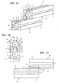
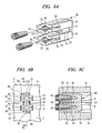
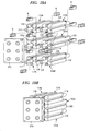
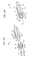
- FIG. 1A is a perspective view showing two blocks fastened as a fastening assembly according to a first embodiment being not according to the present invention
- FIG. 1B is a front view of the two blocks
- FIG. 1C is a side view thereof.
- blocks 1a and 1b which are two members to be fastened are fastened at positions shifted in a longitudinal direction and in a state of contacting with each other.
- Each of the blocks 1a and 1b whose end faces 2 are regular tetragons, is formed into a cuboid, wherein a communication groove 6 opened and extending in the longitudinal direction and an engagement groove 7 communicating with it are formed in each of four side faces 3 thereof and wherein the communication groove 6 and the engagement groove 7 in each of connection surfaces 3c, which contact with each other, are fastened via an insertion fastener 8 serving as a fastener.
- the insertion fastener 8 becomes in a state in which an entirety of the insertion fastener 8 is inserted into and installed in an interior in which the communication groove 6 and the engagement groove 7 formed in each connection surface 3c communicate with each other.
- the communication groove 6 and the engagement groove 7 are formed in each of the four side faces 3.
- the communication groove 6 and the engagement groove 7 may be formed in at least the connection surface 3c of each of the blocks 1a and 1b.
- the end faces 2 of the blocks 1a and 1b are regular tetragons, they may be rectangles.
- the communication groove 6 is formed so as to extend along the side face in the longitudinal direction and be opened, and the engagement groove 7 is formed in each interior of the blocks 1a and 1b so as to continue into the communication groove 6, whereby the entirety thereof is formed into a substantially T-shaped section.
- the communication groove 6 is formed so that its opening width is "Wo" and its opening depth from a surface is "Do”.
- the engagement groove 7 is formed so that its inner width, which is larger than the opening width "Wo", is "Wi” and its inner depth is "Di”. Therefore, side faces, which are disposed on both sides of the communication groove 6 and among inner faces of the engagement groove and arranged to be parallel to the connection surfaces 3c, constitute engagement faces 9.
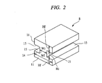
- FIG. 2 is a perspective view of the entirety of the insertion fastener. Note that an upper-right direction of the Figure is a direction of being thrust into the interiors of the communication groove 6 and the engagement groove 7 in insertion direction of the insertion fastener 8 and an opposite lower-left direction is a direction of being pulled out, wherein their directions will be hereinafter referred to as a "thrust direction” and a “pull direction” for convenience of explanations, respectively.
- the insertion fastener 8 in which two engaging pieces 11 are disposed symmetrically in a vertical direction of the Figure and a connecting portion 14 is integrally connected between the engaging pieces 11, is a molded product made of a resin, and is an insertion fastener with the most fundamental structure. Since one of the engaging pieces 11 and the connecting portion 14 are integrally formed, a sectional shape orthogonal to the insertion direction becomes a T-shaped section (see FIG. 1B ).
- the connecting portion 14 is formed so that its linking width "Wc" is almost equal to or smaller than the opening width "Wo" in order to pierce the communication groove 6.
- a linking height "Hc" (i.e., length between the two engaging pieces 11) of the connecting portion 14 is formed with a dimension approximately twice larger than the opening depth "Do" of the communication groove 6.
- the fastening surfaces 15 of the respective engaging pieces 11 contact with the engagement surfaces 9 of the engagement grooves 7, so that the fastening surface 15 cannot be removed from the connection surfaces 3c of the blocks 1a and 1b in the direction orthogonal thereto. Therefore, the two blocks 1a and 1b cannot be separated from each other through the insertion fastener 8, i.e., the two blocks 1a and 1b are firmly fastened to each other via the insertion fastener 8. If each dimension of members constituting the insertion fastener 8 is formed with high accuracy, the two blocks 1a and 1b can be satisfactorily certainly fastened. If they are formed within dimensional tolerances of a tight fit, prevention of extraction and deviation after inserting can be achieved.
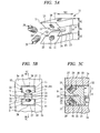
- FIG. 3A is a front view of a structure, as a comparative example, in which the side faces 3 disposed to be parallel to each other on the two blocks 1a and 1b contacting under the same positional relationship as that of FIG. 1 are fastened by bolts via an I-shaped metal-fitting 81
- FIG. 3B is a side view thereof
- FIG. 4A is a front view of a structure in which the connection surfaces 3c and the end faces 2 of the two blocks 1a and 1b contacting with each other are coupled by bolts via an L-shaped metal-fitting 82
- FIG. 4B is a side view thereof.
- a screw hole 84 is provided in an insertion engaging member 83 capable of being inserted into the engagement groove 7.
- the thicknesses of the I-shaped metal-fitting 81 or L-shaped metal-fitting 82 and the heads 86 of the bolt screws are exposed from the surfaces of the blocks 1a and 1b, whereby if the entire assembly is installed into an interior of a device etc., an installation space corresponding to the volume of the exposed thicknesses is required.
- a problem is such that, particularly, when the blocks 1a and 1b constitute a part of a movable body, such exposed thicknesses contact with other members, and electrical wirings, etc.
- the two blocks 1a and 1b in a state of being fastened by the fastening assembly according to the present embodiment shown in FIG. 1 have a structure in which the insertion fastener 8 serving as a fastener is disposed in the interior thereof and there is nothing protruding from the surfaces of the blocks 1a and 1b in spite of being in the fastened state. Therefore, the fastening assembly according to the present embodiment has a fastening structure suitable for saving the installation space required depending on the recent device downsizing.
- the insertion fastener 8 can be inserted into and fastened in such a communicating portion. Therefore, even when the relative arrangements of the two blocks 1a and 1b are arbitrarily changed in a direction of forming the communication grooves 6, the insertion fastener 8 can be inserted therein and fastened thereto. Further, only one insertion fastener 8 is inserted in FIG. 1 .
- the insertion fastener 8 can be inserted not only into openings formed at two positions of both ends of the communicating range but also into arbitrary positions within the communicating range. Therefore, fastening locations can be also set at arbitrary positions.
- the insertion fastener 8 shown in FIG. 2 is made of a resin, and may be made of metal.
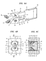
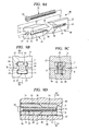
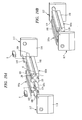
- FIG. 5A is a perspective view of an entirety of an inclined fastening metal-fitting which is a fastener used in a fastening assembly according to a second embodiment being not according to the present invention
- FIG. 5B is a front view of a state of inserting the inclined fastening metal-fitting into one set of communication groove 6 and engagement groove 7 which are opposed to each other similarly to that of the above-described first embodiment
- FIG. 5C is an insertion-directional cross-sectional view taken along line 5C-5C of FIG. 5B .
- members and shapes used in common with the fastening assembly shown in FIG. 1 are denoted by the same reference numerals.
- the inclined fastening metal-fitting 22 has a spring-steel molded product in which two engaging pieces 11 are disposed symmetrically in the vertical direction of the Figures and a connecting portion 14 is integrally coupled between the engaging pieces 11.
- a coupling portion 23 on a thrust-directional side thereof is left and a pull-directional side thereof is divided by a linking division groove 24. Since one of the engaging pieces 11 is integrally connected to a base end of the connecting portion 14, a sectional shape orthogonal to the insertion direction becomes a "T" shape (see FIG. 5B ).
- the connecting portion 14 is formed to have the linking width "Wc" almost equal to the opening width "Wo” for being capable of piecing the communication groove 6, and the linking height "Hc" of the connecting portion 14 (i.e., length between the two engaging pieces 11) is formed with a dimension approximately twice larger than the opening depth "Do" of the communication groove 6.
- the engagement width "Wf" of the engaging piece 11 is formed to be larger than the opening width "Wo” so that the fastening surfaces 15 can be contacted and engaged with the engagement surfaces 9 of the engagement grooves 7.
- the engagement width "Wf” of the engaging piece 11 is formed to be almost equal to or smaller than the inner width "Wi” to be inserted into the engagement groove 7.
- the engagement height "Hf” is formed by such a dimension as to be almost equal to or smaller than the inner depth "Di" to be inserted into the engagement groove 7.
- the entirety of the inclined fastening metal-fitting 22 having the above-described structure can be inserted into the interiors of one set of communication groove 6 and engagement groove 7, which are opposed to and communicate with each other as shown in FIG. 5 , by being thrust in the insertion direction.
- the end faces (tip faces) on a pull-directional side of the engaging pieces 11 form inclined surfaces 25 opposed to each other and forming an acute angle with respect to each of connection surfaces 3c of the blocks 1a and 1b, and the end faces on the thrust-directional side of the entire inclined fastening metal-fitting 22 are formed on the same plane.
- a screw hole 26 is formed in each engaging piece 11 in a direction substantially orthogonal to the inclined surface 25, and the screw hole 26 pierces up to an outer surface 27 parallel to the fastening surface 15.
- a setscrew 29 (screw member) whose tip 28 is taped as a fastening member is attached to each screw hole 26.
- the fastening surfaces 15 of the engaging pieces 11 are strongly pressed in a direction of approaching each other due to a reaction force to an abutment force between the tips 28 of the setscrews and the bottom faces 10 of the engagement grooves.
- the two communication grooves 6 under the opposite states are strongly clamped via the engagement surfaces 9. Therefore, the inclined fastening metal-fitting 22 serving as a fastener applies a fastening force to the two blocks 1a and 1b, thereby becoming capable of further firmly fastening them.
- the coupling portion 23 serves as a bending location and the entirety of the inclined fastening metal-fitting 22 can be readily elastically deformed in a direction in which the fastening surfaces 15 approach each other. Therefore, the engaging pieces 11 can be readily pressed against the communication grooves 6.
- the setscrews 29 are turned backward to eliminate the pressing forces of the engaging pieces 11.
- FIG. 6A is a perspective view of an entirety of the inclined fastening metal-fitting 22 and of a positioning plate 30 used for it in the present embodiment
- FIG. 6B is a front view of a state of incorporating the positioning plate 30 into one set of communication groove 6 and engagement groove 7 which are opposed to each other and of inserting the inclined fastening metal-fitting 22 therein
- FIG. 6C is an insertion-directional cross-sectional view taken along line 6C-6C of FIG. 6B .
- members and shapes used in common with the fastening assembly shown in FIG. 5 are denoted by the same reference numerals.
- the positioning plate 30 is made of a plate material bent into a substantially U shape so as to surround the end face on the thrust-directional side and two outer surfaces 27 of the inclined fastening metal-fitting 22, and has such a shape that locking claws 31 contacting with the end faces of the two members to be fastened are provided at both ends thereof.
- the positioning plate 30 is attached to the inclined fastening metal-fitting 22 in a state in which the two blocks 1a and 1b contact with each other while the end faces 2 thereof are aligned.
- the positioning plate 30 may be first inserted into the interiors of the set of communication groove 6 and engagement groove 7 which are opposed to each other, and then the inclined fastening metal-fitting 22 may be installed at the insides thereof.
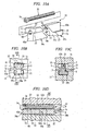
- FIG. 7A is a perspective view of the entirety of an enlarging divided metal-fitting serving as a fastener used in a fastening assembly according to a third embodiment being not according to the present invention
- FIG. 7B is a front view of the enlarging divided metal-fitting installed in the interiors of the set of communication groove 6 and engagement groove 7 which are opposed to each other
- FIG. 7C is an insertion-directional cross-sectional view taken along line 7C-7C of FIG. 7B .
- members and shapes used in common with the fastening assembly shown in FIG. 5 are denoted by the same reference numeral.
- the enlarging divided metal-fitting 32 integrally has the two engaging pieces 11 which are disposed symmetrically in the vertical direction of the Figures, and the connecting portion 14 between the engaging pieces 11 is integrally formed therewith.
- the coupling position 23 thereof is left on the thrust-directional side, and is divided mostly (about two thirds) on the pull-directional side by the linking dividing groove 24.
- a protruding portion 33 is formed on the outer surface 27 of each of the engaging pieces 11 in the longitudinal direction, and a periphery of each engaging piece 11 is such that its sectional shape orthogonal to the insertion direction is substantially cross-like (see FIG. 7B ).
- accommodating grooves 34 into which the protruding portions 33 can be inserted are formed in the bottom faces of the engagement grooves on sides of the fastened blocks 1a and 1b. As shown in FIG.
- the enlarging divided metal-fitting 32 having the above-described structure is thrust in the insertion direction into the interiors of the set of communication groove 6 and engagement groove 7 which are opposed to and communicate with each other, so that the entirety thereof can be inserted thereto.
- each engaging piece 11 on the pull-directional side is separated into an outer elastic deformation portion 36 and an inner elastic deformation portion 37 respectively in the vertical direction of the Figures, by an engaging-piece dividing groove 35 serving as a cut-in portion.
- a screw hole 38 is formed at a center of the engaging-piece dividing groove 35.
- a tapered round surface having no screw thread is formed in each screw hole 38 on the pull-directional side.
- a flat head screw 39 whose bearing surface has a comparatively large taper, is attached as a fastening member to each screw hole 38.
- FIG. 8A is a perspective view of an entirety of a modification example of the enlarging divided metal-fitting shown in FIG. 7
- FIG. 8B is a front view of the modification example of the enlarging divided metal-fitting installed in the interiors of one set of communication groove 6 and engagement groove 7 which are opposed to each other similarly to the above-described first embodiment
- FIG. 8C is an insertion-directional cross-sectional view taken along line 8C-8C of FIG. 8B .
- members and shapes used in common with the fastening assembly shown in FIG. 7 are denoted by the same reference numerals.
- screw threads are formed in a tapered manner over the entirety of the screw hole 41 formed on the engaging-piece dividing groove 35 in the length direction, and a tapered screw is formed in the length direction over the entirety of a screw member 42 (fastening member) to be screw-connected to the screw hole 41.
- a structure other than this is the same as that of the enlarging divided metal-fitting 32 shown in FIG. 7 .
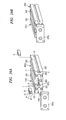
- FIG. 9A is a perspective view of an entirety of a wedge dividing metal-fitting serving as a fastener used in a fastening assembly according to a fourth embodiment being not according to the present invention
- FIG. 9B is a front view of the wedge dividing metal-fitting installed in the fastened state in the interiors of one set of communication groove 6 and engagement groove 7 which are opposed to each other
- FIG. 9C is a cross-sectional view taken along line 9C-9C of FIG. 9D
- FIG. 9D is an insertion-directional cross-sectional view taken along line 9D-9D of FIG. 9B .
- members and shapes common used in with the fastening assembly shown in FIG. 5 are denoted by the same reference numerals.
- the wedge dividing metal-fitting 46 is constituted so that two of a wedge metal-fitting 47 on the pull-directional side and a clamp metal-fitting 48 on the thrust-directional side (fastening pieces) are assembled in the insertion direction via a screw member.
- Each of the wedge metal-fitting 47 and the clamp metal-fitting 48 has a height almost equal to a distance (2Do + 2Di) from the bottom face 10 of one engagement groove of one set of communication groove 6 and engagement groove 7 communicating with each other to the bottom face 10 of the other engagement groove, so that the wedge metal-fitting 47 is formed to have a width almost equal to the inner width "Wi" and the clamp metal-fitting 48 is formed to have a width almost equal to the opening width "Wo".
- the wedge metal-fitting 47 integrally includes, at both ends in the vertical direction of the Figures, the engaging pieces 11 which can be inserted into the engagement grooves 7. Between the two upper and lower engaging pieces 11, the coupling portion 23 on the pull-directional side is left and most thereof on the thrust-directional side is divided by the linking dividing groove 24 in the vertical direction of the Figure.
- Each of end faces on the thrust-directional side of parts divided upper and lower forms an inclined face 49 (abutting face) forming an obtuse angle with respect to the outer surface 27 of each engaging piece 11.
- the clamp metal-fitting 48 is such that the coupling portion 23 on the thrust-directional side is left and most thereof on the pull-directional side is divided by the linking dividing groove 24 in the vertical direction of the Figures.
- End faces of vertically divided parts on the pull-directional side form inclined surfaces 50 (abutting faces), which are formed with such angles that they become parallel to the mutually opposing inclined surfaces 49 serving as end faces of the wedge metal-fitting 47.
- a hole penetrated in the insertion direction is formed in each of both the coupling portions 23 of the wedge metal-fitting 47 and the clamp metal-fitting 48, wherein the hole of the wedge metal-fitting 47 is merely a through hole 51 on which no screw thread is formed and the hole of the clamp metal-fitting 48 is a screw hole 52 on which a screw thread is formed.
- a bolt screw 53 is inserted from the end face of the wedge metal-fitting 47 on the pull-directional side, a bolt-screw head 54 is engaged with the end face on the pull-directional side, and a screw part of the bolt screw 53 is screw-connected to the screw hole 52 of the clamp metal-fitting, so that the wedge metal-fitting 47 and the clamp metal-fitting 48 are assembled.
- the wedge dividing metal-fitting 46 having the above-mentioned structure is thrust into the interiors of the set of communication groove 6 and engagement groove 7 which are opposed to and communicate with each other, whereby the entirety thereof can be inserted.
- the bolt screw 53 is turned so that the wedge metal-fitting 47 and the clamp metal-fitting 48 are strongly pressed against each other, pressing component forces in a direction of approaching each other act on the engaging pieces 11 of the wedge metal-fitting 47 due to contact sliding caused between the inclined surfaces 49 and 50 as shown in FIG. 9D .
- the outer surfaces 27 of the clamp metal-fitting 48 abut on the bottom faces 10 of the engagement grooves, thereby being not deformed any more.
- the clamp metal-fitting 48 and the bolt screw 53 serves as a fastening member in the wedge dividing metal-fitting 46. Accordingly, the fastening surfaces 15 of the engaging pieces 11 of the wedge metal-fitting 47 are strongly pressed in the direction of approaching each other, whereby the two mutually opposed communication grooves 6 are strongly clamped via the engagement surfaces 9.
- the firm fastening without anything protruding from the surfaces of the blocks 1a and 1b can be carried out.
- the positioning plate 30 shown in FIG. 6 can be applied to the wedge dividing metal-fitting 46 of the present embodiment.
- FIG. 10A is a perspective view of an entirety of an inclined dividing metal-fitting serving as a fastener used in a fastening assembly according to a fifth embodiment representing the present invention
- FIG. 10B is a front view of the inclined dividing metal-fitting installed in the fastened state in the interiors of one set of communication groove 6 and engagement groove 7 which are opposed to each other
- FIG. 10C is a cross-sectional view taken along line 10C-10C in FIG. 10D
- FIG. 10D is an insertion-directional cross-sectional view taken along line 10D-10D of FIG. 10B .
- members and shapes used in common with the fastening assembly shown in FIG. 9 are denoted by the same reference numerals.
- the inclined dividing metal-fitting 57 is constituted so that two trapezoidal metal-fittings 58a and 58b thereof on the pull-directional side and the thrust-directional side are assembled in the insertion direction via a screw member.
- the trapezoidal metal-fittings 58a and 58b have connecting portions 62a and 62b (first connecting portion and second connecting portion), each of which is formed with a height almost equal to a distance (2Do + 2Di) from the bottom face 10 of one of the engagement grooves in the set of communication groove 6 and engagement groove 7 communicating with each other to the bottom face 10 of the other engagement groove and with a width almost equal to the opening width "Wo" of the communication groove 6.
- These connecting portions 62a and 62b are arranged so as to be opposed to each other by mutually parallel inclined surfaces 59a and 59b (abutting faces).
- the connecting portion 62b of the trapezoidal metal-fitting 58a on the pull-directional side integrally includes the engaging piece 11 capable of being inserted into the engagement groove 7 at the upper-side end of the Figures
- the connecting portion 62b of the trapezoidal metal-fitting 58b on the thrust-directional side integrally includes the engaging piece 11 capable of being inserted into the engagement groove 7 at the lower-side end of the Figures.
- the two engaging pieces 11 are arranged so that the respective fastening surfaces 15 are mutually shifted in the longitudinal direction and opposed to each other.
- Each of the inclined surfaces 59a and 59b of the two trapezoidal metal-fittings 58a and 58b opposed to each other forms an obtuse angle with respect to the outer surface 27 on a side on which the engaging piece 11 is provided.
- a hole penetrating the entirety of the inclined dividing metal-fitting 57 in the insertion direction is formed at a height level including the engaging piece 11 of the trapezoidal metal-fitting 58a on the pull-directional side.
- the hole of the trapezoidal metal-fitting 58a on the pull-directional side is merely a through hole 60 on which no screw thread is formed, and the hole of the trapezoidal metal-fitting 58b on the thrust-directional side is a screw hole 61 on which a screw thread is formed.
- the bolt screw 53 (screw member) is inserted from the pull-directional-side end face of the trapezoidal metal-fitting 58a on the pull-directional side and the bolt-screw head 54 is engaged with the end face on the pull-directional side and the screw part of the bolt screw 53 is screwed in a screw hole 61 of the trapezoidal metal-fitting 58b on the thrust-directional side, so that the two trapezoidal metal-fittings 58a and 58b are assembled.
- the inclined dividing metal-fitting 57 having the above-mentioned structure is thrust into the interiors of the set of communication groove 6 and engagement groove 7 which are opposed to and communicate with each other, the entirety thereof can be inserted.
- the bolt screw 53 is turned to increase the pressing force acting mutually between the two trapezoidal metal-fittings 58a and 58b, as shown in FIG. 10D , the pressing component force in the mutually opposing directions, i.e., in the upward direction and the downward direction of the Figures acts on the trapezoidal metal-fittings 58a and 58b due to the contact sliding between the inclined surfaces 59a and 59b.
- the pressing component force directed downward in the Figures acts on the trapezoidal metal-fitting 58a on the pull-directional side and the pressing force directed upward in the Figures acts on the trapezoidal metal-fitting 58b on the thrust-directional side. Accordingly, the fastening surfaces 15 of the engaging pieces 11 of the respective trapezoidal metal-fittings 58a and 58b are strongly pressed in the direction of approaching each other, whereby the two opposing communication grooves 6 are strongly clamped via the engagement surfaces 9.
- the firm fastening without anything protruding from the surfaces of the blocks 1a and 1b can be carried out.
- the positioning plate 30 shown in FIG. 6 can be applied to the inclined dividing metal-fitting 57 of the present embodiment.
- FIG. 11A is a perspective view of an entirety of an H-shaped metal-fitting serving as a fastener used in a fastening assembly according to a sixth embodiment being not according to the present invention
- FIG. 11B is a front cross-sectional view of the H-shaped metal-fitting installed in a state of being fastened in the interiors of one set of communication groove 6 and engagement groove 7 which are opposed to each other. If each length of the members to be fastened, the communication groove 6, and the engagement groove 7 is larger than that of an ordinary case in comparison with the width of each groove, the H-shaped metal-fitting 63 of the present embodiment is an intermediate fastener for fastening an intermediate position thereof.
- members and shapes used in common with the fastening assembly shown in FIG. 2 are denoted by the same reference numerals.
- the H-shaped metal-fitting 63 is formed integrally so that the two engaging pieces 11 capable of being inserted into the engagement grooves 7 are disposed symmetrically in the vertical direction of the Figures by sandwiching the connecting portion 14 therebetween.
- the H-shaped metal-fitting 63 with such a structure can be entirely inserted into the interiors of one set of communication groove 6 and engagement groove 7 which are opposed to and communicate with each other.
- a screw hole 64 penetrating the H-shaped metal-fitting 63 in a direction orthogonal to the outer surfaces 27 of the engaging pieces 11 is formed, and a setscrew 65 is attached to the inside thereof. Note that when this intermediate fastener is used, an accommodating groove 67 on which a tip 66 of the setscrew abuts is desirably formed on the bottom face 10 of the engagement groove as shown in the Figures.
- the engaging piece 11 on a side, on which the tip 66 of the setscrew is disposed in the engagement groove 7 of the lower-side block 1b of FIG. 11 is inserted from an opening of an end of the engagement groove 7, thereby being disposed at a predetermined middle position of the engagement groove 7 in its longitudinal direction.
- the setscrew 65 is screwed thereto so as to abut the tip 66 of the setscrew and the bottom face of the accommodating groove 67, whereby the fastening surfaces 15 of the engaging pieces 11 is pressed against the engagement surfaces 9 of the engagement grooves 7 by a reaction force thereof and the H-shaped metal-fitting 63 is fixed to the communication groove 6 and engagement groove 7 of one block 1b.
- FIG. 12A is a perspective view of an entirety of a flat inclination H-shaped metal-fitting which is a first modification example of the intermediate fastener
- FIG. 12B is a front cross-sectional view taken along line 12B-12B of FIG. 12C showing the flat inclination H-shaped metal-fitting installed in the interiors of one set of communication groove 6 and engagement groove 7 which are opposed to each other
- FIG. 12C is a plane cross-sectional view taken along line 12C-12C of FIG. 12B .
- members and shapes used in common with the fastening assembly shown in FIG. 11 are denoted by the same reference numerals.
- a flat inclination H-shaped metal-fitting 71 has the two engaging pieces 11, each of which is formed into a prismatic shape having a parallelogram section in which front and rear end faces 72a and 72b viewed from the outer surface 27 thereof are inclined by an angle "X" with respect to the insertion direction, wherein the width in a direction orthogonal to the insertion direction is equal to the inner width "Wi" of the engagement groove 7 and a distance between the two parallel end faces 72a and 72b is formed to be equal to the opening width "Wo" of the communication groove 6.
- the connecting portion 14 is formed into a cylindrical shape with a diameter equal to the opening width "Wo" of the communication groove 6.
- the fastener of this modification example even when the communication grooves 6 and the engagement grooves 7 are long in the longitudinal direction, the fastener can be readily installed from the longitudinal-directional intermediate positions without being inserted from the openings of the ends of the communication groove 6 and the engagement groove 7. Under a state of the good posture, the posture can be certainly fixed since both width-directional ends of each engaging piece 11 surface-contact with both width-directional side faces of the engagement groove 7.
- one of the engaging pieces 11 may be formed into a prismatic shape having a parallelogram section capable of passing through the communication groove 6 and the other of the engaging pieces 11 may be formed into a cuboid as shown in FIG. 11 .
- FIG. 13A is a perspective view of an entirety of a flat round H-shaped metal-fitting which is a second modification example of the intermediate fastener;
- FIG. 13B is a front cross-sectional view taken along line 13B-13B of FIG. 13C showing the flat round H-shaped metal-fitting installed in the interiors of one set of communication groove 6 and engagement groove 7 which are opposed to each other;
- FIG. 13C is a plane cross-sectional view taken along line 13C-13C of FIG. 13B .
- members and shapes used in common with the fastening assembly shown in FIG. 11 are denoted by the same reference numerals.
- a flat round H-shaped metal-fitting 73 in which the entire thickness with respect to the insertion direction is equal to the opening width "Wo" of the communication groove 6 and both width-directional ends of each engaging piece 11 each have a cylindrical side face 74 with a diameter equal to the inner width "Wi" of the engagement groove 7.
- the fastener can be readily installed from the intermediate positions of the communication groove 6 and the engagement groove 7 in the longitudinal direction.
- only one of the engaging pieces may be formed to have such thickness as to be capable of passing through the communication groove 6.
- Fastening by use of the fastening assemblies of the above-described embodiments is not limited to the case where mere blocks are fastened as shown in FIG. 1 , and is also suitable for, for example, mutually fastening manifolds 20 in a stacking valve 19 as shown in FIG. 14 .
- externally fixed rails etc. for fixing the manifolds 20 are not particularly required, and many manifolds 20 can be added and fixed without being limited by the length of such externally fixed rails.
- This case is advantageous in that the manifolds 20 and solenoid valves 21 fixed thereon can be easily attached, detached, or replaced by thrusting into or pulling out the fasteners (insertion fasteners 8).
- fastening by use of the fastening assemblies of the above-described embodiments is also suitable for, for example, as shown in FIG. 15 , the case where a plurality of fluid pressure cylinders 16 are mutually fastened by cylinder tubes 17 so as to constitute a fluid pressure cylinder unit.
- a driving force can be increased.
- the piston rods 18 so as to be mutually disposed on the opposite side as described blow, the total length of a stroke can be doubled.
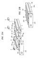
- FIG. 16 is a perspective view of an entirety of a fluid pressure cylinder unit according to a first embodiment of the present invention, wherein FIG. 16A is a perspective view showing a before-assembly state and FIG. 16B is a perspective view showing an assembled state.
- Each of two fluid pressure cylinders 101a and 101b is a pneumatic cylinder employing compressed air as working fluid (fluid pressure), wherein a piston rod 104 protrudes from one end face 103 of each of the cylinder tubes 102 serving as two members to be fastened.
- the piston rod 104 is provided so that an object to be driven can be driven reciprocably in a straight-line direction when the compressed air is fed or discharged through an unshown feed/discharge port.
- the fluid pressure cylinders used in the embodiments are assumed to be pneumatic cylinders.
- the piston rods 104 thereof are disposed in the same direction and in parallel to each other, the cylinder tubes 102 are made to contact with each other by connection surfaces 105c thereof to be fastened via the insertion fastener 8 serving as a fastener, and a common tip plate 107a serving as a linking member is attached to the tips of the piston rods 104, whereby a twin rod cylinder is constituted.
- the two cylinder tubes 102 to be fastened serve mutually as attachments.
- Each of the cylinder tubes 102 is such that its end face 103 is substantially square and its entirety is a long cuboid shape in an axial direction of the piston rod 104.
- the communication groove 6 opened and extending in a longitudinal direction along an axial direction and the engagement groove 7 communicating therewith are formed in each of four side faces 105 thereof, and the communication grooves 6 and the engagement grooves 7 of the connection surfaces 105c contacting with each other are coupled via the insertion fasteners 8 serving as fasteners.
- the entirety of the insertion fastener 8 is inserted into and installed in the interiors of the set of communication groove 6 and engagement groove 7 which are in opposed and communicated states.
- the communication groove 6 and the engagement groove 7 are formed in each of the four side faces 105, the communication groove 6 and the engagement groove 7 may be formed at least only in the connection surfaces 105c by which the cylinder tubes 102 contact with each other. Note that although shapes of the end faces 103 of the cylinder tubes 102 are square, they may be rectangular.
- the pneumatic cylinder unit of the present embodiment shown in FIG. 16 has a structure in which the insertion fasteners 8 serving as fasteners are accommodated and disposed in the interiors of the two cylinder tubes 102 and there is nothing protruding from the surfaces of the cylinder tubes 102 in spite of a fastened state. Therefore, the pneumatic cylinder unit of the present embodiment has a fastening structure suitable for saving the installation spaces depending on recently downsizing of the devices.
- the insertion fastener 8 can be inserted into and fastened on such a communicating location. Therefore, even when the relative arrangement between the two cylinder tubes 102 is arbitrarily changed depending on a direction of forming the communication grooves 6, fastening can be carried out by inserting the insertion fastener 8. In addition, if a region in which the communication grooves 6 are mutually communicated is sufficiently long, the insertion fastener 8 can be inserted at arbitrary position within the communicating region. Therefore, fastening locations can be also set at arbitrary positions.
- the pneumatic cylinder unit of the present embodiment has a structure in which since the two pneumatic cylinders 101a and 101b disposed parallel are certainly fastened in the above-described manner and the same tip plate 107a is driven, the driving force is almost doubled in comparison with the case of being driven by one pneumatic cylinder and rigidity is enhanced.
- FIG. 17 is a perspective view of an entirety of a pneumatic cylinder unit according to a second embodiment of the present invention, wherein FIG. 17A is a perspective view showing a before-assembly state and FIG. 17B is a perspective view showing an assembled state.
- FIG. 17A is a perspective view showing a before-assembly state
- FIG. 17B is a perspective view showing an assembled state.
- members and shapes used in common with the pneumatic cylinder unit shown in FIG. 16 are denoted by the same reference numerals.
- the guide units 114a and 114b are such that, with respect to the guide blocks 116 serving as members to be fastened, the same guide rods 115 between both ends thereof is made to pierce and protrude and be installed extendably and retractably and the guide rod 115 is supported in the guide block 116 by a ball bearing (not shown) so as to be slid smoothly.
- the guide block 116 has end faces, each of which has the same shape as that of the cylinder tube 102, and is a cuboid shape axially shorter in length than the cylinder tube 102, wherein the communication groove 6 and the engagement groove 7 are formed in each of the four side faces thereof.
- each guide block 116 becomes in a state of being fastened to the cylinder tube 102.
- the above-described pneumatic cylinder unit of the present embodiment has a fastening structure suitable for saving the installation spaces similarly to the above-described first embodiment and is constituted so that since two guide units 114a and 114b guide the pneumatic cylinder 101a, a stable operation can be obtained even if the tip plate 107b is long.
- the guide block 116 may be formed with the same length as that of the cylinder tube 102, and the ball bearing provided in the guide block 116 may be a slide bearing.
- FIG. 18 is a perspective view of an entirety of a pneumatic cylinder unit according to a third embodiment of the present invention, wherein FIG. 18A is a perspective view showing a before-assembly state and FIG. 18B is a perspective view showing an assembled state.
- FIG. 18A is a perspective view showing a before-assembly state
- FIG. 18B is a perspective view showing an assembled state.
- members and shapes used in common with the pneumatic cylinder unit shown in FIG. 16 are denoted by the same reference numerals.
- the piston rods 104 are arranged parallel and in the same direction, and the cylinder tubes 102 are made to contact with each other by the connection surfaces 105c and are fastened via the insertion fastener 8.
- a common tip plate 107c serving as a linking member is attached to all the tips of the piston rods 104 and the guide rods 115, whereby a lifter cylinder is constituted.
- the two fastened cylinder tubes 102 serve mutually as attachments
- other four guide blocks 116 serves as attachments that are fastened on the two cylinder tubes 102.
- the above-described pneumatic cylinder unit has a fastening structure suitable for saving the installation spaces similarly to the above-described first embodiment, and is constituted so that since two sets of guide unit pairs 114a and 114b, and 114c and 114d guide one set of pneumatic cylinder pair 101a and 101b, a doubled driving force and a stable operation can be obtained with respect to the tip plate 107c having an area approximately 2 x 3 times larger than a section of the cylinder tube 102.
- FIG. 19 is a perspective view of an entirety of a pneumatic cylinder unit according to a fourth embodiment of the present invention, wherein FIG. 19A is a perspective view showing a before-assembly state and FIG. 19B is a perspective view showing a assembled state.
- FIG. 19A is a perspective view showing a before-assembly state
- FIG. 19B is a perspective view showing a assembled state.
- members and shapes used in common with the pneumatic cylinder unit shown in FIG. 16 are denoted by the same reference numerals.
- the respective piston rods 104 are arranged in opposite direction and in parallel to each other, the cylinder tubes 102 are made to contact with each other by the connection surfaces 105c and fastened via the insertion fasteners 8, and chuck plates 117 serving as chuck members are attached to the respective piston rods 104, whereby an air chuck is constituted.
- the two cylinder tubes 102 fastened serve mutually as attachments.
- Each chuck plate 117 has a gripper 118 formed to extend from a connection position with the piston rod 104 in a lower direction of the Figures, and a support rod 119 is attached to each chuck plate 117.
- a support rod hole 120 is formed in an end face 103 located on a side opposite to an extension side of the piston rod 104, and the support rod 119 is slidably inserted into the support rod hole 120 in being assembled. That is, each chuck plate 117 is stably supported by two members of the piston rod 104 and the support rod 119, and drive for reciprocation with respect to the cylinder tubes 102 is carried out by movement of the piston rods 104. When the two chuck plates 117 are reciprocated, an opening/closing operation between the chuck plates 117 is carried out.
- the above-described pneumatic cylinder unit of the present embodiment has a fastening structure suitable for saving the installation spaces similarly to the above-described first embodiment, and is constituted so that by performing the opening/closing operation between the chuck plates 117, some workpiece etc. therebetween can be gripped.
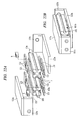
- FIG. 20 is a perspective view of an entirety of a pneumatic cylinder unit according to a fifth embodiment of the present invention, wherein FIG. 20A is a perspective view showing a before-assembly state and FIG. 20B is a perspective view showing an assembled state.
- FIG. 20A is a perspective view showing a before-assembly state
- FIG. 20B is a perspective view showing an assembled state.
- members and shapes used in common with the pneumatic cylinder unit shown in FIG. 16 are denoted by the same reference numerals.
- the respective piston rods 104 are arranged parallel and in the same direction, the cylinder tubes 102 are made to contact with each other by the connection surfaces 105c to be fastened via the insertion fasteners 8 serving as fasteners, and a common tip plate 107d serving as a linking member is attached to the tips of the piston rods 104.
- Guide rails 121 are disposed parallel on the two side faces 105 located parallel on the respective pneumatic cylinders 101a and 101b, two guide plates 122 are slidably installed on each of the guide rails 121, and a common slide table 123a attached to the guide plates 122 is connected to the piston rods 104 via the tip plate 107d, whereby a table-attached twin guide cylinder is constituted.
- the two cylinder tubes 102 to be fastened serve mutually as attachments.
- the guide rail 121 is formed into a cuboid having a rail width "Wr” larger than the opening width "Wo” and a rail height "Hr", i.e., almost the same height as that of the cylinder tube 102 so as not to pierce the communication groove 6, and therefore is disposed so as to overlap with the communication groove 6 and combined and fixed with the nut and screw inserted into the engagement groove 7, thereby being fixed.
- the guide plate 122 is a plate material formed into a square whose one side has almost the same width as that of the cylinder tube 102.
- the slide table 123a is a rectangular plate material having almost the same width as that of a total of two pneumatic cylinders 101a and 101b, and is screwed on the four guide plates 122, whose two are serially arranged on each guide rail 121, and is fixed to one side face of the tip plate 107d attached to the piston rods 104. That is, the slide table 123a can apply a load to the side faces 105 of the cylinder tubes 102 via the guide plates 122 and the guide rails 121 and reciprocate axially by the operations of the piston rods 104.
- the above-described pneumatic cylinder unit of the present embodiment has a fastening structure suitable for saving the installation spaces similarly to the above-described first embodiment and has a structure in which a stably reciprocating operation can be carried out by a doubled driving force while the loads are applied from the vertical and lateral directions of the cylinder tubes 102.
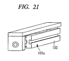
- the table-attached guide cylinder includes a structure of a table-attached single guide cylinder having only one pneumatic cylinder 101a and formed with half of the entire width; as shown in FIG. 21 .
- FIG. 22 is a perspective view of an entirety of a pneumatic cylinder unit according to a sixth embodiment of the present invention, wherein FIG. 22A is a perspective view showing a before-assembly state and FIG. 22B is a perspective view showing an assembled state.
- FIG. 22A is a perspective view showing a before-assembly state
- FIG. 22B is a perspective view showing an assembled state.
- members and shapes used in common with the pneumatic cylinder unit shown in FIG. 16 are denoted by the same reference numerals.
- the respective piston rods 104 are mutually arranged parallel and in an opposite direction, the cylinder tubes 102 are made to contact with each other by the connection surfaces 105c to be fastened via the insertion fasteners 8, and a tip plate 107e is attached to the respective piston rods 104.
- Two guide rails 121 and four guide plates 122 are installed on each of upper and lower surfaces of the entire pneumatic cylinder pair 101a and 101b, and the slide tables 123a attached to the faces are linked to the piston rods 104 via the tip plates 107e located on the opposite side, whereby a double-stroke cylinder is constituted.
- the two cylinder tubes 102 to be fastened serve mutually as attachments.
- the above-described pneumatic cylinder unit of the present embodiment has a fastening structure suitable for saving the installation spaces similarly to the above-described first embodiment, and is constituted so that the staple reciprocating operation can be carried out by the doubled stroke while the loads are applied from the vertical and lateral directions of the cylinder tubes 102.
- FIG. 23 is a perspective view of an entirety of a pneumatic cylinder unit according to a seventh embodiment of the present invention, wherein FIG. 23A is a perspective view showing a before-assembly state and FIG. 23B is a perspective view showing an assembled state.
- FIG. 23A is a perspective view showing a before-assembly state
- FIG. 23B is a perspective view showing an assembled state.
- members and shapes used in common with the pneumatic cylinder unit shown in FIG. 16 are denoted by the same reference numerals.
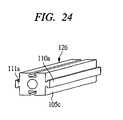
- the respective piston rods 104 are directed to the same direction and are all arranged parallel so as to sandwich a spacer block 125 therebetween.
- the two pneumatic cylinders 101a and 101b and the spacer block 125 are mutually made to contact with each other by the connection surfaces 105c and fastened via the insertion fasteners 8 serving as fasteners, and a common tip plate 107f serving as a linking member is attached to the tips of the two piston rods 104, whereby a spacer-attached twin-rod cylinder is constituted.
- the spacer block 125 and the two cylinder tubes 102 to be fastened serve mutually as attachments.
- the spacer block 125 has a cuboid shape with the same dimensions as those of the cylinder tube 102, wherein the communication groove 6 and the engagement groove 7 are formed in each of four side faces 105 thereof.
- the communication groove 6 and the engagement groove 7 may be formed only in at least the respective connection surfaces 105c connected to the cylinder tubes 102.
- FIG. 23 shows that the communication groove 6 and the engagement groove 7 may be formed only in at least the respective connection surfaces 105c connected to the cylinder tubes 102.
- the spacer block may be a spacer block 126 having preliminarily a shape of a half portion of a fastener on the connection surfaces 105c with the cylinder tubes, i.e., having a shape of halves of the connecting portion 14 and the engaging pieces 11.
- the fastener does not require being prepared as independent parts.
- the above-described pneumatic cylinder unit of the present embodiment has a fastening structure suitable for saving the installation spaces similarly to the above-described first embodiment, and is constituted so that the driving force is doubled and further the rigidity is enhanced.
- FIG. 25 is a perspective view of an entirety of a pneumatic cylinder unit according to an eighth embodiment of the present invention, wherein FIG. 25A is a perspective view showing a before-assembly state and FIG. 25B is a perspective view showing an assembled state.
- FIG. 25A is a perspective view showing a before-assembly state
- FIG. 25B is a perspective view showing an assembled state.
- members and shapes used in common with the pneumatic cylinder units shown in FIG. 16 and FIG. 23 are denoted by the same reference numerals.
- the guide units 114a and 114b are disposed on both sides of one pneumatic cylinder 101a regarded as a center, and the pneumatic cylinder 101a and the guide units 114a and 114b sandwich the spacer block 125 therebetween and all are disposed parallel. They are made to contact with each other by the connection surfaces 105c and fastened via the insertion fasteners 8 serving as fasteners, and a common tip plate 107g serving as a linking member is attached to the all tips of the piston rods 104 and the guide rods 115, whereby a spacer-and-guide-attached cylinder is constituted.
- the two spacer blocks 125 and the two guide blocks 116 serve as an attachment fastened to the cylinder tube 102.
- the above-described pneumatic cylinder unit of the present embodiment has a fastening structure suitable for saving the installation spaces similarly to the above-described first embodiment, and is constituted so that an stable operation can be carried out with high rigidity even if the tip plate 107g is formed into an elongated shape equal to a total of sectional dimensions of the five cylinder tubes 102.
- FIG. 26 is a perspective view of an entirety of a pneumatic cylinder unit according to a ninth embodiment of the present invention, wherein FIG. 26A is a perspective view showing a before-assembly state and FIG. 26B is a perspective view showing an assembled state.
- FIG. 26A is a perspective view showing a before-assembly state
- FIG. 26B is a perspective view showing an assembled state.
- members and shapes used in common with the pneumatic cylinder units shown in FIGs. 16 , 20 , and 23 are denoted by the same reference numerals.
- the piston rods 104 are respectively directed to the same direction and sandwich the spacer block 125 therebetween, whereby all are arranged parallel. They are made to contact with each other by the connection surfaces 105c and fastened via the insertion fasteners 8 serving as fasteners, and a common tip plate 107h serving as a linking member is attached to the tips of the two piston rods 104.
- the guide rail 121 is installed parallel on each of the two side faces 105 located in parallel to the respective pneumatic cylinders 101a and 101b, two guide plates 122 are slidably installed on each of the guide rails 121, and a common slide table 123b attached to the guide plates 122 is connected to the piston rods 104 via the tip plate 107h, whereby a table-and-spacer-attached twin guide cylinder is constituted.
- the spacer block 125 and the two cylinder tubes 102 to be fastened serve mutually as attachments.
- the above-described pneumatic cylinder unit of the present embodiment has a fastening structure suitable for saving the installation spaces similarly to the above-described first embodiment, and is constituted so that the driving force is doubled and further the rigidity is enhanced while the loads are applied from the vertical and lateral directions of the cylinder tubes 102.
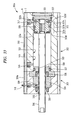
- FIG. 27 is a perspective view showing a pneumatic cylinder according to a tenth embodiment of the present invention
- FIG. 28 is an exploded perspective view of FIG. 27
- FIG. 29 is a partially-omitted vertical cross-sectional view showing the rodless cylinder shown in FIGs. 27 and 28
- FIG. 30 is a transverse cross-sectional view of FIG. 29 .
- members and shapes used in common with the pneumatic cylinder unit shown in FIG. 16 are denoted by the same reference numerals.
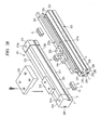
- This pneumatic cylinder unit 201 has a rodless cylinder 211 and a linear guide 212 serving as an attachment connected thereto, i.e., a guide member.
- the rodless cylinder 211 is a slit type and, as shown in FIG. 29 , has a cylinder tube whose outer circumferential shape in transverse section is a quadrangle, i.e., a casing 213, and end covers 214 and 215 are attached to both ends thereof.
- Two pistons 217 and 218 are attached to a circular-transverse-sectional cylinder chamber 216 formed in the casing 213 so as to reciprocate axially, and these pistons 217 and 218 are connected by a piston yoke 219.
- a pneumatic chamber 221 is formed between the end cover 214 and the piston 217.
- a feed/discharge port 214a communicating with the pneumatic chamber 221 and formed in the end cover 214, the pistons 217 and 218 and the piston yoke 219 are driven rightward in FIG. 29 .
- a feed/discharge port 215a is formed in the end cover 215 so as to communicate with a pneumatic chamber 222 formed between the end cover 215 and the piston 218.
- the piston yoke 219 includes, as shown in FIG. 30 , a cylindrical portion 219a in which a notch portion is formed and to both ends of which the pistons 217 and 218 are fixed, and a connecting portion 219b protruding to the outside of the casing through a slit 224 formed in a reciprocation guide surface 223 of the casing 213, wherein a reciprocating body 225 sliding along the reciprocation guide surface 223 of the casing 213 is attached to the connecting portion 219b.
- an inner sealing band 226 is fixed to both ends of the casing 213 and the inner sealing band 226 passes through an interior of the cylindrical portion 219a of the piston yoke 219.
- an outer sealing band 227 is fixed to both ends of the casing 213, and the outer sealing band 227 contacts with an outer surface of the piston yoke 219.
- a T-slot 229 having the communication groove 6 and the engagement groove 7 is formed in whole and in a longitudinal direction on each of two mutually-opposing side faces 228 of the casing 213, each of which forms a right angle with respect to the reciprocation guide surface 223, thereby linearly extending along each side face 228.
- the linear guide 212 connected to such a slit-type rodless cylinder 211 has a rod-like attachment member 231 whose outer shape in transverse section is quadrate, wherein a guide rail 233 is attached to an attachment surface 232 of the attachment member 231 by unshown screw members penetrating attachment holes formed therein.
- sliders 234 are slidably mounted on the guide rail 233, and the sliders 234 and the reciprocating body 225 are provided with a reciprocating table 235 for connecting them. Therefore, when the pistons 217 and 218 are driven by feeding the compressed air to the pneumatic chambers 221 and 222, the reciprocating table 235 moves in a straight-line direction and its movement is guided by the guide rail 233.
- T-shaped slots 239 are formed in whole and in the longitudinal direction on the attachment surface 232 and other three side faces 236 of the attachment member 231, thereby being linearly extending along the attachment surface 232 and the side faces 236, respectively.
- a rod-like spacer 237 is assembled into the T-shaped slot 239 formed in the attachment surface 232 and screw holes 237a, through which the screw members for attaching the guide rail 233 to the attachment member 231 pass, are formed in the spacer 237.
- the T-shaped slots 239 may be formed only in other three side faces 236 without forming the T-shaped slot 39 in the attachment surface 32. In this case, female screw holes may be directly provided on the attachment surface 232.
- the casing 213 of the rodless cylinder 211 and the attachment member 231 of the linear guide 212 are connected, in a state in which the side faces 228 and 236 serving as connection surfaces are opposed to each other, by the insertion fasteners 8 to be embedded in the T-shaped slots 229 and 239 formed in the respective connection surfaces.
- Three insertion fasteners 8 are embedded in both ends and a longitudinal-directional intermediate position of the T-shaped slots 229 and 239.
- the T-shaped slot 229 is formed on each of the two mutually-parallel connection surfaces, i.e., the side faces 228 of the casing 213, so that the linear guide 212 may be connected to any of the above surfaces or faces.
- the above-described pneumatic cylinder unit 201 of the present embodiment which is one obtained by fastening the attachment to the casing 213 of the rodless cylinder 211, has a fastening structure suitable for saving the installation spaces similarly to the above-described first embodiment and is constituted so that rigidity is improved.
- the linear guide 212 is attached as an attachment, the reciprocating body 225 can be moved with high accuracy when the reciprocating body 225 driven by the rodless cylinder 211 is guided by the linear guide 212.
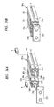
- FIG. 31 is a perspective view showing a modification example of the above-described pneumatic cylinder unit 201 according to the tenth embodiment.
- the linear guides 212 are disposed respectively on both sides of one rodless cylinder 211, and they are directly fastened by the insertion fasteners 8, which are embedded in the respective T-shaped slots 229 and 239, similarly to the pneumatic cylinder unit 201 shown in FIG. 27 . Therefore, a reciprocating table 235a attached to the reciprocating body 225 can be linearly reciprocated with higher accuracy since guided by two guide rails 233 on both sides.
- two rodless cylinders 211 in which the two rodless cylinders 211 are directly fastened using the insertion fasteners 8 may be formed.
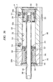
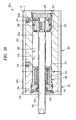
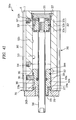
- FIG. 32 is a perspective view of an entirety of a pneumatic cylinder used in a pneumatic cylinder unit according to an eleventh embodiment of the present invention, wherein FIG. 32A is a perspective view showing an exploded state before assembling and FIG. 32B is a perspective view showing an assembled state.
- FIG. 33 is an axial-directional cross-sectional view taken along line A-A of the assembled pneumatic cylinder of FIG. 32B .
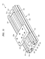
- the pneumatic cylinder 301a in an exploded state before assembling includes a rod cover 303 for discharging dusts and a basic cylinder 302, as individual assembly parts.
- the basic cylinder 302 has a cylinder tube 305, whose both axial-directional end faces 304 are substantially square and whose entirety has an axially long cuboid shape, and is provided with a piston rod 306 protruding from a center of one of the end faces (end face 304 on a front side of the Figures).
- screw holes 307 are formed at four corners of the same end face. Note that although the end faces 304 of the basic cylinder 302 are substantially square, they may be rectangular and the screw holes 307 may be formed not at the four corners of the end face but at two corners on a diagonal line thereof.
- the rod cover 303 for discharging dusts has a rod cover 309a formed into a cuboid whose end face 308 has the same shape as that of the cylinder tube 305, and a later-described functional component is provided to an interior thereof.
- a rod through hole into which the piston rod 306 can be inserted and a bolt through hole 312 into which a bolt 311 can be inserted are formed at a central position of the end face 308 and at each of the four corners or two corners on a diagonal line of the end face 308, respectively, so as to penetrate axially the rod cover 309a.
- the pneumatic cylinder 301a as shown in FIG. 32B is assembled integrally.
- the communication groove 6 opened so as to extend linearly through the length in an axial direction and the engagement groove 7 communicating with it are formed.
- Feed/discharge ports 316 and 317 for feeding and discharging compressed air are formed at two locations overlapping the communication groove 6 in one side face of the cylinder tube 305.
- a dust outlet 318 serving as an air discharge port is formed at one location overlapping the communication groove 6 on one side face of the rod cover 309a.
- a piston accommodating hole 319 is formed axially in an interior of the cylinder tube 305.
- a packing case 320 with which the rod cover 303 for discharging dusts is provided is fitted in an opening on a side on which the piston rod 306 protrudes.
- a head cover 321 is provided at an end of the cylinder tube 305 located on an opposite side thereof.
- a space formed between the packing case 320 and the head cover 321 of the piston accommodating hole 319 constitutes a cylinder chamber 322.
- a piston 323 is attached to an interior of the cylinder chamber 322 so as to be reciprocable axially, and the piston 323 divides the interior of the cylinder chamber 322 into a fluid pressure chamber 322a for retraction and a fluid pressure chamber 322b for extension.
- a rod bush 324 employing an oil-impregnated copper alloy as its material is provided in the rod cover 309a, and the piston rod 306 fixed to an end face of the piston 323 penetrates the packing case 320 and the rod bush 324 and slidably protrudes from the rod through hole 310.
- the piston 323 is formed into a substantially cylindrical shape, wherein an outer diameter of an extension-side end 323a and a retraction-side end 323c thereof is slightly smaller than that of a slide-intermediate portion 323b therebetween and the slide-intermediate portion 323b is fitted in and slidably contacts with the piston accommodating hole 319 and the extension-side end 323a and the retraction-side end 323c form gaps with an inner circumferential surface of the piston accommodating hole 319.
- a wear ring 323d is attached to each outer periphery of the extension-side end 323a and the retraction-side end 323c so as to sandwich front and rear parts of the slide-intermediate portion 323b.
- wear rings 323d are capable of reserving and maintaining the communication with the fluid pressure chamber 322a for retraction and the fluid pressure chamber 322b for extension without blocking the feed/discharge ports 316 and 317 even when each of the feed/discharge ports 316 and 317 coincides with the axial-directional position thereof in spite of slidably contacting with the piston housing hole 319.
- the piston 323 is at an extension-side stroke end position in a state in which its extension-side end face contacts with the retraction-side end face of the packing case 320, and is at a retraction-side stroke end position in a state in which the retraction-side end face of the piston 323 contacts with the extension-side end face of the head cover 321.
- the feed/discharge port 316 communicating with the fluid pressure chamber 322a for retraction is disposed at the same axial-directional position as that of the small-diameter extension-side end face 323a, so that the feed/discharge port 316 is not blocked by the slide-intermediate portion 323b of the piston 323 and the communication with the fluid pressure chamber 322a for retraction can be always ensured.
- the feed/discharge port 317 communicating with the fluid pressure chamber 322b for extension is disposed at the same axial-directional position as that of the small-diameter retraction-side end face 323c, so that the feed/discharge port 317 is not blocked by the slide-intermediate portion 323b of the piston 323 and the communication with the fluid pressure chamber 322b for extension can be always ensured.
- Packings 326 slidably contacting with the piston rods 306 are provided in a through hole 325 of the packing case 320 and a rod through hole 310 of the rod cover 309a.
- O rings 327 are provided on outer peripheries of the packing case 320 and the head cover 321, and a seal ring 328 is provided on an outer periphery of the slide-intermediate portion 323b of the piston 323.
- a dust passage 329 communicating with an outer circumferential surface of the piston rod 306 at the position near the packing 326 which is attached to the rod through hole 310 is formed, and this dust passage 329 communicates with the dust outlet 318 of the rod cover 309a so that these constitute altogether a discharge passage.
- This discharge passage is a functional component provided in the rod cover 303 for discharging dusts. When an unshown air suction device etc. is connected to the discharge passage, dusts generated by slidable contact between the piston rod 306 and the packing 326 can be discharged through this discharge passage.
- the pneumatic cylinder 301a employed in this embodiment serves as a double-acting pneumatic cylinder for driving an object to be driven by controlling a supply of the compressed air to each of the two feed/discharge ports 316 and 317 so as to reciprocate the piston rod 306 in the straight-line direction, and has a structure suitable for use in a process which requires high cleanliness, such as a semiconductor manufacturing line, since the dusts generated by linear reciprocation of the piston rod 306 are not emitted to an outer surrounding area.
- the rod cover 303 for discharging dusts which is provided with the discharge passage serving as a functional component, can be attached to and detached from the basic cylinder 302 and arbitrarily replaced, so that even if failure occurs in either the dust discharge function of the rod cover 303 for discharging dusts or the rod drive function of the basic cylinder 302, this structure has high resource efficiency since the one in which the failure occurs has only to be replaced without changing the entirety.
- FIG. 34 is a perspective view of an entirety of a pneumatic cylinder unit of the present embodiment formed by fastening two pneumatic cylinders 301a, wherein FIG. 34A is a perspective view showing an exploded state before assembling and FIG. 34B is a perspective view showing an assembled state.
- the respective piston rods 306 are arranged parallel in the same direction, the cylinder tubes 305 and the rod covers 309a are made to contact with each other by side faces 313c and fastened via the insertion fasteners 8, and a common tip plate 332 serving as a linking member for mutually connecting both piston rods 306 is attached to the tips of the piston rods 306 thereof, whereby a twin-rod cylinder is constituted.
- this tip plate 332 drives the piston rods 306 in the straight-line direction, thereby driving the object to be driven in the straight-line direction by a tip face of the tip plate 332.
- the two cylinder tubes 305 to be fastened are mutually serving as attachments.
- the pneumatic cylinder which constitutes the above-mentioned pneumatic cylinder unit and to which the rod cover with a functional component is attachably and detachably provided, will include the following examples.
- FIG. 35 is a perspective view of an entirety of a pneumatic cylinder 301b used in a pneumatic cylinder unit according to a twelfth embodiment of the present invention, wherein FIG. 35A is a perspective view showing an exploded state before assembling and FIG. 35B is a perspective view showing an assembled state.
- FIG. 36 is an axial-directional cross-sectional view taken along line B-B of the pneumatic cylinder 301b assembled in FIG. 35B .
- members and shapes common with the pneumatic cylinder 301a shown in FIGs. 32 and 33 are denoted by the same reference numerals.
- the pneumatic cylinder 301b in an exploded state before assembling has a rod cover 341 for oil-impregnated bearing which is provided with a later-described oil-impregnated bearing in an interior of a rod cover 309b, and the basic cylinder 302, as individual assembly parts.
- a rod through hole 342 through which the piston rod 306 can penetrate is formed at a center of the end face 308 of the rod cover 309b, so that by inserting the piston rod 306 into the rod through hole 342 and being fastened by four bolts 311 in a state in which the basic cylinder 302 and the rod cover 309b are made to serially contact with each other, the pneumatic cylinder 301b such as that shown in FIG. 35B is assembled integrally.
- a housing 343 provided with the rod cover 341 for oil-impregnated bearing is fitted in an opening of the piston accommodating hole 319 on a side on which the piston rod 306 protrudes, whereby a space formed between the housing 343 of the piston accommodating hole 319 and the head cover 321 is forming the cylinder chamber 322.
- the housing 343 is secured and installed in the interior of the rod cover 309b by a seal holder 344 and a snap ring 345, whereby the piston rod 306 penetrates the housing 343 so as to slidably protrude from the rod cover 309b.
- the piston 323 is at the extension-side stroke end position in a state in which the extension-side end face thereof contacts with the retraction-side end face of the housing 343.
- the oil-impregnated bearing 346 to which lubricating oil is impregnated is provided at a portion contacting with the outer circumferential surface of the piston rod 306 in the interior of the housing 343, and the oil-impregnated bearing 346 constitutes a functional component provided in the rod cover 341 for oil-impregnated bearing. Since this oil-impregnated bearing 346 contacts slidably with and supports the piston rod 306, the piston rod 306 can be smoothly slid while maintaining the airtightness of the cylinder chamber 322.
- the pneumatic cylinder 301b employed in the present embodiment serves as a double-acting pneumatic cylinder, and has a structure in which the piston rod 306 can be driven with high efficiency with respect to supply pressure and supply amount of compressed air.
- FIG. 37 is a perspective view of an entirety of a pneumatic cylinder 301c used in a pneumatic cylinder unit according to a thirteenth embodiment of the present invention, wherein FIG. 37A is a perspective view showing an exploded state before assembling and FIG. 37B is a perspective view showing an assembled state.
- FIG. 38 is an axial-directional cross-sectional view taken along line C-C of the pneumatic cylinder 301c assembled in FIG. 37B .
- members and shapes common with the pneumatic cylinder 301a shown in FIGs. 32 and FIG. 33 are denoted by the same reference numerals.
- the pneumatic cylinder 301c which is in an exploded state before assembling has a ball-bearing rod cover 351 provided with a later-described ball bearing in the interior of the rod cover 309c, and the basic cylinder 302, as individual assembly parts.
- a rod through hole 352, through which the piston rod 306 can penetrate, is formed at a center of the end face 308 of the rod cover 309c, so that by inserting the piston rod 306 into the rod through hole 352 and being fastened by four bolts 311 in a state in which the basic cylinder 302 and the rod cover 309c are made to contact with each other, the pneumatic cylinder 301c such as that shown in FIG. 37B is assembled integrally.
- a sleeve 353 with which the ball-bearing rod cover 351 is provided is fitted in an opening of the piston housing hole 319 on the extension side of the piston rod 306, whereby a space formed between the sleeve 353 of the piston accommodating hole 319 and the head cover 321 constitutes the cylinder chamber 322.
- the sleeve 353 is secured and installed in an interior of the rod cover 309c by a housing 354 for the packing 326, a seal holder 355, and a snap ring 356.
- the piston rod 306 penetrates the sleeve 353 and the housing 354 so as to slidably protrude from the rod cover 309c.
- the piston 323 is at the extension-side stroke end position in a state in which the extension-side end face thereof contacts with the retraction-side end face of the sleeve 353.
- a large number of balls 357 contacting with the outer circumferential surface of the piston rod 306 for guiding the axial-directional movement of the piston rod 306 are installed in the sleeve 353, and a ball bearing 358 housing these balls 357 forms the sleeve 353, whereby a functional component provided in the ball-bearing rod cover 351 is constituted. Since the ball bearing 358 supports the piston rod 306, the piston rod 306 can be smoothly slid while certainly supported also with respect to a lateral direction.
- the pneumatic cylinder 301c employed in the present embodiment serves as a double-acting pneumatic cylinder, and has a structure in which the piston rod 306 can be smoothly reciprocated while a large lateral load applied thereon is tolerated.
- FIG. 39 is a perspective view of an entirety of a pneumatic cylinder 301d used in a pneumatic cylinder unit according to a fourteenth embodiment of the present invention, wherein FIG. 39A is a perspective view showing an exploded state before assembling and FIG. 39B is a perspective view showing an assembled state.
- FIG. 40 is an axial-directional cross-sectional view taken along line D-D of the pneumatic cylinder 301d assembled in FIG. 39B , wherein FIG. 40A is a cross-sectional view showing a state in which a movable stopper is at an extendable limit position and FIG. 40B is a cross-sectional view showing a state in which the movable stopper is at a retractable limit position.
- members and shapes common with the pneumatic cylinder 301a shown in FIGs. 32 and 33 are denoted by the same reference numerals.
- the pneumatic cylinder 301d which is in an exploded state before assembling, has a rod cover 361 for stroke adjustment which is provided with a later-described movable stopper in an interior of the rod cover 309d, and the basic cylinder 302, as individual assembly parts.
- a rotating knob 362a with a shape of a circular plate is attached to a central position of the end face 308 of the rod cover 309d and further a rod through hole 363, through which the piston rod 306 can penetrate, is formed at the central position.
- the pneumatic cylinder 301d such as that shown in FIG. 39B is assembled integrally.
- the movable stopper 364a As shown in FIG. 40 , the movable stopper 364a, with which the rod cover 361 for stroke adjustment is provided, is fitted in the opening of the piston accommodating hole 319 on a side on which the piston rod 306 protrudes, and a space formed between the movable stopper 364a of the piston accommodating hole 319 and the head cover 321 constitute the cylinder chamber 322.
- a stopper accommodating hole 365a which is concentric with and has the same diameter as that of the piston accommodating hole 319, is formed in the rod cover 309d, and the movable stopper 364a is screwed in a female screw 366 formed on an extension-side inner periphery of the stopper accommodating hole 365.
- the movable stopper 364a is screwed so as to axially move forward or backward.
- the piston 323 is at the extension-side stroke end position in a state in which the extension-side end face thereof contacts with the retraction-side end face of the movable stopper 364a, and is at the retraction-side stroke end position in a state in which the retraction-side end face of the piston 323 contacts with the extension-side end face of the head cover 321.
- a retention groove 367 is formed along a circle disposed on an slightly outer circumferential side of and being concentric with the opening of the stopper accommodating hole 365a, and further a securing groove 368 is formed in a side wall on the outer circumferential side.
- a cylindrical portion 369b On the retraction-side end face of the rotating knob 362a, a cylindrical portion 369b whose tip is provided with a flange 369a capable of being fitted in the retention groove 367 is formed. Since a snap ring 370 is fitted into an outer periphery of the cylindrical portion 369b and the cylindrical portion 369b is press-inserted into the retention groove 367, the snap ring 370 is engaged with the securing groove 368 therein and the entirety of the rotating knob 362a is rotatably attached to the rod cover 309d.
- the piston rod 306 penetrates the movable stopper 364a and the rotating knob 362a and slidably protrudes from the rod cover 309d.
- rotation transmission pins 371 are provided so as to protrude at two positions around the rod through hole 363 regarded as the center, and rotation transmission holes 372 are formed at two positions corresponding to the extension-side end face of the movable stopper 364a so that the respective rotation transmission pins 371 are slidably inserted therein.
- a screw hole 373 is formed at the same axial-directional position as that of the extension-side end thereof on an upper surface of the rod cover 309d in the Figure, and a stopper setscrew 374 is screw-connected to an interior thereof.
- the feed/discharge port 316 communicating with the fluid pressure chamber 322a for retraction is disposed at the same axial-directional position as that of a chamfered portion 375 formed on the outer periphery of the retraction-side end face thereof, whereby even when the movable stopper 364a is at the retractable limit position, the communication from the feed/discharge port 316 to the fluid pressure chamber 322a for retraction is ensured.
- An axial-directional length "Z" of the extension-side end 323a of the piston 323 with a small diameter is almost equal to a movable length "Y" (stroke adjustment width) of the movable stopper 364a, so that even when the movable stopper 364a is at the extendable limit position and the piston 323 is at the extension-side stroke end position, the feed/discharge port 316 is not blocked by the slide-intermediate portion 323b of the piston 323 and the communication with the fluid pressure chamber 322a for retraction is always ensured.
- the O ring 327 is provided on the outer periphery of the movable stopper 364a, and the packing 326 is provided in a through hole 376 of the movable stopper 364a.
- the movable stopper 364a contacts with the piston 323 so as to constitute a stopper for restricting the stroke end position of the piston 323, the rotating knob 362a and the rotation transmission pin 371 constitute a position adjustment member for adjusting the position of the movable stopper 364a, and the entire mechanism in the rod cover 361 for stroke adjustment including those described above constitute an assembly for stroke adjustment serving as a functional component.
- the rotating knob 4 When the rotating knob 4 is rotated in this state, the movable stopper 364a is also rotated via the two rotation transmission pins 371 and, as a result, the movable stopper 364a is screwed so as to move backward.
- the rotation transmission pins 371 fixed to the rotating knob 362a maintain states of slidably contacting with and being inserted into the rotation transmission holes 372 of the movable stopper 364a. Therefore, the rotating knob 362a keeps transmitting the rotation to the movable stopper 364a.
- the pneumatic cylinder 301d employed in the present embodiment serves as a double-acting pneumatic cylinder, wherein the extension-side stroke end position and the movement stroke of the piston 323 can be adjusted by rotating the rotating knob 362a and changing the axial-directional position of the movable stopper 364a.
- the total length of the fixed portions which includes the rotating knob 362a, the rod cover 309d, and the cylinder tube 305, is not changed and therefore can be installed even in an axially narrow space.
- the movable stopper 364a can be fixed by tightening the stopper setscrew 374.
- FIG. 41 is an axial-directional cross-sectional view of a pneumatic cylinder 301e provided with a modification example of the above-described rod cover for stroke adjustment 361.
- members common with the pneumatic cylinder 301d shown in FIG. 40 are denoted by the same reference numerals.
- a securing groove 377 is formed in an extension-side inner periphery of a stopper accommodating hole 365b.
- a cylindrical portion 378a which can be fitted into the stopper accommodating hole 365b is formed in a retraction-side end face of a rotating knob 362b.
- the snap ring 370 When the snap ring 370 is fitted into a securing groove 378b formed in the outer periphery of the cylindrical portion 378a and the cylindrical portion 378a is press-inserted into the stopper accommodating hole 365b, the snap ring 370 is engaged with both the securing groove 378b in a side of the cylindrical portion 378a and the securing groove 377 in a side of the stopper accommodating hole 365b, whereby the entirety of the rotating knob 362b is rotatably attached to a rod cover 309e.
- a female screw 379 with a diameter larger than that of the piston rod 306 is formed in a center of the rotating knob 362b, whereby an extension-side part of the movable stopper 364b is screw-connected to the interior thereof and a retraction-side part thereof is slidably attached to the piston accommodating hole 319 and the stopper accommodating hole 365b.
- a rotation prevention groove 380 is axially formed on an upper side face of the movable stopper 364b in the Figure, and a stopper setscrew 382 serving as a rotation prevention member is screw-connected to a screw hole 381 formed in an upper end face of the rod cover 309e in the Figure so as to be engaged with the rotation prevention groove 380.
- the movable stopper 364b can move only axially without being rotated about the axis due to the engagement with the stopper setscrew 382 and therefore, by rotating the rotating knob 362b, can be certainly screwed so as to axially move forward or backward.
- the extension-side stroke end position and the movement stroke of the piston 323 can be adjusted by changing the axial-directional position of the movable stopper 364b.
- the movable stopper 364b can be fixed by tightening the stopper setscrew 382.
- the pneumatic cylinders 301a to 301e have highly versatile structures capable of corresponding to various applications are provided, since the rod covers 309a to 309e equipped with functional components corresponding to use applications can be selectively attached to the basic cylinder 302 provided in common as a main driving unit. Accordingly, also in terms of designing and manufacturing, the functional components which are prepared in many types depending on the use applications can be provided as component parts which are independent from driving performance of the basic cylinder 302. Therefore, there is obtained also advantage of being capable of avoiding multiplication of types of product cylinders by virtue of such a combination and simplifying production management.
- the present invention is not limited to the above-described embodiments and can be variously modified without departing from the gist thereof.
- the above-described embodiments have shown only the case where the sectional shapes of the engagement grooves 7 and the engaging pieces 11 are formed to be rectangular, they are not limited thereto as long as each of them is formed to have a width larger than the opening width "Wo" of the communication groove 6 and the fastening surfaces 15 and the engagement surfaces 9 contact certainly with each other.
- they may have a polygonal shape as shown in FIG. 42 or a half circular shape as shown in FIG. 43 .
- fastening surfaces 15 and the engagement surfaces 9 can certainly face-contact with each other, these are not limited to that formed to be parallel with the connection surfaces 3c.
- they may be formed to be inclined with respect to the connection surfaces 3c as shown in FIG. 44 .
- the communication groove 6 and the engagement groove 7 do not require being formed throughout the entire length in the longitudinal direction of the member to be fastened, and may be cut at a middle position, bent at a middle position, curved in whole, or formed partially at a middle position of the connection surface.
- the intermediate fasteners 71 and 73 as shown in FIGs. 12 and 13 , which can be installed at the longitudinal-directional intermediate position, can be suitably utilized.
- fasteners in the fastening assemblies of the above-described second to sixth embodiments are formed as metal-fittings which are metal-made molded products, they may be resin-made molded products.
- the number thereof to be fastened can be arbitrarily set by being increased or reduced as required, and the tip plates may be also arbitrarily formed and installed according to the number and arrangement of rods.
- rodless cylinder 211 employed in the pneumatic cylinder unit of the tenth embodiment is a slit type
- another type of rodless cylinder such as a magnetic type can be also applied.
- the functional components comprise the dust discharging channel, the oil-impregnated bearing, the ball bearing, and the assembly for stroke adjustment in the pneumatic cylinders employed in the pneumatic cylinder units of the above-described eleventh to fourteenth embodiments have been described, structures other than these can be applied to the functional components.
- the pneumatic cylinders employing the compressed air as the working fluid are shown as examples of the fluid pressure cylinder, but the present invention is not limited thereto and, for example, can be applied to that employing a liquid as working fluid such as oil hydraulic.
- the fastening assembly and the fastener according to the present invention can be applied to any fastening structure in which the respective surfaces of two members are made to contact with each other and fastened therebetween, and particularly are useful in application to the cases where easy and reliable fastening is required and where space saving is required in a fastened state and to a fastening structure in which arbitrary and easy setting and change of the relative arrangement between the two members and the fastening position are required.
- the fluid pressure cylinder unit according to the present invention is particularly useful in the case where space saving is required and, at the same time, an attachment etc. has to be fastened in order to realize enhancement of rigidity and highly accurate reciprocation, such as an actuator employed in a device for conveying electronic components such as semiconductor chips.
Landscapes
- Engineering & Computer Science (AREA)
- General Engineering & Computer Science (AREA)
- Mechanical Engineering (AREA)
- Physics & Mathematics (AREA)
- Fluid Mechanics (AREA)
- Actuator (AREA)
Claims (22)
- Schräges teilendes Metall-Anschlussteil (57) zum Verbinden zweier Blöcke (1a, 1 b), von welchen jeder Verbindungsoberflächen (3c), Kommunikationsnuten (6), die sich in einer Längsrichtung entlang jeder der Verbindungsoberflächen (3c) erstrecken und geöffnet sind, und Eingriffsnuten (7), die mit einer Eingriffsoberfläche (9) parallel zu jeder der Verbindungsoberflächen (3c) versehen sind und mit der Kommunikationsnut (6) kommunizieren, wobei das schräge teilende Metall-Anschlussteil (57) dadurch gekennzeichnet ist, dass es folgendes aufweist:ein erstes Eingriffsstück (11), das integral mit einem ersten Verbindungsbereich (62a) versehen ist und eine Befestigungsoberfläche (15) hat, die breiter als der erste Verbindungsbereich (62a) ist und in einer Längsrichtung ausgebildet ist, und eine Stirnfläche (59a), die derart ausgebildet ist, dass sie an ihrer Spitze schräg ist;ein zweites Eingriffsstück (11), das integral mit einem zweiten Verbindungsbereich versehen ist und eine Befestigungsoberfläche (15) hat, die breiter als der zweite Verbindungsbereich (62b) ist und in der Längsrichtung von und wechselseitig entgegengesetzt zu der Befestigungsoberfläche (15) verschoben ist und in der Längsrichtung ausgebildet ist, wobei das zweite Eingriffsstück (11) eine Stirnfläche (59b) hat, die an der Stirnfläche (59a) des ersten Eingriffsstücks (11) angrenzt und derart ausgebildet ist, dass sie an ihrer Spitze schräg ist; undein Schraubenelement (53), das mit einem Schraubenloch (61) schraubverbunden ist, das in einem der Eingriffsstücke (11) ausgebildet ist, ein Durchgangsloch (60) durchdringt, das in dem anderen der Eingriffsstücke (11) mit einem Durchmesser ausgebildet ist, der größer als derjenige des Schraubenlochs (61) ist, und veranlasst, dass sich die Eingriffsstücke (11) entlang der Stirnfläche (59a, 59b) in einer Richtung bewegen, in welcher sich die jeweiligen Befestigungsoberflächen (15) einander nähern.
- Fluiddruckzylindereinheit zum derartigen Antreiben eines Objekts, dass es durch Fluiddruck in einer geradlinigen Richtung angetrieben wird, wobei die Einheit folgendes aufweist:das schräge teilende Metall-Anschlussteil nach Anspruch 1;ein Zylinderrohr (102, 305), in welchem eine Kommunikationsnut (6), die sich in einer Längsrichtung entlang einer Verbindungsoberfläche (105c) erstreckt und geöffnet ist, und eine Eingriffsnut (7), die mit einer Eingriffsoberfläche parallel zu der Verbindungsoberfläche versehen ist und mit der Kommunikationsnut (6) kommuniziert, ausgebildet sind und ein mit einer Kolbenstange (104, 306) versehener Kolben (323) axial und hin- und herbewegbar untergebracht ist; undein Anbauteil (102, 212), in welchem eine Kommunikationsnut (6), die sich in der Längsrichtung entlang einer Verbindungsoberfläche (105c) erstreckt und geöffnet ist, die mit der Verbindungsoberfläche in Kontakt ist, und eine Eingriffsnut (7), die mit einer Eingriffsoberfläche parallel zu der Verbindungsoberfläche versehen ist und mit der Kommunikationsnut (6) kommuniziert, ausgebildet sind,wobei in einem Zustand, in welchem die Kommunikationsnuten (6) entgegengesetzt zueinander sind und veranlasst ist, dass das Zylinderrohr (102) und das Anbauteil (102) durch die Verbindungsoberflächen in Kontakt sind, das erste Eingriffsstück (11) des schrägen teilenden Metall-Anschlussteils (57) in die Eingriffsnut (7) des Zylinderrohrs (102) in der Längsrichtung eingefügt ist und das zweite Eingriffsstück (11) des schrägen teilenden Metall-Anschlussteils (57) in die Eingriffsnut (7) das Anbauteils (102) in der Längsrichtung eingefügt ist, undwobei dann, wenn das schräge teilende Metall-Anschlussteil (57) in dem Zylinderrohr (102) und dem Anbauteil (102) eingebettet ist und die Eingriffsoberflächen und die Befestigungsoberflächen einander kontaktieren, das Zylinderohr und das Anbauteil verbunden sind.
- Fluiddruckzylindereinheit nach Anspruch 2, wobei ein transversaler Abschnitt des Zylinderrohrs (102) ein Viereck ist und jeweilige wechselseitig benachbarte äußere Umfangsoberflächen davon als Verbindungsoberflächen dienen, in welchen die Kommunikationsnuten (6) ausgebildet sind.
- Fluiddruckzylindereinheit nach Anspruch 2 oder 3, wobei das Anbauteil (102) ein Zylinderrohr gleich dem Zylinderrohr (102) ist.
- Fluiddruckzylindereinheit nach Anspruch 4, wobei eine Kolbenstange (104) des Zylinderrohrs (102) und eine Kolbenstange (104) des Anbauteils (102) durch ein Verbindungselement (107a) verbunden sind.
- Fluiddruckzylindereinheit nach Anspruch 4, wobei die zwei Zylinderrohre (102) so befestigt sind, dass ihre jeweiligen Kolbenstangen (104) umgekehrt zueinander gerichtet sind, und ein Spannfutterelement (117) an jedem der Kolbenstangen angebracht ist.
- Fluiddruckzylindereinheit nach Anspruch 4, wobei eine Führungsschiene (121) an jedem der Zylinderrohre (102) angebracht ist und ein an einem Gleitkörper angebrachter Gleittisch (123a), der entlang der Führungsschiene gleitet, an jeder der Kolbenstangen (104) angebracht ist.
- Fluiddruckzylindereinheit nach Anspruch 2 oder 3, wobei das Anbauteil (102) als Führungsblock (116) zum axialen, hin- und herbewegbaren Unterbringen einer Führungsstange (115) dient und die Führungsstange und die Kolbenstange (115) durch ein Verbindungselement verbunden sind.
- Fluiddruckzylindereinheit nach Anspruch 8, wobei jeweils eine Vielzahl der Zylinderrohre (102) und ein Vielzahl der Anbauteile (102) befestigt sind.
- Fluiddruckzylindereinheit, die eine stangenlosen Zylinder (211) zum Antreiben eines sich hin- und herbewegbaren Körpers (225) in einer geradlinigen Richtung durch Fluiddruck verwendet, wobei die Einheit folgendes aufweist:das schräge teilende Metall-Anschlussteil nach Anspruch 1;ein Gehäuse (213) des stangenlosen Zylinders, in welchem ein Kolben (217, 218), der durch den Fluiddruck in der geradlinigen Richtung hin-. und herbewegt wird und mit dem sich hin- und herbewegbaren Körper (225) verbunden ist, eingebaut ist und in welchem eine Kommunikationsnut (6), die sich entlang einer Verbindungsoberfläche (105c) erstreckt und geöffnet ist, die an einem äußeren Umfang ausgebildet ist, und eine Eingriffsnut (7), die mit der Kommunikationsnut (6) kommuniziert und breiter als die Kommunikationsnut ist, ausgebildet sind; undein Anbauteil (212), in welchem eine Kommunikationsnut (6), die sich entlang einer Verbindungsoberfläche erstreckt und geöffnet ist, die mit der Verbindungsoberfläche in Kontakt ist, und eine Eingriffsnut (7), die mit der Kommunikationsnut kommuniziert und breiter als die Kommunikationsnut ist, ausgebildet sind,wobei in einem Zustand, in welchem die jeweiligen Kommunikationsnuten (6) entgegengesetzt zueinander sind und das Gehäuse (213) und das Anbauteil (212) veranlasst sind, sich jeweils durch die Verbindungsoberflächen zu kontaktieren, das erste Eingriffsstück (11) des schrägen teilenden Metall-Anschlussteils (57) in die Eingriffsnut des Gehäuses in einer Längsrichtung eingefügt ist und das zweite Eingriffsstück (11) des schrägen teilenden Metall-Anschlussteils (57) in die Eingriffsnut das Anbauteils in der Längsrichtung eingefügt ist
- Fluiddruckzylindereinheit nach Anspruch 10, wobei das Schraubenelement (53) des schrägen teilenden Metall-Anschlussteils (57) über das schräge teilende Metall-Anschlussteil eine Befestigungskraft auf das Gehäuse (213) und das Anbauteil (212) ausübt.
- Fluiddruckzylindereinheit nach Anspruch 10 oder 11, die weiterhin folgendes aufweist:eine Kolbengabel (219), die durch einen in einer in dem Gehäuse (213) ausgebildeten Hinundherbewegungsführungsoberfläche (223) ausgebildeten Schlitz (214) von der Hinundherbewegungsführungsoberfläche nach außen vorsteht und den Kolben (217, 218) und den sich hin- und herbewegenden Körper (225) verbindet;ein inneres Dichtungsband (226), das an beiden Enden des Gehäuses fixiert ist und den Schlitz von innen abdichtet; undein äußeres Dichtungsband (227), das an den beiden Enden des Gehäuses fixiert ist und den Schlitz von außen abdichtet.
- Fluiddruckzylindereinheit nach einem der Ansprüche 10 bis 12, wobei das Anbauteil (212) ein Führungselement ist, das mit einer Schiene (233) zum Führen eines sich hin- und herbewegenden Tischs (235) versehen ist.
- Fluiddruckzylindereinheit nach Anspruch 13, wobei Führungselemente an beiden Seiten des Gehäuses (213) des stangenlosen Zylinders (211) befestigt sind.
- Fluiddruckzylindereinheit nach einem der Ansprüche 10 bis 12, wobei das Anbauteil (212) ein Gehäuse eines stangenlosen Zylinders von demselben Typ wie demjenigen des Gehäuses (213) ist.
- Fluiddruckzylindereinheit nach Anspruch 2, die weiterhin folgendes aufweist:die Kolbenstange (306), die an dem Kolben (323) angebracht ist und von einer Endfläche de Zylinderrohrs (305) nach außen vorsteht; undeine Stangenabdeckung (309a), die anbringbar und loslösbar an der Endfläche des Zylinderrohrs angebracht ist und mit einer funktionellen Komponente versehen ist, die einen funktionellen Effekt gemäß einer Einsatzanwendung zeigt.
- Fluiddruckzylindereinheit nach Anspruch 16, wobei die funktionelle Komponente ein Entladungsdurchgang ist, der mit einem in der Stangenabdeckung (309a) ausgebildeten Entladungstor (318) verbunden ist und durch eine lineare Hinundherbewegung des Kolbens in der Fluiddruckzylindereinheit erzeugten Staub nach außen entlädt.
- Fluiddruckzylindereinheit nach Anspruch 16, wobei die funktionelle Komponente ein ölimprägniertes Lager (346) ist, das in der Stangenabdeckung (309a) eingebaut ist und eine äußere Umfangsoberfläche der Kolbenstange (306) kontaktiert.
- Fluiddruckzylindereinheit nach Anspruch 16, wobei die funktionelle Komponente ein lineares Kugellager (358) ist, das in der Stangenabdeckung (309c) eingebaut ist, eine äußere Umfangsoberfläche der Kolbenstange (306) kontaktiert und eine Kugel (357) zum Führen einer Bewegung der Kolbenstange in axialer Richtung hat.
- Fluiddruckzylindereinheit nach einem der Ansprüche 16 bis 19, wobei die funktionelle Komponente eine Anordnung für eine Hubeinstellung ist, welche Anordnung einen Stopper (364) hat, der in der Stangenabdeckung (309d) eingebaut ist und eine Hubendposition des Kolbens (323) durch Kontaktieren des Kolbens beschränkt, und ein Positionseinstellelement (362a, 371), das an der Stangenabdeckung angebracht ist und eine Position des Stoppers einstellt.
- Fluiddruckzylindereinheit nach einem der Ansprüche 16 bis 20, wobei irgendeine einer mit dem Entladungsdurchgang versehenen Stangenabdeckung (303) zum Entladen von Staub, einer mit dem ölimprägnierten Lager versehenen Stangenabdeckung (341) zum ölimprägnierten Lagern, einer mit dem linearen Kugellager versehenen Stangenabdeckung (351) mit linearem Kugellager und einer mit der Anordnung für eine Hubeinstellung versehenen Stangeabdeckung (361) für eine Hubeinstellung an der Endfläche des Zylinderrohrs (305) angebracht sein kann.
- Fluiddruckzylindereinheit nach einem der Ansprüche 16 bis 21, wobei das Schraubenelement (53) des schrägen teilenden Metall-Anschlussteils (57) über das schräge teilende Metall-Anschlussteil eine Befestigungskraft auf das Zylinderrohr und das Anbauteil ausübt.
Applications Claiming Priority (9)
| Application Number | Priority Date | Filing Date | Title |
|---|---|---|---|
| JP2003018985A JP4308539B2 (ja) | 2003-01-28 | 2003-01-28 | 流体圧シリンダ |
| JP2003018983A JP4185373B2 (ja) | 2003-01-28 | 2003-01-28 | 締結組立体および連結具 |
| JP2003018986A JP4308540B2 (ja) | 2003-01-28 | 2003-01-28 | ロッドレスシリンダユニット |
| JP2003018986 | 2003-01-28 | ||
| JP2003018985 | 2003-01-28 | ||
| JP2003018984A JP4308538B2 (ja) | 2003-01-28 | 2003-01-28 | 流体圧シリンダユニット |
| JP2003018984 | 2003-01-28 | ||
| JP2003018983 | 2003-01-28 | ||
| PCT/JP2003/011119 WO2004067972A1 (ja) | 2003-01-28 | 2003-08-29 | 締結組立体、連結具および流体圧シリンダユニット |
Publications (3)
| Publication Number | Publication Date |
|---|---|
| EP1589235A1 EP1589235A1 (de) | 2005-10-26 |
| EP1589235A4 EP1589235A4 (de) | 2006-04-12 |
| EP1589235B1 true EP1589235B1 (de) | 2010-11-17 |
Family
ID=32831018
Family Applications (1)
| Application Number | Title | Priority Date | Filing Date |
|---|---|---|---|
| EP03815606A Expired - Lifetime EP1589235B1 (de) | 2003-01-28 | 2003-08-29 | Befestigter anordnungskörper, verbinder und hydraulikzylindereinheit |
Country Status (4)
| Country | Link |
|---|---|
| US (1) | US7444922B2 (de) |
| EP (1) | EP1589235B1 (de) |
| DE (1) | DE60335031D1 (de) |
| WO (1) | WO2004067972A1 (de) |
Families Citing this family (52)
| Publication number | Priority date | Publication date | Assignee | Title |
|---|---|---|---|---|
| BRPI0404175A (pt) * | 2004-09-27 | 2006-05-09 | Trw Automotive Ltda | cilindro mestre para sistemas de freios de veìculos automotores |
| DE202005003394U1 (de) * | 2005-03-03 | 2005-05-12 | Rk Rose + Krieger Gmbh Verbindungs- Und Positioniersysteme | Profilverbinder |
| DE202006013135U1 (de) * | 2006-08-26 | 2006-11-02 | Festo Ag & Co. | Linearantriebseinrichtung mit Schwerlastführungsmitteln |
| JP4992151B2 (ja) * | 2006-11-30 | 2012-08-08 | Smc株式会社 | リニアアクチュエータ |
| DE202007007888U1 (de) * | 2007-06-06 | 2008-10-09 | Horst Witte Entwicklungs- Und Vertriebs Kg | Element und System zum Aufbau von Vorrichtungen zum Aufspannen von Werkstücken |
| EP2063132A1 (de) * | 2007-11-24 | 2009-05-27 | Festo AG & Co. KG | Linearantriebsvorrichtung |
| US8100600B2 (en) * | 2008-10-23 | 2012-01-24 | Robert Bosch Gmbh | Pivoting connector assembly for connecting two members |
| CN101737373B (zh) * | 2008-11-07 | 2012-07-04 | 沈阳芯源微电子设备有限公司 | 气缸和导轨的保护缓冲结构 |
| US8070378B2 (en) * | 2008-12-19 | 2011-12-06 | Nicholas A. Gargaro, III | Channeled track connector |
| USD655021S1 (en) | 2010-02-02 | 2012-02-28 | Blanking Systems, Inc. | Frame member |
| JP5969465B2 (ja) * | 2010-04-26 | 2016-08-17 | ブランキング システムズ インクBlanking Systems, Inc. | フレーム構造体のためのヒンジアセンブリ |
| WO2012087494A1 (en) | 2010-12-23 | 2012-06-28 | Avery Dennison Corporation | Wide filament fastener |
| US20130082020A1 (en) * | 2011-10-03 | 2013-04-04 | Wayne Howard Denny | Cross-Linking Modular Drawer Divider and Method of Use |
| USD704544S1 (en) | 2011-10-14 | 2014-05-13 | Blanking Systems, Inc. | Nut |
| US9016972B2 (en) | 2011-10-14 | 2015-04-28 | Blanking Systems, Inc. | Mechanically interlocking frame assemblies |
| USD708353S1 (en) * | 2011-11-11 | 2014-07-01 | Blanking Systems, Inc. | Frame member |
| US9199756B2 (en) | 2011-11-28 | 2015-12-01 | Avery Dennison Corporation | Fastener stock and device for use in dispensing plastic fasteners therefrom |
| ITPD20130023A1 (it) * | 2013-01-31 | 2014-08-01 | Vesta Automation Srl | Unita' di guida per cilindri |
| US20140250825A1 (en) * | 2013-03-11 | 2014-09-11 | Douglas S. Richardson | Cast-in anchor system |
| US9789991B2 (en) | 2013-08-28 | 2017-10-17 | Avery Dennison Corporation | Reactor plate assembly and brush anvil for use in conjunction therewith |
| CN103912784A (zh) * | 2013-11-12 | 2014-07-09 | 芜湖长启炉业有限公司 | 品形型材封盖 |
| CN103912554A (zh) * | 2013-11-12 | 2014-07-09 | 芜湖长启炉业有限公司 | 双头发泡铝用型材端盖 |
| CN103912555A (zh) * | 2013-11-12 | 2014-07-09 | 芜湖长启炉业有限公司 | 十字形铝型材封头 |
| CN103912549A (zh) * | 2013-11-14 | 2014-07-09 | 芜湖长启炉业有限公司 | 单排三头发泡铝用型材端盖 |
| CN103939428A (zh) * | 2013-11-14 | 2014-07-23 | 芜湖长启炉业有限公司 | 五头发泡铝专用型材端盖 |
| CN103912783A (zh) * | 2013-11-21 | 2014-07-09 | 芜湖长启炉业有限公司 | 直角双层发泡铝板用封盖 |
| CN103912527A (zh) * | 2013-11-21 | 2014-07-09 | 芜湖长启炉业有限公司 | 五位三排发泡铝用型材端盖 |
| CN103939729A (zh) * | 2013-11-21 | 2014-07-23 | 芜湖长启炉业有限公司 | 六位双排发泡铝板用型材端盖 |
| CN103912785A (zh) * | 2013-11-25 | 2014-07-09 | 芜湖长启炉业有限公司 | 单头发泡铝用型材端盖 |
| US10300833B2 (en) | 2014-01-29 | 2019-05-28 | Dowco, Inc. | Resilient cover clip |
| USD773691S1 (en) | 2014-09-29 | 2016-12-06 | Dowco, Inc. | Keder |
| USD773695S1 (en) | 2014-09-29 | 2016-12-06 | Dowco, Inc. | Rail |
| USD773553S1 (en) | 2015-02-18 | 2016-12-06 | Stewart-Macdonald Manufacturing Company | Stringed instrument work station |
| US10779420B2 (en) * | 2016-06-03 | 2020-09-15 | Crestron Electronics, Inc. | Coupling system for joining electronic equipment housings together in a rack system |
| CN106884883B (zh) * | 2017-04-21 | 2023-08-25 | 中国水电四局(兰州)机械装备有限公司 | 一种用于平单轴跟踪系统中的主轴连接结构 |
| EP3557084B1 (de) * | 2018-04-16 | 2025-09-10 | Schletter International B.V. | Verbindungselement zum verbinden von profilelementen |
| CN109658825B (zh) * | 2018-10-29 | 2021-04-16 | 努比亚技术有限公司 | 一种连接件、连接组件、弯曲装置及柔性屏终端 |
| FR3091827B1 (fr) * | 2019-01-22 | 2021-10-29 | Dmitry Streshinskiy | Système de montage modulaire |
| KR102040304B1 (ko) * | 2019-05-03 | 2019-11-04 | 주성근 | 무타공에 의한 프로파일 간 평행으로 이동되게 하는 연결블럭 |
| US10858071B1 (en) | 2019-10-09 | 2020-12-08 | Dowco, Inc. | Universal cover |
| DE102020113044A1 (de) | 2020-05-14 | 2021-11-18 | Bayerische Motoren Werke Aktiengesellschaft | Teleskopvorrichtung für eine Handhabungsvorrichtung, Baukastensystem sowie Verfahren |
| US11549537B2 (en) * | 2020-06-19 | 2023-01-10 | Knoll, Inc. | Article of furniture and method of installing same |
| CN111946693B (zh) * | 2020-08-20 | 2022-09-09 | 济宁职业技术学院 | 一种电气自动化控制装置 |
| CN112901667B (zh) * | 2021-03-19 | 2024-06-21 | 绍兴前进齿轮箱有限公司 | 一种齿轮箱空载试车快速联接装置 |
| KR102738494B1 (ko) * | 2021-06-10 | 2024-12-03 | 정재은 | 알루미늄 프로파일용 연결구 |
| CN114571343B (zh) * | 2022-03-08 | 2023-01-24 | 上海航空材料结构检测股份有限公司 | 一种试样联接机构和抛光机 |
| DE102022106564B4 (de) | 2022-03-21 | 2024-02-22 | Festo Se & Co. Kg | Linearantriebsvorrichtung |
| CN115339832A (zh) * | 2022-08-30 | 2022-11-15 | 广东利元亨技术有限公司 | 接送料装置及方法 |
| KR102825717B1 (ko) * | 2022-11-01 | 2025-06-25 | 정재은 | 프로파일용 결합구 |
| US12576772B2 (en) * | 2022-12-07 | 2026-03-17 | Airxcel, Inc. | Retractable awning for covering RV slide-out room |
| WO2025093443A1 (de) * | 2023-11-01 | 2025-05-08 | Darijo Baresic | Kopplungseinrichtung |
| EP4549753A1 (de) * | 2023-11-01 | 2025-05-07 | Darijo Baresic | Kopplungseinrichtung |
Family Cites Families (33)
| Publication number | Priority date | Publication date | Assignee | Title |
|---|---|---|---|---|
| JPS449005Y1 (de) | 1965-06-23 | 1969-04-12 | ||
| JPS545530Y2 (de) * | 1973-12-20 | 1979-03-12 | ||
| JPS5092509A (de) | 1973-12-21 | 1975-07-24 | ||
| JPS52137293U (de) * | 1976-04-13 | 1977-10-18 | ||
| JPS52137293A (en) | 1976-05-12 | 1977-11-16 | Hitachi Ltd | Liquid crystal display device |
| US4516476A (en) * | 1983-04-14 | 1985-05-14 | Lord Corporation | Actuator assembly for an industrial manipulator or the like |
| DE3490730T1 (de) * | 1984-07-11 | 1986-11-20 | Shoketsu Kinzoku Kogyo K.K., Tokio/Tokyo | Gleitzylinder |
| US4686889A (en) * | 1984-12-21 | 1987-08-18 | American Sterilizer Company | Variable height column with integral actuating means |
| DE3525029C2 (de) * | 1984-12-22 | 1995-08-31 | Festo Kg | Kolben-Zylinder-Anordnung |
| JPH0754447B2 (ja) | 1986-09-25 | 1995-06-07 | 株式会社神戸製鋼所 | 産業用ロボツトの速度制御方法 |
| JPS6380303U (de) * | 1986-11-17 | 1988-05-27 | ||
| JPS63170608A (ja) | 1987-01-09 | 1988-07-14 | Olympus Optical Co Ltd | 走査型レ−ザ−顕微鏡 |
| JPS63170608U (de) * | 1987-04-28 | 1988-11-07 | ||
| JP2639813B2 (ja) | 1987-11-30 | 1997-08-13 | 大鉄工業株式会社 | 道床交換機による道床バラストの交換方法 |
| JPH01146002U (de) * | 1988-03-31 | 1989-10-06 | ||
| DE3829998A1 (de) | 1988-09-03 | 1990-03-15 | Hamuel Werkzeugfab Kirschbaum | Verbindungsstueck fuer die parallelverbindung von profilen |
| JPH0711284B2 (ja) | 1990-09-21 | 1995-02-08 | シーケーデイ株式会社 | ロツドレスシリンダ |
| DE69211472T2 (de) * | 1991-08-01 | 1997-01-16 | Smc Kk | Linearführungseinheit und Montierung dafür |
| DE4131903C2 (de) * | 1991-09-25 | 1994-09-15 | Hans Josef Kitz | Vorrichtung zum Parallelverbinden von zwei Konstruktionsprofilen |
| US5363741A (en) * | 1992-12-24 | 1994-11-15 | Smc Kabushiki Kaisha | Slide actuator |
| JP3321253B2 (ja) | 1993-07-07 | 2002-09-03 | エスエムシー株式会社 | 構造部材用連結機構 |
| KR100206510B1 (ko) * | 1993-07-07 | 1999-07-01 | 다카다 요시유키 | 구조부재용 연결기구 |
| US5489006A (en) * | 1993-07-23 | 1996-02-06 | Textron Inc. | System and apparatus for limiting vehicle turning radius |
| DE4397555T1 (de) * | 1993-09-02 | 1997-07-31 | Smc Kk | Konstruktionskörper für Betätigungselemente |
| JPH08128420A (ja) | 1994-10-31 | 1996-05-21 | N I Shi Auto Tec Kk | 連結材 |
| DE29618079U1 (de) * | 1996-10-18 | 1997-01-09 | Festo Kg, 73734 Esslingen | Verbindungseinrichtung für Profilteile |
| JP4000495B2 (ja) | 1997-10-17 | 2007-10-31 | Smc株式会社 | 取付構造 |
| DE19757089C1 (de) * | 1997-12-20 | 1999-04-08 | Bosch Gmbh Robert | Verbindungselement zum Verbinden von Profilstäben |
| IT1299616B1 (it) * | 1998-01-27 | 2000-03-24 | Gimatic Spa | Unita' modulare di manipolazione |
| US6899511B2 (en) * | 2000-10-19 | 2005-05-31 | Rapid Development Services, Inc, Mo. Corp | Modular robotic device and manufacturing system |
| JP2002161903A (ja) | 2000-11-22 | 2002-06-07 | Smc Corp | メタルシールシリンダ |
| JP2002295419A (ja) | 2001-04-03 | 2002-10-09 | Tateyama Alum Ind Co Ltd | 柱部材の連結具と連結構造 |
| DE20115618U1 (de) * | 2001-09-22 | 2002-01-17 | Maschinenbau Kitz GmbH, 53844 Troisdorf | Parallelverbinder |
-
2003
- 2003-08-29 WO PCT/JP2003/011119 patent/WO2004067972A1/ja not_active Ceased
- 2003-08-29 EP EP03815606A patent/EP1589235B1/de not_active Expired - Lifetime
- 2003-08-29 DE DE60335031T patent/DE60335031D1/de not_active Expired - Lifetime
- 2003-08-29 US US10/543,457 patent/US7444922B2/en not_active Expired - Fee Related
Also Published As
| Publication number | Publication date |
|---|---|
| EP1589235A1 (de) | 2005-10-26 |
| DE60335031D1 (de) | 2010-12-30 |
| US20060133893A1 (en) | 2006-06-22 |
| WO2004067972A1 (ja) | 2004-08-12 |
| EP1589235A4 (de) | 2006-04-12 |
| US7444922B2 (en) | 2008-11-04 |
Similar Documents
| Publication | Publication Date | Title |
|---|---|---|
| EP1589235B1 (de) | Befestigter anordnungskörper, verbinder und hydraulikzylindereinheit | |
| US6308821B1 (en) | Linear working apparatus | |
| EP0879970A1 (de) | Linearantrieb | |
| RU2461463C2 (ru) | Клиновой механизм с приемником ползуна | |
| EP0781931B1 (de) | Lineare Antriebsvorrichtung | |
| US11525466B2 (en) | Valve | |
| KR100449448B1 (ko) | 완충기구를 부착한 직선작동기 | |
| JP3586442B2 (ja) | ピストンロッドのない直線駆動装置及び直線駆動装置用のハウジング | |
| US6338294B1 (en) | Linear drive | |
| JP4308539B2 (ja) | 流体圧シリンダ | |
| JP4877787B2 (ja) | 位置決め装置およびその装置を備えた位置決めシステム | |
| KR100496744B1 (ko) | 유체 동력 파지기 | |
| JP4308538B2 (ja) | 流体圧シリンダユニット | |
| EP0875679A2 (de) | Lineareinheit | |
| US20060233474A1 (en) | Guide mechanism for cylinder apparatus | |
| US6272972B1 (en) | Rodless cylinder actuator | |
| CN114029749A (zh) | 燕尾式滑台 | |
| JP7664208B2 (ja) | 電磁弁マニホールド | |
| EP4464474A1 (de) | Compliance-einheit | |
| CN112292550A (zh) | 流体压设备中的密封构造 | |
| KR200383078Y1 (ko) | 고정도 리니어 가이드 실린더의 일체형 케이지 롤러 | |
| CN115962310B (zh) | 滑动式切换阀 | |
| JP3247166U (ja) | チャック装置およびチャックシステム | |
| CN113752065B (zh) | 加工机的零点定位机构 | |
| JPH09189304A (ja) | スライドシリンダのエンドロック装置 |
Legal Events
| Date | Code | Title | Description |
|---|---|---|---|
| PUAI | Public reference made under article 153(3) epc to a published international application that has entered the european phase |
Free format text: ORIGINAL CODE: 0009012 |
|
| 17P | Request for examination filed |
Effective date: 20050815 |
|
| AK | Designated contracting states |
Kind code of ref document: A1 Designated state(s): AT BE BG CH CY CZ DE DK EE ES FI FR GB GR HU IE IT LI LU MC NL PT RO SE SI SK TR |
|
| A4 | Supplementary search report drawn up and despatched |
Effective date: 20060228 |
|
| RIC1 | Information provided on ipc code assigned before grant |
Ipc: F16B 7/04 20060101ALI20060222BHEP Ipc: F16B 7/00 20060101AFI20040818BHEP Ipc: F15B 15/00 20060101ALI20060222BHEP Ipc: F16B 7/18 20060101ALI20060222BHEP |
|
| RBV | Designated contracting states (corrected) |
Designated state(s): DE FR IT NL |
|
| 17Q | First examination report despatched |
Effective date: 20060725 |
|
| GRAP | Despatch of communication of intention to grant a patent |
Free format text: ORIGINAL CODE: EPIDOSNIGR1 |
|
| GRAS | Grant fee paid |
Free format text: ORIGINAL CODE: EPIDOSNIGR3 |
|
| GRAA | (expected) grant |
Free format text: ORIGINAL CODE: 0009210 |
|
| AK | Designated contracting states |
Kind code of ref document: B1 Designated state(s): DE FR IT NL |
|
| REF | Corresponds to: |
Ref document number: 60335031 Country of ref document: DE Date of ref document: 20101230 Kind code of ref document: P |
|
| REG | Reference to a national code |
Ref country code: NL Ref legal event code: T3 |
|
| PLBE | No opposition filed within time limit |
Free format text: ORIGINAL CODE: 0009261 |
|
| STAA | Information on the status of an ep patent application or granted ep patent |
Free format text: STATUS: NO OPPOSITION FILED WITHIN TIME LIMIT |
|
| 26N | No opposition filed |
Effective date: 20110818 |
|
| REG | Reference to a national code |
Ref country code: DE Ref legal event code: R097 Ref document number: 60335031 Country of ref document: DE Effective date: 20110818 |
|
| REG | Reference to a national code |
Ref country code: NL Ref legal event code: V1 Effective date: 20120301 |
|
| REG | Reference to a national code |
Ref country code: FR Ref legal event code: ST Effective date: 20120430 |
|
| PG25 | Lapsed in a contracting state [announced via postgrant information from national office to epo] |
Ref country code: IT Free format text: LAPSE BECAUSE OF NON-PAYMENT OF DUE FEES Effective date: 20110829 Ref country code: NL Free format text: LAPSE BECAUSE OF NON-PAYMENT OF DUE FEES Effective date: 20120301 |
|
| REG | Reference to a national code |
Ref country code: DE Ref legal event code: R119 Ref document number: 60335031 Country of ref document: DE Effective date: 20120301 |
|
| PG25 | Lapsed in a contracting state [announced via postgrant information from national office to epo] |
Ref country code: FR Free format text: LAPSE BECAUSE OF NON-PAYMENT OF DUE FEES Effective date: 20110831 |
|
| PG25 | Lapsed in a contracting state [announced via postgrant information from national office to epo] |
Ref country code: DE Free format text: LAPSE BECAUSE OF NON-PAYMENT OF DUE FEES Effective date: 20120301 |