EP1584445B1 - Einstellverfahren zum Regeln der Formschliesskraft eines Kniehebelformschließsystems für eine Spritzgiessmaschine - Google Patents
Einstellverfahren zum Regeln der Formschliesskraft eines Kniehebelformschließsystems für eine Spritzgiessmaschine Download PDFInfo
- Publication number
- EP1584445B1 EP1584445B1 EP05251779A EP05251779A EP1584445B1 EP 1584445 B1 EP1584445 B1 EP 1584445B1 EP 05251779 A EP05251779 A EP 05251779A EP 05251779 A EP05251779 A EP 05251779A EP 1584445 B1 EP1584445 B1 EP 1584445B1
- Authority
- EP
- European Patent Office
- Prior art keywords
- mold
- mold clamping
- clamping force
- rear platen
- platen
- Prior art date
- Legal status (The legal status is an assumption and is not a legal conclusion. Google has not performed a legal analysis and makes no representation as to the accuracy of the status listed.)
- Ceased
Links
- 238000001746 injection moulding Methods 0.000 title claims description 17
- 238000000034 method Methods 0.000 title claims description 13
- 230000007246 mechanism Effects 0.000 claims description 66
- 238000000465 moulding Methods 0.000 claims description 14
- 238000005516 engineering process Methods 0.000 description 5
- 239000013256 coordination polymer Substances 0.000 description 3
- 238000002474 experimental method Methods 0.000 description 3
- 230000008602 contraction Effects 0.000 description 2
- 238000001514 detection method Methods 0.000 description 2
- 238000005452 bending Methods 0.000 description 1
- 230000005540 biological transmission Effects 0.000 description 1
- 230000000694 effects Effects 0.000 description 1
- 239000004973 liquid crystal related substance Substances 0.000 description 1
- 229920001169 thermoplastic Polymers 0.000 description 1
- 239000004416 thermosoftening plastic Substances 0.000 description 1
Images


Classifications
-
- B—PERFORMING OPERATIONS; TRANSPORTING
- B29—WORKING OF PLASTICS; WORKING OF SUBSTANCES IN A PLASTIC STATE IN GENERAL
- B29C—SHAPING OR JOINING OF PLASTICS; SHAPING OF MATERIAL IN A PLASTIC STATE, NOT OTHERWISE PROVIDED FOR; AFTER-TREATMENT OF THE SHAPED PRODUCTS, e.g. REPAIRING
- B29C45/00—Injection moulding, i.e. forcing the required volume of moulding material through a nozzle into a closed mould; Apparatus therefor
- B29C45/17—Component parts, details or accessories; Auxiliary operations
- B29C45/76—Measuring, controlling or regulating
- B29C45/7653—Measuring, controlling or regulating mould clamping forces
-
- B—PERFORMING OPERATIONS; TRANSPORTING
- B29—WORKING OF PLASTICS; WORKING OF SUBSTANCES IN A PLASTIC STATE IN GENERAL
- B29C—SHAPING OR JOINING OF PLASTICS; SHAPING OF MATERIAL IN A PLASTIC STATE, NOT OTHERWISE PROVIDED FOR; AFTER-TREATMENT OF THE SHAPED PRODUCTS, e.g. REPAIRING
- B29C45/00—Injection moulding, i.e. forcing the required volume of moulding material through a nozzle into a closed mould; Apparatus therefor
- B29C45/17—Component parts, details or accessories; Auxiliary operations
- B29C45/1751—Adjustment means allowing the use of moulds of different thicknesses
-
- B—PERFORMING OPERATIONS; TRANSPORTING
- B29—WORKING OF PLASTICS; WORKING OF SUBSTANCES IN A PLASTIC STATE IN GENERAL
- B29C—SHAPING OR JOINING OF PLASTICS; SHAPING OF MATERIAL IN A PLASTIC STATE, NOT OTHERWISE PROVIDED FOR; AFTER-TREATMENT OF THE SHAPED PRODUCTS, e.g. REPAIRING
- B29C2945/00—Indexing scheme relating to injection moulding, i.e. forcing the required volume of moulding material through a nozzle into a closed mould
- B29C2945/76—Measuring, controlling or regulating
- B29C2945/76003—Measured parameter
- B29C2945/76083—Position
-
- B—PERFORMING OPERATIONS; TRANSPORTING
- B29—WORKING OF PLASTICS; WORKING OF SUBSTANCES IN A PLASTIC STATE IN GENERAL
- B29C—SHAPING OR JOINING OF PLASTICS; SHAPING OF MATERIAL IN A PLASTIC STATE, NOT OTHERWISE PROVIDED FOR; AFTER-TREATMENT OF THE SHAPED PRODUCTS, e.g. REPAIRING
- B29C2945/00—Indexing scheme relating to injection moulding, i.e. forcing the required volume of moulding material through a nozzle into a closed mould
- B29C2945/76—Measuring, controlling or regulating
- B29C2945/76003—Measured parameter
- B29C2945/7611—Velocity
-
- B—PERFORMING OPERATIONS; TRANSPORTING
- B29—WORKING OF PLASTICS; WORKING OF SUBSTANCES IN A PLASTIC STATE IN GENERAL
- B29C—SHAPING OR JOINING OF PLASTICS; SHAPING OF MATERIAL IN A PLASTIC STATE, NOT OTHERWISE PROVIDED FOR; AFTER-TREATMENT OF THE SHAPED PRODUCTS, e.g. REPAIRING
- B29C2945/00—Indexing scheme relating to injection moulding, i.e. forcing the required volume of moulding material through a nozzle into a closed mould
- B29C2945/76—Measuring, controlling or regulating
- B29C2945/76177—Location of measurement
- B29C2945/76224—Closure or clamping unit
- B29C2945/7623—Closure or clamping unit clamping or closing drive means
-
- B—PERFORMING OPERATIONS; TRANSPORTING
- B29—WORKING OF PLASTICS; WORKING OF SUBSTANCES IN A PLASTIC STATE IN GENERAL
- B29C—SHAPING OR JOINING OF PLASTICS; SHAPING OF MATERIAL IN A PLASTIC STATE, NOT OTHERWISE PROVIDED FOR; AFTER-TREATMENT OF THE SHAPED PRODUCTS, e.g. REPAIRING
- B29C2945/00—Indexing scheme relating to injection moulding, i.e. forcing the required volume of moulding material through a nozzle into a closed mould
- B29C2945/76—Measuring, controlling or regulating
- B29C2945/76344—Phase or stage of measurement
- B29C2945/76391—Mould clamping, compression of the cavity
-
- B—PERFORMING OPERATIONS; TRANSPORTING
- B29—WORKING OF PLASTICS; WORKING OF SUBSTANCES IN A PLASTIC STATE IN GENERAL
- B29C—SHAPING OR JOINING OF PLASTICS; SHAPING OF MATERIAL IN A PLASTIC STATE, NOT OTHERWISE PROVIDED FOR; AFTER-TREATMENT OF THE SHAPED PRODUCTS, e.g. REPAIRING
- B29C2945/00—Indexing scheme relating to injection moulding, i.e. forcing the required volume of moulding material through a nozzle into a closed mould
- B29C2945/76—Measuring, controlling or regulating
- B29C2945/76494—Controlled parameter
- B29C2945/76505—Force
-
- B—PERFORMING OPERATIONS; TRANSPORTING
- B29—WORKING OF PLASTICS; WORKING OF SUBSTANCES IN A PLASTIC STATE IN GENERAL
- B29C—SHAPING OR JOINING OF PLASTICS; SHAPING OF MATERIAL IN A PLASTIC STATE, NOT OTHERWISE PROVIDED FOR; AFTER-TREATMENT OF THE SHAPED PRODUCTS, e.g. REPAIRING
- B29C2945/00—Indexing scheme relating to injection moulding, i.e. forcing the required volume of moulding material through a nozzle into a closed mould
- B29C2945/76—Measuring, controlling or regulating
- B29C2945/76494—Controlled parameter
- B29C2945/76568—Position
-
- B—PERFORMING OPERATIONS; TRANSPORTING
- B29—WORKING OF PLASTICS; WORKING OF SUBSTANCES IN A PLASTIC STATE IN GENERAL
- B29C—SHAPING OR JOINING OF PLASTICS; SHAPING OF MATERIAL IN A PLASTIC STATE, NOT OTHERWISE PROVIDED FOR; AFTER-TREATMENT OF THE SHAPED PRODUCTS, e.g. REPAIRING
- B29C2945/00—Indexing scheme relating to injection moulding, i.e. forcing the required volume of moulding material through a nozzle into a closed mould
- B29C2945/76—Measuring, controlling or regulating
- B29C2945/76822—Phase or stage of control
- B29C2945/76869—Mould clamping, compression of the cavity
Definitions
- the present invention relates to a mold clamping force adjustment device of an injection molding machine having a toggle type mold clamping system.
- a toggle mechanism of the toggle type mold clamping system is built between a movable platen and a rear platen.
- a toggle mechanism of the toggle type mold clamping system is built between a movable platen and a rear platen.
- first of all a movable mold half and a fixed mold half are caused to touch each other in a contraction state of the toggle mechanism.
- the toggle mechanism is stretched and a tie bar which couples a fixed platen to the rear platen is stretched.
- a set mold clamping force is generated between the movable mold half and the front mold half by the reaction force (elastic force) of the stretched tie bar.
- a mold clamping force is determined based on the amount of stretch of the toggle mechanism from the time when the toggle mechanism is contracted to cause the mold halves to touch each other until the time when the toggle mechanism is stretched completely and applies the set mold clamping force to the mold halves (i.e. the amount of movement of the movable platen). Therefore, it is necessary to adjust the position of the rear platen (mold clamping force adjustment) so that the toggle mechanism is contracted as much as the amount corresponding to a desired amount of stretch to cause the mold halves to touch each other.
- the toggle type mold clamping system generates a set mold clamping force by using the movement of the movable platen from the time when the mold is touched until the time when the toggle mechanism is brought to the lock-up state. To that end, the position of the movable platen at the time when the mold is touched needs to be detected accurately. If the tie bar is stretched at the time when it is detected that the mold is touched, thereby generating a mold clamping force, the mold clamping force to be generated is increased more than the set mold clamping force by that much.
- the position of the rear platen is determined so that a set mold clamping force is obtained by correcting the stretch of the tie bar that occurs at the time of mold touch.
- the motor for driving the toggle mechanism is driven in order to cause mold touch so as to obtain the amount of correction, thus a pressing force (mold clamping force) to the mold that is generated varies depending on the bending state of the toggle mechanism. Consequently, this correction amount varies depending on the thickness of the mold, thus it is necessary to measure this correction amount for every mold clamping force adjustment performed in accordance with the mold thicknes, which requires time and effort in a mold clamping force adjustment work.
- WO 9325368 discloses a process for adjusting the height of tools (e.g. molds) of bent lever (toggle) mechanisms in injection molding machines. The process enables different tools to be used on the same machine by adapting the toggle mechanism to the different tool heights.
- tools e.g. molds
- bent lever toggle
- DE 2020053 discloses an injection molding machine for molding thermoplastics, the machine intended to deliver a desired mold closing force by adjustment of the toggle mechanism and movement of the platens.
- a first embodiment of a mold clamping force adjustment method of a toggle type injection molding machine comprises steps of: moving a rear platen of the molding machine forward in a state in which a toggle mechanism of a toggle type mold clamping system of the molding machine is contracted as much as an amount corresponding to a mold clamping force which is set in advance; detecting when a movable mold half touches a fixed mold half of the molding machine; and when it is detected that the movable mold half touches the fixed mold half, moving the rear platen backward as much as an amount corresponding to a compressive force generated when the movable mold half touches the fixed mold half.
- a second embodiment of a mold clamping force adjustment method of a toggle type injection molding machine comprises steps of moving a rear platen of the molding machine forward, in a state in which a toggle mechanism of a toggle type mold clamping system of the molding machine is stretched; detecting when a movable mold half touches a fixed mold half of the molding machine; when it is detected that the movable mold half touches the fixed mold half, moving the rear platen backward as much as an amount corresponding to a compressive force generated when the movable mold half touches the fixed mold half and contracting the toggle mechanism to reach an arbitrary state; and moving the rear platen forward by an amount corresponding to a set mold clamping force.
- the amount of a backward movement of the rear platen can be controlled by the position of the rear platen.
- the amount of the backward movement of the rear platen can be adjusted by a time for moving the rear platen backward.
- the mold clamping force adjustment methods of the toggle type injection molding machine comprise the above-described steps, the set mold clamping force can be generated more accurately and easily.
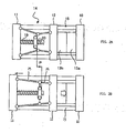
- Fig. 1 is an explanatory drawing of an embodiment of the mold clamping force adjustment device of the toggle type injection molding machine according to the present invention.
- the numeral 1 indicates a toggle type mold clamping system
- the numeral 2 indicates a controller for an injection molding machine comprising this toggle type mold clamping system.
- a fixed platen 10 and a rear platen 11 are coupled to each other by a plurality of tie bars 15, and a movable platen 12 is disposed movably between the fixed platen 10 and the rear platen 11 so as to be guided by the tie bars 15.
- a fixed mold half 13a is detachably attached to the fixed platen 10
- a movable mold half 13b is detachably attached to the movable platen 12.
- a toggle mechanism 14 is disposed between the rear platen 11 and the movable platen 12.
- the rear platen 11 is provided with a servomotor for mold clamping 18 for driving the toggle mechanism 14 and with a ball screw 19.
- the ball screw 19 is rotatably attached to the rear platen 11 such that the ball screw 19 cannot be moved in an axial direction, and the rear end (on the side opposite the movable platen 12 with respect to the rear platen 11) thereof comprises a driven pulley 22.
- An output shaft of the servomotor for mold clamping 18 provided in the rear platen 11 is provided with a drive pulley 21.
- a timing belt 23 is placed between the drive pulley 21 and the driven pulley 22, and the ball screw 19 is rotary driven by the servomotor for mold clamping 18.
- a tip end portion of the ball screw 19 is screwed with a nut fixed to the crosshead 20 of the toggle mechanism 14.
- the nut and the crosshead 20 fixing the nut are moved backward and forward (the horizontal direction in Fig. 1 ) to stretch and contract the toggle mechanism 14, and the movable platen 12 is moved backward and forward along the tie bars 15 (horizontal direction in the figure), thereby performing operations of mold closing, mold clamping, and mold opening.
- the numeral 24 is a position/speed detector for detecting a position and speed of the servomotor for mold clamping 18.
- a nut (not shown) screwing a screw (not shown) formed in the tie bar 15, and a rotating member 16 constituted by a gear are rotatably attached to the rear platen 11 such that they cannot be moved in the axial direction. Furthermore, a motor for mold thickness adjustment 17 is attached to the rear platen 11, and a gear provided in an output shaft of the motor for mold thickness adjustment 17 is coupled to a gear of the rotating members 16 respectively screwed to the tie bars 15 are coupled to each other by means of a gear transmission mechanism (not shown).
- adjustment of a mold clamping force is performed using the mold thickness adjusting mechanism that the injection molding machine comprises. Specifically, the adjustment is performed by driving the motor for mold thickness adjustment 17, rotating the rotating member 16, and moving the rear platen 11 forward or backward along the tie bar 15.
- the mold thickness adjusting mechanism is constituted by the rear platen 11, motor for mold thickness adjustment 17, rotating members 16, screw portion of the tie bar 15, and the like.
- the controller 2 comprises a processor 30 for controlling the injection molding machine, and a ROM 37 storing system programs, a RAM 38 performing primary storage of data and storing various control programs, a servo interface 33, an input-output circuit 35, and an interface 31 of a display/input means 32, which are connected to the processor 30 through a bus 39.
- the servomotor for mold clamping 18 which drives the toggle type mold clamping system 1 is connected to the servo interface 33 via a servo amplifier 34.
- various servomotors besides the servomotor 18 are used as the injection molding machine, and are also connected to the controller 2; however, the functions of these servomotors are not directly related to the present invention, and thus are omitted in Fig. 1 .
- an inverter 36 for driving the motor for mold thickness adjustment 17 is connected to the input-output circuit 35.
- the display/input means 32 which is connected to the interface 31 is constituted by a liquid crystal display, keyboard, and the like.
- the processor 30 of the controller 2 executes a program for a mold clamping operation and outputs a move command to the servo interface 33.
- the servo interface 33 performs position loop control processing and speed loop control processing on the basis of the move command, a position detected by the position/speed detector 24 attached to the servomotor for mold clamping 18, and a speed feedback signal, to perform control of drive of the servomotor for mold clamping 18.
- the crosshead 20 of the toggle mechanism 14 is moved by driving the servomotor for mold clamping 18, and, as a result, the movable platen 12 is moved, and the operations of mold closing, mold clamping and mold opening are carried out.
- the motor for mold thickness adjustment 17 is driven by means of the inverter 36 via the input-output circuit 35, and the mold thickness adjusting mechanism is activated to move the rear platen 11 forward or backward, whereby adjusting the mold clamping force is performed.
- adjustment of the mold clamping force is executed by means of the controller 2, the mold thickness adjusting mechanism (the rear platen 11, motor for mold thickness adjustment 17, rotating member 16, screw portion of the tie bar 15, and the like), and software (described hereinafter) for mold clamping force adjustment executed by the controller 2.
- the controller 2 of the injection molding machine serves also as the controller of the mold claming force adjustment device.
- Fig. 2A and Fig. 2B are figures for explaining generation of a mold clamping force caused by the toggle type mold clamping system 1.
- Fig. 2A shows a state in which the movable mold half 13b and the fixed mold half 13a touch each other in a state in which the toggle mechanism 14 of the toggle type mold clamping system 1 is contracted.
- the state shown in Fig. 2A When changing from the state shown in Fig. 2A to a lock-up state in which the toggle mechanism 14 is stretched by rotating the servomotor for mold clamping 18 to rotate the ball screw 19, and moving the crosshead 20 forward as far as a distance P (i.e. by arranging a first link 25 and a second link 26 in a single straight line), the state shown in Fig. 2B is reached.
- the tie bar 15 provided between the fixed platen 10 and the rear platen 11 is completely stretched, whereby the mold halves 13a and 13b are clamped by the counterforce thereof, and a mold clamping force corresponding to the distance P is generated.
- a mold clamping force is not generated, thus the tie bar 15 is not stretched. Furthermore, if the toggle mechanism 14 is bent to the extent which allows generation of a mold clamping force set by the toggle mechanism 14 of Fig. 2A (i.e. as long as the position of the crosshead 20 or the position of the movable platen 12 with respect to the rear platen 11 is placed in-positions necessary to generate the set mold clamping force), a mold clamping force as is set can be generated when the toggle mechanism is brought to the state shown in Fig. 2B (lock-up state) from the state shown in Fig. 2A (mold touch state).
- the present invention therefore is contrived such that the amount of stretch (generated mold clamping force) of the tie bar 15 in the mold touch position is obtained in advance as a correction amount, and an accurate set mold clamping force is obtained by using this correction amount when carrying out mold clamping force adjustment.
- Fig. 3A to Fig. 3D are figures for explaining a mold clamping force adjustment operation in an embodiment of the mold clamping force adjustment device according to the present invention.
- the mold halves 13a and 13b are attached to the fixed platen 10 and the movable platen 12 respectively.
- the servomotor for mold clamping 18 is driven, the ball screw 19 is rotated, and the toggle mechanism 14 is contracted, whereby the movable platen 12 is positioned in the position which is necessary to generate the set mold clamping force.
- determining a position of the movable platen 12 is the same as determining positions of the servomotor for mold clamping 18, crosshead 20, and movable mold half 13b.
- the distance between the rear platen 11 and the movable platen 12 at this time is "W".
- the motor for mold thickness adjustment 17 is driven, the rear platen 11 is moved forward, and the movable mold half 13b is brought into contact with the fixed mold half 13a.
- driving the motor for mold thickness adjustment 17 is stopped.
- This mold touch is detected by a generation of an overload signal (excess current signal) from the inverter 36 which drives the motor for mold thickness adjustment 17.
- An overload signal excess current signal
- the movable mold half 13b is separated from the fixed mold half 13a by driving the servomotor for mold clamping 18, rotating the ball screw 19, contracting the toggle mechanism 14, and making the distance between the rear platen 11 and the movable platen 12 shorter than the distance W corresponding to the set mold clamping force.
- the tie bar 15 extending as much as ⁇ L in Fig. 2B is contracted as far as ⁇ L.
- the rear platen 11 joined with the tie bar 15 by screws is moved forward as far as ⁇ L.
- the motor for mold thickness adjustment 17 is driven to move the rear platen 11 backward as far as the amount of stretch ⁇ L of the tie bar 15 at the time of the mold touch. Accordingly, positioning the rear platen 11 is completed, thereby completing the mold clamping force adjustment operation.
- the rear platen 11 is moved forward while keeping the distance W (corresponds to the set mold clamping force) between the rear platen 11 and the movable platen 12 to conduct mold touch ( Fig. 3B ). Then, the rear platen 11 is moved backward, from its current position, as far as the amount of stretch ⁇ L of the tie bar 15 obtained in the previous mold touch.
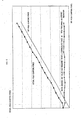
- Fig. 5 is a graph showing a relationship between the amount of a movement of a crosshead 20 (corresponds to the amount of movement of the servomotor for mold clamping) from the time of mold touch ( Fig. 2A ) to the lock-up time ( Fig. 2B ) of the toggle mechanism 14 and a generated mold clamping force. If a mold clamping force to be generated with respect to the selected mold halves 13a and 13b is set, the amount of movement of the crosshead 20 which is necessary to provide the set mold clamping force can be obtained from this graph.
- the amount of movement of the crosshead 20 is stored in a form of the amount of movement of the servomotor for mold clamping in a predetermined region in the RAM 38 of the controller 2. Further, a worker may set and input the amount of movement of the crosshead in accordance with the set mold clamping force by using the graph of this relationship.
- an overload signal (excess current signal) is generated from the inverter 36.
- the stretch of the tie bar 15 at the time when this overload signal is detected i.e. the amount of stretch ⁇ L shown in Fig. 3B , is obtained in an experiment in advance.
- a drive time ⁇ T of the motor for mold thickness adjustment 17 necessary to move the rear platen 11 backward as much as the amount of stretch ⁇ L is obtained in an experiment in advance and stored in the controller 2.
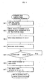
- Fig. 4 is a flow chart showing a mold clamping adjustment work.
- Step S1 When a mold clamping force adjustment command is input, the processor 30 of the controller 2 activates the motor for mold thickness adjustment 17 through the input-output circuit 35 ( Fig. 1 ) to move the rear platen 11 backward to a set backward end (Step S1).
- an amount of movement CP of the crosshead 20, which is necessary to provide a set mold clamping force is obtained by means of the data of the relationship ( Fig. 5 ) between the amount of movement of the crosshead 20 of the toggle mechanism and the generated mold clamping force (Step S2).
- the servomotor for mold clamping 18 is driven and the crosshead 20 is moved to CP (Step S3). Due to this movement of the crosshead 20, the movable platen 12 is moved toward the rear platen 11, whereby the distance between the movable platen 12 and the rear platen 11 becomes the distance W corresponding to the set mold clamping force ( Fig. 3A ).
- Step S4 the motor for mold thickness adjustment 17 is driven and the rear platen 11 is moved forward (Step S4). Then, it is monitored whether or not an overload signal (excess current signal) is generated from the inverter 36 which drives the motor 17 (Step S5). If an overload signal (excess current signal) is detected, the drive of the motor for mold thickness adjustment 17 is stopped to stop the forward movement of the rear platen 11 (Step S6). In this state the tie bar 15 is stretched as much as ⁇ L, as shown in Fig. 3B .
- Step S7 the motor for mold thickness adjustment 17 is driven for a period of time ⁇ T, which is set, and the rear platen 11 is moved backward as much as the distance ⁇ L (Step S7). Accordingly, the distance between the rear platen 11 and the movable platen 12 becomes the distance W corresponding to the set mold clamping force when mold touch occurs (also when less mold clamping force is generated). Consequently, the mold clamping force adjustment work is finished.
- Fig. 6 and Fig. 7 show results of experiment for confirming the effects of the present invention with respect to the conventional technologies.
- Fig. 6 Inventional technology, an arbitrary mold clamping force is set, and the motor for mold thickness adjustment 17 is operated to move the rear platen 11 forward in a state in which the toggle mechanism 14 is contracted as much as the amount corresponding to the set mold clamping force, and mold touch is detected.
- the rear platen 11 is stopped, and thereafter the toggle mechanism is driven to move the movable platen 12 forward to a lock-up position. Then, when the toggle mechanism is in the lock-up position the mold clamping force is actually measured.
- An "actual mold clamping force" in Fig. 6 means a mold clamping force obtained by actually measuring the mold clamping force.
- Fig. 7 is an experimental result when performing a correction according to the present invention. Specifically, an arbitrary mold clamping force is set, and the motor for mold thickness adjustment 17 is operated to move the rear platen 11 forward in a state in which the toggle mechanism is contracted corresponding amount with respect to the set mold clamping force, and mold touch is detected. When mold touch is detected, the forward movement of the rear platen 11 is stopped. Thereafter, the rear platen 11 is moved a preset correction amount ⁇ L backward from the stop position. Consequently, positioning of the rear platen 11 is finished. Next, the toggle mechanism 14 is driven to move the movable platen 12 forward to reach a lock-up position, and a mold clamping force at this time is detected. Through this series of works, it is found that the actual mold clamping force is substantially equated with the set mold clamping force.
- the fact that the mold halves touched each other is detected by means of an overload signal (excess current signal) outputted from the inverter.
- the mold touch may be detected by means of a current excess signal generated from a thermal relay incorporated in a geared motor drive circuit.
- mold touch may be detected by a pressure increase signal which indicates that the pressure from a hydraulic system has reached a predetermined level.
- the suppress strength of the mold halves when a mold touch detection signal is outputted is constant regardless of the thicknesses of the mold halves, thus the stretch of the tie bar 15 corresponding to this constant suppress strength is a constant amount of ⁇ L, which may be taken as the correction amount.
- the amount of backward movement of the rear platen 11 is determined by a time in Step S7 of Fig. 4 .
- the amount of backward movement ⁇ L of the rear platen 11 may be determined not by a time but by the amount of movement detected by the position sensor.
- the toggle mechanism 14 is contracted as necessary to provide a set mold clamping force (i.e. the toggle mechanism 14 is positioned to a place where the crosshead 20 is moved as much as CP (see Step S2 in Fig. 4 ) backward from the lock-up position), and the rear platen 11 is moved forward to cause mold touch.
- the toggle mechanism 14 does not necessarily have to be contracted as much as to be equivalent to the set mold clamping force.
- the rear platen 11 is moved forward to cause mold touch while stretching the toggle mechanism 14 to the lock-up state, and the rear platen 11 may be moved backward as much as the amount of stretch ⁇ L (constant regardless of the state of the toggle mechanism 14) of the tie bar 15 at the time of the mold touch. Accordingly, the state of mold touch can be obtained in a state in which little stretch of the tie bar 15 is observed.
- the toggle mechanism 14 is contracted, the rear platen 11 is moved forward by the distance corresponding to the set mold clamping force.
- the toggle mechanism 14 is brought from its contracted state to the lock-up state, whereby a mold clamping force as is set can be obtained.
- the toggle type mold clamping system comprises the position sensor for detecting the amount of movement of the rear platen 11 and obtains the distance between the rear platen 11 and the movable platen 12 by means of calculation using the position sensor or the position/speed detector 24, the stretch of the toggle mechanism 14 at the time of mold touch may be in any extent.
- a distance W1 between the rear platen 11 and the movable platen 12 at the time when the mold touch each other in an arbitrary contraction state of the toggle mechanism 14 is obtained by the position sensor or the position/speed detector 24.
- the relationship data is used to obtain a distance W0 between the rear platen 11 and the movable platen 12 in a state in which the toggle mechanism is contracted as much as to be equivalent to the set mold clamping force.
- the rear platen 11 is moved the amount of movement of W0 and W1, whereby the set mold clamping force can be obtained.
Landscapes
- Engineering & Computer Science (AREA)
- Manufacturing & Machinery (AREA)
- Mechanical Engineering (AREA)
- Moulds For Moulding Plastics Or The Like (AREA)
- Injection Moulding Of Plastics Or The Like (AREA)
Claims (4)
- Verfahren zum Einstellen der Formspannkraft bei einer Knebel-Spritzgussmaschine, wobei das Verfahren dadurch gekennzeichnet ist, dass es die Schritte umfasst:Vorwärtsbewegen einer hinteren Platte (11) der Formmaschine in einen Zustand, in dem ein Knebelmechanismus (14) eines Knebel-Formspannsystems (1) der Formmaschine um einen Betrag (Cp) verkürzt wird, der einer vorher eingestellten Formspannkraft entspricht;
Erfassen, wann eine bewegliche Formhälfte (13b) eine feste Formhälfte (13a) der Formmaschine berührt; undwenn es erfasst wird, dass die bewegliche Formhälfte (13b) die feste Formhälfte (13a) berührt,
Zurückbewegen der hinteren Platte (11) um einen Betrag (ΔL), der einer Presskraft entspricht, die erzeugt wird, wenn die bewegliche Hälfte (13b) die feste Formhälfte (13a) berührt. - Verfahren zum Einstellen der Formspannkraft bei einer Knebel-Spritzgussmaschine, wobei das Verfahren die Schritte umfasst:Vorwärtsbewegen einer hinteren Platte (11) der Formmaschine in einen Zustand, in dem ein Knebelmechanismus (14) eines Knebel-Formspannsystems (1) der Gussmaschine gestreckt ist;Erfassen, wann eine bewegliche Formhälfte (13b) eine feste Formhälfte (13a) der Gussmaschine berührt;wobei das Verfahren gekennzeichnet ist durch:wenn erfasst wird, dass die bewegliche Formhälfte (13b) die feste Formhälfte (13a) berührt,
Zurückbewegen der hinteren Platte (11) um einen Betrag (ΔL), der einer Presskraft entspricht, die erzeugt wird, wenn die bewegliche Hälfte (13b) die feste Formhälfte (13a) berührt, und Verkürzen des Knebelmechanismus (14), so dass ein beliebiger Zustand erreicht wird; und
Vorwärtsbewegen der hinteren Platte (11) um einen Betrag (Cp), der einer eingestellten Formspannkraft entspricht. - Verfahren zum Einstellen der Formspannkraft nach Anspruch 1 oder 2, wobei der Betrag der Rückwärtsbewegung der hinteren Platte (11) durch Erfassen der Position der hinteren Platte gesteuert wird.
- Verfahren zum Einstellen der Formspannkraft nach Anspruch 1 oder 2, wobei der Betrag der Rückwärtsbewegung der hinteren Platte (11) eingestellt wird, mit einem Zeitraum (ΔT) zum Zurückbewegen der hinteren Platte.
Applications Claiming Priority (2)
| Application Number | Priority Date | Filing Date | Title |
|---|---|---|---|
| JP2004095907 | 2004-03-29 | ||
| JP2004095907A JP3962725B2 (ja) | 2004-03-29 | 2004-03-29 | トグル式射出成形機の型締力調整装置 |
Publications (2)
| Publication Number | Publication Date |
|---|---|
| EP1584445A1 EP1584445A1 (de) | 2005-10-12 |
| EP1584445B1 true EP1584445B1 (de) | 2008-08-13 |
Family
ID=34909431
Family Applications (1)
| Application Number | Title | Priority Date | Filing Date |
|---|---|---|---|
| EP05251779A Ceased EP1584445B1 (de) | 2004-03-29 | 2005-03-23 | Einstellverfahren zum Regeln der Formschliesskraft eines Kniehebelformschließsystems für eine Spritzgiessmaschine |
Country Status (5)
| Country | Link |
|---|---|
| US (1) | US7210918B2 (de) |
| EP (1) | EP1584445B1 (de) |
| JP (1) | JP3962725B2 (de) |
| CN (1) | CN1676303A (de) |
| DE (1) | DE602005008798D1 (de) |
Families Citing this family (27)
| Publication number | Priority date | Publication date | Assignee | Title |
|---|---|---|---|---|
| JP4477546B2 (ja) * | 2005-06-02 | 2010-06-09 | 住友重機械工業株式会社 | 成形条件設定方法 |
| JP4836742B2 (ja) * | 2006-10-10 | 2011-12-14 | 株式会社ダイセン工業 | 発泡成形機及びその運転方法 |
| JP4836611B2 (ja) * | 2006-03-02 | 2011-12-14 | 株式会社ダイセン工業 | 発泡樹脂成形機の運転方法 |
| EP1997601A4 (de) * | 2006-03-02 | 2013-10-09 | Daisen Industry Co Ltd | Formwerkzeug für aufschäumbares harz und betriebsverfahren dafür |
| US20090005157A1 (en) * | 2007-06-28 | 2009-01-01 | Netley Neil J | Electronic funds transfer system and method of use in gaming environment |
| DE102007043673B4 (de) * | 2007-09-13 | 2009-10-15 | Adcuram Maschinenbauholding Gmbh | Verfahren zum sicheren Schließen eines Werkzeugs |
| JP5377905B2 (ja) * | 2008-08-11 | 2013-12-25 | ポリプラスチックス株式会社 | 金型、成形品評価方法、及び成形条件決定方法 |
| JP4787894B2 (ja) * | 2009-07-23 | 2011-10-05 | 日精樹脂工業株式会社 | トグル式型締装置の型厚調整方法 |
| JP2011183705A (ja) * | 2010-03-09 | 2011-09-22 | Sumitomo Heavy Ind Ltd | 射出成形機及び射出成形方法 |
| TW201228799A (en) * | 2011-01-07 | 2012-07-16 | Acumen Co Ltd | Electrical injection molding machine |
| JP2013126722A (ja) * | 2011-12-16 | 2013-06-27 | Sumitomo Heavy Ind Ltd | 射出成形機 |
| CN102922710B (zh) * | 2012-11-08 | 2015-03-25 | 广西柳州中嘉知识产权服务有限公司 | 塑料注塑机 |
| JP5596105B2 (ja) | 2012-11-09 | 2014-09-24 | ファナック株式会社 | 射出成形機の型厚調整装置 |
| JP5800289B2 (ja) * | 2013-02-26 | 2015-10-28 | 村田機械株式会社 | 型締装置の管理システム |
| BE1021675B1 (de) * | 2013-04-26 | 2016-01-05 | Gb Boucherie Nv | Spritzgiessvorrichtung |
| JP5734366B2 (ja) | 2013-07-26 | 2015-06-17 | ファナック株式会社 | 射出成形機の型締力測定機構 |
| CN104802380B (zh) * | 2014-01-24 | 2018-10-26 | 东芝机械株式会社 | 成形机及其驱动方法 |
| JP6505403B2 (ja) * | 2014-03-13 | 2019-04-24 | 住友重機械工業株式会社 | 射出成形機、射出成形機の情報処理装置、および射出成形機の情報処理方法 |
| WO2015140925A1 (ja) * | 2014-03-18 | 2015-09-24 | Ykk株式会社 | 射出成形機 |
| KR101972477B1 (ko) * | 2014-12-24 | 2019-04-25 | 엘에스엠트론 주식회사 | 사출 성형기 및 형두께 제어 방법 |
| CN108698292B (zh) * | 2016-03-25 | 2021-04-09 | 住友重机械工业株式会社 | 注射成型机 |
| JP6751037B2 (ja) * | 2017-02-28 | 2020-09-02 | 住友重機械工業株式会社 | 射出成形機 |
| CN107263835A (zh) * | 2017-07-13 | 2017-10-20 | 江苏联宇医疗器械有限公司 | 一种医药用的注塑机 |
| JP7132080B2 (ja) * | 2018-10-17 | 2022-09-06 | 住友重機械工業株式会社 | 射出成形機 |
| JP7152243B2 (ja) * | 2018-10-17 | 2022-10-12 | 住友重機械工業株式会社 | 射出成形機 |
| JP6876086B2 (ja) * | 2019-04-01 | 2021-05-26 | 日精樹脂工業株式会社 | 動作設定装置を備えた射出成形機 |
| CN110497593B (zh) * | 2019-09-17 | 2021-12-07 | 宁波市北仑复力机械有限公司 | 一种注塑机的运行方法 |
Family Cites Families (16)
| Publication number | Priority date | Publication date | Assignee | Title |
|---|---|---|---|---|
| DE1558277A1 (de) * | 1967-07-26 | 1970-03-19 | Mahle Werk Gmbh | Einrichtung zum Regeln des Schliessdruckes von durch Knjehebel betaetigten Formhaltepressen fuer Druckgiessmaschinen |
| US3819774A (en) * | 1968-05-09 | 1974-06-25 | Buehler Ag Geb | Method for controlling operation of a press |
| DE2020053A1 (de) * | 1970-04-24 | 1971-11-04 | Krauss Maffei Ag | Spritzgiessmaschine mit automatischer Einstellung der Formeinbauhoehe |
| US3840313A (en) * | 1972-11-01 | 1974-10-08 | Litton Industrial Products | Molding machine clamp force indicator |
| US4301100A (en) * | 1979-10-01 | 1981-11-17 | Package Machinery Company | Method and apparatus for setting a clamping load |
| JPS62220314A (ja) | 1986-03-22 | 1987-09-28 | Fanuc Ltd | 射出成形機における型厚調整方法 |
| US4685876A (en) * | 1986-03-24 | 1987-08-11 | Cincinnati Milacron Inc. | Toggle injection molding clamping force monitor |
| JPH0825213B2 (ja) * | 1992-02-10 | 1996-03-13 | 株式会社新潟鉄工所 | 電動式射出成形機における型締力調整方法 |
| WO1993025368A1 (de) * | 1992-06-09 | 1993-12-23 | Klöckner Ferromatik Desma Gmbh | Verfahren zur werkzeughöheneinstellung von kniehebel-schliessystemen, insbesondere an spritzgiessmaschinen |
| JP2783124B2 (ja) | 1993-06-28 | 1998-08-06 | 三菱電機株式会社 | 熱延鋼材の温度制御方法 |
| JP2798171B2 (ja) * | 1993-09-28 | 1998-09-17 | 宇部興産株式会社 | 型締装置の型締力検出方法 |
| US5945047A (en) * | 1997-03-13 | 1999-08-31 | The Japan Steel Works, Ltd. | Method of injection-compression molding |
| JP3729975B2 (ja) | 1997-04-04 | 2005-12-21 | 株式会社日本製鋼所 | トグル式射出成形機の型締力設定方法 |
| JP3581061B2 (ja) * | 1999-10-29 | 2004-10-27 | 東芝機械株式会社 | 射出成形機の型厚調整方法および装置 |
| US6595766B2 (en) * | 2000-01-28 | 2003-07-22 | Toshiba Kikai Kabushiki Kaisha | Die clamping apparatus, die clamping force measurement method and die clamping force adjustment method |
| JP3822774B2 (ja) * | 2000-03-02 | 2006-09-20 | 株式会社日本製鋼所 | トグル式射出成形機の型締力調整方法 |
-
2004
- 2004-03-29 JP JP2004095907A patent/JP3962725B2/ja not_active Expired - Fee Related
-
2005
- 2005-03-23 EP EP05251779A patent/EP1584445B1/de not_active Ceased
- 2005-03-23 DE DE602005008798T patent/DE602005008798D1/de not_active Expired - Fee Related
- 2005-03-28 CN CN200510058808.6A patent/CN1676303A/zh active Pending
- 2005-03-29 US US11/092,588 patent/US7210918B2/en not_active Expired - Fee Related
Also Published As
| Publication number | Publication date |
|---|---|
| US7210918B2 (en) | 2007-05-01 |
| DE602005008798D1 (de) | 2008-09-25 |
| JP2005280047A (ja) | 2005-10-13 |
| EP1584445A1 (de) | 2005-10-12 |
| JP3962725B2 (ja) | 2007-08-22 |
| US20050214407A1 (en) | 2005-09-29 |
| CN1676303A (zh) | 2005-10-05 |
Similar Documents
| Publication | Publication Date | Title |
|---|---|---|
| EP1584445B1 (de) | Einstellverfahren zum Regeln der Formschliesskraft eines Kniehebelformschließsystems für eine Spritzgiessmaschine | |
| EP1645395B1 (de) | Steuerung einer Spritzgiessmaschine | |
| JP3694684B2 (ja) | 射出成形機 | |
| CN101111359B (zh) | 成形条件设定方法以及射出成形机的控制方法 | |
| US7892463B2 (en) | Mold clamping force correction method for mold clamping apparatus | |
| JP4272205B2 (ja) | 射出成形機の制御方法 | |
| JP4477546B2 (ja) | 成形条件設定方法 | |
| JP4568350B2 (ja) | 射出成形機の異常検出装置 | |
| JP4410749B2 (ja) | トグル式型締装置の型厚調整方法 | |
| JPH07106580B2 (ja) | ノズルタッチ装置 | |
| US7287971B2 (en) | Load determining device for an electrically-operated injection molding machine | |
| JP2010162558A (ja) | 曲げ加工機 | |
| JP4689559B2 (ja) | 型締装置及び型締装置の制御方法 | |
| JPH0661806B2 (ja) | トグル式型締装置の自動型締力設定方法 | |
| JP4231474B2 (ja) | トグル式型締装置の型締方法 | |
| JP4727477B2 (ja) | 型締力制御方法 | |
| JP2814262B2 (ja) | 自動型厚調整方法 | |
| JP4724050B2 (ja) | 射出成形機の型締制御方法 | |
| JP6077427B2 (ja) | 射出成形機の制御装置及び制御方法 | |
| JP2006015552A (ja) | トグル式型締装置の型厚調整方法 | |
| JP2709868B2 (ja) | ダイハイト調整方法 | |
| JP2678700B2 (ja) | 射出成形機の型厚測定方法 | |
| JP2001277248A (ja) | 型締装置、型締力測定方法および型締力調整方法 | |
| JPH06297531A (ja) | 射出成形機の制御装置 | |
| JPS63116821A (ja) | 型締装置の金型接触位置設定方法及び装置 |
Legal Events
| Date | Code | Title | Description |
|---|---|---|---|
| PUAI | Public reference made under article 153(3) epc to a published international application that has entered the european phase |
Free format text: ORIGINAL CODE: 0009012 |
|
| AK | Designated contracting states |
Kind code of ref document: A1 Designated state(s): AT BE BG CH CY CZ DE DK EE ES FI FR GB GR HU IE IS IT LI LT LU MC NL PL PT RO SE SI SK TR |
|
| AX | Request for extension of the european patent |
Extension state: AL BA HR LV MK YU |
|
| 17P | Request for examination filed |
Effective date: 20060320 |
|
| AKX | Designation fees paid |
Designated state(s): DE |
|
| RTI1 | Title (correction) |
Free format text: MOLD CLAMPING FORCE ADJUSTMENT METHOD OF TOGGLE TYPE INJECTION MOLDING MACHINE |
|
| GRAP | Despatch of communication of intention to grant a patent |
Free format text: ORIGINAL CODE: EPIDOSNIGR1 |
|
| GRAS | Grant fee paid |
Free format text: ORIGINAL CODE: EPIDOSNIGR3 |
|
| GRAA | (expected) grant |
Free format text: ORIGINAL CODE: 0009210 |
|
| AK | Designated contracting states |
Kind code of ref document: B1 Designated state(s): DE |
|
| REF | Corresponds to: |
Ref document number: 602005008798 Country of ref document: DE Date of ref document: 20080925 Kind code of ref document: P |
|
| PLBE | No opposition filed within time limit |
Free format text: ORIGINAL CODE: 0009261 |
|
| STAA | Information on the status of an ep patent application or granted ep patent |
Free format text: STATUS: NO OPPOSITION FILED WITHIN TIME LIMIT |
|
| 26N | No opposition filed |
Effective date: 20090514 |
|
| PGFP | Annual fee paid to national office [announced via postgrant information from national office to epo] |
Ref country code: DE Payment date: 20090319 Year of fee payment: 5 |
|
| PG25 | Lapsed in a contracting state [announced via postgrant information from national office to epo] |
Ref country code: DE Free format text: LAPSE BECAUSE OF NON-PAYMENT OF DUE FEES Effective date: 20101001 |