EP1584445B1 - Mold clamping force adjustment method of toggle type injection molding machine - Google Patents
Mold clamping force adjustment method of toggle type injection molding machine Download PDFInfo
- Publication number
- EP1584445B1 EP1584445B1 EP05251779A EP05251779A EP1584445B1 EP 1584445 B1 EP1584445 B1 EP 1584445B1 EP 05251779 A EP05251779 A EP 05251779A EP 05251779 A EP05251779 A EP 05251779A EP 1584445 B1 EP1584445 B1 EP 1584445B1
- Authority
- EP
- European Patent Office
- Prior art keywords
- mold
- mold clamping
- clamping force
- rear platen
- platen
- Prior art date
- Legal status (The legal status is an assumption and is not a legal conclusion. Google has not performed a legal analysis and makes no representation as to the accuracy of the status listed.)
- Expired - Fee Related
Links
Images


Classifications
-
- B—PERFORMING OPERATIONS; TRANSPORTING
- B29—WORKING OF PLASTICS; WORKING OF SUBSTANCES IN A PLASTIC STATE IN GENERAL
- B29C—SHAPING OR JOINING OF PLASTICS; SHAPING OF MATERIAL IN A PLASTIC STATE, NOT OTHERWISE PROVIDED FOR; AFTER-TREATMENT OF THE SHAPED PRODUCTS, e.g. REPAIRING
- B29C45/00—Injection moulding, i.e. forcing the required volume of moulding material through a nozzle into a closed mould; Apparatus therefor
- B29C45/17—Component parts, details or accessories; Auxiliary operations
- B29C45/76—Measuring, controlling or regulating
- B29C45/7653—Measuring, controlling or regulating mould clamping forces
-
- B—PERFORMING OPERATIONS; TRANSPORTING
- B29—WORKING OF PLASTICS; WORKING OF SUBSTANCES IN A PLASTIC STATE IN GENERAL
- B29C—SHAPING OR JOINING OF PLASTICS; SHAPING OF MATERIAL IN A PLASTIC STATE, NOT OTHERWISE PROVIDED FOR; AFTER-TREATMENT OF THE SHAPED PRODUCTS, e.g. REPAIRING
- B29C45/00—Injection moulding, i.e. forcing the required volume of moulding material through a nozzle into a closed mould; Apparatus therefor
- B29C45/17—Component parts, details or accessories; Auxiliary operations
- B29C45/1751—Adjustment means allowing the use of moulds of different thicknesses
-
- B—PERFORMING OPERATIONS; TRANSPORTING
- B29—WORKING OF PLASTICS; WORKING OF SUBSTANCES IN A PLASTIC STATE IN GENERAL
- B29C—SHAPING OR JOINING OF PLASTICS; SHAPING OF MATERIAL IN A PLASTIC STATE, NOT OTHERWISE PROVIDED FOR; AFTER-TREATMENT OF THE SHAPED PRODUCTS, e.g. REPAIRING
- B29C2945/00—Indexing scheme relating to injection moulding, i.e. forcing the required volume of moulding material through a nozzle into a closed mould
- B29C2945/76—Measuring, controlling or regulating
- B29C2945/76003—Measured parameter
- B29C2945/76083—Position
-
- B—PERFORMING OPERATIONS; TRANSPORTING
- B29—WORKING OF PLASTICS; WORKING OF SUBSTANCES IN A PLASTIC STATE IN GENERAL
- B29C—SHAPING OR JOINING OF PLASTICS; SHAPING OF MATERIAL IN A PLASTIC STATE, NOT OTHERWISE PROVIDED FOR; AFTER-TREATMENT OF THE SHAPED PRODUCTS, e.g. REPAIRING
- B29C2945/00—Indexing scheme relating to injection moulding, i.e. forcing the required volume of moulding material through a nozzle into a closed mould
- B29C2945/76—Measuring, controlling or regulating
- B29C2945/76003—Measured parameter
- B29C2945/7611—Velocity
-
- B—PERFORMING OPERATIONS; TRANSPORTING
- B29—WORKING OF PLASTICS; WORKING OF SUBSTANCES IN A PLASTIC STATE IN GENERAL
- B29C—SHAPING OR JOINING OF PLASTICS; SHAPING OF MATERIAL IN A PLASTIC STATE, NOT OTHERWISE PROVIDED FOR; AFTER-TREATMENT OF THE SHAPED PRODUCTS, e.g. REPAIRING
- B29C2945/00—Indexing scheme relating to injection moulding, i.e. forcing the required volume of moulding material through a nozzle into a closed mould
- B29C2945/76—Measuring, controlling or regulating
- B29C2945/76177—Location of measurement
- B29C2945/76224—Closure or clamping unit
- B29C2945/7623—Closure or clamping unit clamping or closing drive means
-
- B—PERFORMING OPERATIONS; TRANSPORTING
- B29—WORKING OF PLASTICS; WORKING OF SUBSTANCES IN A PLASTIC STATE IN GENERAL
- B29C—SHAPING OR JOINING OF PLASTICS; SHAPING OF MATERIAL IN A PLASTIC STATE, NOT OTHERWISE PROVIDED FOR; AFTER-TREATMENT OF THE SHAPED PRODUCTS, e.g. REPAIRING
- B29C2945/00—Indexing scheme relating to injection moulding, i.e. forcing the required volume of moulding material through a nozzle into a closed mould
- B29C2945/76—Measuring, controlling or regulating
- B29C2945/76344—Phase or stage of measurement
- B29C2945/76391—Mould clamping, compression of the cavity
-
- B—PERFORMING OPERATIONS; TRANSPORTING
- B29—WORKING OF PLASTICS; WORKING OF SUBSTANCES IN A PLASTIC STATE IN GENERAL
- B29C—SHAPING OR JOINING OF PLASTICS; SHAPING OF MATERIAL IN A PLASTIC STATE, NOT OTHERWISE PROVIDED FOR; AFTER-TREATMENT OF THE SHAPED PRODUCTS, e.g. REPAIRING
- B29C2945/00—Indexing scheme relating to injection moulding, i.e. forcing the required volume of moulding material through a nozzle into a closed mould
- B29C2945/76—Measuring, controlling or regulating
- B29C2945/76494—Controlled parameter
- B29C2945/76505—Force
-
- B—PERFORMING OPERATIONS; TRANSPORTING
- B29—WORKING OF PLASTICS; WORKING OF SUBSTANCES IN A PLASTIC STATE IN GENERAL
- B29C—SHAPING OR JOINING OF PLASTICS; SHAPING OF MATERIAL IN A PLASTIC STATE, NOT OTHERWISE PROVIDED FOR; AFTER-TREATMENT OF THE SHAPED PRODUCTS, e.g. REPAIRING
- B29C2945/00—Indexing scheme relating to injection moulding, i.e. forcing the required volume of moulding material through a nozzle into a closed mould
- B29C2945/76—Measuring, controlling or regulating
- B29C2945/76494—Controlled parameter
- B29C2945/76568—Position
-
- B—PERFORMING OPERATIONS; TRANSPORTING
- B29—WORKING OF PLASTICS; WORKING OF SUBSTANCES IN A PLASTIC STATE IN GENERAL
- B29C—SHAPING OR JOINING OF PLASTICS; SHAPING OF MATERIAL IN A PLASTIC STATE, NOT OTHERWISE PROVIDED FOR; AFTER-TREATMENT OF THE SHAPED PRODUCTS, e.g. REPAIRING
- B29C2945/00—Indexing scheme relating to injection moulding, i.e. forcing the required volume of moulding material through a nozzle into a closed mould
- B29C2945/76—Measuring, controlling or regulating
- B29C2945/76822—Phase or stage of control
- B29C2945/76869—Mould clamping, compression of the cavity
Description
- The present invention relates to a mold clamping force adjustment device of an injection molding machine having a toggle type mold clamping system.
- In an injection molding machine having a toggle type mold clamping system, a toggle mechanism of the toggle type mold clamping system is built between a movable platen and a rear platen. When closing the mold, first of all a movable mold half and a fixed mold half are caused to touch each other in a contraction state of the toggle mechanism. Then, the toggle mechanism is stretched and a tie bar which couples a fixed platen to the rear platen is stretched. Under such condition in which the toggle mechanism is stretched completely ("lock-up state"), a set mold clamping force is generated between the movable mold half and the front mold half by the reaction force (elastic force) of the stretched tie bar.
- As above, a mold clamping force is determined based on the amount of stretch of the toggle mechanism from the time when the toggle mechanism is contracted to cause the mold halves to touch each other until the time when the toggle mechanism is stretched completely and applies the set mold clamping force to the mold halves (i.e. the amount of movement of the movable platen). Therefore, it is necessary to adjust the position of the rear platen (mold clamping force adjustment) so that the toggle mechanism is contracted as much as the amount corresponding to a desired amount of stretch to cause the mold halves to touch each other.
- Examples of the conventional technologies of such mold clamping force adjustment will now be described hereinafter.
- (1) Mold clamping force adjustment described in
Japanese Patent Application Laid-Open Publication No. JP 62-220314
A toggle mechanism of a toggle type mold clamping system is contracted as much as the amount necessary to generate a mold clamping force that is set. A torque limit is applied to a servomotor which drives the toggle type mold clamping system, and a geared motor which drives a rear platen is rotated normally. Since an output torque of the servomotor is limited, when the mold halves touch, the toggle mechanism is contracted, and the servomotor is rotated, whereby the value of the error resistor (error value) is increased. When the error value reaches a set value, the drive of the geared motor is stopped. Thereafter, the geared motor is rotated backward, the rear platen and the movable platen (movable mold half) are moved backward, and the mold is opened. Then the movable platen is moved forward as much as the amount of the error value. Furthermore, the torque limit of the servomotor is canceled, the geared motor is rotated normally for a predetermined period of time, and the rear platen and the movable platen (movable mold half) are moved forward. By determining the position of the rear platen as above, the mold clamping force is adjusted. - (2) Mold clamping force adjustment described in
Japanese Utility Model Examined Publication No. H7-32024
There is provided a thermal relay for detecting excess current of a motor for mold thickness adjustment which drives a toggle support of a toggle type mold clamping system. The toggle mechanism of the toggle type mold clamping system is caused to move forward in a state where a set mold clamping force is contracted by the necessary amount to generate. When mold touch occurs, the thermal relay detecting the excess current of the motor for mold thickness adjustment is turned off. This is detected to stop the drive of the motor for mold thickness adjustment and to finish mold thickness adjustment. - (3) Mold clamping force adjustment described in
Japanese Patent Application Laid-Open Publication No. JP10-278084 Japanese Patent Application Laid-Open Publication No. JP2001-239562
The amount of stretch of a tie bar at the time when a toggle mechanism of the toggle type mold clamping system is driven to cause mold touch by means of certain pressing pressure is determined in advance, the amount of stretch of the tie bar is corrected, and the position of the rear platen is determined. - As described above, the toggle type mold clamping system generates a set mold clamping force by using the movement of the movable platen from the time when the mold is touched until the time when the toggle mechanism is brought to the lock-up state. To that end, the position of the movable platen at the time when the mold is touched needs to be detected accurately. If the tie bar is stretched at the time when it is detected that the mold is touched, thereby generating a mold clamping force, the mold clamping force to be generated is increased more than the set mold clamping force by that much.
- In the case of the conventional technologies (1) and (2), a mold clamping force is already applied to the mold when mold touch is detected. Therefore, by using the toggle mechanism to move the movable plate as much as the amount necessary to generate a set mold clamping force, the amount of a mold clamping force which is actually generated is larger than the set mold clamping force.
- In the case of the conventional technology (3) above, on the other hand, the position of the rear platen is determined so that a set mold clamping force is obtained by correcting the stretch of the tie bar that occurs at the time of mold touch. However, the motor for driving the toggle mechanism is driven in order to cause mold touch so as to obtain the amount of correction, thus a pressing force (mold clamping force) to the mold that is generated varies depending on the bending state of the toggle mechanism. Consequently, this correction amount varies depending on the thickness of the mold, thus it is necessary to measure this correction amount for every mold clamping force adjustment performed in accordance with the mold thicknes, which requires time and effort in a mold clamping force adjustment work.
-
WO 9325368 -
DE 2020053 discloses an injection molding machine for molding thermoplastics, the machine intended to deliver a desired mold closing force by adjustment of the toggle mechanism and movement of the platens. - A first embodiment of a mold clamping force adjustment method of a toggle type injection molding machine according to the present invention, comprises steps of: moving a rear platen of the molding machine forward in a state in which a toggle mechanism of a toggle type mold clamping system of the molding machine is contracted as much as an amount corresponding to a mold clamping force which is set in advance; detecting when a movable mold half touches a fixed mold half of the molding machine; and when it is detected that the movable mold half touches the fixed mold half, moving the rear platen backward as much as an amount corresponding to a compressive force generated when the movable mold half touches the fixed mold half.
- A second embodiment of a mold clamping force adjustment method of a toggle type injection molding machine according to the present invention, comprises steps of moving a rear platen of the molding machine forward, in a state in which a toggle mechanism of a toggle type mold clamping system of the molding machine is stretched; detecting when a movable mold half touches a fixed mold half of the molding machine; when it is detected that the movable mold half touches the fixed mold half, moving the rear platen backward as much as an amount corresponding to a compressive force generated when the movable mold half touches the fixed mold half and contracting the toggle mechanism to reach an arbitrary state; and moving the rear platen forward by an amount corresponding to a set mold clamping force.
- The amount of a backward movement of the rear platen can be controlled by the position of the rear platen. The amount of the backward movement of the rear platen can be adjusted by a time for moving the rear platen backward.
- Since the mold clamping force adjustment methods of the toggle type injection molding machine comprise the above-described steps, the set mold clamping force can be generated more accurately and easily.
- The above-described and other objects and characteristics of the present invention may be clear from the explanations of the embodiments below with reference to the attached drawings. Among these figures:
-
Fig. 1 is an explanatory drawing of an embodiment of the mold clamping force adjustment device of the toggle type injection molding machine according to the present invention; -
Fig. 2A and Fig. 2B are figures for explaining generation of a mold clamping force caused by a toggle type mold clamping system; -
Fig. 3A to Fig. 3D are figures for explaining a mold clamping force adjustment operation in an embodiment of the mold clamping force adjustment device according to the present invention; -
Fig. 4 is a flow chart showing a mold clamping adjustment work; -
Fig. 5 is a graph showing a relationship between the amount of a movement of a crosshead from the time of mold touch to the lock-up time of the toggle mechanism and a generation mold clamping force; -
Fig. 6 illustrates a set mold clamping force and a mold clamping force generated when setting the set mold clamping force without correcting the stretch of the tie bar at the time of mold touch; and -
Fig. 7 illustrates a set mold clamping force and a mold clamping force generated when setting the mold clamping force after correcting the stretch of the tie bar at the time of mold touch according to the present invention. -
Fig. 1 is an explanatory drawing of an embodiment of the mold clamping force adjustment device of the toggle type injection molding machine according to the present invention. - In
Fig. 1 , thenumeral 1 indicates a toggle type mold clamping system, and thenumeral 2 indicates a controller for an injection molding machine comprising this toggle type mold clamping system. A fixedplaten 10 and arear platen 11 are coupled to each other by a plurality of tie bars 15, and amovable platen 12 is disposed movably between the fixedplaten 10 and therear platen 11 so as to be guided by the tie bars 15. A fixedmold half 13a is detachably attached to the fixedplaten 10, and amovable mold half 13b is detachably attached to themovable platen 12. - A
toggle mechanism 14 is disposed between therear platen 11 and themovable platen 12. Therear platen 11 is provided with a servomotor for mold clamping 18 for driving thetoggle mechanism 14 and with aball screw 19. The ball screw 19 is rotatably attached to therear platen 11 such that theball screw 19 cannot be moved in an axial direction, and the rear end (on the side opposite themovable platen 12 with respect to the rear platen 11) thereof comprises a drivenpulley 22. An output shaft of the servomotor for mold clamping 18 provided in therear platen 11 is provided with adrive pulley 21. Atiming belt 23 is placed between thedrive pulley 21 and the drivenpulley 22, and theball screw 19 is rotary driven by the servomotor for mold clamping 18. - A tip end portion of the
ball screw 19 is screwed with a nut fixed to thecrosshead 20 of thetoggle mechanism 14. When theball screw 19 is rotated, the nut and thecrosshead 20 fixing the nut are moved backward and forward (the horizontal direction inFig. 1 ) to stretch and contract thetoggle mechanism 14, and themovable platen 12 is moved backward and forward along the tie bars 15 (horizontal direction in the figure), thereby performing operations of mold closing, mold clamping, and mold opening. Note that the numeral 24 is a position/speed detector for detecting a position and speed of the servomotor for mold clamping 18. - On the back end surface side of the rear platen 11 (on the side opposite the movable platen 12), a nut (not shown) screwing a screw (not shown) formed in the
tie bar 15, and a rotatingmember 16 constituted by a gear are rotatably attached to therear platen 11 such that they cannot be moved in the axial direction. Furthermore, a motor formold thickness adjustment 17 is attached to therear platen 11, and a gear provided in an output shaft of the motor formold thickness adjustment 17 is coupled to a gear of therotating members 16 respectively screwed to the tie bars 15 are coupled to each other by means of a gear transmission mechanism (not shown). - In the toggle type
mold clamping system 1 ofFig. 1 , adjustment of a mold clamping force is performed using the mold thickness adjusting mechanism that the injection molding machine comprises. Specifically, the adjustment is performed by driving the motor formold thickness adjustment 17, rotating the rotatingmember 16, and moving therear platen 11 forward or backward along thetie bar 15. The mold thickness adjusting mechanism is constituted by therear platen 11, motor formold thickness adjustment 17, rotatingmembers 16, screw portion of thetie bar 15, and the like. - The
controller 2 comprises aprocessor 30 for controlling the injection molding machine, and aROM 37 storing system programs, aRAM 38 performing primary storage of data and storing various control programs, aservo interface 33, an input-output circuit 35, and aninterface 31 of a display/input means 32, which are connected to theprocessor 30 through abus 39. - The servomotor for mold clamping 18 which drives the toggle type
mold clamping system 1 is connected to theservo interface 33 via aservo amplifier 34. Note that various servomotors besides theservomotor 18 are used as the injection molding machine, and are also connected to thecontroller 2; however, the functions of these servomotors are not directly related to the present invention, and thus are omitted inFig. 1 . - Moreover, an
inverter 36 for driving the motor formold thickness adjustment 17 is connected to the input-output circuit 35. The display/input means 32 which is connected to theinterface 31 is constituted by a liquid crystal display, keyboard, and the like. - With the configuration above, the
processor 30 of thecontroller 2 executes a program for a mold clamping operation and outputs a move command to theservo interface 33. Theservo interface 33 performs position loop control processing and speed loop control processing on the basis of the move command, a position detected by the position/speed detector 24 attached to the servomotor for mold clamping 18, and a speed feedback signal, to perform control of drive of the servomotor for mold clamping 18. Thecrosshead 20 of thetoggle mechanism 14 is moved by driving the servomotor for mold clamping 18, and, as a result, themovable platen 12 is moved, and the operations of mold closing, mold clamping and mold opening are carried out. - In addition, the motor for
mold thickness adjustment 17 is driven by means of theinverter 36 via the input-output circuit 35, and the mold thickness adjusting mechanism is activated to move therear platen 11 forward or backward, whereby adjusting the mold clamping force is performed. Specifically, adjustment of the mold clamping force is executed by means of thecontroller 2, the mold thickness adjusting mechanism (therear platen 11, motor formold thickness adjustment 17, rotatingmember 16, screw portion of thetie bar 15, and the like), and software (described hereinafter) for mold clamping force adjustment executed by thecontroller 2. In the present embodiment as above, thecontroller 2 of the injection molding machine serves also as the controller of the mold claming force adjustment device. -
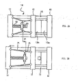
Fig. 2A and Fig. 2B are figures for explaining generation of a mold clamping force caused by the toggle typemold clamping system 1. -
Fig. 2A shows a state in which themovable mold half 13b and the fixedmold half 13a touch each other in a state in which thetoggle mechanism 14 of the toggle typemold clamping system 1 is contracted. When changing from the state shown inFig. 2A to a lock-up state in which thetoggle mechanism 14 is stretched by rotating the servomotor for mold clamping 18 to rotate theball screw 19, and moving thecrosshead 20 forward as far as a distance P (i.e. by arranging afirst link 25 and asecond link 26 in a single straight line), the state shown inFig. 2B is reached. In this state, thetie bar 15 provided between the fixedplaten 10 and therear platen 11 is completely stretched, whereby themold halves - Although the
mold halves Fig. 2A touch each other, a mold clamping force is not generated, thus thetie bar 15 is not stretched. Furthermore, if thetoggle mechanism 14 is bent to the extent which allows generation of a mold clamping force set by thetoggle mechanism 14 ofFig. 2A (i.e. as long as the position of thecrosshead 20 or the position of themovable platen 12 with respect to therear platen 11 is placed in-positions necessary to generate the set mold clamping force), a mold clamping force as is set can be generated when the toggle mechanism is brought to the state shown inFig. 2B (lock-up state) from the state shown inFig. 2A (mold touch state). - However, if the
tie bar 15 is already stretched in the mold touch state inFig. 2A and a molding clamping force is generated to some extent, a mold clamping force as is set is not obtained even if the toggle mechanism is stretched and brought from the above state to the lock-up state ofFig. 2B , whereby a mold clamping force that is larger than the set mold clamping force is generated. - Practically, it is difficult to obtain a "0" mold clamping force in a mold touch position shown in
Fig. 2A . In other words, it is practically difficult to operate thetoggle mechanism 14 and to position themovable platen 12 in the mold touch position shown inFig. 2A without pressing themold half 13b attached to themovable platen 12 against themold half 13a attached to the fixedplaten 10. - With this point in view, the present invention therefore is contrived such that the amount of stretch (generated mold clamping force) of the
tie bar 15 in the mold touch position is obtained in advance as a correction amount, and an accurate set mold clamping force is obtained by using this correction amount when carrying out mold clamping force adjustment. -
Fig. 3A to Fig. 3D are figures for explaining a mold clamping force adjustment operation in an embodiment of the mold clamping force adjustment device according to the present invention. - As shown in
Fig. 3A , themold halves platen 10 and themovable platen 12 respectively. The servomotor for mold clamping 18 is driven, theball screw 19 is rotated, and thetoggle mechanism 14 is contracted, whereby themovable platen 12 is positioned in the position which is necessary to generate the set mold clamping force. Here, determining a position of themovable platen 12 is the same as determining positions of the servomotor for mold clamping 18,crosshead 20, andmovable mold half 13b. Suppose that the distance between therear platen 11 and themovable platen 12 at this time is "W". - As shown in
Fig. 3B , while holding the distance W between therear platen 11 and the movable platen 12 (i.e. while holding the position of theservomotor 18 for mold clamping), the motor formold thickness adjustment 17 is driven, therear platen 11 is moved forward, and themovable mold half 13b is brought into contact with the fixedmold half 13a. When this mold touch is detected, driving the motor formold thickness adjustment 17 is stopped. - This mold touch is detected by a generation of an overload signal (excess current signal) from the
inverter 36 which drives the motor formold thickness adjustment 17. The fact that the mold halves touch each other and an overload signal (excess current signal) is generated from theinverter 36 means that the mold halves are pressed by a force corresponding to this overload signal (excess current signal) to stretch thetie bar 15, and a mold clamping force is generated. Since the force applied to themold halves tie bar 15 becomes constant when an overload signal (excess current signal) is generated from theinverter 36 and the drive of the motor formold thickness adjustment 17 is stopped. - Next, as shown in
Fig. 3C , themovable mold half 13b is separated from the fixedmold half 13a by driving the servomotor for mold clamping 18, rotating theball screw 19, contracting thetoggle mechanism 14, and making the distance between therear platen 11 and themovable platen 12 shorter than the distance W corresponding to the set mold clamping force. By opening the mold as above, there no longer exists the mold clamping force and the stretch of thetie bar 15, and as a result, thetie bar 15 extending as much as ΔL inFig. 2B is contracted as far as ΔL. At this time, therear platen 11 joined with thetie bar 15 by screws is moved forward as far as ΔL. - Here, as shown in
Fig. 3D , the motor formold thickness adjustment 17 is driven to move therear platen 11 backward as far as the amount of stretch ΔL of thetie bar 15 at the time of the mold touch. Accordingly, positioning therear platen 11 is completed, thereby completing the mold clamping force adjustment operation. - As described above, first the
rear platen 11 is moved forward while keeping the distance W (corresponds to the set mold clamping force) between therear platen 11 and themovable platen 12 to conduct mold touch (Fig. 3B ). Then, therear platen 11 is moved backward, from its current position, as far as the amount of stretch ΔL of thetie bar 15 obtained in the previous mold touch. - By doing so, by driving the servomotor for mold clamping 18, rotating the
ball screw 19, stretching thetoggle mechanism 14, and move themovable platen 12 forward in the adjusted position of therear platen 11, when mold touch occurs and few mold clamping force is still generated, the distance between therear platen 11 and themovable platen 12 becomes the value W which is necessary to provide a set mold clamping force. Therefore, by stretching thetoggle mechanism 14 to be brought to the lock-up state in the adjusted position of therear platen 11, a mold clamping force with a value accurately corresponding to the distance between therear platen 11 and themovable platen 12 is generated. -
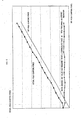
Fig. 5 is a graph showing a relationship between the amount of a movement of a crosshead 20 (corresponds to the amount of movement of the servomotor for mold clamping) from the time of mold touch (Fig. 2A ) to the lock-up time (Fig. 2B ) of thetoggle mechanism 14 and a generated mold clamping force. If a mold clamping force to be generated with respect to the selectedmold halves crosshead 20 which is necessary to provide the set mold clamping force can be obtained from this graph. The amount of movement of thecrosshead 20 is stored in a form of the amount of movement of the servomotor for mold clamping in a predetermined region in theRAM 38 of thecontroller 2. Further, a worker may set and input the amount of movement of the crosshead in accordance with the set mold clamping force by using the graph of this relationship. - When driving the motor for
mold thickness adjustment 17, moving therear platen 11 and themovable platen 12, and pressing themovable mold half 13b against the fixedmold half 13a (Fig. 3B ), an overload signal (excess current signal) is generated from theinverter 36. The stretch of thetie bar 15 at the time when this overload signal is detected, i.e. the amount of stretch ΔL shown inFig. 3B , is obtained in an experiment in advance. Furthermore, a drive time ΔT of the motor formold thickness adjustment 17 necessary to move therear platen 11 backward as much as the amount of stretch ΔL is obtained in an experiment in advance and stored in thecontroller 2. -
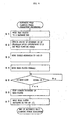
Fig. 4 is a flow chart showing a mold clamping adjustment work. - When a mold clamping force adjustment command is input, the
processor 30 of thecontroller 2 activates the motor formold thickness adjustment 17 through the input-output circuit 35 (Fig. 1 ) to move therear platen 11 backward to a set backward end (Step S1). Next, an amount of movement CP of thecrosshead 20, which is necessary to provide a set mold clamping force, is obtained by means of the data of the relationship (Fig. 5 ) between the amount of movement of thecrosshead 20 of the toggle mechanism and the generated mold clamping force (Step S2). Then the servomotor for mold clamping 18 is driven and thecrosshead 20 is moved to CP (Step S3). Due to this movement of thecrosshead 20, themovable platen 12 is moved toward therear platen 11, whereby the distance between themovable platen 12 and therear platen 11 becomes the distance W corresponding to the set mold clamping force (Fig. 3A ). - Next, the motor for
mold thickness adjustment 17 is driven and therear platen 11 is moved forward (Step S4). Then, it is monitored whether or not an overload signal (excess current signal) is generated from theinverter 36 which drives the motor 17 (Step S5). If an overload signal (excess current signal) is detected, the drive of the motor formold thickness adjustment 17 is stopped to stop the forward movement of the rear platen 11 (Step S6). In this state thetie bar 15 is stretched as much as ΔL, as shown inFig. 3B . - Next, the motor for
mold thickness adjustment 17 is driven for a period of time ΔT, which is set, and therear platen 11 is moved backward as much as the distance ΔL (Step S7). Accordingly, the distance between therear platen 11 and themovable platen 12 becomes the distance W corresponding to the set mold clamping force when mold touch occurs (also when less mold clamping force is generated). Consequently, the mold clamping force adjustment work is finished. -
Fig. 6 andFig. 7 show results of experiment for confirming the effects of the present invention with respect to the conventional technologies. - In
Fig. 6 (conventional technology), an arbitrary mold clamping force is set, and the motor formold thickness adjustment 17 is operated to move therear platen 11 forward in a state in which thetoggle mechanism 14 is contracted as much as the amount corresponding to the set mold clamping force, and mold touch is detected. When mold touch is detected, therear platen 11 is stopped, and thereafter the toggle mechanism is driven to move themovable platen 12 forward to a lock-up position. Then, when the toggle mechanism is in the lock-up position the mold clamping force is actually measured. An "actual mold clamping force" inFig. 6 means a mold clamping force obtained by actually measuring the mold clamping force. - As shown in
Fig. 6 , there is generally a substantially constant difference between the set mold clamping force and the mold clamping force that is actually generated, where the actual mold clamping force exceeds the set mold clamping force. - On the other hand,
Fig. 7 is an experimental result when performing a correction according to the present invention. Specifically, an arbitrary mold clamping force is set, and the motor formold thickness adjustment 17 is operated to move therear platen 11 forward in a state in which the toggle mechanism is contracted corresponding amount with respect to the set mold clamping force, and mold touch is detected. When mold touch is detected, the forward movement of therear platen 11 is stopped. Thereafter, therear platen 11 is moved a preset correction amount ΔL backward from the stop position. Consequently, positioning of therear platen 11 is finished. Next, thetoggle mechanism 14 is driven to move themovable platen 12 forward to reach a lock-up position, and a mold clamping force at this time is detected. Through this series of works, it is found that the actual mold clamping force is substantially equated with the set mold clamping force. - In the embodiment described above, the fact that the mold halves touched each other is detected by means of an overload signal (excess current signal) outputted from the inverter. However, in the case of driving the
rear platen 11 by using the geared motor, the mold touch may be detected by means of a current excess signal generated from a thermal relay incorporated in a geared motor drive circuit. Moreover, when driving therear platen 11 by using a hydraulic mechanism, mold touch may be detected by a pressure increase signal which indicates that the pressure from a hydraulic system has reached a predetermined level. In any of the detection methods, the suppress strength of the mold halves when a mold touch detection signal is outputted is constant regardless of the thicknesses of the mold halves, thus the stretch of thetie bar 15 corresponding to this constant suppress strength is a constant amount of ΔL, which may be taken as the correction amount. - Moreover, in the present embodiment, the amount of backward movement of the
rear platen 11 is determined by a time in Step S7 ofFig. 4 . However, if the position sensor for detecting the position of therear platen 11 is provided, the amount of backward movement ΔL of therear platen 11 may be determined not by a time but by the amount of movement detected by the position sensor. - Furthermore, in the embodiment described above, the
toggle mechanism 14 is contracted as necessary to provide a set mold clamping force (i.e. thetoggle mechanism 14 is positioned to a place where thecrosshead 20 is moved as much as CP (see Step S2 inFig. 4 ) backward from the lock-up position), and therear platen 11 is moved forward to cause mold touch. - However, with the mold thickness adjustment mechanism that comprises a position sensor for detecting the position of the
rear platen 11, and the like, thetoggle mechanism 14 does not necessarily have to be contracted as much as to be equivalent to the set mold clamping force. For example, therear platen 11 is moved forward to cause mold touch while stretching thetoggle mechanism 14 to the lock-up state, and therear platen 11 may be moved backward as much as the amount of stretch ΔL (constant regardless of the state of the toggle mechanism 14) of thetie bar 15 at the time of the mold touch. Accordingly, the state of mold touch can be obtained in a state in which little stretch of thetie bar 15 is observed. Then, after thetoggle mechanism 14 is contracted, therear platen 11 is moved forward by the distance corresponding to the set mold clamping force. When therear platen 11 is adjusted to this position, thetoggle mechanism 14 is brought from its contracted state to the lock-up state, whereby a mold clamping force as is set can be obtained. - In addition, as long as the toggle type mold clamping system comprises the position sensor for detecting the amount of movement of the
rear platen 11 and obtains the distance between therear platen 11 and themovable platen 12 by means of calculation using the position sensor or the position/speed detector 24, the stretch of thetoggle mechanism 14 at the time of mold touch may be in any extent. A distance W1 between therear platen 11 and themovable platen 12 at the time when the mold touch each other in an arbitrary contraction state of thetoggle mechanism 14 is obtained by the position sensor or the position/speed detector 24. Next, the relationship data is used to obtain a distance W0 between therear platen 11 and themovable platen 12 in a state in which the toggle mechanism is contracted as much as to be equivalent to the set mold clamping force. After moving therear platen 11 backward as much as the amount of stretch ΔL of thetie bar 15 from the mold touch, therear platen 11 is moved the amount of movement of W0 and W1, whereby the set mold clamping force can be obtained.
Claims (4)
- A mold clamping force adjustment method of a toggle type injection molding machine, the method characterised by comprising the steps of:moving a rear platen (11) of the molding machine forward in a state in which a toggle mechanism (14) of a toggle type mold clamping system (1) of the molding machine is contracted as much as an amount (Cp) corresponding to a mold clamping force which is set in advance;detecting when a movable mold half (13b) touches a fixed mold half (13a) of the molding machine; andwhen it is detected that the movable mold half (13b) touches the fixed mold half (13a), moving the rear platen (11) backward as much as an amount (ΔL) corresponding to a compressive force generated when the movable mold half (13b) touches the fixed mold half (13a).
- A mold clamping force adjustment method of a toggle type injection molding machine, the method comprising steps of:moving a rear platen (11) of the molding machine forward, in a state in which a toggle mechanism (14) of a toggle type mold clamping system (1) of the molding machine is stretched;detecting when a movable mold half (13b) touches a fixed mold half (13a) of the molding machine; the method characterised bywhen it is detected that the movable mold half (13b) touches the fixed mold half (13a), moving the rear platen (11) backward as much as an amount (ΔL) corresponding to a compressive force generated when the movable mold half (13b) touches the fixed mold half (13a) and contracting the toggle mechanism (14) to reach an arbitrary state; andmoving the rear platen (11) forward by an amount (Cp) corresponding to a set mold clamping force.
- The mold clamping force adjustment method of claim 1 or 2, wherein the amount of backward movement of said rear platen (11) is controlled by detecting the position of the rear platen.
- The mold clamping force adjustment method of claim 1 or 2, wherein the amount of backward movement of said rear platen (11) is adjusted using a period of time (AT) for moving the rear platen backward.
Applications Claiming Priority (2)
| Application Number | Priority Date | Filing Date | Title |
|---|---|---|---|
| JP2004095907A JP3962725B2 (en) | 2004-03-29 | 2004-03-29 | Clamping force adjusting device for toggle type injection molding machine |
| JP2004095907 | 2004-03-29 |
Publications (2)
| Publication Number | Publication Date |
|---|---|
| EP1584445A1 EP1584445A1 (en) | 2005-10-12 |
| EP1584445B1 true EP1584445B1 (en) | 2008-08-13 |
Family
ID=34909431
Family Applications (1)
| Application Number | Title | Priority Date | Filing Date |
|---|---|---|---|
| EP05251779A Expired - Fee Related EP1584445B1 (en) | 2004-03-29 | 2005-03-23 | Mold clamping force adjustment method of toggle type injection molding machine |
Country Status (5)
| Country | Link |
|---|---|
| US (1) | US7210918B2 (en) |
| EP (1) | EP1584445B1 (en) |
| JP (1) | JP3962725B2 (en) |
| CN (1) | CN1676303A (en) |
| DE (1) | DE602005008798D1 (en) |
Families Citing this family (27)
| Publication number | Priority date | Publication date | Assignee | Title |
|---|---|---|---|---|
| JP4477546B2 (en) * | 2005-06-02 | 2010-06-09 | 住友重機械工業株式会社 | Molding condition setting method |
| JP4836742B2 (en) * | 2006-10-10 | 2011-12-14 | 株式会社ダイセン工業 | Foam molding machine and operation method thereof |
| JP4836611B2 (en) * | 2006-03-02 | 2011-12-14 | 株式会社ダイセン工業 | Operation method of foamed resin molding machine |
| US8097192B2 (en) | 2006-03-02 | 2012-01-17 | Daisen Industry Co., Ltd. | Foamed resin molding machine and method of operating the same |
| US20090005157A1 (en) * | 2007-06-28 | 2009-01-01 | Netley Neil J | Electronic funds transfer system and method of use in gaming environment |
| DE102007043673B4 (en) * | 2007-09-13 | 2009-10-15 | Adcuram Maschinenbauholding Gmbh | Method for safely closing a tool |
| JP5377905B2 (en) * | 2008-08-11 | 2013-12-25 | ポリプラスチックス株式会社 | Mold, molded product evaluation method, and molding condition determination method |
| JP4787894B2 (en) * | 2009-07-23 | 2011-10-05 | 日精樹脂工業株式会社 | Mold thickness adjustment method for toggle type mold clamping device |
| JP2011183705A (en) * | 2010-03-09 | 2011-09-22 | Sumitomo Heavy Ind Ltd | Injection molding machine and injection molding method |
| TW201228799A (en) * | 2011-01-07 | 2012-07-16 | Acumen Co Ltd | Electrical injection molding machine |
| JP2013126722A (en) * | 2011-12-16 | 2013-06-27 | Sumitomo Heavy Ind Ltd | Injection molding machine |
| CN102922710B (en) * | 2012-11-08 | 2015-03-25 | 广西柳州中嘉知识产权服务有限公司 | Plastic injection molding machine |
| JP5596105B2 (en) * | 2012-11-09 | 2014-09-24 | ファナック株式会社 | Mold thickness adjusting device for injection molding machine |
| JP5800289B2 (en) * | 2013-02-26 | 2015-10-28 | 村田機械株式会社 | Clamping device management system |
| BE1021675B1 (en) * | 2013-04-26 | 2016-01-05 | Gb Boucherie Nv | INJECTION MOLDING |
| JP5734366B2 (en) | 2013-07-26 | 2015-06-17 | ファナック株式会社 | Clamping force measuring mechanism of injection molding machine |
| CN104802380B (en) * | 2014-01-24 | 2018-10-26 | 东芝机械株式会社 | Forming machine and its driving method |
| JP6505403B2 (en) * | 2014-03-13 | 2019-04-24 | 住友重機械工業株式会社 | Injection molding machine, information processing apparatus for injection molding machine, and information processing method for injection molding machine |
| CN104302460B (en) * | 2014-03-18 | 2016-08-31 | Ykk株式会社 | Injection (mo(u)lding) machine |
| KR101972477B1 (en) * | 2014-12-24 | 2019-04-25 | 엘에스엠트론 주식회사 | Injection molding machine and method for controlling the mold height of the injection molding machine |
| CN108698292B (en) * | 2016-03-25 | 2021-04-09 | 住友重机械工业株式会社 | Injection molding machine |
| JP6751037B2 (en) * | 2017-02-28 | 2020-09-02 | 住友重機械工業株式会社 | Injection molding machine |
| CN107263835A (en) * | 2017-07-13 | 2017-10-20 | 江苏联宇医疗器械有限公司 | A kind of pharmaceutical injection machine |
| JP7152243B2 (en) * | 2018-10-17 | 2022-10-12 | 住友重機械工業株式会社 | Injection molding machine |
| JP7132080B2 (en) * | 2018-10-17 | 2022-09-06 | 住友重機械工業株式会社 | Injection molding machine |
| JP6876086B2 (en) * | 2019-04-01 | 2021-05-26 | 日精樹脂工業株式会社 | Injection molding machine equipped with an operation setting device |
| CN110497593B (en) * | 2019-09-17 | 2021-12-07 | 宁波市北仑复力机械有限公司 | Operation method of injection molding machine |
Family Cites Families (16)
| Publication number | Priority date | Publication date | Assignee | Title |
|---|---|---|---|---|
| DE1558277A1 (en) * | 1967-07-26 | 1970-03-19 | Mahle Werk Gmbh | Device for regulating the closing pressure of mold holding presses for die casting machines operated by toggle levers |
| US3819774A (en) * | 1968-05-09 | 1974-06-25 | Buehler Ag Geb | Method for controlling operation of a press |
| DE2020053A1 (en) * | 1970-04-24 | 1971-11-04 | Krauss Maffei Ag | Thermoplastic resin injection moulding machine control device |
| US3840313A (en) * | 1972-11-01 | 1974-10-08 | Litton Industrial Products | Molding machine clamp force indicator |
| US4301100A (en) * | 1979-10-01 | 1981-11-17 | Package Machinery Company | Method and apparatus for setting a clamping load |
| JPS62220314A (en) | 1986-03-22 | 1987-09-28 | Fanuc Ltd | Injection molding machine provided with automatic mold thickness adjuster by means of geared motor |
| US4685876A (en) * | 1986-03-24 | 1987-08-11 | Cincinnati Milacron Inc. | Toggle injection molding clamping force monitor |
| JPH0825213B2 (en) * | 1992-02-10 | 1996-03-13 | 株式会社新潟鉄工所 | Mold clamping force adjustment method in electric injection molding machine |
| WO1993025368A1 (en) * | 1992-06-09 | 1993-12-23 | Klöckner Ferromatik Desma Gmbh | Process for adjusting the height of tools of bent lever closure systems, in particular in injection moulding machines |
| JP2783124B2 (en) | 1993-06-28 | 1998-08-06 | 三菱電機株式会社 | Temperature control method for hot rolled steel |
| JP2798171B2 (en) * | 1993-09-28 | 1998-09-17 | 宇部興産株式会社 | Method of detecting mold clamping force of mold clamping device |
| US5945047A (en) * | 1997-03-13 | 1999-08-31 | The Japan Steel Works, Ltd. | Method of injection-compression molding |
| JP3729975B2 (en) | 1997-04-04 | 2005-12-21 | 株式会社日本製鋼所 | Clamping force setting method for toggle type injection molding machine |
| JP3581061B2 (en) * | 1999-10-29 | 2004-10-27 | 東芝機械株式会社 | Method and apparatus for adjusting mold thickness of injection molding machine |
| US6595766B2 (en) * | 2000-01-28 | 2003-07-22 | Toshiba Kikai Kabushiki Kaisha | Die clamping apparatus, die clamping force measurement method and die clamping force adjustment method |
| JP3822774B2 (en) * | 2000-03-02 | 2006-09-20 | 株式会社日本製鋼所 | Clamping force adjustment method for toggle injection molding machine |
-
2004
- 2004-03-29 JP JP2004095907A patent/JP3962725B2/en not_active Expired - Fee Related
-
2005
- 2005-03-23 DE DE602005008798T patent/DE602005008798D1/en not_active Expired - Fee Related
- 2005-03-23 EP EP05251779A patent/EP1584445B1/en not_active Expired - Fee Related
- 2005-03-28 CN CN200510058808.6A patent/CN1676303A/en active Pending
- 2005-03-29 US US11/092,588 patent/US7210918B2/en not_active Expired - Fee Related
Also Published As
| Publication number | Publication date |
|---|---|
| JP3962725B2 (en) | 2007-08-22 |
| US20050214407A1 (en) | 2005-09-29 |
| US7210918B2 (en) | 2007-05-01 |
| CN1676303A (en) | 2005-10-05 |
| EP1584445A1 (en) | 2005-10-12 |
| DE602005008798D1 (en) | 2008-09-25 |
| JP2005280047A (en) | 2005-10-13 |
Similar Documents
| Publication | Publication Date | Title |
|---|---|---|
| EP1584445B1 (en) | Mold clamping force adjustment method of toggle type injection molding machine | |
| EP1645395B1 (en) | Controller of injection molding machine | |
| JP3694684B2 (en) | Injection molding machine | |
| CN101111359B (en) | Molding condition setting method and method of controlling injection molding machine | |
| JP4272205B2 (en) | Control method of injection molding machine | |
| JP4477546B2 (en) | Molding condition setting method | |
| US7892463B2 (en) | Mold clamping force correction method for mold clamping apparatus | |
| JP4568350B2 (en) | Abnormality detection device for injection molding machine | |
| US7287971B2 (en) | Load determining device for an electrically-operated injection molding machine | |
| JP4410749B2 (en) | Mold thickness adjustment method for toggle type mold clamping device | |
| JP2010162558A (en) | Bending machine | |
| JP4689559B2 (en) | Mold clamping device and mold clamping device control method | |
| JPH0661806B2 (en) | Automatic clamping force setting method for toggle type clamping device | |
| JP4231474B2 (en) | Clamping method of toggle type mold clamping device | |
| JP2668599B2 (en) | Method and apparatus for automatically adjusting thickness of injection molding machine | |
| JP4727477B2 (en) | Clamping force control method | |
| JP4313259B2 (en) | Mold thickness adjustment method for toggle type mold clamping device | |
| JP2814262B2 (en) | Automatic mold thickness adjustment method | |
| JP4724050B2 (en) | Mold clamping control method of injection molding machine | |
| JP6077427B2 (en) | Control device and control method for injection molding machine | |
| JP2709868B2 (en) | Die height adjustment method | |
| JP4964313B2 (en) | Molding condition setting method and mold clamping device | |
| JP2678700B2 (en) | Method of measuring mold thickness of injection molding machine | |
| JPH072334B2 (en) | Automatic clamping force setting method for toggle type clamping device | |
| JP2001277248A (en) | Mold clamping device, method for measuring mold clamping force, and method for adjusting mold clamping force |
Legal Events
| Date | Code | Title | Description |
|---|---|---|---|
| PUAI | Public reference made under article 153(3) epc to a published international application that has entered the european phase |
Free format text: ORIGINAL CODE: 0009012 |
|
| AK | Designated contracting states |
Kind code of ref document: A1 Designated state(s): AT BE BG CH CY CZ DE DK EE ES FI FR GB GR HU IE IS IT LI LT LU MC NL PL PT RO SE SI SK TR |
|
| AX | Request for extension of the european patent |
Extension state: AL BA HR LV MK YU |
|
| 17P | Request for examination filed |
Effective date: 20060320 |
|
| AKX | Designation fees paid |
Designated state(s): DE |
|
| RTI1 | Title (correction) |
Free format text: MOLD CLAMPING FORCE ADJUSTMENT METHOD OF TOGGLE TYPE INJECTION MOLDING MACHINE |
|
| GRAP | Despatch of communication of intention to grant a patent |
Free format text: ORIGINAL CODE: EPIDOSNIGR1 |
|
| GRAS | Grant fee paid |
Free format text: ORIGINAL CODE: EPIDOSNIGR3 |
|
| GRAA | (expected) grant |
Free format text: ORIGINAL CODE: 0009210 |
|
| AK | Designated contracting states |
Kind code of ref document: B1 Designated state(s): DE |
|
| REF | Corresponds to: |
Ref document number: 602005008798 Country of ref document: DE Date of ref document: 20080925 Kind code of ref document: P |
|
| PLBE | No opposition filed within time limit |
Free format text: ORIGINAL CODE: 0009261 |
|
| STAA | Information on the status of an ep patent application or granted ep patent |
Free format text: STATUS: NO OPPOSITION FILED WITHIN TIME LIMIT |
|
| 26N | No opposition filed |
Effective date: 20090514 |
|
| PGFP | Annual fee paid to national office [announced via postgrant information from national office to epo] |
Ref country code: DE Payment date: 20090319 Year of fee payment: 5 |
|
| PG25 | Lapsed in a contracting state [announced via postgrant information from national office to epo] |
Ref country code: DE Free format text: LAPSE BECAUSE OF NON-PAYMENT OF DUE FEES Effective date: 20101001 |