EP1582329A1 - Mikrovorsprungsstruktur und deren herstellungsverfahren - Google Patents
Mikrovorsprungsstruktur und deren herstellungsverfahren Download PDFInfo
- Publication number
- EP1582329A1 EP1582329A1 EP03775925A EP03775925A EP1582329A1 EP 1582329 A1 EP1582329 A1 EP 1582329A1 EP 03775925 A EP03775925 A EP 03775925A EP 03775925 A EP03775925 A EP 03775925A EP 1582329 A1 EP1582329 A1 EP 1582329A1
- Authority
- EP
- European Patent Office
- Prior art keywords
- micro
- pillar structure
- pillars
- polymer
- structure according
- Prior art date
- Legal status (The legal status is an assumption and is not a legal conclusion. Google has not performed a legal analysis and makes no representation as to the accuracy of the status listed.)
- Withdrawn
Links
- 238000000034 method Methods 0.000 title description 20
- 230000008569 process Effects 0.000 title description 19
- 229920000642 polymer Polymers 0.000 claims abstract description 79
- 239000000758 substrate Substances 0.000 claims abstract description 42
- 239000003960 organic solvent Substances 0.000 claims abstract description 32
- 230000002209 hydrophobic effect Effects 0.000 claims abstract description 25
- 239000012298 atmosphere Substances 0.000 claims abstract description 24
- 239000010409 thin film Substances 0.000 claims description 46
- XLYOFNOQVPJJNP-UHFFFAOYSA-N water Substances O XLYOFNOQVPJJNP-UHFFFAOYSA-N 0.000 claims description 44
- 206010040844 Skin exfoliation Diseases 0.000 claims description 42
- 238000004519 manufacturing process Methods 0.000 claims description 27
- 239000004793 Polystyrene Substances 0.000 claims description 21
- 229920002223 polystyrene Polymers 0.000 claims description 21
- 229920002988 biodegradable polymer Polymers 0.000 claims description 17
- 239000004621 biodegradable polymer Substances 0.000 claims description 17
- 229920001600 hydrophobic polymer Polymers 0.000 claims description 17
- 239000002390 adhesive tape Substances 0.000 claims description 15
- 239000002243 precursor Substances 0.000 claims description 14
- 239000004417 polycarbonate Substances 0.000 claims description 11
- 229920000515 polycarbonate Polymers 0.000 claims description 11
- 238000001704 evaporation Methods 0.000 claims description 10
- 230000008020 evaporation Effects 0.000 claims description 10
- CBENFWSGALASAD-UHFFFAOYSA-N Ozone Chemical compound [O-][O+]=O CBENFWSGALASAD-UHFFFAOYSA-N 0.000 claims description 7
- 239000003607 modifier Substances 0.000 claims description 6
- 239000005871 repellent Substances 0.000 claims description 6
- 238000010008 shearing Methods 0.000 claims description 6
- 238000007664 blowing Methods 0.000 claims description 5
- 230000005660 hydrophilic surface Effects 0.000 claims description 5
- 238000004090 dissolution Methods 0.000 claims description 4
- 229920000728 polyester Polymers 0.000 claims description 4
- 229920000193 polymethacrylate Polymers 0.000 claims description 4
- 238000007385 chemical modification Methods 0.000 claims description 3
- 238000007254 oxidation reaction Methods 0.000 claims description 3
- 239000003513 alkali Substances 0.000 claims description 2
- 230000008901 benefit Effects 0.000 abstract description 10
- 238000011161 development Methods 0.000 abstract description 4
- 230000018109 developmental process Effects 0.000 abstract description 4
- 230000001788 irregular Effects 0.000 abstract description 3
- 239000000243 solution Substances 0.000 description 65
- 239000010408 film Substances 0.000 description 64
- 239000000463 material Substances 0.000 description 50
- HEDRZPFGACZZDS-UHFFFAOYSA-N Chloroform Chemical compound ClC(Cl)Cl HEDRZPFGACZZDS-UHFFFAOYSA-N 0.000 description 38
- -1 separators Substances 0.000 description 31
- 239000002904 solvent Substances 0.000 description 17
- 238000001878 scanning electron micrograph Methods 0.000 description 13
- 239000011521 glass Substances 0.000 description 12
- 230000003068 static effect Effects 0.000 description 11
- 239000007788 liquid Substances 0.000 description 10
- 229920002401 polyacrylamide Polymers 0.000 description 10
- 230000000052 comparative effect Effects 0.000 description 9
- 239000011148 porous material Substances 0.000 description 9
- GWEVSGVZZGPLCZ-UHFFFAOYSA-N Titan oxide Chemical compound O=[Ti]=O GWEVSGVZZGPLCZ-UHFFFAOYSA-N 0.000 description 8
- 238000004113 cell culture Methods 0.000 description 8
- 239000007787 solid Substances 0.000 description 7
- 150000001875 compounds Chemical class 0.000 description 6
- 238000005459 micromachining Methods 0.000 description 5
- 238000000018 DNA microarray Methods 0.000 description 4
- 238000005266 casting Methods 0.000 description 4
- 238000006243 chemical reaction Methods 0.000 description 4
- 238000001035 drying Methods 0.000 description 4
- 239000000499 gel Substances 0.000 description 4
- 239000000203 mixture Substances 0.000 description 4
- 230000003287 optical effect Effects 0.000 description 4
- 229920000747 poly(lactic acid) Polymers 0.000 description 4
- 229920003229 poly(methyl methacrylate) Polymers 0.000 description 4
- 229920001610 polycaprolactone Polymers 0.000 description 4
- 239000004626 polylactic acid Substances 0.000 description 4
- 238000002360 preparation method Methods 0.000 description 4
- 239000004065 semiconductor Substances 0.000 description 4
- UHOVQNZJYSORNB-UHFFFAOYSA-N Benzene Chemical compound C1=CC=CC=C1 UHOVQNZJYSORNB-UHFFFAOYSA-N 0.000 description 3
- QGJOPFRUJISHPQ-UHFFFAOYSA-N Carbon disulfide Chemical compound S=C=S QGJOPFRUJISHPQ-UHFFFAOYSA-N 0.000 description 3
- YMWUJEATGCHHMB-UHFFFAOYSA-N Dichloromethane Chemical compound ClCCl YMWUJEATGCHHMB-UHFFFAOYSA-N 0.000 description 3
- XEKOWRVHYACXOJ-UHFFFAOYSA-N Ethyl acetate Chemical compound CCOC(C)=O XEKOWRVHYACXOJ-UHFFFAOYSA-N 0.000 description 3
- CERQOIWHTDAKMF-UHFFFAOYSA-M Methacrylate Chemical compound CC(=C)C([O-])=O CERQOIWHTDAKMF-UHFFFAOYSA-M 0.000 description 3
- OKKJLVBELUTLKV-UHFFFAOYSA-N Methanol Chemical compound OC OKKJLVBELUTLKV-UHFFFAOYSA-N 0.000 description 3
- HEMHJVSKTPXQMS-UHFFFAOYSA-M Sodium hydroxide Chemical compound [OH-].[Na+] HEMHJVSKTPXQMS-UHFFFAOYSA-M 0.000 description 3
- YXFVVABEGXRONW-UHFFFAOYSA-N Toluene Chemical compound CC1=CC=CC=C1 YXFVVABEGXRONW-UHFFFAOYSA-N 0.000 description 3
- 230000015572 biosynthetic process Effects 0.000 description 3
- 125000003178 carboxy group Chemical group [H]OC(*)=O 0.000 description 3
- 239000011248 coating agent Substances 0.000 description 3
- 238000000576 coating method Methods 0.000 description 3
- 230000003247 decreasing effect Effects 0.000 description 3
- 238000005516 engineering process Methods 0.000 description 3
- 239000003014 ion exchange membrane Substances 0.000 description 3
- 239000004926 polymethyl methacrylate Substances 0.000 description 3
- BDERNNFJNOPAEC-UHFFFAOYSA-N propan-1-ol Chemical compound CCCO BDERNNFJNOPAEC-UHFFFAOYSA-N 0.000 description 3
- 102000004169 proteins and genes Human genes 0.000 description 3
- 108090000623 proteins and genes Proteins 0.000 description 3
- 238000000926 separation method Methods 0.000 description 3
- 239000010936 titanium Substances 0.000 description 3
- 229910052719 titanium Inorganic materials 0.000 description 3
- GUBGYTABKSRVRQ-XLOQQCSPSA-N Alpha-Lactose Chemical compound O[C@@H]1[C@@H](O)[C@@H](O)[C@@H](CO)O[C@H]1O[C@@H]1[C@@H](CO)O[C@H](O)[C@H](O)[C@H]1O GUBGYTABKSRVRQ-XLOQQCSPSA-N 0.000 description 2
- XKRFYHLGVUSROY-UHFFFAOYSA-N Argon Chemical compound [Ar] XKRFYHLGVUSROY-UHFFFAOYSA-N 0.000 description 2
- IJGRMHOSHXDMSA-UHFFFAOYSA-N Atomic nitrogen Chemical compound N#N IJGRMHOSHXDMSA-UHFFFAOYSA-N 0.000 description 2
- LFQSCWFLJHTTHZ-UHFFFAOYSA-N Ethanol Chemical compound CCO LFQSCWFLJHTTHZ-UHFFFAOYSA-N 0.000 description 2
- HTTJABKRGRZYRN-UHFFFAOYSA-N Heparin Chemical compound OC1C(NC(=O)C)C(O)OC(COS(O)(=O)=O)C1OC1C(OS(O)(=O)=O)C(O)C(OC2C(C(OS(O)(=O)=O)C(OC3C(C(O)C(O)C(O3)C(O)=O)OS(O)(=O)=O)C(CO)O2)NS(O)(=O)=O)C(C(O)=O)O1 HTTJABKRGRZYRN-UHFFFAOYSA-N 0.000 description 2
- GUBGYTABKSRVRQ-QKKXKWKRSA-N Lactose Natural products OC[C@H]1O[C@@H](O[C@H]2[C@H](O)[C@@H](O)C(O)O[C@@H]2CO)[C@H](O)[C@@H](O)[C@H]1O GUBGYTABKSRVRQ-QKKXKWKRSA-N 0.000 description 2
- 239000004698 Polyethylene Substances 0.000 description 2
- 125000005210 alkyl ammonium group Chemical group 0.000 description 2
- 239000000969 carrier Substances 0.000 description 2
- 239000003054 catalyst Substances 0.000 description 2
- 238000009833 condensation Methods 0.000 description 2
- 230000005494 condensation Effects 0.000 description 2
- 239000004020 conductor Substances 0.000 description 2
- 238000000151 deposition Methods 0.000 description 2
- 229960000633 dextran sulfate Drugs 0.000 description 2
- 238000003745 diagnosis Methods 0.000 description 2
- 239000012153 distilled water Substances 0.000 description 2
- 125000003438 dodecyl group Chemical group [H]C([H])([H])C([H])([H])C([H])([H])C([H])([H])C([H])([H])C([H])([H])C([H])([H])C([H])([H])C([H])([H])C([H])([H])C([H])([H])C([H])([H])* 0.000 description 2
- 230000000694 effects Effects 0.000 description 2
- 230000012010 growth Effects 0.000 description 2
- 229920000669 heparin Polymers 0.000 description 2
- 229960002897 heparin Drugs 0.000 description 2
- 238000007654 immersion Methods 0.000 description 2
- 239000008101 lactose Substances 0.000 description 2
- 238000005191 phase separation Methods 0.000 description 2
- 229920002492 poly(sulfone) Polymers 0.000 description 2
- 229920000573 polyethylene Polymers 0.000 description 2
- 238000003672 processing method Methods 0.000 description 2
- 230000002940 repellent Effects 0.000 description 2
- 239000000126 substance Substances 0.000 description 2
- 238000005406 washing Methods 0.000 description 2
- SCYULBFZEHDVBN-UHFFFAOYSA-N 1,1-Dichloroethane Chemical compound CC(Cl)Cl SCYULBFZEHDVBN-UHFFFAOYSA-N 0.000 description 1
- GOLXRNDWAUTYKT-UHFFFAOYSA-N 3-(1H-indol-3-yl)propanoic acid Chemical compound C1=CC=C2C(CCC(=O)O)=CNC2=C1 GOLXRNDWAUTYKT-UHFFFAOYSA-N 0.000 description 1
- 102000009027 Albumins Human genes 0.000 description 1
- 108010088751 Albumins Proteins 0.000 description 1
- DKPFZGUDAPQIHT-UHFFFAOYSA-N Butyl acetate Natural products CCCCOC(C)=O DKPFZGUDAPQIHT-UHFFFAOYSA-N 0.000 description 1
- 102000008186 Collagen Human genes 0.000 description 1
- 108010035532 Collagen Proteins 0.000 description 1
- 108010010803 Gelatin Proteins 0.000 description 1
- NTIZESTWPVYFNL-UHFFFAOYSA-N Methyl isobutyl ketone Chemical compound CC(C)CC(C)=O NTIZESTWPVYFNL-UHFFFAOYSA-N 0.000 description 1
- UIHCLUNTQKBZGK-UHFFFAOYSA-N Methyl isobutyl ketone Natural products CCC(C)C(C)=O UIHCLUNTQKBZGK-UHFFFAOYSA-N 0.000 description 1
- CTQNGGLPUBDAKN-UHFFFAOYSA-N O-Xylene Chemical compound CC1=CC=CC=C1C CTQNGGLPUBDAKN-UHFFFAOYSA-N 0.000 description 1
- 239000004721 Polyphenylene oxide Substances 0.000 description 1
- 239000004743 Polypropylene Substances 0.000 description 1
- XUIMIQQOPSSXEZ-UHFFFAOYSA-N Silicon Chemical compound [Si] XUIMIQQOPSSXEZ-UHFFFAOYSA-N 0.000 description 1
- 239000002253 acid Substances 0.000 description 1
- 230000004931 aggregating effect Effects 0.000 description 1
- 238000004220 aggregation Methods 0.000 description 1
- 125000001931 aliphatic group Chemical group 0.000 description 1
- 229920003232 aliphatic polyester Polymers 0.000 description 1
- 229920006318 anionic polymer Polymers 0.000 description 1
- 229920001586 anionic polysaccharide Polymers 0.000 description 1
- 150000004836 anionic polysaccharides Chemical class 0.000 description 1
- 239000007864 aqueous solution Substances 0.000 description 1
- 229910052786 argon Inorganic materials 0.000 description 1
- 238000000149 argon plasma sintering Methods 0.000 description 1
- 150000004945 aromatic hydrocarbons Chemical class 0.000 description 1
- 239000002473 artificial blood Substances 0.000 description 1
- 229920001400 block copolymer Polymers 0.000 description 1
- 210000004204 blood vessel Anatomy 0.000 description 1
- 230000024245 cell differentiation Effects 0.000 description 1
- 230000010261 cell growth Effects 0.000 description 1
- 230000008859 change Effects 0.000 description 1
- 230000001886 ciliary effect Effects 0.000 description 1
- 229920001436 collagen Polymers 0.000 description 1
- 239000000470 constituent Substances 0.000 description 1
- 229920001577 copolymer Polymers 0.000 description 1
- 238000005260 corrosion Methods 0.000 description 1
- 230000007797 corrosion Effects 0.000 description 1
- 230000008021 deposition Effects 0.000 description 1
- 230000003467 diminishing effect Effects 0.000 description 1
- 238000007598 dipping method Methods 0.000 description 1
- 150000002148 esters Chemical class 0.000 description 1
- 230000002349 favourable effect Effects 0.000 description 1
- 238000001914 filtration Methods 0.000 description 1
- 239000007789 gas Substances 0.000 description 1
- 239000008273 gelatin Substances 0.000 description 1
- 229920000159 gelatin Polymers 0.000 description 1
- 235000019322 gelatine Nutrition 0.000 description 1
- 235000011852 gelatine desserts Nutrition 0.000 description 1
- 229910052736 halogen Inorganic materials 0.000 description 1
- 150000002367 halogens Chemical class 0.000 description 1
- FUZZWVXGSFPDMH-UHFFFAOYSA-N hexanoic acid Chemical compound CCCCCC(O)=O FUZZWVXGSFPDMH-UHFFFAOYSA-N 0.000 description 1
- 230000007062 hydrolysis Effects 0.000 description 1
- 238000006460 hydrolysis reaction Methods 0.000 description 1
- 229920001477 hydrophilic polymer Polymers 0.000 description 1
- 230000005661 hydrophobic surface Effects 0.000 description 1
- 239000011261 inert gas Substances 0.000 description 1
- 229910010272 inorganic material Inorganic materials 0.000 description 1
- 239000011147 inorganic material Substances 0.000 description 1
- 230000010354 integration Effects 0.000 description 1
- 150000002500 ions Chemical class 0.000 description 1
- 150000002576 ketones Chemical class 0.000 description 1
- 210000003734 kidney Anatomy 0.000 description 1
- 229940057995 liquid paraffin Drugs 0.000 description 1
- 238000001459 lithography Methods 0.000 description 1
- 238000003754 machining Methods 0.000 description 1
- 239000011159 matrix material Substances 0.000 description 1
- 238000005259 measurement Methods 0.000 description 1
- 230000007246 mechanism Effects 0.000 description 1
- 239000012567 medical material Substances 0.000 description 1
- 150000002734 metacrylic acid derivatives Chemical class 0.000 description 1
- 229910052751 metal Inorganic materials 0.000 description 1
- 239000002184 metal Substances 0.000 description 1
- 150000002739 metals Chemical class 0.000 description 1
- 239000011859 microparticle Substances 0.000 description 1
- 239000012046 mixed solvent Substances 0.000 description 1
- 230000004048 modification Effects 0.000 description 1
- 238000012986 modification Methods 0.000 description 1
- 229910052757 nitrogen Inorganic materials 0.000 description 1
- 102000039446 nucleic acids Human genes 0.000 description 1
- 108020004707 nucleic acids Proteins 0.000 description 1
- 150000007523 nucleic acids Chemical class 0.000 description 1
- 239000004038 photonic crystal Substances 0.000 description 1
- 229920003227 poly(N-vinyl carbazole) Polymers 0.000 description 1
- 229920001490 poly(butyl methacrylate) polymer Polymers 0.000 description 1
- 229920001643 poly(ether ketone) Polymers 0.000 description 1
- 239000004632 polycaprolactone Substances 0.000 description 1
- 229920000570 polyether Polymers 0.000 description 1
- 229920000921 polyethylene adipate Polymers 0.000 description 1
- 229920001155 polypropylene Polymers 0.000 description 1
- 229920001451 polypropylene glycol Polymers 0.000 description 1
- 238000012545 processing Methods 0.000 description 1
- 229910052710 silicon Inorganic materials 0.000 description 1
- 239000010703 silicon Substances 0.000 description 1
- 235000012431 wafers Nutrition 0.000 description 1
- 239000008096 xylene Substances 0.000 description 1
Images


Classifications
-
- B—PERFORMING OPERATIONS; TRANSPORTING
- B01—PHYSICAL OR CHEMICAL PROCESSES OR APPARATUS IN GENERAL
- B01D—SEPARATION
- B01D67/00—Processes specially adapted for manufacturing semi-permeable membranes for separation processes or apparatus
- B01D67/0002—Organic membrane manufacture
- B01D67/0009—Organic membrane manufacture by phase separation, sol-gel transition, evaporation or solvent quenching
- B01D67/0011—Casting solutions therefor
-
- B—PERFORMING OPERATIONS; TRANSPORTING
- B01—PHYSICAL OR CHEMICAL PROCESSES OR APPARATUS IN GENERAL
- B01D—SEPARATION
- B01D69/00—Semi-permeable membranes for separation processes or apparatus characterised by their form, structure or properties; Manufacturing processes specially adapted therefor
- B01D69/06—Flat membranes
-
- B—PERFORMING OPERATIONS; TRANSPORTING
- B29—WORKING OF PLASTICS; WORKING OF SUBSTANCES IN A PLASTIC STATE IN GENERAL
- B29C—SHAPING OR JOINING OF PLASTICS; SHAPING OF MATERIAL IN A PLASTIC STATE, NOT OTHERWISE PROVIDED FOR; AFTER-TREATMENT OF THE SHAPED PRODUCTS, e.g. REPAIRING
- B29C59/00—Surface shaping of articles, e.g. embossing; Apparatus therefor
- B29C59/02—Surface shaping of articles, e.g. embossing; Apparatus therefor by mechanical means, e.g. pressing
- B29C59/022—Surface shaping of articles, e.g. embossing; Apparatus therefor by mechanical means, e.g. pressing characterised by the disposition or the configuration, e.g. dimensions, of the embossments or the shaping tools therefor
- B29C2059/023—Microembossing
-
- B—PERFORMING OPERATIONS; TRANSPORTING
- B29—WORKING OF PLASTICS; WORKING OF SUBSTANCES IN A PLASTIC STATE IN GENERAL
- B29C—SHAPING OR JOINING OF PLASTICS; SHAPING OF MATERIAL IN A PLASTIC STATE, NOT OTHERWISE PROVIDED FOR; AFTER-TREATMENT OF THE SHAPED PRODUCTS, e.g. REPAIRING
- B29C59/00—Surface shaping of articles, e.g. embossing; Apparatus therefor
- B29C59/02—Surface shaping of articles, e.g. embossing; Apparatus therefor by mechanical means, e.g. pressing
- B29C59/026—Surface shaping of articles, e.g. embossing; Apparatus therefor by mechanical means, e.g. pressing of layered or coated substantially flat surfaces
-
- B—PERFORMING OPERATIONS; TRANSPORTING
- B29—WORKING OF PLASTICS; WORKING OF SUBSTANCES IN A PLASTIC STATE IN GENERAL
- B29K—INDEXING SCHEME ASSOCIATED WITH SUBCLASSES B29B, B29C OR B29D, RELATING TO MOULDING MATERIALS OR TO MATERIALS FOR MOULDS, REINFORCEMENTS, FILLERS OR PREFORMED PARTS, e.g. INSERTS
- B29K2105/00—Condition, form or state of moulded material or of the material to be shaped
- B29K2105/0058—Liquid or visquous
- B29K2105/0073—Solution
-
- B—PERFORMING OPERATIONS; TRANSPORTING
- B29—WORKING OF PLASTICS; WORKING OF SUBSTANCES IN A PLASTIC STATE IN GENERAL
- B29L—INDEXING SCHEME ASSOCIATED WITH SUBCLASS B29C, RELATING TO PARTICULAR ARTICLES
- B29L2007/00—Flat articles, e.g. films or sheets
- B29L2007/008—Wide strips, e.g. films, webs
-
- B—PERFORMING OPERATIONS; TRANSPORTING
- B29—WORKING OF PLASTICS; WORKING OF SUBSTANCES IN A PLASTIC STATE IN GENERAL
- B29L—INDEXING SCHEME ASSOCIATED WITH SUBCLASS B29C, RELATING TO PARTICULAR ARTICLES
- B29L2031/00—Other particular articles
- B29L2031/60—Multitubular or multicompartmented articles, e.g. honeycomb
- B29L2031/608—Honeycomb structures
-
- B—PERFORMING OPERATIONS; TRANSPORTING
- B29—WORKING OF PLASTICS; WORKING OF SUBSTANCES IN A PLASTIC STATE IN GENERAL
- B29L—INDEXING SCHEME ASSOCIATED WITH SUBCLASS B29C, RELATING TO PARTICULAR ARTICLES
- B29L2031/00—Other particular articles
- B29L2031/755—Membranes, diaphragms
-
- B—PERFORMING OPERATIONS; TRANSPORTING
- B29—WORKING OF PLASTICS; WORKING OF SUBSTANCES IN A PLASTIC STATE IN GENERAL
- B29L—INDEXING SCHEME ASSOCIATED WITH SUBCLASS B29C, RELATING TO PARTICULAR ARTICLES
- B29L2031/00—Other particular articles
- B29L2031/756—Microarticles, nanoarticles
Definitions
- the present invention relates generally to a micro-pillar structure having quite a unique surface state, and particularly to a porous thin-film structure wherein ultramicro-pillars are regularly arranged on a substrate surface at a given spacing and its preparation process. More particularly, the invention concerns a porous thin-film structure having a water-repellent or hydrophilic surface, wherein ultramicro-pillars are regularly arranged on a substrate surface.
- the inventive structures because of their own surface shape specificity, are all expected to have ever better advantages over structures that are free of micro-pillars or have irregular pillars.
- the invention pertains to a micro-pillar structure that is applicable or usable not only as cell culture engineering materials and medical scaffolding materials but also as semiconductors, recording materials, screens, separators, ion exchange membranes, battery separator materials, displays, optical materials, optical guides, acoustic equipment materials or the like in various technical fields.
- micromachining processes include lithography and laser machining. With these processes, however, there are some limits to the materials to be machined. In addition, an almost unlimitedly extraordinary number of micropores must be formed with regularity in mind, and so by very troublesome operations. It is not hard to imagine that micromachining requires a lot of steps and much time even though it is carried out by those pretty skilled in the art. As a matter of course, micromachining costs much.
- phase separation process by which micropatterns are formed.
- the resulting surface state involves a reproducibility problem; only an inhomogeneous pattern is obtainable.
- that phase separation process is still less than satisfactory for the formation of micropatterns having specific regularity.
- non-patent publications 2 and 3 It has also been proposed to form a porous film having a micro-honeycomb pattern as a microstructure.
- a porous film having a micro-honeycomb pattern as a microstructure.
- a special polymer having a moiety of strong self-aggregation force and a flexibility-developing moiety in combination is used, that polymer is dissolved in a hydrophobic organic solution, and the solution is then cast thereby forming said pattern.
- the inventors have succeeded in the formation of a porous thin film having a honeycomb pattern structure by using as the constituent of said polymer an amphiphilic polymer comprising a hydrophilic acrylamide polymer as a main chain and having a dodecyl group as a hydrophobic side chain and a lactose or carboxyl group as a hydrophilic side chain or an ionic complex of an anionic polysaccharide such as heparin or dextran sulfate with a quaternary long-chain alkyl-ammonium salt.
- an amphiphilic polymer comprising a hydrophilic acrylamide polymer as a main chain and having a dodecyl group as a hydrophobic side chain and a lactose or carboxyl group as a hydrophilic side chain or an ionic complex of an anionic polysaccharide such as heparin or dextran sulfate with a quaternary long-chain alkyl-ammonium salt
- porous honeycomb structure films prepared from various biodegradable polymers provide an especially promising material for cell culture substrates, and filed a patent application for them (patent publication 1).
- the preparation process proposed by the inventors in that patent application involves an extremely simplified operation wherein a porous honeycomb structure film is obtainable by blowing a high-humidity air onto a cast film of a hydrophobic organic solution having a controlled concentration or the cast film is placed in a high-humidity atmosphere, and so is favorable in terms of preparation cost.
- the pore diameter of the porous film can be controlled in the range of 0.1 to 100 ⁇ m by changing the diameter of water droplets acting as pore casts.
- One object of the invention is to achieve a further extension of them so that a structure that has not just a honeycomb texture but also with micro-pillars formed on its surface can be obtained by means of an extremely simplified process.
- Another object of the invention is to provide, through a very simplified process, a micro-pillar structure with anisotropy imparted thereto, a micro-pillar structure enriched in water repellency, and a micro-pillar structure enriched in hydrophilicity.
- the inventors have now succeeded in obtaining a structure that has quite an unheard-of surface properties, i.e., an regular array of micro-pillars. That is, the inventors have succeeded in the preparation of a structure having absolutely unique micro-pillars by starting from a solution of a polymer in a hydrophobic organic solvent to obtain a porous thin film of honeycomb structure as an intermediate, and bisecting the intermediate by peeling in its thickness direction.
- the present invention provides quite an unheard-of material by casting a dilute polymer solution onto a solid substrate with water vapor used as casts to obtain a thin film of a honeycomb structure having an orderly micro-pattern, and sectioning the thin film by peeling in its thickness direction thereby obtaining thin-film micro-pillar structures with micro-pillars regularly arranged and formed on the sectioned thin-film sections.
- This novel material because of having striking surface properties due to micro-pillars regularly arranged on its surface, could hereafter find applications, with a great deal of advantages, in the following various fields: as chemical valves, DNA chips, protein chips and cyto-diagnosis chips, for cell culture engineering, as medical scaffolding materials, semiconductors, recording materials, separators, ion exchange membranes, battery separator materials, optical materials for displays and light guides, catalyst carriers, cell culture substrates and anisotropic solid, electrically conductive materials, for micro-passageways, etc.
- the material of the invention could provide, with a good deal of advantages, a surface well suitable as a biochip surface for controlling material flows in a constant direction and a low friction resistance surface for diminishing air or water resistance in a certain direction alone.
- the micro-pillar structure of the material of the invention could contribute much to accelerated contact effects or operations for separation of liquids by evaporation and drying in various reaction operations by gas-liquid contact reactions or liquid-liquid contact reactions.
- the material of the invention also could possibly be used for specific flow passages, for instance, because pores formed on its surface cooperate with micro-pillars connected thereto to cause a liquid flowing on the surface that faces away the micro-pillars to be discharged to an external space through the combined pores and micro-pillars. That is, the material of the invention could be used not only as a medical material used for designing artificial blood vessels, artificial kidneys, etc., but also as kinetic materials for microrobots, micro-biorobots or the like, because the micro-pillars can be controlled to put them in any desired artificial ciliary movement. Further, the material of the invention could possibly be used for designing filters with reduced pressure losses, because the above arrangement enables liquids to be effectively discharged out of filter operations.
- novel material of the invention because of its free-form feature, could be used in various forms as well as in various applications.
- the material of the invention could hereafter be applied and used as a new material in microtechnology that will be ever more advanced with progresses in nanotechnology, with a great deal of advantages resulting from the specificity of the surface shape.
- micro-pillar structure having a hydrophobic surface would be much more often used in technical fields where water repellent surfaces are now in stronger need than ever before.
- Such trends and applications are reviewed in a number of publications, and numerous aspects of various applications are reviewed and and mentioned there (for example, 1. "State-of-the-art trends in high water-repellency technology - from ultra-water repellent materials to the latest applications", Toray Research Center, 2001, and 2. "Material Integration", Vol. 14, No. 10, 2001). Still, with all processing methods so far available in the art, there are some limits to the materials to be processed, and much time and added costs are taken for processing steps.
- Aspect (2) of the invention and its related sub-aspects can provide a new material enough to meet such needs by a simple forming means. From now on, the material of the invention is expected to enjoy wide uses in diverse fields and make a great contribution to developments.
- Aspect (3) of the invention and its related sub-aspects concerning the hydrophilic surface can provide a new material that has a surface rich in hydrophilicity so as to meet that.
- micro-pillar structure of the invention is prepared through two steps, one for obtaining a porous honeycomb structure and another for sectioning it off by peeling. Such a series of operations will now be summarized below.
- a solution of a hydrophobic or biodegradable polymer and an amphiphilic polymer dissolved in a hydrophobic organic solvent is provided, and then cast on a substrate.
- the organic solvent is slowly evaporated in an air having a relative humidity of 50% or higher or, alternatively, it is evaporated by blowing a high-humidity atmospheric gas to the surface of the cast solution, so that moisture is condensed on the surface of the cast solution by the latent heat of evaporation into micro-droplets that are dispersed on the surface of the solution or in the solution into a close-packed structure.
- micro-droplets condensed and dispersed on the surface of the solution or in the solution, are evaporated to obtain a porous honeycomb structure with the droplets used as templates.
- an adhesive tape is applied over the resulting honeycomb structure, and then peeled off by pulling or other peeling means to bisect the honeycomb structure, thereby obtaining structures wherein micro-pillars formed by fracturing of the honeycomb structure are regularly arranged on the bisected sections.
- the moisture is condensed on the surface of the cast solution into micro-droplets dispersed on the surface of the cast solution or in the cast solution into a close-packed structure, and the droplets are then evaporated to obtain a structure with closely packed micropores of 0.1 to 100 ⁇ m in diameter, i.e., a thin-film form of honeycomb structure.
- a structure with closely packed micropores of 0.1 to 100 ⁇ m in diameter i.e., a thin-film form of honeycomb structure.
- porous honeycomb structure is sectioned off by peeling, thereby obtaining a state or structure wherein micro-pillars are quite regularly arranged and formed on the surfaces sectioned by peeling.
- the first process is linked to the second process wherein the honeycomb structure is broken away by peeling operation, thereby obtaining a texture with micro-pillars of given length formed at a given spacing.
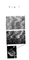
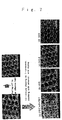
- Fig. 1 is illustrative of a porous honeycomb structure, as formed in a laboratory dish and as scaled up to two scales
- Fig. 2 is illustrative of an image thereof further scaled up by an electron microscope (SEM), and illustrates in schematic a three-dimension texture thereof.
- SEM electron microscope
- hydrophobic or biodegradable polymer employed herein, for instance, it is preferable in view of solubility in the organic solvent to use polylactic acid; lactic acid-glycolic acid copolymers; polyhydroxybutryic acid, polycaprolactone; biodegradable aliphatic polyesters such as polyethylene adipate and polybutylene adipate; aliphatic polycarbonates such as polybutylene carbonate and polyethylene carbonate; polystyrenes; polysulfones; polymethylhexadecylsiloxanes; polyvinylcarbazoles; polytetrahydrofulfuryl methacrylates; polybutyl methacrylates; polymethyl methacrylates; and polycarbonates.
- polylactic acid lactic acid-glycolic acid copolymers
- polyhydroxybutryic acid polycaprolactone
- biodegradable aliphatic polyesters such as polyethylene adipate and polybutylene adipate
- amphiphilic polymer employed herein on which no particular limitation is placed, it is preferable to use amphiphilic polymers having a polyethylene glycol-polypropylene glycol block copolymer or an acrylamide polymer as a main chain skeleton and containing a dodecyl group as a hydrophobic side chain and a lactose or carboxyl group as a hydrophilic side chain, or amphiphilic polymers having as a hydrophilic group a water-soluble protein, for instance, an ion complex of an anionic polymer such as heparin or nucleic acids, e.g., dextran sulfate DNA or RNA with a long-chain alkyl ammonium salt, gelatin, collagen, and albumin, because they are easily available.
- an anionic polymer such as heparin or nucleic acids, e.g., dextran sulfate DNA or RNA with a long-chain alkyl ammonium salt, gelatin, collagen
- the organic solvent used must be a water-insolbule one. It is also necessary that each polymer used be soluble in the organic solvent. Yet another requirement for the organic solvent is that it evaporates off readily, and causes moisture to condense readily by the latent heat of evaporation.
- organic solvent is not particularly limited insofar as it possesses such properties, it is understood that it is desired to use easily available, toxicity-free organic solvents.
- halogen-based organic solvents such as chloroform, dichloromethane and dichloroethane
- aromatic hydrocarbons such as benzene, toluene and xylene
- esters such as ethyl acetate and butyl acetate
- water-insoluble ketones such as methyl isobutyl ketone
- carbon disulfide Those organic solvents may be used alone or in the form of a mixed solvent comprising a combination of two or more.
- the combined concentration of both the hydrophobic or biodegradable polymer and the amphiphilic polymer, all soluble in the organic solvent(s), is in the range of preferably 0.01 to 20 wt%, and more preferably 0.1 to 10 wt%. Polymer concentrations of lower than 0.01 wt% are not desired because the ensuing thin film has insufficient dynamic strength. Too high polymer concentrations of more than 20 wt% fail to give any good enough honeycomb structure.
- the composition ratio of the hydrophobic or biodegradable polymer to the amphiphilic polymer should be in the range of 99:1 to 50:50 (wt/wt).
- the amphiphilic polymer ratios of less than 1 and more than 50 are not preferable because in the former case no uniform porous structure is obtainable and in the latter case the resulting porous thin film lacks stability, especially dynamic stability.
- the solution of those polymers in the organic solvent is cast on the substrate to prepare a porous thin film.
- substrate materials that are mutually dissoluble in the solution of the polymers dissolved in the organic solvent or undergo corrosion and reaction therewith or rely on chemically stable substrate materials.
- inorganic materials such as glasses, metals and silicon wafers; and polymers excellent in resistance to organic solvents, such as polypropylene, polyethylene, polyether ketone and fluororesin. While all the above substrate materials have a solid surface, it is understood that the invention is not always limited to them. In other words, it is acceptable to make use of liquids such as water, liquid paraffin and liquid polyether.
- the starting polymer solution is spread on that liquid, similar operation is carried out or, specifically, the organic solvent is evaporated in a high-humidity atmosphere to obtain a thin film having a porous honeycomb structure with droplets used as casts. Thereafter, similar peeling operation is performed to form micro-pillars.
- Use of the liquid for the substrate is rather preferable to prepare thinner films because the thickness of the polymer solution spread on the substrate can be controlled by surface tension.
- the structure can be easily removed by itself from any of the substrates while taking advantage of the feature, i.e., self-supportability, of the thin film of the porous honeycomb structure.
- a possible mechanism of forming the porous honeycomb structure could be as follows. As the hydrophobic organic solvent is evaporated, it gets rid of latent heat, lowering the temperature of the surface of the cast thin film to condense moisture, thereby aggregating and depositing micro-droplets of water on the surface of the polymer solution. The hydrophilic moiety in the polymer solution then works to decrease the surface tension between water and the hydrophobic organic solvent, so that micro-particles of water can be stabilized against coming together into an aggregate. As the solvent is further evaporated, it allows hexagonal droplets to be arranged in close-packed form and, eventually, as the water is evaporated off, it allows the polymer to be used as arranged in orderly honeycomb form.
- the environment in which the thin film is to be prepared should preferably have a relative humidity in the range of 50 to 95%.
- a relative humidity of less than 50% is not preferable because the condensation of water on the cast thin film becomes insufficient, and a relative humidity of more than 95% is again not preferable because environment control becomes difficult.
- the "porous honeycomb structure" of the invention has a double-layer texture in which two films are put one upon another (see Fig. 2) with micropores regularly arranged between them, wherein each micropore is supported by six posts that are constricted in the middle.
- a possible reason for the formation of such a complicated and orderly texture could be that atmospheric moisture is condensed by the latent heat of evaporation of the solvent on the surface of the cast polymer solution and water droplets are hexagonally close-packed, causing the polymer to be precipitated in a space except for the water droplets.
- the pore diameter and thickness of the porous thin film may be controlled by varying the concentration of the solution to be cast, the type of the solvent, the amount of the solution, the prevailing atmosphere or the flow rate, temperature and humidity of the air to be blown, i.e., controlling the evaporation speed of the solvent and the condensation speed in a suitable combination, whereby the growth of water droplets that provide the casts for pore diameter and the evaporation rate of the solvent are controllable.
- the pore diameter and thickness of the thus obtained porous thin film that is the precursor of the micro-pillar structure are in the range of 0.1 to 100 ⁇ m.
- the high-humidity air to be blown onto the film may have a relative humidity such that atmospheric moisture can be condensed on the surface of the film, i.e., a relative humidity of 20 to 100% although it varies with temperature.
- a relative humidity such that atmospheric moisture can be condensed on the surface of the film
- relatively inert gases such as nitrogen and argon may be used as well.
- the flow rate of the high-humidity air to be blown onto the film may be such that the atmospheric air is condensed on the surface of the film and the solvent used for casting is evaporated.
- the temperature of the atmosphere for blowing the high-humidity air may be such that the solvent used for casting is evaporated.
- the peeling operation for the surface of the porous thin film is typically carried out by means of peeling off an adhesive tape applied over the surface of the thin film.
- the peeling operation by the adhesive tape is capable of forming a micro-pillar structure even on a curved substrate, because a similar micro-pillar structure can be formed on either a substrate side or a tape side.
- Some other peeling operations are also usable, including ultrasonic irradiation, or dissolution of polymer. It is here noted that the micro-pillar structure formed on the substrate side can be easily peeled off as a self-supporting thin film.
- the porous-honeycomb-structure thin film provides the precursor of the micro-pillar structure, and so the spacing between the micro-pillars is in the range of about 0.1 to 100 ⁇ m depending on the pore diameter of the porous thin film.
- the height and tip size of the micro-pillar structure are in the ranges of about 0.1 to 100 ⁇ m and 0.01 to 20 ⁇ m, respectively, depending on the thickness of the porous thin film, the peeling operation applied and the material used.
- micro-pillar structure refers to a structure in which a plurality of pillars of substantially constant height are regularly arranged at a substantially constant spacing.
- Sectional shape of each pillar is not exclusively any of circular, oval, hexagonal, rectangular, square or other shapes.
- the micro-pillar structure of the invention because of having micro-pillars formed thereon, has much better properties than structures free from micro-pillars or having irregular micro-pillars, such as decreased surface resistance and much improved water repellency.
- the micro-pillar structure of the invention could have applications as a culture substrate in cell culture technology to improve the rate of deposition of cells, producing excellent actions on cell growth and differentiation, etc.
- the micro-pillar structure of the invention is quite an unheard-of material in view of not only its surface properties but also its generally unique micro-texture, and so is of great significance. The inventors make sure that novel structure could hereafter have great impacts on material designing in various fields, and give rise to far better advantages contributing much to developments in the industry.
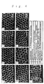
- polymethylhexadecylsiloxane were each mixed with an amphiphilic polyacrylamide (compound 1Cap: dodecylacrylamide- ⁇ -carboxyhexylacrylamide) at a weight ratio of 10:1 were cast on a glass laboratory dish of 10 cm in diameter, and the chloroform solvent was evaporated with a high-humidity air having a relative humidity of 70% blown onto the solution in a flow rate of 3 1 per minute to prepare a porous thin film having a honeycomb pattern structure in which ultramicropores all lined up regularly (Fig. 4).
- a micro-pillar structure could be prepared, in which posts lined up regularly about each micropore to support it ruptured so that ultramicro-pillars lined up regularly (Fig. 5).
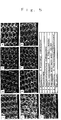
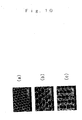
- a chloroform solution (having a polymer concentration of 4 mg/l) in which a polytetrahydrofurfuryl methacrylate having an average molecular weight of 200,000 was mixed with an amphiphilic polyacrylamide at a weight ratio of 10:1 were cast in varied amounts of 2.5, 5, 7.5 and 10 ml on a glass laboratory dish of 10 cm in diameter, and the chloroform solvent was evaporated with a high-humidity air having a relative humidity of 70% blown onto the solution in a flow rate of 2 1 per minute to prepare a porous thin film having a honeycomb pattern structure. An adhesive tape was then applied over the surface of the film, after which the tape was peeled off in a thickness direction to prepare a micro-pillar structure. SEM observations indicated that structures with micro-pillars having a varying pillar spacing could be prepared depending on the amount of the solvent cast (Fig. 6).
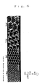
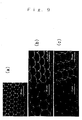
- anisotropic micro-pillar structures (Figs. 9(b) and 9(c)).
- SEM oblique observations it was found that anisotropic micro-pillar structures having quite high regularity could be obtained on both a tape side and a glass laboratory dish.
- Examples 8 to 13 are now given to show that the inventive micro-pillar structure, prepared from the hydrophobic polymer, has a water-repellent surface as compared with an ordinary film structure (hereinafter called a plain film) or a honeycomb structure with no micro-pillars, prepared from the same material.
- a plain film an ordinary film structure
- a honeycomb structure with no micro-pillars prepared from the same material.
- Example 1 was repeated using a polymethyl methacrylate having an average molecular weight of 350,000 (Aldrich) instead of the polystyrene to prepare a porous thin film having a honeycomb pattern structure, a micro-pillar structure and a plain film, and their static contact angles with water were measured. The results are set out in Table 1.
- Example 1 was repeated using a polycarbonate having an average molecular weight of 29,000 instead of the polystyrene to prepare a porous thin film having a honeycomb pattern structure, a micro-pillar structure and a plain film, and their static contact angles with water were measured. The results are set out in Table 1.
- Example 1 was repeated using a polycarbonate having an average molecular weight of 29,000 instead of the polystyrene to prepare a porous thin film having a honeycomb pattern structure, a micro-pillar structure and a plain film, and their static contact angles with water were measured. The results are set out in Table 1.
- Example 1 was repeated using a polytetrahydrofurfuryl methacrylate having an average molecular weight of 240,000 instead of the polystyrene to prepare a porous thin film having a honeycomb pattern structure, a micro-pillar structure and a plain film, and their static contact angles with water were measured. The results are set out in Table 1.
- Example 1 was repeated using a poly( ⁇ -caprolactone) having a viscosity-average molecular weight of 40,000 (made by Wako Junyaku Co., Ltd.) instead of the polystyrene to prepare a porous thin film having a honeycomb pattern structure, a micro-pillar structure and a plain film, and their static contact angles with water were measured.
- a poly( ⁇ -caprolactone) having a viscosity-average molecular weight of 40,000 made by Wako Junyaku Co., Ltd.
- Example 1 was repeated using a poly(glycolic acid-lactic acid) copolymer (available from Aldrich with a composition ratio of 50:50) having a weight-average molecular weight of 40,000 to 75,000) instead of the polystyrene to prepare a porous thin film having a honeycomb pattern structure, a micro-pillar structure and a plain film, and their static contact angles with water were measured.
- a poly(glycolic acid-lactic acid) copolymer available from Aldrich with a composition ratio of 50:50 having a weight-average molecular weight of 40,000 to 75,000
- Example 14 is now given to show that a micro-pillar structure having good wettability by water and rich hydrophilicity can be prepared by the application of hydrophilicity-imparting means to the surfaces of micro-pillars comprising polymers.
- a polylactic acid (PLLA) and Cap were mixed together at a ratio of 1:1 to prepare 2.0 g/l of a chloroform solution. This solution was cast on a laboratory dish of 9 cm in diameter and a high-humidity air was blown to the solution to obtain a honeycomb film. An upper surface of the thus prepared film was peeled off with the use of an adhesive tape to prepare a pillar (protuberance) structure.
- the contact angle in 30 seconds after dropwise addition of water droplets thereto was 39° ⁇ 10° for a plain film sample, 19° ⁇ 6° for a honeycomb sample, and 31° ⁇ 10° for a pillar structure sample, indicating that the samples were made hydrophilic.
- a polystyrene (having a molecular weight of 280,000, Aldrich) and Cap were mixed together at a ratio of 10:1 to prepare 5.0 g/l of a solution.
- This solution (7.5 ml) was cast on a laboratory dish of about 9 cm in diameter, and a high-humidity air was blown to the solution to prepare a film.
- Some upper surface of the film was peeled off with the use of an adhesive tape to prepare a pillar structure.
- Each of the obtained films was measured in terms of contact angle. At this time, the contact angles of the honeycomb and pillar structure films were 114° ⁇ 2° and 158° ⁇ 5° , respectively.
- the prepared film was treated by an ozone cleaner (NL-UV253 made by Nippon Laser Electronics Co., Ltd.), during which the contact angle on the film was measured every 30-minute ozone treatment.
- an ozone cleaner NL-UV253 made by Nippon Laser Electronics Co., Ltd.
- the contact angle was found to decrease slowly.
- the decrease in the contact angle of the honeycomb film was gentle; it kept a contact angle of about 70° even after a 180-minute treatment, whereas the pillar structure was more considerable than the honeycomb structure in terms of the decrease in the contact angle; the contact angle after the 180-minute treatment was about 30° . This would indicate that the effect of the surface shape is more enhanced by the ozone treatment.
- a honeycomb film prepared from a poly(glycolic acid-lactic acid) copolymer having a weight-average molecular weight of 40,000 to 75,000 (Aldrich) was sectioned off by peeling in a thickness direction with the use of a tape to prepare a pillar structure.
- the surfaces of the pillars were immersed in a 1N aqueous solution of sodium hydroxide for 120 minutes, followed by washing with distilled water. After drying, the static contact angle with water droplets was measured after the lapse of 30 seconds, and 120 seconds from the dropwise addition of water droplets. As a result, the film was found to have a contact angle of 164° ⁇ 2° before the immersion, but the contact angle of the film after the immersion (30 seconds and 120 seconds) was 21° ⁇ 5° and about 0° , respectively.
- the surface of the pillar structure prepared in Example 16 was immersed in a 0.2 w/v% methanol solution of a poly(2-methoxyethyl acrylate) that was a water-insoluble, hydrophilic polymer and had a weight-average molecular weight of 85,000.
- the static contact angle with water droplets was measured after the lapse of 30 seconds, and 120 seconds from the dropwise addition of water droplets.
- the film was found to have a contact angle of 164° ⁇ 2° before the coating, but the contact angle of the film after the coating (30 seconds and 120 seconds) was 29° ⁇ 4° and about 0° , respectively.
- honeycomb and pillar structures can be made hydrophilic by surface chemical modification, and ozone oxidization. Such films are expected to have possible applications to matrix materials, separation films or the like.
- a dilute polymer solution is cast on a solid substrate using water vapor as casts to obtain a thin film having a fine regular pattern of honeycomb structure and the thins film is bisected by peeling in a thickness direction, there can be provided quite an unheard-of material wherein micro-pillars are regularly lined up and formed on the peeled sections of the thin film.
- micro-pillars makes it possible to provide a surface well fit for a biochip surface that controls material flows in a constant direction, a low-friction-coefficient surface that reduces the resistance of air or water in a constant direction alone or the like.
- anisotropy is imparted to micro-pillars to add further enhancements to their own advantages, could find wide applications in various fields and make a great deal of contribution to developments in the industry.
Applications Claiming Priority (5)
| Application Number | Priority Date | Filing Date | Title |
|---|---|---|---|
| JP2002344513 | 2002-11-27 | ||
| JP2002344513 | 2002-11-27 | ||
| JP2003356881 | 2003-10-16 | ||
| JP2003356881 | 2003-10-16 | ||
| PCT/JP2003/015171 WO2004048064A1 (ja) | 2002-11-27 | 2003-11-27 | 微細突起構造体及びその製造方法 |
Publications (2)
| Publication Number | Publication Date |
|---|---|
| EP1582329A1 true EP1582329A1 (de) | 2005-10-05 |
| EP1582329A4 EP1582329A4 (de) | 2006-12-20 |
Family
ID=32396279
Family Applications (1)
| Application Number | Title | Priority Date | Filing Date |
|---|---|---|---|
| EP03775925A Withdrawn EP1582329A4 (de) | 2002-11-27 | 2003-11-27 | Mikrovorsprungsstruktur und deren herstellungsverfahren |
Country Status (4)
| Country | Link |
|---|---|
| US (1) | US7799378B2 (de) |
| EP (1) | EP1582329A4 (de) |
| JP (1) | JP4390708B2 (de) |
| WO (1) | WO2004048064A1 (de) |
Cited By (2)
| Publication number | Priority date | Publication date | Assignee | Title |
|---|---|---|---|---|
| FR2894157A1 (fr) * | 2005-12-06 | 2007-06-08 | Commissariat Energie Atomique | Membrane permeable repoussant un ou plusieurs liquides |
| EP1967342A1 (de) | 2007-03-08 | 2008-09-10 | Ricoh Company, Ltd. | Anzeigetafel, Herstellungsverfahren für eine Anzeigetafel und Anzeigeeinheit |
Families Citing this family (34)
| Publication number | Priority date | Publication date | Assignee | Title |
|---|---|---|---|---|
| US20040191127A1 (en) * | 2003-03-31 | 2004-09-30 | Avinoam Kornblit | Method and apparatus for controlling the movement of a liquid on a nanostructured or microstructured surface |
| JP4863714B2 (ja) * | 2003-08-07 | 2012-01-25 | 旭化成クラレメディカル株式会社 | 複合多孔膜とその製造方法 |
| JP4512918B2 (ja) * | 2004-03-22 | 2010-07-28 | 独立行政法人科学技術振興機構 | マイクロリングあるいはマイクロドットを呈した微細パターンの製造方法 |
| WO2007032493A1 (ja) * | 2005-09-16 | 2007-03-22 | The Furukawa Electric Co., Ltd. | 多層構造体、及び多層構造体の製造方法 |
| US9096826B2 (en) | 2005-11-22 | 2015-08-04 | Covalent Materials Corporation | Culture substrate and culture method for undifferentiated cell and undifferentiated cultured cell |
| JP4451410B2 (ja) * | 2006-03-27 | 2010-04-14 | 富士フイルム株式会社 | 多孔質フィルム及びその製造方法 |
| JP2007291185A (ja) * | 2006-04-21 | 2007-11-08 | Hokkaido Univ | ハニカム状多孔質体及びその製造方法。 |
| US9427908B2 (en) * | 2006-10-25 | 2016-08-30 | Agency For Science, Technology And Research | Modification of surface wetting properties of a substrate |
| JP4936937B2 (ja) * | 2006-11-21 | 2012-05-23 | コバレントマテリアル株式会社 | マウスes細胞培養用未分化細胞培養担体 |
| US9428728B2 (en) | 2006-11-21 | 2016-08-30 | Coorstek Kk | Carrier for undifferentiated cell culture and subculture method thereof |
| JP5344799B2 (ja) * | 2007-03-20 | 2013-11-20 | 三井化学株式会社 | 表面多孔構造体およびその製造方法 |
| JP2008248181A (ja) * | 2007-03-30 | 2008-10-16 | Fujifilm Corp | 親水性グラフトポリマーを有する多孔質フィルム及びその使用方法並びにその製造方法 |
| JP5078073B2 (ja) * | 2007-05-31 | 2012-11-21 | 三井化学株式会社 | 3次元構造が形成された樹脂フィルムの製造方法 |
| JP4910193B2 (ja) * | 2007-06-01 | 2012-04-04 | 三井化学株式会社 | 周期的な構造が形成された樹脂フィルムの製造方法 |
| CN102105578A (zh) * | 2008-05-30 | 2011-06-22 | 康宁股份有限公司 | 具有可变表面形状的细胞培养装置 |
| JP2012509663A (ja) * | 2008-11-21 | 2012-04-26 | コーニング インコーポレイテッド | 細胞培養のための、突起間隔を開けた基板および装置 |
| WO2010096072A1 (en) | 2009-02-17 | 2010-08-26 | The Board Of Trustees Of The University Of Illinois | Methods for fabricating microstructures |
| JP5417887B2 (ja) | 2009-02-24 | 2014-02-19 | 日立金属株式会社 | 絶縁電線及びその製造方法 |
| JP5537857B2 (ja) * | 2009-07-30 | 2014-07-02 | 富士フイルム株式会社 | 多孔フィルムの製造方法 |
| KR101272120B1 (ko) * | 2009-09-08 | 2013-06-10 | 에스케이이노베이션 주식회사 | 표면 몰폴로지가 조절된 광학필름 및 그 제조방법 |
| US8481303B2 (en) | 2009-10-12 | 2013-07-09 | Corning Incorporated | Microfluidic device for cell culture |
| JP2011162685A (ja) * | 2010-02-10 | 2011-08-25 | Hitachi Cable Ltd | 紫外線架橋発泡絶縁電線の製造方法 |
| JP2012077147A (ja) * | 2010-09-30 | 2012-04-19 | Lintec Corp | 撥水シート |
| JP2012170792A (ja) * | 2011-02-24 | 2012-09-10 | Kawasumi Lab Inc | 気管カニューレ |
| FR2980208B1 (fr) * | 2011-09-19 | 2018-03-16 | Institut Curie | Dispositif de guidage de la migration cellulaire et methode de guidage mettant en oeuvre un tel dispositif |
| JP2015164406A (ja) * | 2014-03-03 | 2015-09-17 | 大日本印刷株式会社 | ライフサイエンス用容器 |
| JP6218716B2 (ja) * | 2014-09-30 | 2017-10-25 | 富士フイルム株式会社 | 多孔フィルム及びその製造方法 |
| JP6386940B2 (ja) | 2015-03-02 | 2018-09-05 | 富士フイルム株式会社 | 潤滑剤保持基材及びその製造方法、滑性材料及びその製造方法 |
| JP6280065B2 (ja) * | 2015-03-02 | 2018-02-14 | 富士フイルム株式会社 | 突起構造体の製造方法 |
| WO2016194706A1 (ja) * | 2015-05-29 | 2016-12-08 | 日本バルカー工業株式会社 | 機能性複合膜の製造方法 |
| EP3398675A1 (de) * | 2017-05-02 | 2018-11-07 | Helmholtz-Zentrum Geesthacht Zentrum für Material- und Küstenforschung GmbH | Makroporöse oder mesoporöse polymerfilme in hohlfaser- oder flachfolien-geometrie |
| WO2019077604A1 (en) * | 2017-10-16 | 2019-04-25 | Solarpaint Ltd. | FLEXIBLE MICRO-PATTERN FILM SYSTEM AND METHOD FOR MANUFACTURING THE SAME |
| US11978815B2 (en) | 2018-12-27 | 2024-05-07 | Solarpaint Ltd. | Flexible photovoltaic cell, and methods and systems of producing it |
| CN114656682A (zh) * | 2020-12-23 | 2022-06-24 | 中国科学院宁波材料技术与工程研究所 | 一种超疏水化聚乳酸多孔材料的制备方法 |
Citations (6)
| Publication number | Priority date | Publication date | Assignee | Title |
|---|---|---|---|---|
| US3354022A (en) * | 1964-03-31 | 1967-11-21 | Du Pont | Water-repellant surface |
| WO2000020210A1 (en) * | 1998-10-05 | 2000-04-13 | 3M Innovative Properties Company | Slip control article for wet and dry applications |
| WO2000050232A1 (fr) * | 1999-02-25 | 2000-08-31 | Seiko Epson Corporation | Element structure presentant d'excellentes proprietes hydrofuges et son procede de fabrication |
| EP0760840B1 (de) * | 1994-05-24 | 2001-02-14 | Minnesota Mining And Manufacturing Company | Wiederverwendbarer artikel mit einer mikrostrukturierten oberfläche, kits zu ihrer herstellung und verfahren zu ihrer verwendung |
| WO2004000568A1 (en) * | 2002-06-25 | 2003-12-31 | 3M Innovative Properties Company | Film with microstructured surface |
| EP1214469B1 (de) * | 1999-09-21 | 2004-01-02 | Asten Privatgesellschaft mit beschränkter Haftung | Bespannung einer papiermaschine |
Family Cites Families (12)
| Publication number | Priority date | Publication date | Assignee | Title |
|---|---|---|---|---|
| JPH09155972A (ja) * | 1995-12-12 | 1997-06-17 | Ykk Corp | 撥水性フィルムとその製造方法 |
| JPH09239829A (ja) | 1996-03-13 | 1997-09-16 | Toray Ind Inc | 二軸配向ポリエステルフィルム |
| JP3853881B2 (ja) | 1996-10-07 | 2006-12-06 | 明義 尾坂 | 医用インプラント材の表面処理方法及び生体親和性インプラント |
| US6291050B1 (en) * | 1998-10-30 | 2001-09-18 | The Procter & Gamble Company | Topsheet systems for absorbent articles exhibiting improved hydrophilicity gradients |
| JP2000217625A (ja) * | 1999-02-01 | 2000-08-08 | Ohiro Seisakusho:Kk | 洗髪用防水シート,及びそれを用いた自動洗髪機 |
| JP4431233B2 (ja) | 1999-11-30 | 2010-03-10 | テルモ株式会社 | ハニカム構造体およびその調製方法、ならびにその構造体を用いたフィルムおよび細胞培養基材 |
| DE10062203A1 (de) | 2000-12-13 | 2002-06-20 | Creavis Tech & Innovation Gmbh | Verfahren zur Abformung von hydrophoben Polymeren zur Erzeugung von Oberflächen mit beständig wasser- und ölabweisenden Eigenschaften |
| JP2002335949A (ja) | 2001-05-22 | 2002-11-26 | Inst Of Physical & Chemical Res | ハニカム構造体フィルムを用いた細胞の三次元組織培養法 |
| JP4731044B2 (ja) * | 2001-05-22 | 2011-07-20 | 独立行政法人理化学研究所 | 延伸フィルムおよびそれを用いた細胞培養基材 |
| JP2003128832A (ja) * | 2001-10-23 | 2003-05-08 | Inst Of Physical & Chemical Res | 自己組織化有機薄膜を有する構造体 |
| JP4311907B2 (ja) | 2002-02-28 | 2009-08-12 | 株式会社リコー | 有機薄膜とその製造方法及びそれを利用した光記録媒体 |
| JP4056783B2 (ja) | 2002-04-12 | 2008-03-05 | 株式会社リコー | 有機薄膜の製造方法及びそれを用いた光記録媒体 |
-
2003
- 2003-11-27 US US10/536,589 patent/US7799378B2/en not_active Expired - Fee Related
- 2003-11-27 WO PCT/JP2003/015171 patent/WO2004048064A1/ja not_active Application Discontinuation
- 2003-11-27 EP EP03775925A patent/EP1582329A4/de not_active Withdrawn
- 2003-11-27 JP JP2004555064A patent/JP4390708B2/ja not_active Expired - Fee Related
Patent Citations (6)
| Publication number | Priority date | Publication date | Assignee | Title |
|---|---|---|---|---|
| US3354022A (en) * | 1964-03-31 | 1967-11-21 | Du Pont | Water-repellant surface |
| EP0760840B1 (de) * | 1994-05-24 | 2001-02-14 | Minnesota Mining And Manufacturing Company | Wiederverwendbarer artikel mit einer mikrostrukturierten oberfläche, kits zu ihrer herstellung und verfahren zu ihrer verwendung |
| WO2000020210A1 (en) * | 1998-10-05 | 2000-04-13 | 3M Innovative Properties Company | Slip control article for wet and dry applications |
| WO2000050232A1 (fr) * | 1999-02-25 | 2000-08-31 | Seiko Epson Corporation | Element structure presentant d'excellentes proprietes hydrofuges et son procede de fabrication |
| EP1214469B1 (de) * | 1999-09-21 | 2004-01-02 | Asten Privatgesellschaft mit beschränkter Haftung | Bespannung einer papiermaschine |
| WO2004000568A1 (en) * | 2002-06-25 | 2003-12-31 | 3M Innovative Properties Company | Film with microstructured surface |
Non-Patent Citations (2)
| Title |
|---|
| MORAN P M ET AL: "Microstamping of freestanding bipolymer features" APPLIED PHYSICS LETTERS, AMERICAN INSTITUTE OF PHYSICS, MELVILLE, NY, US, vol. 78, no. 23, 4 June 2001 (2001-06-04), pages 3741-3743, XP012028248 ISSN: 0003-6951 * |
| See also references of WO2004048064A1 * |
Cited By (4)
| Publication number | Priority date | Publication date | Assignee | Title |
|---|---|---|---|---|
| FR2894157A1 (fr) * | 2005-12-06 | 2007-06-08 | Commissariat Energie Atomique | Membrane permeable repoussant un ou plusieurs liquides |
| WO2007065873A1 (fr) * | 2005-12-06 | 2007-06-14 | Commissariat A L'energie Atomique | Membrane permeable repoussant un liquide |
| EP1967342A1 (de) | 2007-03-08 | 2008-09-10 | Ricoh Company, Ltd. | Anzeigetafel, Herstellungsverfahren für eine Anzeigetafel und Anzeigeeinheit |
| US8241731B2 (en) | 2007-03-08 | 2012-08-14 | Ricoh Company, Ltd. | Display panel, method of manufacturing a display panel, and display unit |
Also Published As
| Publication number | Publication date |
|---|---|
| JP4390708B2 (ja) | 2009-12-24 |
| EP1582329A4 (de) | 2006-12-20 |
| JPWO2004048064A1 (ja) | 2006-03-23 |
| WO2004048064A1 (ja) | 2004-06-10 |
| US20060097361A1 (en) | 2006-05-11 |
| US7799378B2 (en) | 2010-09-21 |
Similar Documents
| Publication | Publication Date | Title |
|---|---|---|
| US7799378B2 (en) | Process for producing micropillar structure | |
| JP4731044B2 (ja) | 延伸フィルムおよびそれを用いた細胞培養基材 | |
| Wan et al. | Multiple interfaces in self-assembled breath figures | |
| Zhou et al. | Superwetting Janus membranes: focusing on unidirectional transport behaviors and multiple applications | |
| KR102096286B1 (ko) | 고분자 초박막 및 다공질 고분자 초박막 | |
| Jani et al. | Nanoporous anodic aluminium oxide: Advances in surface engineering and emerging applications | |
| Park et al. | Hierarchically ordered polymer films by templated organization of aqueous droplets | |
| EP1815973A1 (de) | Eine durch eine wasserstoffbrückenbindung gebondete mehrlagige folie umfassendes laminat, aus dem laminat bereitgestellte selbsttragende dünne folie und herstellungsverfahren und verwendung dafür | |
| UÇAR et al. | Droplet condensation on polymer surfaces: A review | |
| Guo et al. | Research status and development trend of three-dimensional colloidal crystals | |
| CN109900642B (zh) | 一种亚微米级光学微型反应器及其制备方法 | |
| JP4247432B2 (ja) | 凹凸を有するハニカム構造体フィルム | |
| JP5050205B2 (ja) | 孔の孤立したハニカム構造体の製造方法 | |
| Jibowu | A review on nanoporous metals | |
| JP4342338B2 (ja) | 3次元多孔質構造体とその製造方法 | |
| JP5231909B2 (ja) | 任意の分布形状と分布密度を有する分子または粒子の集団を同時に多種大量生成する方法とその方法に使用するマスク材 | |
| CN110371919B (zh) | 一种微纳米多级柱结构的自组装制备方法 | |
| JP2004154769A (ja) | バイオミメティックメンブランの製造方法およびバイオミメティックメンブランならびにその応用 | |
| Xiong et al. | Honeycomb structured porous films prepared by the method of breath figure: history and development | |
| EP2106858A1 (de) | Substrat und Zielplatte | |
| Yao et al. | Femtosecond-laser-patterned origami Janus membrane toward enhanced water fog harvesting | |
| Nguyen et al. | Immobilization of bio-macromolecules onto membranes via an adsorbed nanolayer: an insight into the mechanism | |
| JP2004330330A (ja) | ハニカム構造体を鋳型としたメゾ構造体の作製 | |
| Nishikawa et al. | Honeycomb film of an amphiphilic copolymer: Fabrication and characterization | |
| Wang et al. | A Superhydrophilic Silicon Surface Enhanced by Multiscale Hierarchical Structures Fabricated by Laser Direct Writing |
Legal Events
| Date | Code | Title | Description |
|---|---|---|---|
| PUAI | Public reference made under article 153(3) epc to a published international application that has entered the european phase |
Free format text: ORIGINAL CODE: 0009012 |
|
| 17P | Request for examination filed |
Effective date: 20050527 |
|
| AK | Designated contracting states |
Kind code of ref document: A1 Designated state(s): AT BE BG CH CY CZ DE DK EE ES FI FR GB GR HU IE IT LI LU MC NL PT RO SE SI SK TR |
|
| RBV | Designated contracting states (corrected) |
Designated state(s): DE FR GB |
|
| RIC1 | Information provided on ipc code assigned before grant |
Ipc: C08J 9/00 20060101ALI20060427BHEP Ipc: C12M 3/00 20060101ALI20060427BHEP Ipc: B29C 41/36 20060101ALI20060427BHEP Ipc: B29C 41/12 20060101ALI20060427BHEP Ipc: B29C 59/02 20060101AFI20060427BHEP |
|
| A4 | Supplementary search report drawn up and despatched |
Effective date: 20061117 |
|
| 17Q | First examination report despatched |
Effective date: 20070307 |
|
| STAA | Information on the status of an ep patent application or granted ep patent |
Free format text: STATUS: THE APPLICATION IS DEEMED TO BE WITHDRAWN |
|
| 18D | Application deemed to be withdrawn |
Effective date: 20070718 |