EP1577876A1 - Electronic apparatus with display unit, information-processing method, and computer product - Google Patents
Electronic apparatus with display unit, information-processing method, and computer product Download PDFInfo
- Publication number
- EP1577876A1 EP1577876A1 EP05005866A EP05005866A EP1577876A1 EP 1577876 A1 EP1577876 A1 EP 1577876A1 EP 05005866 A EP05005866 A EP 05005866A EP 05005866 A EP05005866 A EP 05005866A EP 1577876 A1 EP1577876 A1 EP 1577876A1
- Authority
- EP
- European Patent Office
- Prior art keywords
- icon
- display
- assigned
- screen
- electronic apparatus
- Prior art date
- Legal status (The legal status is an assumption and is not a legal conclusion. Google has not performed a legal analysis and makes no representation as to the accuracy of the status listed.)
- Ceased
Links
- 230000010365 information processing Effects 0.000 title claims description 10
- 238000003672 processing method Methods 0.000 title claims description 10
- 230000008859 change Effects 0.000 claims abstract description 40
- 230000003287 optical effect Effects 0.000 claims description 13
- 238000001514 detection method Methods 0.000 claims description 4
- 230000007246 mechanism Effects 0.000 claims description 4
- 210000005252 bulbus oculi Anatomy 0.000 claims description 3
- 238000004590 computer program Methods 0.000 claims description 3
- 239000004973 liquid crystal related substance Substances 0.000 claims description 3
- 230000007423 decrease Effects 0.000 claims description 2
- 230000006870 function Effects 0.000 description 43
- 238000000034 method Methods 0.000 description 17
- 238000012545 processing Methods 0.000 description 12
- 101100115215 Caenorhabditis elegans cul-2 gene Proteins 0.000 description 8
- 240000005924 Stenocarpus sinuatus Species 0.000 description 7
- 230000003247 decreasing effect Effects 0.000 description 6
- 230000000881 depressing effect Effects 0.000 description 6
- 230000008569 process Effects 0.000 description 6
- 238000006243 chemical reaction Methods 0.000 description 3
- 238000010276 construction Methods 0.000 description 3
- 238000005070 sampling Methods 0.000 description 3
- 230000006835 compression Effects 0.000 description 2
- 238000007906 compression Methods 0.000 description 2
- 238000010586 diagram Methods 0.000 description 2
- 230000011514 reflex Effects 0.000 description 2
- GGCZERPQGJTIQP-UHFFFAOYSA-N sodium;9,10-dioxoanthracene-2-sulfonic acid Chemical compound [Na+].C1=CC=C2C(=O)C3=CC(S(=O)(=O)O)=CC=C3C(=O)C2=C1 GGCZERPQGJTIQP-UHFFFAOYSA-N 0.000 description 2
- 238000013459 approach Methods 0.000 description 1
- 238000004364 calculation method Methods 0.000 description 1
- 238000012790 confirmation Methods 0.000 description 1
- 238000012937 correction Methods 0.000 description 1
- 238000005516 engineering process Methods 0.000 description 1
- 239000000284 extract Substances 0.000 description 1
- 238000001914 filtration Methods 0.000 description 1
- 238000003384 imaging method Methods 0.000 description 1
- 238000012986 modification Methods 0.000 description 1
- 230000004048 modification Effects 0.000 description 1
- 230000008520 organization Effects 0.000 description 1
- 230000035945 sensitivity Effects 0.000 description 1
- 230000001360 synchronised effect Effects 0.000 description 1
- 230000000007 visual effect Effects 0.000 description 1
Images


Classifications
-
- H—ELECTRICITY
- H04—ELECTRIC COMMUNICATION TECHNIQUE
- H04N—PICTORIAL COMMUNICATION, e.g. TELEVISION
- H04N23/00—Cameras or camera modules comprising electronic image sensors; Control thereof
- H04N23/60—Control of cameras or camera modules
- H04N23/63—Control of cameras or camera modules by using electronic viewfinders
- H04N23/631—Graphical user interfaces [GUI] specially adapted for controlling image capture or setting capture parameters
- H04N23/632—Graphical user interfaces [GUI] specially adapted for controlling image capture or setting capture parameters for displaying or modifying preview images prior to image capturing, e.g. variety of image resolutions or capturing parameters
-
- H—ELECTRICITY
- H04—ELECTRIC COMMUNICATION TECHNIQUE
- H04N—PICTORIAL COMMUNICATION, e.g. TELEVISION
- H04N23/00—Cameras or camera modules comprising electronic image sensors; Control thereof
- H04N23/60—Control of cameras or camera modules
- H04N23/63—Control of cameras or camera modules by using electronic viewfinders
- H04N23/633—Control of cameras or camera modules by using electronic viewfinders for displaying additional information relating to control or operation of the camera
- H04N23/634—Warning indications
Definitions
- the present invention relates to an electronic apparatus with a display unit, an Information-processing method, and a computer product.
- OSD on-screen display
- Icons that indicate device states and operating conditions, characters, or the like are displayed in superimposition on a main image on a display screen. Based on these icons and the like that Indicate a set operation mode of the device and give guidance to a device user, the user can interact with the device.
- Japanese Patent Application Laid-Open No. H11-146234 discloses a conventional example of a device having the OSD function.
- the invention described in this publication relates to a digital camera.
- the digital camera has a mode of reproducing and displaying image data stored in a memory card, and a mode of displaying a photographed image through the digital camera.
- Image data and character data showing a counter, a date, a photographing condition, and the like are combined, and the combined data are displayed on a screen of a liquid crystal display device (LCD) as a display unit.
- LCD liquid crystal display device
- the invention disclosed in this publication has an object of securing a normal display by avoiding a difference of sizes between character data displayed on the screen attributable to different scan speeds between the display modes.
- An electronic apparatus with a display unit which can display icons indicating an apparatus state or an operating condition based on an on-screen display function, includes an apparatus-condition detecting unit that detects a change of the apparatus state or a change of a setting of the operating condition; an icon assigning unit that assigns an icon indicating the apparatus state or the operating condition for which the change is detected by the apparatus-condition detecting unit; and an on-screen-display controller that displays the icon assigned in a shape different from the icon before being assigned.
- An information-processing method which is for controlling an electronic apparatus with a display unit that can display Icons indicating an apparatus state or an operating condition based on an on-screen display function, Includes determining a change of the apparatus state or a change of a setting of the operating condition; assigning an icon indicating the apparatus state or the operating condition for which the change is detected at the determining; and displaying the icon assigned in a shape different from the Icon before being assigned based on the on-screen display function.
- a computer-readable recording medium stores a computer program that makes a computer execute the above information-processing method according to the present invention.
- a digital camera is explained as the electronic apparatus.
- the present invention can be also applied to an electronic apparatus other than the digital camera having a compact display as a user interface in which a set operating mode and the like can be determined according to an icon display using an OSD function.
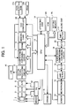
- Fig. 1 is a block diagram of a basic configuration of the digital camera according to the present embodiment.
- the digital camera shown in Fig. 1 includes a lens 1, a mechanism 2 including an automatic focusing mechanism, a charge-coupled device (CCD) 3, a correlation double sampling (CDS) circuit 4, an analog/digital (A/D) converter 5, a digital signal processing circuit 6, a compressing/expanding circuit 7, a dynamic random access memory (DRAM) 8, a memory card 9, an LCD 10, a driver 11, a synchronous generator (SG) 12, a central processing unit (CPU) 13, an operating unit 14, a strobe light 15, a microphone 16, an amplifier/ filter (AMP/FILTER) 17, a digital/analog (D/A) converter 18, an audio data compressing/expanding circuit 19, an analog/digital (A/D) converter 20, an (AMP/FILTER) 21, and an on-screen-display controller 22.
- a lens 1 includes a lens 1, a mechanism 2 including an automatic focusing mechanism,
- a lens unit Includes the lens 1, the mechanism 2 having an automatic focusing (AF) unit, a diaphragm, and a filtering unit.
- the CCD 3 converts an image input via the lens unit into an electric signal (analog Image data).
- the CDS circuit 4 decreases noise of a CCD imaging device.
- the A/D converter 5 converts the analog image data input from the CCD 3 via the CDS circuit 4 into digital image data. In other words, a signal output from the CCD 3 passes through the CDS circuit 4, and the A/D converter 5 converts this signal into a digital signal at an optimum sampling frequency.
- the digital signal processor 6 divides the image data input from the A/D converter 5 into color difference data and luminance data, and processes the data to correct and compress/expand the image.
- the image compressing/expanding circuit 7 carries out an orthogonal conversion/inverse orthogonal conversion as one process of the image compression/expansion based on the JPEG (Joint Photographic Experts Group), and a Huffman coding/Huffman decoding as a process of the image compression/expansion based on the JPEG.
- JPEG Joint Photographic Experts Group
- a sound/electric signal converting device like a microphone 16 converts sound into an electric signal, and this signal becomes audio data.
- the AMP/FILTER 17 amplifies this audio data, and cuts off the amplified audio data into a necessary band,
- the D/A converter 18 converts the audio data into digital audio data at a sampling frequency of two or more times of a predetermined band.
- the data compressing/expanding unit 19 compresses and encodes the digital audio data.
- the DRAM 8 temporarily stores the compressed Image data.
- the compressed image data is stored as an image data file and the compressed audio data is recorded as an audio data file, in the memory card 9.
- the LCD 10 directly displays the image data photographed by the CCD 3, and displays an image corresponding to the image data recorded in the memory card 9.
- the LCD 10 also displays a set state of the digital still camera, such as a set mode, and an error, using the OSD function described in detail later.
- the CPU 13 controls the operation of each unit of the digital still camera following a control program stored in the ROM 23, according to an instruction from the operating unit 14 or an external operation instruction based on a remote control or the like (not shown). Specifically, the CPU 13 issues a control command concerning the control of the recording of the image data and the control of the reproduction of the image data. The CPU 13 also issues a control command concerning the control of the display of icons in the on-screen-display controller 22, following the OSD control program stored in the ROM 23,
- the operating unit 14 has operation buttons and the like to externally carry out a selection of a function, a photographing instruction, and various other settings.
- the on-screen-display controller 22 generates icon data, and outputs the generated icon data to the digital signal processing circuit 6 at timing of a dot clock in a predetermined cycle,
- the icon data includes character display data of a counter, a time, and a date, symbol data such as a photographing condition, and the like.
- the digital camera has a reproduction mode of displaying in the LCD 10 image data which is photographed by the CCD 3 and is temporarily stored in the memory card 9, and a through image mode of directly displaying in the LDC 10 image data which is photographed by the CCD 3.
- the CCD 3 converts an image picked up through the lens 1 into an electric signal (analog image data).
- the analog image data passes through the CDS 4, and is input to the A/D converter 5.
- the A/D converter 5 converts the analog image data into digital image data.
- the digital signal processing circuit 6 signal-processes the converted digital image data, and the processed image data is stored in the DRAM 8 via a CPU bus.
- the digital image data stored in the DRAM 8 is input to the compressing/expanding circuit 7 via the CPU bus, is compressed, and the compressed data is stored in the DRAM 8 again.
- the CPU 13 records the compressed image data stored in the DRAM 8 as an image data file in a predetermined format, into the memory card 9, via the CPU bus.
- the Image data stored in the memory card 9 is reproduced as follows.
- the operating unit 14 When a user operates the operating unit 14 to assign an image data file stored in the memory card 9 to reproduce this image data, the compressed image data in the assigned image data file is read out, and is stored in the DRAM 8.
- the image data stored in the DRAM 8 is input to the compressing/expanding circuit 7 via the CPU bus, and is expanded.
- the expanded image data is stored in the DRAM 8 again.
- the expanded image data stored in the DRAM 8 is input to the digital signal processing circuit 6 via the CPU bus, and is converted into a video signal to be displayed in the LCD 10.
- the CCD 3 converts the Image picked up through the lens 1 into an electric signal (analog image data).
- the analog image data passes through the CDS 4, and is input to the A/D converter 5.
- the A/D converter 5 converts the analog image data into digital image data.
- the digital signal processing circuit 6 signal-processes the converted digital image data, and the processed Image data is once stored in the DRAM 8.
- the image data is converted into a video signal to be displayed in the LCD 10.
- the on-screen-display controller 22 includes a command decoder that decodes a command input from the CPU 13, a video RAM (VRAM) 22b in which icon data read from an Icon data generator read-only memory (ROM) 22a is extracted, the icon data generator ROM 22a that outputs icon data corresponding to a command sent out from the CPU 13, an oscillating circuit that outputs a dot clock to an output controller, and an output controller that outputs icon data extracted in the video RAM 22b to the digital signal processing circuit 6 at timing of the dot clock Input from the oscillating circuit, by synchronizing the icon data with a vertical synchronization signal and a horizontal synchronization signal.
- VRAM video RAM
- ROM Icon data generator read-only memory
- the on-screen-display controller 22 receives reference result information from the CPU 13 after the CPU 13 refers to a setting memory 23 held by the CPU 13, and the on-screen-display controller 22 selects an item of which setting is changed.
- the on-screen-display controller 22 inputs command data from the CPU 13.
- the on-screen-display controller 22 reads icon data indicated by a decoded command, from the icon data generator ROM 22a, and extracts the icon data in the video RAM 22b.
- the output controller outputs the extracted icon data to the digital signal processing circuit 6 at timing of the dot clock input from the oscillating circuit, by synchronizing the icon data with the vertical synchronization signal and the horizontal synchronization signal.
- the digital signal processing circuit 6 combines a through image to be reproduced or a reproduced image, with icon data input from the on-screen-display controller 22.
- the digital signal processing circuit 6 carries out a signal conversion of the combined data so that it can be displayed, and displays the combined image on the screen of the LCD 10,
- the sensor 24 is an infrared sensor, for example.
- the infrared sensor detects the approach of the operator.
- a detected signal is sent to the CPU 13 to make a setting so that the on-screen-display controller 22 can execute the OSD control function.
- the following sensors can be also used, in addition to the infrared sensor, a distance sensor that measures a distance between the camera and a human body, a contact sensor that detects a contact of a human body on the camera, an optical sensor that detects using light, an eyeball detection sensor that detects an eyeball, an eyeshot detection sensor that detects an eyeshot of a person, and a pressure sensor that detects a pressure when a person holds the digital camera.
- the sensor 24 automatically detects that the operator is at a near position, and the CPU 13 starts the OSD control function using the OSD control program.
- the LCD 10 is a monitor that is generally disposed at the back of the digital camera, and is used to display an image to be photographed or display a photographed image.
- the LCD 10 is not limited to the monitor that is generally disposed at the back of the digital camera, but can be an electronic view finder (EVF).
- EMF electronic view finder
- the LCD 10 can be also disposed within the optical finder to make a display. While the LCD is applied to the digital camera according to the present embodiment, the LCD can be also used for an icon display unit of the optical finder within a general silver salt film camera.
- the OSD function used as the user interface in the digital camera having the above configuration is further explained.
- an operation mode set by a user can be determined based on the display of icons using the OSD function.
- the operating condition is set in an automatic mode of automatically setting a photographing condition or is determined by default.
- the setting of the automatic mode determined in advance in the device is changed by a user operation, the user can determine whether the changed setting is correct.
- the digital camera can carry out a proper photographing in the automatic mode or in the default setting.
- the setting is to be changed, this means that the user intentionally changes the setting. Since the change of the setting has a risk of failure in photographing, the user needs to determine whether the changed setting is correct.
- Fig. 2 is a schematic of icons enlarged on the LCD 10 based on an OSD function of the digital camera according to the present embodiment.
- a screen 30a shows a normal display where the icons are not a hindrance
- a screen 30b shows the icons that are displayed in an enlarged size immediately before photographing an image.
- the display of the icons using the OSD function that enables the user to determine about the user setting is carried out simultaneously with the user setting.
- the icons are displayed at the edge of the screen by taking into account a size and a position that do not hinder the photographing image (a background image) of the camera that becomes a base of the display screen.
- the size of the icons shown on the screen 30a shown in Fig. 2 is increased to about two to four times to obtain icons 31L, 32L, and 33L to be superimposed on a major part of the background image (the image to be photographed by the camera).
- the user can sufficiently confirm the setting contents, thereby solving the above problem, and improving visibility.
- the CPU 13 Based on the input operation of the operating unit 14, the CPU 13 stores the setting of the photographing (operation) conditions changed by the user operation into the setting memory 25 that stores the control data.
- the setting memory 25 holds the changed setting until when the power source is turned off or until when the setting is further changed at the next input operation. Therefore, in carrying out an enlarged display of the icons, the CPU 13 checks the setting memory 25 to determine whether there is a user setting. When the CPU 13 determines that data is present in the setting memory 25, the CPU 13 specifies the icons to be displayed in a large size based on the setting contents, and transmits a command to the on-screen-display controller 22 to control the display.
- the on-screen-display controller 22 Upon receiving this command, the on-screen-display controller 22 takes out the icon data to be used for the indicated enlarged display, from the ROM, and outputs the Icon data to the digital signal processing circuit 6, Required data for enlarged display can be prepared from the icon data used for a normal display based on calculation.
- the enlarged display of the icons is useful to confirm whether the setting operation is correct. This setting is maintained until the power source is turned off as described above. Therefore, it is necessary to confirm the setting each time of photographing an image even when the setting is not carried out.
- the enlarged icons are superimposed on a major part of the image to be photographed by the camera as the base of the display screen, as shown on the screen 30b shown in Fig. 2. Therefore, when icons that completely hide the photographed image are used, it is desirable to use the control of ending the enlarged display of the icons after making a determination based on the enlarged icons, thereby returning the display of the icons to the normal display state as shown on a screen 35b from the state of the enlarged display shown on a screen 35a shown in Fig. 4.
- a first method of controlling the starting or the ending of the state of the enlarged display of the icons is based on an instruction by the user operation, For example, the user starts the enlarged display of the icons by half depressing a release button, and then returns the button from the half-depressed state to the original state, or depresses another hard key, thereby ending the enlarged display of the icons.
- a second method of controlling the starting or the ending of the state of the enlarged display of the icons is as follows.
- the operator depresses the release (shutter) button.
- the CPU 13 determines that the photographing is ready, and starts the enlarged display of the icons. After a lapse of a predetermined time, the device automatically ends the enlarged display.
- the first and the second methods can be used in combination.
- either the starting or the ending of the enlarged display is carried out automatically or is carried out by the user operation.
- the automatic control and the user operation can be used in combination.
- the enlarged icons are superimposed on a major part of the image to be photographed by the camera as the base of the display screen, as shown on the screen 30b shown in Fig. 2. Therefore, when the icons completely hide the image to be photographed, it is inconvenient for the user to determine an image construction of the object.
- the enlarged icons are displayed as a semitransparent image
- the user can also employ a system in which the user can select a semitransparent or an opaque display.
- the icons are used for the operation at the display time or for the user setting carried out in advance.
- the method of displaying the enlarged icons as a semitransparent image is effective because the image to be photographed is visible through the semitransparent image when the user cannot end the enlarged display of the icons, that is, when the device automatically ends the enlarged display.
- the semitransparent image can be superimposed on the base image on the display screen based on a known method.
- the photographing operation by the camera can be independent of the operation of enlarging the icons. Based on the same concept as the semitransparent display of the enlarged icons, it is necessary to avoid restricting the photographing operation as much as possible while allowing the photographing operation with a display of enlarged icons. Therefore, while the icons are displayed in a large size, the camera is set to a photographable state. In other words, while the icons are displayed in a large size, the user can photograph the image when the user depresses the release (shutter) button. By carrying out the control following these conditions, the user can perform a proper photographing without missing a shutter chance.
- the enlarged display of the icons can be started when the power source of the digital camera is turned on.
- the user can visually confirm a change of the setting simultaneously with the turning on of the power source for photographing.
- the icons corresponding to the changed setting can be displayed after a lapse of a certain time since the user turns on the power source of the digital camera. This is suitable because, in many cases, the user does not start the photographing operation immediately after the power source is turned on.
- the icons corresponding to the changed setting can be displayed after a lapse of a first predetermined time since the user turns on the power source of the digital camera, and the icons can be returned to a normal mode after a lapse of a second predetermined time.
- the power source Is turned on the user visually confirms the changed setting after a lapse of a certain time. After ending the visual confirmation in a certain time, the user carries out the normal photographing. Therefore, it is very convenient when the enlarged display of the icons is returned to the normal display by the time when the photographing operation is carried out.
- the enlarged icons can be displayed at timing when the object is in focus in a half-depressed state of the shutter button.
- the enlarged icons are displayed at the timing when the object is in focus In a half-depressed state of the shutter button of the digital camera, the user is not hindered by the enlarged display from looking at the object screen until immediately before the user starts half depressing the shutter button.
- the enlarged icons are displayed when the user starts half depressing the shutter button. Therefore, the user can secure visibility of confirming the object, and visibility of confirming the icons corresponding to the changed setting.
- the operating unit 14 can have an input button which the operator can depress. When the operator depresses the input button, the operating unit 14 transmits an input signal to the on-screen-display controller 22. Upon reception of the input signal, the on-screen-display controller 22 can control starting, ending, and suspending the enlarged display of the Icons. This arrangement can improve the degree of freedom of the operator.
- Fig. 3 is a flowchart of a process procedure for an icon display control according to the present embodiment. The operation of the icon display control executed by the CPU 13 is explained with reference to the flowchart shown in Fig. 3. First, the CPU 13 determines whether a setting condition is complete and photographing conditions are ready (step S101).
- step S101 the CPU 13 determines whether the user has changed a setting condition (step S102). This processing is obtained as a result of checking a memory area for storing the user setting, When there is a changed setting of condition, the changed setting condition is stored in the memory area.
- the CPU 13 specifies the changed setting condition, assigns icons corresponding to the specified setting condition as icons to be displayed in a large size, and transmits an on-screen display command to the on-screen-display controller 22, thereby starting the enlarged display of the target icons (step S103),
- the enlarged display of the icons is carried out for a predetermined time. In order to carry out this time control, a timer is turned on to count the predetermined time.
- the CPU 13 determines whether the user has confirmed the setting (step S104).
- the on-screen-display controller ends the enlarged display of the icons (step S106).
- the timer that counts the predetermined time is set off, and the operation ends.
- step S104 determines whether the predetermined time of displaying the enlarged icons has passed based on the timer which is turned on in advance (step S105). When the predetermined time has not passed, the process returns to step S104 of determining whether the user has confirmed the setting.
- the on-screen-display controller ends the enlarged display of the icons (step S106).
- the timer that counts the predetermined time is set off, and the operation ends.
- Fig. 4 is a schematic for illustrating the LCD 10 in which the display changes to a normal display after the icons are enlarged based on the OSD function of the digital camera, according to the present embodiment.
- the enlarged display can simply end In the manner as shown by the screen 35a changing to the screen 35b show in Fig. 4.
- the user can confirm, at a high recognition rate, the setting condition that is changed by the user operation.
- the size of the enlarged target icons is gradually decreased, and the icons are shifted to predetermined positions when the size of the icons is returned to the normal display size.
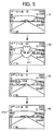
- Fig. 5 is a schematic for illustrating a change in the display of an enlarged icon on the screen.
- an example of an icon of a "tulip flower” is displayed in an enlarged size, when the user sets a close-up mode function in photographing by depressing a "close-up mode” button schematically indicated by a tulip flower in a photographing mode (not shown).
- a screen 41 shown in Fig. 5 shows a state of the screen before the user carries out the setting operation.
- a screen 42 shows a state that a "tulip flower” icon 41 L is displayed in the enlarged size after the user sets the close-up mode.
- the size of the enlarged display of the "tulip flower” icon 41L shown on the screen 42 shown in Fig. 5 is decreased in size to that of a "tulip flower” icon 41 M shown on a screen 43 shown in Fig. 5.
- the tulip flower icon is displayed in the normal small size as shown by a "tulip flower” Icon 41 S at a predetermined position on a screen 44 shown in Fig. 5.
- the display size of the icon is gradually decreased as shown on the screen 42 to the screen 44. Based on this display method, the user can recognize, at an improved recognition rate, the setting of the operation mode (function) and the like indicated by the enlarged display of the icon in relation to the layout of the object. Further, a setting error in the photographing condition by the user can be decreased,
- the digital camera has a function of making an enlarged display of icons that indicate the operation mode (function) and the like changed by the user setting.
- the user sets the utilization of this function in advance, and uses this setting, is explained.
- the user can select whether to carry out an enlarged display of icons, and can select an operation mode (function) and the like indicated by the icons when the enlarged display of the icons is selected.
- Fig. 6 is a schematic for illustrating a user setting screen 61 when the user uses an Icon enlarged-display function, and a display screen 62 following this setting, according to the present embodiment.
- the user can instruct the setting of each item by inputting ON or OFF to each item.
- the user Inputs OFF to the item "enlarged display of icons corresponding to a changed setting"
- the user inputs ON to this item.
- the user inputs ON to each of "macro”, "photographing mode", and "AF/MF/SNAP/distant view”. Therefore, four icons on the screen 61 shown in Fig. 6, i.e., a mountain icon (distant view) 32L, a serial shot icon (a photographing mode) 33L, a flash prohibition icon (a photographing mode) 31 L, and a flower icon (macro) 34L, indicate that these icons can be displayed in a large size. In this way, the camera operates to meet user's requests.
- the icons are displayed on the LCD 10 in the above explanation, the icons can be also displayed on an electronic view finder (EVF).
- EVF electronic view finder
- Fig. 7 is a schematic for illustrating a display within an optical finder when the OSD function according to the present invention is applied to the optical finder of a single-lens reflex camera. Icons are displayed in the display unit disposed within the optical finder, in place of the LCD 10. In a frame 70 displayed within the optical finder, icons of a flash 71, a close-up mode 72, and ISO (International Standardization Organization) sensitivity 73 are displayed. When the operator sets these icons, the icons are lighted to emphasize the setting change.
- ISO International Standardization Organization
- the icon display unit 70 of the optical finder can be applied to not only a digital camera but also to an icon display unit of the optical finder in a general camera using a silver salt film.
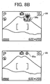
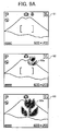
- FIGs. 8A and 8B are schematics for illustrating an example of an icon displayed in a different size when a function is changed from a default setting.
- a screen 81 is a normal display screen.
- an icon 82a indicating the close-up mode is displayed in an enlarged size at the beginning on a screen 82.
- the size of this icon changes to a smaller size like those of icons 83a to 85a shown on screens 83 to 85, and the icon is finally disposed at a predetermined position.
- the icon is displayed In a large size immediately after the setting is changed. The size of the icon becomes gradually smaller, and the small icon is displayed at a predetermined position. With this arrangement, the user can recognize the setting. After a predetermined time, the icon can be placed at a position where the icon does not hinder the photographing.
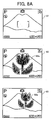
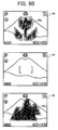
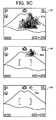
- FIGs. 9A to 9C are schematics for illustrating an example of an icon displayed in a different size when a setting of a photographing mode is changed from a close-up mode to a distant-view mode.
- a screen 91 is a normal display screen with the close-up mode being set.
- an icon indicating the distant-view mode so far being set is displayed In a small size at the beginning on a screen 92.
- the size of this icon changes to a larger size like those of icons 92a to 94a shown on screens 92 to 94, and the icon finally disappears as shown on a screen 95.
- the icon can be displayed in a low thickness while being enlarged, and can disappear is such a way that the icon fades out. This gives an impression to the user that the close-up mode disappears.
- an icon 96a that indicates the distant-view mode is displayed on a screen 96, and this icon gradually becomes larger like distant-view mode icons 97a to 99a shown on screens 97 to 99.
- the icon is displayed in a small size immediately after the setting is changed. The size of the Icon becomes gradually larger.
- the close-up mode and the distant-view mode can be switched over from each other by dynamically changing the size of the switched display, thereby giving an impression of the switchover.
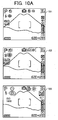
- Figs, 10A and 10B are schematics for illustrating a change of a screen from a change state set to a default setting.
- the setting change button (not shown)
- the set icons flicker on a screen 102.
- the set icons can be switched to an enlarged display shown on a screen 103.
- the user stops depressing the setting-change button the original screen 101 is obtained.
- a screen 104 for accepting the switchover to the default setting is displayed.
- an OK button (not shown)
- the operating unit 14 by moving a cursor to an OK display 104a on the screen 104, the setting by the operator is all canceled, and the original default setting is obtained.
- a screen 105 shows the returned default setting.
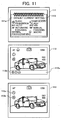
- Fig. 11 is a schematic for illustrating an example of a display of icons when photographing conditions are set differently from default conditions.
- a screen 111 shows both icons and character information by comparing the default setting with the set current state.
- a screen 112 has an area in which a display bar 112a is provided. Only an icon 112b of which setting is different from the default setting is displayed In this area.
- On a screen 113 an underline is provided to the icon of which setting is different from the default setting, thereby emphasizing this icon. Both the screen 112 and the screen 113 give display to emphasize the icon of which setting is changed from the default setting, thereby enabling the operator to easily recognize the change of the setting.
- the CPU 13 reads the OSD control program stored in the ROM 23 to retrieve the information-processing method of controlling the digital camera having a display unit that can display icons indicating the device state or the operating condition of the digital camera according to the OSD function. Based on the device condition determining function stored in the program, the change in the sate of the digital camera or the change in the setting of the operating condition is determined. Based on the function of assigning the icons, Icons that indicate the state or the operating condition of the digital camera of which change is determined is assigned. Based on the OSD display control function, the icons assigned are OSD displayed in a state different from that of the icons before the icons are assigned.
- the icons are displayed in a state different from that before the settings are changed.
- the user's visibility of confirming the changed setting improves. Further, the user can correctly determine the setting, thereby decreasing photographing errors attributable to erroneous setting by the user.
- the present invention user's visibility of confirming the setting change improves. Since the icons are displayed in the normal mode during a normal use, the user can correctly determine the setting, thus the icons do not hinder the display during the normal use.
- normal visibility is not hindered during a general use of the camera, and user's visibility of confirming the icons corresponding to the setting change improves.
- a user can recognize a kind of a setting condition in relation to a layout, thereby improving a recognition rate and decreasing an erroneous setting.
- a user can determine a setting or instruct a start of the device while being conscious about presence of a base image. Therefore, the user can determine an appropriate setting and instruct the starting correctly.
- an information-processing method for controlling an electronic apparatus with a display unit that improves user's visibility of confirming the setting change, and enables a user to correctly determine the setting.
- a computer can execute the information-processing method according to the invention.
Landscapes
- Engineering & Computer Science (AREA)
- Multimedia (AREA)
- Signal Processing (AREA)
- Human Computer Interaction (AREA)
- User Interface Of Digital Computer (AREA)
- Studio Devices (AREA)
- Indication In Cameras, And Counting Of Exposures (AREA)
- Digital Computer Display Output (AREA)
Applications Claiming Priority (4)
| Application Number | Priority Date | Filing Date | Title |
|---|---|---|---|
| JP2004080795 | 2004-03-19 | ||
| JP2004080795 | 2004-03-19 | ||
| JP2005038267A JP4095071B2 (ja) | 2004-03-19 | 2005-02-15 | ディスプレイ付き電子装置、ディスプレイ付き電子装置の制御方法、及びプログラム |
| JP2005038267 | 2005-02-15 |
Publications (1)
| Publication Number | Publication Date |
|---|---|
| EP1577876A1 true EP1577876A1 (en) | 2005-09-21 |
Family
ID=34840260
Family Applications (1)
| Application Number | Title | Priority Date | Filing Date |
|---|---|---|---|
| EP05005866A Ceased EP1577876A1 (en) | 2004-03-19 | 2005-03-17 | Electronic apparatus with display unit, information-processing method, and computer product |
Country Status (4)
| Country | Link |
|---|---|
| US (2) | US7493571B2 (https=) |
| EP (1) | EP1577876A1 (https=) |
| JP (1) | JP4095071B2 (https=) |
| CN (1) | CN100407770C (https=) |
Cited By (2)
| Publication number | Priority date | Publication date | Assignee | Title |
|---|---|---|---|---|
| EP2028839A3 (en) * | 2007-08-21 | 2009-12-23 | Samsung Electronics Co., Ltd. | Method of providing menu using touchscreen and multimedia apparatus applying the same |
| EP2579571A3 (en) * | 2011-10-03 | 2014-03-19 | Canon Kabushiki Kaisha | Image pickup information output apparatus and lens apparatus equipped with same |
Families Citing this family (100)
| Publication number | Priority date | Publication date | Assignee | Title |
|---|---|---|---|---|
| KR101120027B1 (ko) * | 2004-11-01 | 2012-03-23 | 삼성전자주식회사 | 셔터 반누름 시에 osd 처리 장치 및 방법 |
| KR101058024B1 (ko) * | 2004-11-18 | 2011-08-19 | 삼성전자주식회사 | 아이콘들이 적응적으로 디스플레이되는 디지털 촬영 장치및 그 제어 방법 |
| JP4776995B2 (ja) * | 2005-07-14 | 2011-09-21 | キヤノン株式会社 | コンピュータ装置およびその制御方法およびプログラム |
| USD577735S1 (en) * | 2005-07-18 | 2008-09-30 | Samsung Electronics Co., Ltd. | Display for a personal communication device |
| US7697827B2 (en) | 2005-10-17 | 2010-04-13 | Konicek Jeffrey C | User-friendlier interfaces for a camera |
| US7480870B2 (en) * | 2005-12-23 | 2009-01-20 | Apple Inc. | Indication of progress towards satisfaction of a user input condition |
| US7657849B2 (en) | 2005-12-23 | 2010-02-02 | Apple Inc. | Unlocking a device by performing gestures on an unlock image |
| JP4975330B2 (ja) * | 2006-01-30 | 2012-07-11 | 京セラ株式会社 | 表示装置、携帯電話機、及び文字サイズ変更方法 |
| JP4154431B2 (ja) * | 2006-02-15 | 2008-09-24 | キヤノン株式会社 | 撮像装置及び表示制御方法 |
| US20070220438A1 (en) * | 2006-03-08 | 2007-09-20 | Fuji Xerox Co., Ltd. | Icon generating device, computer readable medium storing program for generating icon and method for generating icon |
| USD557699S1 (en) * | 2006-03-23 | 2007-12-18 | Samsung Electronics Co., Ltd. | Graphic user interface for a digital camcorder |
| JP5176293B2 (ja) * | 2006-06-29 | 2013-04-03 | ソニー株式会社 | 表示装置および方法 |
| JP4764787B2 (ja) * | 2006-09-06 | 2011-09-07 | キヤノン株式会社 | 撮像装置、撮像装置の表示制御方法、及びコンピュータプログラム |
| KR101315463B1 (ko) * | 2006-12-20 | 2013-10-14 | 삼성전자주식회사 | 화상형성제어장치 및 그 제어방법 |
| JP4274238B2 (ja) | 2006-12-22 | 2009-06-03 | ソニー株式会社 | 画像処理装置及び画像処理方法、並びにコンピュータ・プログラム |
| JP4773943B2 (ja) * | 2006-12-27 | 2011-09-14 | キヤノン株式会社 | 画像再生装置及びその制御方法 |
| US20080174427A1 (en) * | 2007-01-20 | 2008-07-24 | Banerjee Dwip N | Intelligent automated method for securing confidential and sensitive information displayed on a computer monitor |
| JP4728992B2 (ja) * | 2007-03-28 | 2011-07-20 | Necフィールディング株式会社 | 携帯情報端末および表示方法 |
| USD604305S1 (en) * | 2007-06-23 | 2009-11-17 | Apple Inc. | Graphical user interface for a display screen or portion thereof |
| USD620020S1 (en) * | 2007-06-23 | 2010-07-20 | Apple Inc. | Graphical user interface for a display screen or portion thereof |
| JP5144146B2 (ja) * | 2007-07-02 | 2013-02-13 | ホーチキ株式会社 | 防災表示装置及び制御方法 |
| KR20250099420A (ko) | 2007-09-24 | 2025-07-01 | 애플 인크. | 전자 장치 내의 내장형 인증 시스템들 |
| CN101409787B (zh) * | 2007-10-11 | 2010-08-25 | 佛山普立华科技有限公司 | 自定义屏幕显示界面的系统及方法 |
| JP4596280B2 (ja) * | 2007-12-14 | 2010-12-08 | ソニー株式会社 | 映像出力装置及び映像出力装置のメニュー画面強制表示方法 |
| US8130111B2 (en) * | 2007-12-19 | 2012-03-06 | Bank Of America Corporation | Services portal |
| JP4843002B2 (ja) * | 2008-01-25 | 2011-12-21 | ソニー株式会社 | 撮像装置、および撮像装置制御方法、並びにコンピュータ・プログラム |
| JP4687725B2 (ja) | 2008-02-12 | 2011-05-25 | ソニー株式会社 | 画像処理装置及び画像処理方法、並びにコンピュータ・プログラム |
| US8174503B2 (en) | 2008-05-17 | 2012-05-08 | David H. Cain | Touch-based authentication of a mobile device through user generated pattern creation |
| US8520979B2 (en) * | 2008-08-19 | 2013-08-27 | Digimarc Corporation | Methods and systems for content processing |
| JP5043787B2 (ja) * | 2008-09-16 | 2012-10-10 | キヤノン株式会社 | 撮影装置及びその制御方法 |
| JP4697289B2 (ja) | 2008-11-05 | 2011-06-08 | ソニー株式会社 | 撮像装置、撮像装置の表示制御方法 |
| USD606080S1 (en) * | 2008-11-24 | 2009-12-15 | Microsoft Corporation | User interface for a portion of a display screen |
| JP5276536B2 (ja) | 2009-07-16 | 2013-08-28 | 富士フイルム株式会社 | 3次元画像表示装置及び3次元画像表示方法 |
| JP5322817B2 (ja) | 2009-07-17 | 2013-10-23 | 富士フイルム株式会社 | 3次元画像撮像装置及び3次元画像表示方法 |
| JP2011028345A (ja) * | 2009-07-22 | 2011-02-10 | Olympus Imaging Corp | 条件変更装置、カメラ、携帯機器、およびプログラム |
| US8638939B1 (en) | 2009-08-20 | 2014-01-28 | Apple Inc. | User authentication on an electronic device |
| USD666209S1 (en) | 2010-06-05 | 2012-08-28 | Apple Inc. | Display screen or portion thereof with graphical user interface |
| US8528072B2 (en) | 2010-07-23 | 2013-09-03 | Apple Inc. | Method, apparatus and system for access mode control of a device |
| JP5633679B2 (ja) * | 2010-09-03 | 2014-12-03 | カシオ計算機株式会社 | 撮像装置およびプログラム |
| USD657372S1 (en) * | 2010-09-17 | 2012-04-10 | Samsung Electronics Co., Ltd. | Mobile terminal with graphical user interface |
| US8587547B2 (en) | 2010-11-05 | 2013-11-19 | Apple Inc. | Device, method, and graphical user interface for manipulating soft keyboards |
| US8547354B2 (en) | 2010-11-05 | 2013-10-01 | Apple Inc. | Device, method, and graphical user interface for manipulating soft keyboards |
| CN102541414A (zh) * | 2010-12-28 | 2012-07-04 | 英华达(上海)科技有限公司 | 一种能自动切换操作模式的移动终端装置 |
| US9092132B2 (en) | 2011-01-24 | 2015-07-28 | Apple Inc. | Device, method, and graphical user interface with a dynamic gesture disambiguation threshold |
| US8638385B2 (en) | 2011-06-05 | 2014-01-28 | Apple Inc. | Device, method, and graphical user interface for accessing an application in a locked device |
| USD660871S1 (en) * | 2011-08-31 | 2012-05-29 | Nike, Inc. | Display screen with icon |
| JP2013145449A (ja) * | 2012-01-13 | 2013-07-25 | Sharp Corp | 情報端末装置 |
| US9213822B2 (en) | 2012-01-20 | 2015-12-15 | Apple Inc. | Device, method, and graphical user interface for accessing an application in a locked device |
| JP5959217B2 (ja) * | 2012-02-07 | 2016-08-02 | オリンパス株式会社 | 撮像装置及び画質調整方法、画質調整プログラム |
| USD709095S1 (en) | 2012-02-09 | 2014-07-15 | Apple Inc. | Display screen or portion thereof with icon |
| JP5655175B2 (ja) * | 2012-04-09 | 2015-01-14 | 富士フイルム株式会社 | 携帯型電子機器及び表示制御方法 |
| EP2670118A1 (en) * | 2012-05-28 | 2013-12-04 | Doro AB | Improved status notification for a mobile communications terminal |
| JP5942614B2 (ja) | 2012-06-05 | 2016-06-29 | 株式会社リコー | 情報処理装置、システム及びプログラム |
| JP2014067266A (ja) * | 2012-09-26 | 2014-04-17 | Kyocera Corp | 電子機器、制御方法、及び制御プログラム |
| WO2014065127A1 (ja) * | 2012-10-22 | 2014-05-01 | ソニー株式会社 | 情報処理端末、撮像機、情報処理方法、プログラム、および遠隔撮像システム |
| KR101890137B1 (ko) * | 2012-10-25 | 2018-08-21 | 삼성전자주식회사 | 촬영 장치 및 제어 방법 |
| UA26857S (uk) * | 2013-02-23 | 2014-04-25 | Самсунг Елєктро& | Значок графічного користувацького інтерфейсу дисплея на мобільному пристрою зв'язку |
| AU349936S (en) * | 2013-02-23 | 2013-07-29 | Samsung Electronics Co Ltd | Display screen with icon for an electronic device |
| AU349938S (en) * | 2013-02-23 | 2013-07-29 | Samsung Electronics Co Ltd | Display screen with icon for an electronic device |
| TWD165005S (zh) * | 2013-03-27 | 2014-12-21 | 三星電子股份有限公司 | 顯示面板之圖像 |
| USD738905S1 (en) | 2013-06-09 | 2015-09-15 | Apple Inc. | Display screen or portion thereof with animated graphical user interface |
| USD745894S1 (en) * | 2013-09-03 | 2015-12-22 | Samsung Electronics Co., Ltd. | Display screen or portion thereof with icon |
| USD746831S1 (en) | 2013-09-10 | 2016-01-05 | Apple Inc. | Display screen or portion thereof with graphical user interface |
| USD711427S1 (en) | 2013-10-22 | 2014-08-19 | Apple Inc. | Display screen or portion thereof with icon |
| USD810115S1 (en) | 2013-11-22 | 2018-02-13 | Apple Inc. | Display screen or portion thereof with graphical user interface |
| USD771112S1 (en) | 2014-06-01 | 2016-11-08 | Apple Inc. | Display screen or portion thereof with graphical user interface |
| USD753678S1 (en) | 2014-06-01 | 2016-04-12 | Apple Inc. | Display screen or portion thereof with animated graphical user interface |
| KR102418119B1 (ko) | 2014-08-25 | 2022-07-07 | 삼성전자 주식회사 | 시계 화면 구성 방법 및 이를 구현한 웨어러블 전자장치 |
| JP6514521B2 (ja) * | 2015-02-19 | 2019-05-15 | オリンパス株式会社 | 表示制御装置 |
| JP6032319B2 (ja) * | 2015-04-17 | 2016-11-24 | ソニー株式会社 | 情報処理装置、情報処理方法およびプログラム |
| CN105824519A (zh) * | 2015-06-29 | 2016-08-03 | 维沃移动通信有限公司 | 电子设备的交互方法及电子设备 |
| US10254918B2 (en) * | 2015-08-27 | 2019-04-09 | Kyocera Document Solutions Inc. | Tilt adjustable perspective icons display device and non-transitory computer readable medium |
| USD788161S1 (en) | 2015-09-08 | 2017-05-30 | Apple Inc. | Display screen or portion thereof with graphical user interface |
| USD791829S1 (en) * | 2015-12-23 | 2017-07-11 | Samsung Electronics Co., Ltd. | Display screen or portion thereof with graphical user interface |
| USD791828S1 (en) * | 2015-12-23 | 2017-07-11 | Samsung Electronics Co., Ltd. | Display screen or portion thereof with graphical user interface |
| USD802019S1 (en) * | 2016-04-28 | 2017-11-07 | Rubicon Global Holdings, Llc | Display screen with animated icon |
| US10055186B2 (en) * | 2016-06-01 | 2018-08-21 | Dell Products, Lp | Mitigation of image degradation in displays |
| EP3343286B1 (en) * | 2016-12-27 | 2021-08-18 | Canon Kabushiki Kaisha | Display control apparatus and control method therefor |
| USD851111S1 (en) | 2017-09-09 | 2019-06-11 | Apple Inc. | Electronic device with graphical user interface |
| USD843442S1 (en) | 2017-09-10 | 2019-03-19 | Apple Inc. | Type font |
| USD845991S1 (en) | 2017-09-26 | 2019-04-16 | Google Llc | Display screen with animated icon |
| JP6439853B2 (ja) * | 2017-12-26 | 2018-12-19 | 富士ゼロックス株式会社 | 処理装置およびプログラム |
| USD879132S1 (en) | 2018-06-03 | 2020-03-24 | Apple Inc. | Electronic device with graphical user interface |
| JP6865721B2 (ja) * | 2018-07-27 | 2021-04-28 | 任天堂株式会社 | プログラム、情報処理装置、情報処理方法、および、情報処理システム |
| USD938968S1 (en) | 2018-09-06 | 2021-12-21 | Apple Inc. | Electronic device with animated graphical user interface |
| CN109656498B (zh) * | 2018-10-30 | 2021-12-03 | 努比亚技术有限公司 | 一种显示控制方法、柔性屏终端及计算机可读存储介质 |
| USD895656S1 (en) * | 2018-12-26 | 2020-09-08 | Michael Allen | Display panel portion with a computer-generated icon |
| USD902221S1 (en) | 2019-02-01 | 2020-11-17 | Apple Inc. | Electronic device with animated graphical user interface |
| USD900871S1 (en) | 2019-02-04 | 2020-11-03 | Apple Inc. | Electronic device with animated graphical user interface |
| CN111930376B (zh) * | 2019-05-13 | 2025-03-04 | 微软技术许可有限责任公司 | 风格化图标的自动生成 |
| USD913315S1 (en) | 2019-05-31 | 2021-03-16 | Apple Inc. | Electronic device with graphical user interface |
| USD924912S1 (en) | 2019-09-09 | 2021-07-13 | Apple Inc. | Display screen or portion thereof with graphical user interface |
| JP7541095B2 (ja) * | 2020-07-22 | 2024-08-27 | 富士フイルム株式会社 | 撮像装置、及びプログラム |
| JP7309969B2 (ja) * | 2021-01-05 | 2023-07-18 | 楽天グループ株式会社 | 表示制御装置、表示制御方法、及びプログラム |
| CN115605836A (zh) * | 2021-01-05 | 2023-01-13 | 乐天集团股份有限公司(Jp) | 显示控制装置、显示控制方法以及程序 |
| USD973681S1 (en) * | 2021-03-30 | 2022-12-27 | The Government of the United States of America, as represented by the Secretary of Homeland Security | Display screen or portion thereof with a graphical user interface |
| USD1066397S1 (en) * | 2022-08-17 | 2025-03-11 | Atieva, Inc. | Automobile display screen with graphical user interface |
| JP1772165S (ja) * | 2022-09-27 | 2024-06-05 | 画面パネル表示用ズーム機能付き動画グラフィカルユーザーインターフェース | |
| JP1772164S (ja) * | 2022-09-27 | 2024-06-05 | 表示画面パネル用制御機能付き動画グラフィカルユーザーインターフェース | |
| USD1119941S1 (en) | 2024-05-07 | 2026-03-24 | Apple Inc. | Display screen or portion thereof with graphical user interface |
Citations (7)
| Publication number | Priority date | Publication date | Assignee | Title |
|---|---|---|---|---|
| US5923737A (en) | 1995-08-31 | 1999-07-13 | U.S. Philips Corporation | Terminal |
| US6091450A (en) * | 1996-06-14 | 2000-07-18 | Canon Kabushiki Kaisha | Image pickup apparatus having function of detecting proximity of eye |
| JP2002223403A (ja) * | 2001-01-29 | 2002-08-09 | Fuji Photo Film Co Ltd | 電子カメラ |
| EP1246434A1 (en) * | 2001-03-27 | 2002-10-02 | Sony International (Europe) GmbH | Protection system against unauthorised use of a mobile telephone |
| JP2003101824A (ja) * | 2001-09-25 | 2003-04-04 | Sanyo Electric Co Ltd | デジタルカメラ |
| EP1315369A1 (en) * | 2001-10-29 | 2003-05-28 | Samsung Electronics Co., Ltd. | User-configurable electronic apparatus |
| US6600499B1 (en) | 2000-04-13 | 2003-07-29 | International Business Machines Corp. | Method and system for displaying status of critical indicators on diverse display devices and indicating changes in status |
Family Cites Families (35)
| Publication number | Priority date | Publication date | Assignee | Title |
|---|---|---|---|---|
| US5182641A (en) * | 1991-06-17 | 1993-01-26 | The United States Of America As Represented By The Administrator Of The National Aeronautics And Space Administration | Composite video and graphics display for camera viewing systems in robotics and teleoperation |
| US6630949B1 (en) * | 1992-12-01 | 2003-10-07 | Canon Kabushiki Kaisha | Image processing system and information processing apparatus |
| US5564004A (en) * | 1994-04-13 | 1996-10-08 | International Business Machines Corporation | Method and system for facilitating the selection of icons |
| US5565888A (en) * | 1995-02-17 | 1996-10-15 | International Business Machines Corporation | Method and apparatus for improving visibility and selectability of icons |
| US5977976A (en) * | 1995-04-19 | 1999-11-02 | Canon Kabushiki Kaisha | Function setting apparatus |
| US5706457A (en) * | 1995-06-07 | 1998-01-06 | Hughes Electronics | Image display and archiving system and method |
| US6118888A (en) * | 1997-02-28 | 2000-09-12 | Kabushiki Kaisha Toshiba | Multi-modal interface apparatus and method |
| JPH11119316A (ja) | 1997-10-20 | 1999-04-30 | Asahi Optical Co Ltd | マクロ撮影可能なデジタルスチルカメラ |
| JPH11146234A (ja) | 1997-11-12 | 1999-05-28 | Ricoh Co Ltd | デジタルカメラ |
| KR100251962B1 (ko) * | 1997-12-29 | 2000-04-15 | 윤종용 | 웹 비디오 폰에서 메모리 스와핑 방법 |
| JPH11275394A (ja) | 1998-03-23 | 1999-10-08 | Canon Inc | メニュー表示装置、ビデオカメラ及びコンピュータ読み取り可能な記憶媒体 |
| US6417869B1 (en) * | 1998-04-15 | 2002-07-09 | Citicorp Development Center, Inc. | Method and system of user interface for a computer |
| JP2000010174A (ja) * | 1998-06-17 | 2000-01-14 | Minolta Co Ltd | カメラ及びカメラシステム |
| US6453078B2 (en) * | 1998-08-28 | 2002-09-17 | Eastman Kodak Company | Selecting, arranging, and printing digital images from thumbnail images |
| EP1052849B1 (en) * | 1998-11-30 | 2011-06-15 | Sony Corporation | Set-top box and method for operating same |
| JP2000347974A (ja) | 1999-03-31 | 2000-12-15 | Sony Corp | 情報共有処理方法、情報共有処理プログラム格納媒体、情報共有処理装置、および情報共有処理システム |
| JP2001067163A (ja) | 1999-08-25 | 2001-03-16 | Sony Corp | 情報処理装置および情報処理方法、並びに記録媒体 |
| JP2001211354A (ja) | 2000-01-26 | 2001-08-03 | Nikon Corp | 電子カメラ |
| US7155676B2 (en) * | 2000-12-19 | 2006-12-26 | Coolernet | System and method for multimedia authoring and playback |
| JP2002209138A (ja) | 2001-01-12 | 2002-07-26 | Minolta Co Ltd | デジタルカメラ |
| JP2002290784A (ja) | 2001-03-28 | 2002-10-04 | Sony Corp | 撮影装置 |
| WO2002101534A1 (en) * | 2001-06-12 | 2002-12-19 | Idelix Software Inc. | Graphical user interface with zoom for detail-in-context presentations |
| JP2003044207A (ja) * | 2001-07-26 | 2003-02-14 | Fujitsu Ltd | 携帯端末及び携帯端末の通信接続方法 |
| JP3653073B2 (ja) | 2001-10-22 | 2005-05-25 | 株式会社リコー | 画像形成装置、利用者制限方法およびこの方法をコンピュータに実行させるプログラム |
| US7036080B1 (en) * | 2001-11-30 | 2006-04-25 | Sap Labs, Inc. | Method and apparatus for implementing a speech interface for a GUI |
| JP2003244354A (ja) | 2002-02-18 | 2003-08-29 | Ricoh Co Ltd | 画像形成装置 |
| IES20020159A2 (en) * | 2002-03-01 | 2003-09-03 | Baydon Solutions Ltd | Content management system |
| JP2003333380A (ja) | 2002-05-08 | 2003-11-21 | Olympus Optical Co Ltd | 撮像装置、撮影画像確認方法、及びプログラム |
| JP2004021554A (ja) | 2002-06-14 | 2004-01-22 | Canon Inc | 画像入出力装置および画像入出力装置の制御方法 |
| JP2004061762A (ja) | 2002-07-26 | 2004-02-26 | Fuji Photo Film Co Ltd | デジタルカメラ |
| US7044459B2 (en) * | 2002-11-22 | 2006-05-16 | Scott Edward Watson | Simplified flexural pivot |
| JP2004206688A (ja) * | 2002-12-12 | 2004-07-22 | Fuji Photo Film Co Ltd | 顔認識方法、顔切出方法、および撮像装置 |
| US7155336B2 (en) * | 2004-03-24 | 2006-12-26 | A9.Com, Inc. | System and method for automatically collecting images of objects at geographic locations and displaying same in online directories |
| JP2006047602A (ja) | 2004-08-04 | 2006-02-16 | Casio Comput Co Ltd | カメラ装置 |
| JP2006086758A (ja) | 2004-09-15 | 2006-03-30 | Nikon Corp | 電子カメラ |
-
2005
- 2005-02-15 JP JP2005038267A patent/JP4095071B2/ja not_active Expired - Lifetime
- 2005-03-15 CN CN2005100558288A patent/CN100407770C/zh not_active Expired - Fee Related
- 2005-03-17 EP EP05005866A patent/EP1577876A1/en not_active Ceased
- 2005-03-18 US US11/082,781 patent/US7493571B2/en active Active
-
2007
- 2007-10-31 US US11/933,059 patent/US8327283B2/en not_active Expired - Fee Related
Patent Citations (8)
| Publication number | Priority date | Publication date | Assignee | Title |
|---|---|---|---|---|
| US5923737A (en) | 1995-08-31 | 1999-07-13 | U.S. Philips Corporation | Terminal |
| US6091450A (en) * | 1996-06-14 | 2000-07-18 | Canon Kabushiki Kaisha | Image pickup apparatus having function of detecting proximity of eye |
| US6600499B1 (en) | 2000-04-13 | 2003-07-29 | International Business Machines Corp. | Method and system for displaying status of critical indicators on diverse display devices and indicating changes in status |
| JP2002223403A (ja) * | 2001-01-29 | 2002-08-09 | Fuji Photo Film Co Ltd | 電子カメラ |
| EP1246434A1 (en) * | 2001-03-27 | 2002-10-02 | Sony International (Europe) GmbH | Protection system against unauthorised use of a mobile telephone |
| JP2003101824A (ja) * | 2001-09-25 | 2003-04-04 | Sanyo Electric Co Ltd | デジタルカメラ |
| US20040264952A1 (en) * | 2001-09-25 | 2004-12-30 | Hideshi Oeda | Digital camera |
| EP1315369A1 (en) * | 2001-10-29 | 2003-05-28 | Samsung Electronics Co., Ltd. | User-configurable electronic apparatus |
Non-Patent Citations (2)
| Title |
|---|
| "Digital Camera FinePix S5000", INTERNET CITATION, July 2003 (2003-07-01), XP002383324, Retrieved from the Internet <URL:http://www.fujifilmusa.com/shared/bin/S5000Manual.pdf> [retrieved on 20060531] * |
| PATENT ABSTRACTS OF JAPAN vol. 2002, no. 12 12 December 2002 (2002-12-12) * |
Cited By (4)
| Publication number | Priority date | Publication date | Assignee | Title |
|---|---|---|---|---|
| EP2028839A3 (en) * | 2007-08-21 | 2009-12-23 | Samsung Electronics Co., Ltd. | Method of providing menu using touchscreen and multimedia apparatus applying the same |
| EP2579571A3 (en) * | 2011-10-03 | 2014-03-19 | Canon Kabushiki Kaisha | Image pickup information output apparatus and lens apparatus equipped with same |
| US9172861B2 (en) | 2011-10-03 | 2015-10-27 | Canon Kabushiki Kaisha | Image pickup information output apparatus and lens apparatus equipped with same |
| US9817207B2 (en) | 2011-10-03 | 2017-11-14 | Canon Kabushiki Kaisha | Image pickup information output apparatus and lens apparatus equipped with same |
Also Published As
| Publication number | Publication date |
|---|---|
| US20080072172A1 (en) | 2008-03-20 |
| JP4095071B2 (ja) | 2008-06-04 |
| JP2005301992A (ja) | 2005-10-27 |
| CN1671185A (zh) | 2005-09-21 |
| US20050216862A1 (en) | 2005-09-29 |
| CN100407770C (zh) | 2008-07-30 |
| US7493571B2 (en) | 2009-02-17 |
| US8327283B2 (en) | 2012-12-04 |
Similar Documents
| Publication | Publication Date | Title |
|---|---|---|
| US7493571B2 (en) | Electronic apparatus with display unit, information-processing method, and computer product | |
| JP2005301992A5 (https=) | ||
| US7432972B2 (en) | Method of controlling digital photographing apparatus, and digital photographing apparatus utilizing the method | |
| JP2009177328A (ja) | 撮像装置 | |
| JP4730663B2 (ja) | 遠隔制御装置、遠隔制御システムおよび遠隔制御方法 | |
| TW200413829A (en) | Image display device and image display method | |
| US10334336B2 (en) | Method of controlling digital photographing apparatus and digital photographing apparatus using the same | |
| KR20040046859A (ko) | Pip화면을 이용한 듀얼모드 신호처리장치 | |
| JP2005260960A (ja) | Osdメニューを表示する映像撮影機器およびその表示方法 | |
| JP2008078712A (ja) | 撮影装置および方法並びにプログラム | |
| JP2009077226A (ja) | 撮像装置とその制御方法及びプログラム及びプログラムを記憶した記憶媒体 | |
| JP4330049B2 (ja) | 電子カメラ装置、情報配置方法及びコンピュータ読み取り可能な記録媒体 | |
| JP4181206B2 (ja) | 撮影機能付き電子装置、撮影機能付き電子装置の制御方法、及び、プログラム | |
| JP4778022B2 (ja) | 撮影機能付き電子装置、撮影機能付き電子装置の制御方法、及び、プログラム | |
| JP2007194804A (ja) | 撮影装置および方法、再生装置および方法、並びにプログラム | |
| JP5024332B2 (ja) | 撮影装置および方法、再生装置および方法、並びにプログラム | |
| US7554581B2 (en) | Method of controlling a camera for users having impaired vision | |
| JP2001242529A (ja) | 画像記録装置 | |
| JP2009088688A (ja) | 撮像装置及びその撮像方法並びにその設定切替方法 | |
| JP3913046B2 (ja) | 撮像装置 | |
| JP2005328225A (ja) | デジタルカメラ | |
| JP2012134835A (ja) | 撮像装置、その制御方法及びプログラム | |
| JP2013207350A (ja) | 動画撮影装置 | |
| JP2007214690A (ja) | 表示装置及び表示方法 | |
| JP2007036427A (ja) | 撮影装置 |
Legal Events
| Date | Code | Title | Description |
|---|---|---|---|
| PUAI | Public reference made under article 153(3) epc to a published international application that has entered the european phase |
Free format text: ORIGINAL CODE: 0009012 |
|
| AK | Designated contracting states |
Kind code of ref document: A1 Designated state(s): AT BE BG CH CY CZ DE DK EE ES FI FR GB GR HU IE IS IT LI LT LU MC NL PL PT RO SE SI SK TR |
|
| AX | Request for extension of the european patent |
Extension state: AL BA HR LV MK YU |
|
| 17P | Request for examination filed |
Effective date: 20060321 |
|
| AKX | Designation fees paid |
Designated state(s): DE FR GB |
|
| 17Q | First examination report despatched |
Effective date: 20100920 |
|
| STAA | Information on the status of an ep patent application or granted ep patent |
Free format text: STATUS: THE APPLICATION HAS BEEN REFUSED |
|
| 18R | Application refused |
Effective date: 20131210 |