EP1577423B1 - Elektrolytische Zelle zur Gaserzeugung - Google Patents
Elektrolytische Zelle zur Gaserzeugung Download PDFInfo
- Publication number
- EP1577423B1 EP1577423B1 EP05003729A EP05003729A EP1577423B1 EP 1577423 B1 EP1577423 B1 EP 1577423B1 EP 05003729 A EP05003729 A EP 05003729A EP 05003729 A EP05003729 A EP 05003729A EP 1577423 B1 EP1577423 B1 EP 1577423B1
- Authority
- EP
- European Patent Office
- Prior art keywords
- cell according
- electrodes
- electrolyte liquid
- gas
- azide
- Prior art date
- Legal status (The legal status is an assumption and is not a legal conclusion. Google has not performed a legal analysis and makes no representation as to the accuracy of the status listed.)
- Expired - Lifetime
Links
Images

Classifications
-
- C—CHEMISTRY; METALLURGY
- C25—ELECTROLYTIC OR ELECTROPHORETIC PROCESSES; APPARATUS THEREFOR
- C25B—ELECTROLYTIC OR ELECTROPHORETIC PROCESSES FOR THE PRODUCTION OF COMPOUNDS OR NON-METALS; APPARATUS THEREFOR
- C25B1/00—Electrolytic production of inorganic compounds or non-metals
-
- A—HUMAN NECESSITIES
- A44—HABERDASHERY; JEWELLERY
- A44B—BUTTONS, PINS, BUCKLES, SLIDE FASTENERS, OR THE LIKE
- A44B19/00—Slide fasteners
- A44B19/24—Details
- A44B19/26—Sliders
- A44B19/265—Sliders with means for preventing the accidental intrusion of material into the slider body, e.g. with shield or guard
-
- C—CHEMISTRY; METALLURGY
- C25—ELECTROLYTIC OR ELECTROPHORETIC PROCESSES; APPARATUS THEREFOR
- C25B—ELECTROLYTIC OR ELECTROPHORETIC PROCESSES FOR THE PRODUCTION OF COMPOUNDS OR NON-METALS; APPARATUS THEREFOR
- C25B1/00—Electrolytic production of inorganic compounds or non-metals
- C25B1/01—Products
-
- A—HUMAN NECESSITIES
- A45—HAND OR TRAVELLING ARTICLES
- A45B—WALKING STICKS; UMBRELLAS; LADIES' OR LIKE FANS
- A45B25/00—Details of umbrellas
- A45B25/18—Covers; Means for fastening same
Definitions
- the invention relates to a cell for generating gas, in particular for the operation of a lubricant dispenser, with two electrodes for connection to a current source containing circuit and an aqueous electrolyte liquid containing an azide of the formula XN 3 and located between the two electrodes for the electrochemical generation of a gas containing nitrogen (N 2 ).
- a gas generating cell it is known to meter the amount of lubricant dispensed from a lubricant dispenser by means of a gas generating cell, the pressure generated by the gas causing a corresponding escape of lubricant from the dispenser.
- the generation of hydrogen or oxygen at the electrodes of a galvanic cell is known ( DE 35 32 335 C2 ).
- the cell may optionally provide a sufficiently large voltage with a zinc anode to generate hydrogen or with a manganese dioxide cathode to produce oxygen to adjust the electrolytic current flowing between the electrodes via an external variable resistor.
- a battery may be provided, which allows a better control of the current.
- the invention is based on the object to provide a cell with the features described above, which is characterized by a good gas generation rate.
- the object is achieved in that the electrolyte liquid contains a magnesium salt as an additive for the chemical bonding of hydroxide ions formed during the electrochemical reaction.
- the invention is based on the finding that the magnesium hydroxide formed from the magnesium salt and the hydroxide ions has only a very small solubility product and is removed in accordance with the reaction equilibrium in the electrolyte liquid.
- magnesium in its compounds is electrochemically indifferent and also the precipitated hydrous hydroxide hydroxide does not affect the ion migration in the electrolyte liquid appreciably. With the aid of the teaching according to the invention, it is possible to keep the pH of the electrolyte liquid constant even with increasing nitrogen formation in a narrow range.
- the electrolyte liquid may have a pH between 8 and 10.
- the pH is 8 - 9.5.
- the azide is expediently sodium azide
- the magnesium salt used is preferably magnesium sulfate or magnesium perchlorate. In order to ensure a sufficient removal of the resulting hydroxide ions from the electrolyte liquid, the magnesium salt is added stoichiometrically or in excess in relation to the amount of azide.
- the electrolyte liquid may be added to an antifreeze, which preferably consists of ethylene glycol and / or dimethyl sulfoxide. As a result, proper operation of the gas cell is ensured even at low temperatures.
- the electrolyte liquid may contain nickel sulfate as an additive.
- the direct oxidation of azide is possible not only on noble metal electrodes, but equally well on electrodes made of steel, preferably chromium-nickel steel or graphite. Alternatively, the electrodes can also be made of plastic with embedded graphite powder.
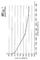
- Fig. 1 a diagram is shown, which represents the evolution of gas from a pure sodium azide solution according to the prior art as a function of the content of free sodium hydroxide solution.
- the case of the decay of the azide according to the equation 2 NaN 3 + 2 H 2 O ⁇ 3N 2 + H 2 + 2 NaOH The caustic soda produced causes even at low concentrations a significant drop in the gas generation rate, so that as the gas production increases, the effectiveness of the cell decreases very rapidly.
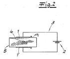
- the Fig. 2 schematically shows the structure of a cell according to the invention for gas generation, which is particularly suitable for the operation of a lubricant dispenser.
- the cell has two electrodes 1, 1 'for connection to a circuit 3 containing a current source 2.
- the power source 2 may for example consist of a commercially available battery button cell.
- a sodium azide (NaN 3 ) -containing Between the two electrodes 1, 1 'there is a sodium azide (NaN 3 ) -containing, aqueous electrolyte liquid 4, which serves for the electrochemical generation of a nitrogen (N 2 ) -containing gas.
- a suitable receiving body 5 is provided, for receiving the electrolyte liquid 4, for receiving the electrolyte liquid 4, for receiving the electrolyte liquid 4, for receiving the electrolyte liquid 4, for receiving the electrolyte liquid 4, for receiving the electrolyte liquid 4, for receiving the electrolyte liquid 4, a suitable receiving body 5 is provided, for.
- the applied voltage causes the following reaction at the anode 1: 2N 3 - ⁇ 3N 2 + 2e - , while a corresponding reduction of hydrogen ions takes place at the cathode 1 ': 2 H + + 2e - ⁇ H 2
- the electrolyte liquid 4 is added to a magnesium salt for chemical bonding of the hydroxide ions formed during the electrochemical reaction.
- Magnesium hydroxide has a very low solubility product, so that the magnesium hydroxide formed from the magnesium salt and the hydroxide ions according to the equation Mg 2+ + 2OH - ⁇ Mg (OH) 2 , which is formed on the cathode 1 ', from the electrolyte liquid 4 fails.
- the electrolyte fluid according to the invention allows for the electrodes 1, 1 'conventional materials such.
- steel preferably chromium-nickel steel, or graphite can be used.
- the electrodes 1, 1 ' may also be made of plastic with embedded graphite powder.
- the magnesium perchlorate binds the sodium hydroxide formed in the reaction by the formation of sparingly soluble magnesium hydroxide. This precipitates as precipitate and is thereby removed from the reaction equilibrium.
- magnesium perchlorate has the advantage that the electrolyte liquid remains fluid to below - 20 ° C, so that an addition of antifreeze is not required and the electrolyte liquid can be easily absorbed in a sponge.
- a simple separation of gas and electrolyte fluid independent of the position is provided.
- the disposal of a cell containing the electrolyte liquid can be made by burning.
- the magnesium perchlorate is readily soluble in the water so that the volume of electrolyte can be kept small. Even at temperatures of - 20 ° C, the liquid has sufficient conductivity.
- Perchloric acid is also a stable compound that behaves inertly under the given conditions.
- the formation of elemental nitrogen is carried out according to the following reaction equation: 2 Na N 3 + Mg (ClO 4 ) 2 + 2H 2 O ⁇ 3 N 2 + H 2 + Mg (OH) 2 + 2 Na ClO 4 .
- the solution is slightly alkaline, hygroscopic, odorless, non-aggressive and undecomposed. Depending on the experimental conditions, 1 ml of this solution can supply 75 to 100 ml of gas (N 2 and H 2 ).
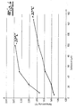
- the Fig. 3 illustrates the effect of adding nickel sulfate according to Example b) on the total cell voltage as a function of the electrolysis current strength.
- graphite electrodes 10 ⁇ 10 mm were used. From the Fig. 3 It can be seen that the addition of nickel sulfate, the hydrogen overvoltage of the electrode forming the cathode can be reduced and at the same cell current compared to the solution a) sets a correspondingly lower cell voltage.
- Fig. 4 illustrates the course of the cell voltage as a function of the current at + 20 ° C and - 20 ° C. It can be seen that lowering the temperature at the same cell current requires a higher cell voltage.
- This in Fig. 4 Diagram shown was prepared for the electrolyte liquid according to Example b), which ensures even at -20 ° C still sufficiently large cell currents that allow use of the cell according to the invention.
Landscapes
- Chemical & Material Sciences (AREA)
- Inorganic Chemistry (AREA)
- Engineering & Computer Science (AREA)
- Chemical Kinetics & Catalysis (AREA)
- Electrochemistry (AREA)
- Materials Engineering (AREA)
- Metallurgy (AREA)
- Organic Chemistry (AREA)
- Electrolytic Production Of Non-Metals, Compounds, Apparatuses Therefor (AREA)
- Lubricants (AREA)
Description
- Die Erfindung betrifft eine Zelle zur Gaserzeugung, insbesondere für den Betrieb eines Schmierstoffspenders, mit
zwei Elektroden zum Anschluss an einen eine Stromquelle enthaltenden Stromkreis und
einer zwischen den beiden Elektroden befindlichen, ein Azid der Formel XN3 enthaltenden, wässrigen Elektrolytflüssigkeit zur elektrochemischen Erzeugung eines Stickstoff (N2) enthaltenden Gases. - In der Praxis ist es bekannt, die von einem Schmierstoffspender abgegebene Schmierstoffmenge mittels einer ein Gas erzeugenden Zelle zu dosieren, wobei der mit Hilfe des Gases erzeugte Druck einen entsprechenden Austritt von Schmierstoff aus dem Spender verursacht. In diesem Zusammenhang ist beispielsweise die Erzeugung von Wasserstoff oder Sauerstoff an den Elektroden einer galvanischen Zelle bekannt (
DE 35 32 335 C2 ). Die Zelle kann ggf. mit einer Zinkanode zur Erzeugung von Wasserstoff oder mit einer Mangandioxidkathode zur Erzeugung von Sauerstoff selbst eine ausreichend große Spannung liefern, um über einen äußeren regelbaren Widerstand den zwischen den Elektroden fließenden Elektrolysestrom einzustellen. Zusätzlich kann auch eine Batterie vorgesehen sein, welche eine bessere Regelung der Stromstärke ermöglicht. - Aus der Druckschrift
DE 692 26 770 T2 ist eine Gaszelle bekannt, bei der durch Elektrolyse aus einer Natriumazidlösung Stickstoff gebildet wird. Bei der Elektrolyse einer wässrigen Natriumazidlösung fällt die Gaserzeugungsrate mit zunehmender Stickstoffbildung schnell ab, da die bei der Reaktion entstehenden Hydroxid-lonen zu einem starken Anstieg des pH-Wertes in der Lösung führen, wie die nachfolgende Reaktionsgleichung zeigt:
2 NaN3 + 2 H2O → 3N2 + H2 + 2 NaOH
- Bei hohen pH-Werten unterbleibt die Bildung von freiem Stickstoff, und es wird lediglich Wasser zersetzt. Übliche Puffersubstanzen, z. B. Phosphate sind zur Lösung dieses Problems ungeeignet, da deren Pufferkapazität zu klein ist.
- Eine Verbesserung ist möglich, durch Zusatz von Kaliumjodid und Kaliumthiocyanat, jedoch handelt es sich hierbei um Substanzen, die sich gegenüber Metallen aggressiv verhalten, so dass entsprechend edle Metalle oder Graphitelektroden eingesetzt werden müssen.
- Der Erfindung liegt die Aufgabe zu Grunde, eine Zelle mit den eingangs beschriebenen Merkmalen anzugeben, die sich durch eine gute Gaserzeugungsrate auszeichnet.
- Erfindungsgemäß wird die Aufgabe dadurch gelöst, dass die Elektrolytflüssigkeit ein Magnesiumsalz als Zusatz zur chemischen Bindung von bei der elektrochemischen Reaktion entstehenden Hydroxid-Ionen enthält. Die Erfindung beruht auf der Erkenntnis, dass das aus dem Magnesiumsalz und den Hydroxid-lonen gebildete Magnesiumhydroxid lediglich ein sehr kleines Löslichkeitsprodukt aufweist und entsprechend dem Reaktionsgleichgewicht in der Elektrolytflüssigkeit entzogen wird. Zudem ist Magnesium in seinen Verbindungen elektrochemisch indifferent und auch das ausgefallene wasserhaltige Hydroxidgel beeinflusst die lonenwanderung in der Elektrolytflüssigkeit nicht merklich. Mit Hilfe der erfindungsgemäßen Lehre ist es möglich, den pH-Wert der Elektrolytflüssigkeit auch mit zunehmender Stickstoffbildung in einem engen Bereich konstant zu halten. Da die aus dem Azid zunächst gebildete Stickstoffwasserstoffsäure eine schwache und gleichzeitig leicht flüchtige Säure darstellt, ist die Lösung von Anfang an schwach alkalisch eingestellt. Die Elektrolytflüssigkeit kann einen pH-Wert zwischen 8 und 10 aufweisen. Vorzugsweise beträgt der pH-Wert 8 - 9,5. Während das Azid zweckmäßigerweise aus Natriumazid besteht, wird als Magnesiumsalz vorzugsweise Magnesiumsulfat oder Magnesiumperchlorat verwendet. Um einen ausreichenden Entzug der entstehenden Hydroxid-lonen aus der Elektrolytflüssigkeit zu gewährleisten, ist das Magnesiumsalz im Verhältnis zur Azidmenge stöchiometrisch oder im Überschuss zugesetzt.
- Der Elektrolytflüssigkeit kann ein Frostschutzmittel zugesetzt sein, welches vorzugsweise aus Ethylenglykol und/oder Dimethylsulfoxid besteht. Hierdurch ist auch bei tiefen Temperaturen ein ordnungsgemäßer Betrieb der Gaszelle gewährleistet. Zur Vermeidung einer Wasserstoffüberspannung der die Kathode bildenden Elektrode kann die Elektrolytflüssigkeit Nickelsulfat als Zusatz enthalten. Bei der erfindungsgemäßen Lehre ist die direkte Oxidation von Azid nicht nur an Edelmetallelektroden möglich, sondern ebenso gut auch an Elektroden aus Stahl, vorzugsweise Chrom-Nickel-Stahl oder Graphit. Alternativ können die Elektroden auch aus Kunststoff mit eingebettetem Graphitpulver bestehen.
- Im Folgenden wird die Erfindung anhand einer lediglich ein Ausführungsbeispiel darstellenden Zeichnung ausführlich erläutert. Es zeigen schematisch:
- Fig. 1
- die Gasentwicklung aus einer reinen Natriumazid-Lösung in Abhängigkeit vom Gehalt an freier Natronlauge,
- Fig. 2
- den Aufbau einer erfindungsgemäßen Zelle zur Gaserzeugung,
- Fig. 3
- den Einfluss von Nickel auf die Zellspannung und
- Fig. 4
- die Zellspannung in Abhängigkeit vom Zellstrom bei unterschiedlichen Temperaturen.
- In der
Fig. 1 ist ein Diagramm dargestellt, welches die Gasentwicklung aus einer reinen Natriumazid-Lösung gemäß dem Stand der Technik in Abhängigkeit vom Gehalt an freier Natronlauge darstellt. Die bei dem Zerfall des Azids gemäß der Gleichung
2 NaN3 + 2 H2O → 3N2 + H2 + 2 NaOH
entstehende Natronlauge verursacht bereits in geringen Konzentrationen einen deutlichen Abfall der Gaserzeugungsrate, so dass mit zunehmender Gasproduktion die Wirksamkeit der Zelle sehr schnell nachlässt. - Die
Fig. 2 zeigt schematisch den Aufbau einer erfindungsgemäßen Zelle zur Gaserzeugung, die insbesondere für den Betrieb eines Schmierstoffspenders geeignet ist. Die Zelle weist zwei Elektroden 1, 1' zum Anschluss an einen eine Stromquelle 2 enthaltenden Stromkreis 3 auf. Die Stromquelle 2 kann beispielsweise aus einer handelsüblichen Batterieknopfzelle bestehen. Zwischen den beiden Elektroden 1, 1' befindet sich eine Natriumazid (NaN3) enthaltende, wässrige Elektrolytflüssigkeit 4, die zur elektrochemischen Erzeugung eines Stickstoff (N2) enthaltenden Gases dient. Zur Aufnahme der Elektrolytflüssigkeit 4 ist ein geeigneter Aufnahmekörper 5 vorgesehen, z. B. in Form eines porösen Körpers oder eines mit Bohrungen versehenen Behälters, wobei in dem Behälter auch ein Schwamm, Vlies oder ähnliches Speichermedium angeordnet sein kann. Durch die angelegte Spannung wird an der Anode 1 die folgende Reaktion hervorgerufen:
2 N3 - → 3 N2 + 2e-,
während an der Kathode 1' eine entsprechende Reduktion von Wasserstoffionen erfolgt:
2 H+ + 2e- → H2
- Da bei der Reaktion gemäß der für die Kathode 1' geltenden Reaktionsgleichung Wasserstoffionen verbraucht werden, steigt die Konzentration der Hydroxid-lonen während der Stickstofferzeugung deutlich an. Um einen damit einhergehenden Anstieg des pH-Wertes in der Elektrolytflüssigkeit 4 zu vermeiden, ist der Elektrolytflüssigkeit 4 ein Magnesiumsalz zur chemischen Bindung der bei der elektrochemischen Reaktion entstehenden Hydroxid-lonen zugesetzt. Magnesiumhydroxid besitzt ein sehr geringes Löslichkeitsprodukt, so dass das aus dem Magnesiumsalz und den Hydroxid-lonen gebildete Magnesiumhydroxid entsprechend der Gleichung
Mg2+ + 2OH- → Mg (OH)2,
welches an der Kathode 1' gebildet wird, aus der Elektrolytflüssigkeit 4 ausfällt. Die erfindungsgemäße Elektrolytflüssigkeit erlaubt es, dass für die Elektroden 1, 1' herkömmliche Materialien, wie z. B. Stahl, vorzugsweise Chrom-Nickel-Stahl, oder Graphit verwendet werden können. Alternativ können die Elektroden 1, 1' auch aus Kunststoff mit eingebettetem Graphitpulver bestehen. - Es wurden die folgenden Elektrolytflüssigkeiten hergestellt:
- a) 15,0 g Natriumazid
31,0 g Magnesiumperchlorat, Gehalt 83 Gew.-%, wasserhaltig 100 ml Wasser. - b) Zusammensetzung wie unter a), jedoch mit Zusatz von 0,25 g Nickelsulfat * 6 H2O.
- Das Magnesiumperchlorat bindet die bei der Reaktion entstehende Natronlauge durch Bildung von schwer löslichem Magnesiumhydroxid. Dieses fällt als Niederschlag aus und wird dadurch dem Reaktionsgleichgewicht entzogen.
- Die Verwendung von Magnesiumperchlorat besitzt den Vorteil, dass die Elektrolytflüssigkeit bis unter - 20 °C dünnflüssig bleibt, so dass ein Zusatz von Frostschutzmitteln nicht erforderlich ist und die Elektrolytflüssigkeit leicht in einem Schwamm aufgenommen werden kann. Hierdurch ist im praktischen Betrieb eine einfache von der Lage unabhängige Trennung von Gas und Elektrolytflüssigkeit gegeben. Die Entsorgung einer die Elektrolytflüssigkeit enthaltenen Zelle (s.
Fig. 2 ) kann durch Verbrennung erfolgen. Das Magnesiumperchlorat ist im Wasser leicht löslich, so dass das Elektrolytvolumen klein gehalten werden kann. Auch bei Temperaturen von - 20 °C weist die Flüssigkeit eine ausreichende Leitfähigkeit auf. Perchlorsäure ist ferner eine stabile Verbindung, die sich unter den gegebenen Bedingungen inert verhält. Die Bildung von elementarem Stickstoff erfolgt gemäß der folgenden Reaktionsgleichung:
2 Na N3 + Mg (ClO4)2 + 2H2O → 3 N2 + H2 + Mg (OH)2 +2 Na ClO4.
- Die Lösung ist schwach alkalisch, hygroskopisch, geruchlos, nicht aggressiv und unzersetzt haltbar. 1 ml dieser Lösung kann je nach Versuchsbedingungen 75 bis 100 ml Gas (N2 und H2) liefern.
- Die
Fig. 3 veranschaulicht die Wirkung eines Zusatzes von Nickelsulfat gemäß Beispiel b) auf die gesamte Zellspannung in Abhängigkeit von der Elektrolysestromstärke. Hierbei wurden Graphitelektroden 10 x 10 mm verwendet. Aus derFig. 3 ist ersichtlich, dass durch den Zusatz von Nickelsulfat die Wasserstoffüberspannung der die Kathode bildenden Elektrode reduziert werden kann und sich bei gleichem Zellstrom im Vergleich zur Lösung a) eine entsprechend niedrigere Zellspannung einstellt. - Die
Fig. 4 veranschaulicht den Verlauf der Zellspannung in Abhängigkeit von der Stromstärke bei + 20 °C und - 20 °C. Es ist erkennbar, dass die Absenkung der Temperatur bei gleichem Zellstrom eine höhere Zellspannung erfordert. Das inFig. 4 dargestellte Diagramm wurde für die Elektrolytflüssigkeit gemäß dem Beispiel b) erstellt, welche auch bei -20 °C noch ausreichend große Zellströme gewährleistet, die einen Einsatz der erfindungsgemäßen Zelle ermöglichen.
Claims (9)
- Zelle zur Gaserzeugung, insbesondere für den Betrieb eines Schmierstoffspenders, mit
zwei Elektroden (1,1') zum Anschluss an einen eine Stromquelle (2) enthaltenden Stromkreis (3) und
einer zwischen den beiden Elektroden (1, 1') befindlichen, ein Azid der Formel XN3 enthaltenden, wässrigen Elektrolytflüssigkeit (4) zur elektrochemischen Erzeugung eines Stickstoff (N2) enthaltenden Gases,
dadurch gekennzeichnet, dass die Elektrolytflüssigkeit (4) ein Magnesiumsalz als Zusatz zur chemischen Bindung von bei der elektrochemischen Reaktion entstehenden Hydroxid-Ionen enthält. - Zelle nach Anspruch 1, dadurch gekennzeichnet, dass das Azid aus Natriumazid besteht.
- Zelle nach Anspruch 1 oder 2, dadurch gekennzeichnet, dass das Magnesiumsalz aus Magnesiumsulfat besteht.
- Zelle nach Anspruch 1 oder 2, dadurch gekennzeichnet, dass das Magnesiumsalz aus Magnesiumperchlorat besteht.
- Zelle nach einem der Ansprüche 1 bis 4, dadurch gekennzeichnet, dass das Magnesiumsalz im Verhältnis zur Azidmenge stöchiometrisch oder im Überschuss zugesetzt ist.
- Zelle nach einem der Ansprüche 1 bis 5, dadurch gekennzeichnet, dass der Elektrolytflüssigkeit (4) ein Frostschutzmittel zugesetzt ist.
- Zelle nach Anspruch 6, dadurch gekennzeichnet, dass das Frostschutzmittel aus Ethylenglykol und/oder Dimethylsulfoxid besteht.
- Zelle nach einem der Ansprüche 1 bis 7, dadurch gekennzeichnet, dass die Elektrolytflüssigkeit (4) Nickelsulfat als Zusatz zur Vermeidung einer Wasserstoffüberspannung der die Kathode bildenden Elektrode (1') enthält.
- Zelle nach einem der Ansprüche 1 bis 8, dadurch gekennzeichnet, dass die Elektroden (1, 1') aus Stahl, vorzugsweise Chrom-Nickel-Stahl, Graphit oder aus Kunststoff mit eingebettetem Graphitpulver bestehen.
Applications Claiming Priority (4)
| Application Number | Priority Date | Filing Date | Title |
|---|---|---|---|
| DE102004013593 | 2004-03-19 | ||
| DE102004013593 | 2004-03-19 | ||
| DE102004032260A DE102004032260B4 (de) | 2004-03-19 | 2004-07-03 | Zelle zur Gaserzeugung |
| DE102004032260 | 2004-07-03 |
Publications (3)
| Publication Number | Publication Date |
|---|---|
| EP1577423A2 EP1577423A2 (de) | 2005-09-21 |
| EP1577423A3 EP1577423A3 (de) | 2008-02-13 |
| EP1577423B1 true EP1577423B1 (de) | 2008-12-10 |
Family
ID=34839610
Family Applications (1)
| Application Number | Title | Priority Date | Filing Date |
|---|---|---|---|
| EP05003729A Expired - Lifetime EP1577423B1 (de) | 2004-03-19 | 2005-02-22 | Elektrolytische Zelle zur Gaserzeugung |
Country Status (8)
| Country | Link |
|---|---|
| US (2) | US20050205418A1 (de) |
| EP (1) | EP1577423B1 (de) |
| JP (1) | JP4210664B2 (de) |
| KR (1) | KR20060043761A (de) |
| AT (1) | ATE417143T1 (de) |
| AU (1) | AU2005201076B2 (de) |
| DE (1) | DE102004032260B4 (de) |
| ES (1) | ES2318373T3 (de) |
Families Citing this family (3)
| Publication number | Priority date | Publication date | Assignee | Title |
|---|---|---|---|---|
| DE102007010518B4 (de) * | 2007-03-05 | 2009-03-19 | Perma-Tec Gmbh & Co. Kg | Verfahren zur Abgabe von Schmiermitteln sowie Gaserzeugungselement zur Durchführung des Verfahrens |
| DE102007037422A1 (de) * | 2007-08-08 | 2009-02-19 | Perma-Tec Gmbh & Co. Kg | Schmierstoffspender |
| DE102011004799B4 (de) * | 2011-02-25 | 2012-09-27 | Varta Microbattery Gmbh | Statusindikator für temperaturempfindliche Güter |
Family Cites Families (13)
| Publication number | Priority date | Publication date | Assignee | Title |
|---|---|---|---|---|
| GB1558241A (en) * | 1977-05-18 | 1979-12-19 | Chloride Silent Power Ltd | Electrochemical cells employing an alkali metal and a solid electrolyte |
| US4250004A (en) * | 1980-02-25 | 1981-02-10 | Olin Corporation | Process for the preparation of low overvoltage electrodes |
| DE3423605A1 (de) * | 1984-06-27 | 1986-01-09 | W.C. Heraeus Gmbh, 6450 Hanau | Verbundelektrode, verfahren zu ihrer herstellung und ihre anwendung |
| DE3532335A1 (de) * | 1985-09-11 | 1987-03-12 | Winsel August | Galvanische zelle zur entwicklung von wasserstoff bzw. sauerstoff |
| CA2108683C (en) | 1991-04-24 | 2004-01-27 | Colin Oloman | Gas generator |
| US5423454A (en) * | 1992-08-19 | 1995-06-13 | Lippman, Deceased; Lawrence G. | Method of propellant gas generation |
| US5427870A (en) * | 1994-09-06 | 1995-06-27 | Ceramatec, Inc. | Gas releasing electrochemical cell for fluid dispensing applications |
| US6024860A (en) * | 1997-08-15 | 2000-02-15 | American Pacific Corporation | System for electrochemical decomposition of sodium azide |
| CA2243219A1 (en) * | 1998-07-14 | 2000-01-14 | A.T.S. Electro-Lube Holdings Ltd. | Electrolytic generation of nitrogen |
| US6296756B1 (en) * | 1999-09-09 | 2001-10-02 | H20 Technologies, Ltd. | Hand portable water purification system |
| US6428608B1 (en) * | 2000-12-22 | 2002-08-06 | Honeywell International Inc. | Method and apparatus for controlling air quality |
| US6835298B2 (en) * | 2002-02-01 | 2004-12-28 | A.T.S. Electro-Lube Holdings, Ltd. | Electrolytic generation of nitrogen using azole derivatives |
| WO2003072507A1 (en) * | 2002-02-22 | 2003-09-04 | Aqua Innovations, Inc. | Microbubbles of oxygen |
-
2004
- 2004-07-03 DE DE102004032260A patent/DE102004032260B4/de not_active Expired - Lifetime
-
2005
- 2005-02-22 AT AT05003729T patent/ATE417143T1/de not_active IP Right Cessation
- 2005-02-22 EP EP05003729A patent/EP1577423B1/de not_active Expired - Lifetime
- 2005-02-22 ES ES05003729T patent/ES2318373T3/es not_active Expired - Lifetime
- 2005-03-09 US US11/076,530 patent/US20050205418A1/en not_active Abandoned
- 2005-03-10 AU AU2005201076A patent/AU2005201076B2/en not_active Expired
- 2005-03-17 KR KR1020050022247A patent/KR20060043761A/ko not_active Withdrawn
- 2005-03-18 JP JP2005079783A patent/JP4210664B2/ja not_active Expired - Lifetime
-
2008
- 2008-03-06 US US12/074,842 patent/US7563355B2/en not_active Expired - Lifetime
Also Published As
| Publication number | Publication date |
|---|---|
| US20080226953A1 (en) | 2008-09-18 |
| ES2318373T3 (es) | 2009-05-01 |
| EP1577423A2 (de) | 2005-09-21 |
| US20050205418A1 (en) | 2005-09-22 |
| AU2005201076A1 (en) | 2005-10-06 |
| DE102004032260A1 (de) | 2006-02-23 |
| DE102004032260B4 (de) | 2006-04-27 |
| EP1577423A3 (de) | 2008-02-13 |
| US7563355B2 (en) | 2009-07-21 |
| ATE417143T1 (de) | 2008-12-15 |
| JP4210664B2 (ja) | 2009-01-21 |
| JP2005264333A (ja) | 2005-09-29 |
| AU2005201076B2 (en) | 2009-09-17 |
| KR20060043761A (ko) | 2006-05-15 |
Similar Documents
| Publication | Publication Date | Title |
|---|---|---|
| DE2621930C2 (de) | Elektrochemische Zelle | |
| DE10013339C1 (de) | Verfahren und Vorrichtung zum Regulieren der Konzentration von Metallionen in einer Elektrolytflüssigkeit sowie Anwendung des Verfahrens und Verwendung der Vorrichtung | |
| DE2328050C3 (de) | Katalysator für Brennstoffelektroden von Brennstoffelementen | |
| DE2725066A1 (de) | Verfahren und vorrichtung zum elektrolysieren | |
| DE3229703A1 (de) | Zinklegierung zur verwendung in einer elektrode | |
| DE1483336A1 (de) | Galvanische Abscheidung von Alkalimetallen aus nichtwaessrigen Loesungsmitteln | |
| DE2912271A1 (de) | Verfahren und vorrichtung zur ueberfuehrung und reinigung von halogen und halogenwasserstoffsaeure in einem elektrochemischen system | |
| DE69303266T2 (de) | Verfahren und Vorrichtung zur Regenerierung eines Reduktionsmittel | |
| EP1577423B1 (de) | Elektrolytische Zelle zur Gaserzeugung | |
| DE2946792C2 (de) | Elektrochrome Anzeigevorrichtung | |
| DE69420314T2 (de) | Verfahren zur Elektrogewinnung von schweren Metallen | |
| DE102007029168A1 (de) | Vorrichtung zum Erzeugen von Wasserstoff und diesen verwendendes Brennstoffzellensystem | |
| DE4414688C2 (de) | Röntgenstrahler mit Entgasungsvorrichtung | |
| DE1571985A1 (de) | Verfahren zur anodischen Oxydation von sulfidischen Verbindungen | |
| EP1518828B1 (de) | Verfahren und Vorrichtung zur anodischen Oxidation von Cyaniden in wässrigen Lösungen | |
| DE102009004155A1 (de) | Verfahren und Vorrichtung zum Regenerieren von Peroxodisulfat-Beizlösungen | |
| DE69327051T2 (de) | System zum Verlöten unter Verwendung einer reduzierenden Atmosphäre, die Wasserstoff enthält | |
| EP0137990B1 (de) | Elektrochemische Redoxzelle | |
| DE1816708B2 (de) | Durch einleiten von wasserfreiem fluessigem ammoniak akti vierbares primaerelement mit depolarisatorschicht aus quecksilbersalz | |
| DE182736C (de) | ||
| DE19522226C2 (de) | Wasseraktivierte Primärzellen und deren Verwendung in einer wasseraktivierten Batterie | |
| DE142057C (de) | ||
| DE1471795C (de) | Elektrochemische Zelle | |
| AT55243B (de) | Verfahren zur elektrolytischen Behandlung von Salpetersäure. | |
| DE1558763A1 (de) | Verfahren zur elektrochemischen Abscheidung von Metallen aus Loesungen ihrer Verbindungen |
Legal Events
| Date | Code | Title | Description |
|---|---|---|---|
| PUAI | Public reference made under article 153(3) epc to a published international application that has entered the european phase |
Free format text: ORIGINAL CODE: 0009012 |
|
| AK | Designated contracting states |
Kind code of ref document: A2 Designated state(s): AT BE BG CH CY CZ DE DK EE ES FI FR GB GR HU IE IS IT LI LT LU MC NL PL PT RO SE SI SK TR |
|
| AX | Request for extension of the european patent |
Extension state: AL BA HR LV MK YU |
|
| PUAL | Search report despatched |
Free format text: ORIGINAL CODE: 0009013 |
|
| AK | Designated contracting states |
Kind code of ref document: A3 Designated state(s): AT BE BG CH CY CZ DE DK EE ES FI FR GB GR HU IE IS IT LI LT LU MC NL PL PT RO SE SI SK TR |
|
| AX | Request for extension of the european patent |
Extension state: AL BA HR LV MK YU |
|
| RIC1 | Information provided on ipc code assigned before grant |
Ipc: C25B 1/00 20060101AFI20080108BHEP Ipc: B65D 83/14 20060101ALI20080108BHEP |
|
| 17P | Request for examination filed |
Effective date: 20080214 |
|
| GRAP | Despatch of communication of intention to grant a patent |
Free format text: ORIGINAL CODE: EPIDOSNIGR1 |
|
| REG | Reference to a national code |
Ref country code: DE Ref legal event code: 8566 |
|
| GRAS | Grant fee paid |
Free format text: ORIGINAL CODE: EPIDOSNIGR3 |
|
| AKX | Designation fees paid |
Designated state(s): AT BE BG CH CY CZ DK EE ES FI FR GB GR HU IE IS IT LI LT LU MC NL PL PT RO SE SI SK TR |
|
| GRAA | (expected) grant |
Free format text: ORIGINAL CODE: 0009210 |
|
| AK | Designated contracting states |
Kind code of ref document: B1 Designated state(s): AT BE BG CH CY CZ DK EE ES FI FR GB GR HU IE IS IT LI LT LU MC NL PL PT RO SE SI SK TR |
|
| REG | Reference to a national code |
Ref country code: GB Ref legal event code: FG4D Free format text: NOT ENGLISH |
|
| REG | Reference to a national code |
Ref country code: CH Ref legal event code: EP |
|
| REG | Reference to a national code |
Ref country code: IE Ref legal event code: FG4D Free format text: LANGUAGE OF EP DOCUMENT: GERMAN |
|
| PG25 | Lapsed in a contracting state [announced via postgrant information from national office to epo] |
Ref country code: LT Free format text: LAPSE BECAUSE OF FAILURE TO SUBMIT A TRANSLATION OF THE DESCRIPTION OR TO PAY THE FEE WITHIN THE PRESCRIBED TIME-LIMIT Effective date: 20081210 |
|
| PGFP | Annual fee paid to national office [announced via postgrant information from national office to epo] |
Ref country code: ES Payment date: 20090324 Year of fee payment: 5 |
|
| REG | Reference to a national code |
Ref country code: ES Ref legal event code: FG2A Ref document number: 2318373 Country of ref document: ES Kind code of ref document: T3 |
|
| PG25 | Lapsed in a contracting state [announced via postgrant information from national office to epo] |
Ref country code: SI Free format text: LAPSE BECAUSE OF FAILURE TO SUBMIT A TRANSLATION OF THE DESCRIPTION OR TO PAY THE FEE WITHIN THE PRESCRIBED TIME-LIMIT Effective date: 20081210 Ref country code: PL Free format text: LAPSE BECAUSE OF FAILURE TO SUBMIT A TRANSLATION OF THE DESCRIPTION OR TO PAY THE FEE WITHIN THE PRESCRIBED TIME-LIMIT Effective date: 20081210 Ref country code: NL Free format text: LAPSE BECAUSE OF FAILURE TO SUBMIT A TRANSLATION OF THE DESCRIPTION OR TO PAY THE FEE WITHIN THE PRESCRIBED TIME-LIMIT Effective date: 20081210 Ref country code: FI Free format text: LAPSE BECAUSE OF FAILURE TO SUBMIT A TRANSLATION OF THE DESCRIPTION OR TO PAY THE FEE WITHIN THE PRESCRIBED TIME-LIMIT Effective date: 20081210 |
|
| NLV1 | Nl: lapsed or annulled due to failure to fulfill the requirements of art. 29p and 29m of the patents act | ||
| PGFP | Annual fee paid to national office [announced via postgrant information from national office to epo] |
Ref country code: GB Payment date: 20090227 Year of fee payment: 5 |
|
| REG | Reference to a national code |
Ref country code: IE Ref legal event code: FD4D |
|
| PG25 | Lapsed in a contracting state [announced via postgrant information from national office to epo] |
Ref country code: BG Free format text: LAPSE BECAUSE OF FAILURE TO SUBMIT A TRANSLATION OF THE DESCRIPTION OR TO PAY THE FEE WITHIN THE PRESCRIBED TIME-LIMIT Effective date: 20090310 Ref country code: RO Free format text: LAPSE BECAUSE OF FAILURE TO SUBMIT A TRANSLATION OF THE DESCRIPTION OR TO PAY THE FEE WITHIN THE PRESCRIBED TIME-LIMIT Effective date: 20081210 Ref country code: IE Free format text: LAPSE BECAUSE OF FAILURE TO SUBMIT A TRANSLATION OF THE DESCRIPTION OR TO PAY THE FEE WITHIN THE PRESCRIBED TIME-LIMIT Effective date: 20081210 Ref country code: EE Free format text: LAPSE BECAUSE OF FAILURE TO SUBMIT A TRANSLATION OF THE DESCRIPTION OR TO PAY THE FEE WITHIN THE PRESCRIBED TIME-LIMIT Effective date: 20081210 |
|
| BERE | Be: lapsed |
Owner name: PERMA-TEC G.M.B.H. & CO. KG Effective date: 20090228 |
|
| PG25 | Lapsed in a contracting state [announced via postgrant information from national office to epo] |
Ref country code: IS Free format text: LAPSE BECAUSE OF FAILURE TO SUBMIT A TRANSLATION OF THE DESCRIPTION OR TO PAY THE FEE WITHIN THE PRESCRIBED TIME-LIMIT Effective date: 20090410 Ref country code: SE Free format text: LAPSE BECAUSE OF FAILURE TO SUBMIT A TRANSLATION OF THE DESCRIPTION OR TO PAY THE FEE WITHIN THE PRESCRIBED TIME-LIMIT Effective date: 20090310 Ref country code: PT Free format text: LAPSE BECAUSE OF FAILURE TO SUBMIT A TRANSLATION OF THE DESCRIPTION OR TO PAY THE FEE WITHIN THE PRESCRIBED TIME-LIMIT Effective date: 20090511 Ref country code: CZ Free format text: LAPSE BECAUSE OF FAILURE TO SUBMIT A TRANSLATION OF THE DESCRIPTION OR TO PAY THE FEE WITHIN THE PRESCRIBED TIME-LIMIT Effective date: 20081210 |
|
| PGFP | Annual fee paid to national office [announced via postgrant information from national office to epo] |
Ref country code: IT Payment date: 20090225 Year of fee payment: 5 |
|
| PG25 | Lapsed in a contracting state [announced via postgrant information from national office to epo] |
Ref country code: SK Free format text: LAPSE BECAUSE OF FAILURE TO SUBMIT A TRANSLATION OF THE DESCRIPTION OR TO PAY THE FEE WITHIN THE PRESCRIBED TIME-LIMIT Effective date: 20081210 Ref country code: MC Free format text: LAPSE BECAUSE OF NON-PAYMENT OF DUE FEES Effective date: 20090228 |
|
| REG | Reference to a national code |
Ref country code: CH Ref legal event code: PL |
|
| PLBE | No opposition filed within time limit |
Free format text: ORIGINAL CODE: 0009261 |
|
| STAA | Information on the status of an ep patent application or granted ep patent |
Free format text: STATUS: NO OPPOSITION FILED WITHIN TIME LIMIT |
|
| PG25 | Lapsed in a contracting state [announced via postgrant information from national office to epo] |
Ref country code: DK Free format text: LAPSE BECAUSE OF FAILURE TO SUBMIT A TRANSLATION OF THE DESCRIPTION OR TO PAY THE FEE WITHIN THE PRESCRIBED TIME-LIMIT Effective date: 20081210 Ref country code: LI Free format text: LAPSE BECAUSE OF NON-PAYMENT OF DUE FEES Effective date: 20090228 Ref country code: CH Free format text: LAPSE BECAUSE OF NON-PAYMENT OF DUE FEES Effective date: 20090228 |
|
| 26N | No opposition filed |
Effective date: 20090911 |
|
| PG25 | Lapsed in a contracting state [announced via postgrant information from national office to epo] |
Ref country code: BE Free format text: LAPSE BECAUSE OF NON-PAYMENT OF DUE FEES Effective date: 20090228 |
|
| PG25 | Lapsed in a contracting state [announced via postgrant information from national office to epo] |
Ref country code: AT Free format text: LAPSE BECAUSE OF NON-PAYMENT OF DUE FEES Effective date: 20090222 |
|
| GBPC | Gb: european patent ceased through non-payment of renewal fee |
Effective date: 20100222 |
|
| PG25 | Lapsed in a contracting state [announced via postgrant information from national office to epo] |
Ref country code: GR Free format text: LAPSE BECAUSE OF FAILURE TO SUBMIT A TRANSLATION OF THE DESCRIPTION OR TO PAY THE FEE WITHIN THE PRESCRIBED TIME-LIMIT Effective date: 20090311 |
|
| REG | Reference to a national code |
Ref country code: ES Ref legal event code: FD2A Effective date: 20110308 |
|
| PG25 | Lapsed in a contracting state [announced via postgrant information from national office to epo] |
Ref country code: IT Free format text: LAPSE BECAUSE OF NON-PAYMENT OF DUE FEES Effective date: 20100222 Ref country code: GB Free format text: LAPSE BECAUSE OF NON-PAYMENT OF DUE FEES Effective date: 20100222 |
|
| PG25 | Lapsed in a contracting state [announced via postgrant information from national office to epo] |
Ref country code: LU Free format text: LAPSE BECAUSE OF NON-PAYMENT OF DUE FEES Effective date: 20090222 |
|
| PG25 | Lapsed in a contracting state [announced via postgrant information from national office to epo] |
Ref country code: HU Free format text: LAPSE BECAUSE OF FAILURE TO SUBMIT A TRANSLATION OF THE DESCRIPTION OR TO PAY THE FEE WITHIN THE PRESCRIBED TIME-LIMIT Effective date: 20090611 |
|
| PG25 | Lapsed in a contracting state [announced via postgrant information from national office to epo] |
Ref country code: ES Free format text: LAPSE BECAUSE OF NON-PAYMENT OF DUE FEES Effective date: 20110307 |
|
| PG25 | Lapsed in a contracting state [announced via postgrant information from national office to epo] |
Ref country code: TR Free format text: LAPSE BECAUSE OF FAILURE TO SUBMIT A TRANSLATION OF THE DESCRIPTION OR TO PAY THE FEE WITHIN THE PRESCRIBED TIME-LIMIT Effective date: 20081210 |
|
| PG25 | Lapsed in a contracting state [announced via postgrant information from national office to epo] |
Ref country code: ES Free format text: LAPSE BECAUSE OF NON-PAYMENT OF DUE FEES Effective date: 20100223 Ref country code: CY Free format text: LAPSE BECAUSE OF FAILURE TO SUBMIT A TRANSLATION OF THE DESCRIPTION OR TO PAY THE FEE WITHIN THE PRESCRIBED TIME-LIMIT Effective date: 20081210 |
|
| REG | Reference to a national code |
Ref country code: FR Ref legal event code: PLFP Year of fee payment: 12 |
|
| REG | Reference to a national code |
Ref country code: FR Ref legal event code: PLFP Year of fee payment: 13 |
|
| REG | Reference to a national code |
Ref country code: FR Ref legal event code: PLFP Year of fee payment: 14 |
|
| PGFP | Annual fee paid to national office [announced via postgrant information from national office to epo] |
Ref country code: FR Payment date: 20240220 Year of fee payment: 20 |