EP1574467A1 - Dispositif d'elevateur - Google Patents
Dispositif d'elevateur Download PDFInfo
- Publication number
- EP1574467A1 EP1574467A1 EP02808158A EP02808158A EP1574467A1 EP 1574467 A1 EP1574467 A1 EP 1574467A1 EP 02808158 A EP02808158 A EP 02808158A EP 02808158 A EP02808158 A EP 02808158A EP 1574467 A1 EP1574467 A1 EP 1574467A1
- Authority
- EP
- European Patent Office
- Prior art keywords
- car
- floor
- landing
- deflector wheel
- main rope
- Prior art date
- Legal status (The legal status is an assumption and is not a legal conclusion. Google has not performed a legal analysis and makes no representation as to the accuracy of the status listed.)
- Granted
Links
Images
Classifications
-
- B—PERFORMING OPERATIONS; TRANSPORTING
- B66—HOISTING; LIFTING; HAULING
- B66B—ELEVATORS; ESCALATORS OR MOVING WALKWAYS
- B66B1/00—Control systems of elevators in general
- B66B1/34—Details, e.g. call counting devices, data transmission from car to control system, devices giving information to the control system
- B66B1/36—Means for stopping the cars, cages, or skips at predetermined levels
- B66B1/40—Means for stopping the cars, cages, or skips at predetermined levels and for correct levelling at landings
- B66B1/42—Means for stopping the cars, cages, or skips at predetermined levels and for correct levelling at landings separate from the main drive
-
- B—PERFORMING OPERATIONS; TRANSPORTING
- B66—HOISTING; LIFTING; HAULING
- B66B—ELEVATORS; ESCALATORS OR MOVING WALKWAYS
- B66B9/00—Kinds or types of lifts in, or associated with, buildings or other structures
- B66B2009/006—Ganged elevator
Definitions
- the present invention relates to an elevator apparatus having two cars suspended with 1:1 roping, and more particularly, to an elevator apparatus provided with a landing correction device for normally landing the two cars at the same time.
- a known elevator apparatus of a 1:1 roping system is constructed such that cars are connected with opposite ends of a main rope, respectively, which is wrapped around a drive sheave and a deflector wheel installed on an upper portion of a hoistway, as shown in Japanese patent application laid-open No. 2001-240343 for example.
- the main rope is caused to travel by driving the drive sheave, the other car lands on the bottom floor.
- the Duo-Lifts adopting the 2:1 roping system, has a complicated structure, and uses the two hydraulic jacks, thus making it impossible to provide cost reduction.
- the present invention is intended to obtain an elevator apparatus of a 1:1 roping system which is capable of correcting the landing positions of cars according to an amount of expansion or contraction of a main rope or according to a difference in floor-to-floor distances by the use of a landing correction device, so as to enable both of the cars to land at the same time.
- An elevator apparatus is constructed such that a sheave of a drive unit and a deflector wheel are arranged at an upper portion of a hoistway, and a first car and a second car are connected with opposite ends of a main rope suspended from the sheave and the deflector wheel, respectively, so that when one of the cars lands on a top floor, the other car lands on a bottom floor.
- the apparatus is provided with a landing correction device arranged between a cab and a car frame, which together constitute the second car, for moving up and down the cab with respect to the car frame thereby to correct a landing position of the second car.
- an elevator apparatus is constructed such that a sheave of a drive unit and a deflector wheel are arranged at an upper portion of a hoistway, and a first car and a second car are connected with opposite ends of a main rope suspended from the sheave and the deflector wheel, respectively, so that when one of the cars lands on a top floor, the other car lands on a bottom floor.
- the apparatus is provided with a landing correction device arranged at a main rope connection portion of the second car for adjusting the length of the main rope thereby to correct a landing position of the second car.
- an elevator apparatus is constructed such that a sheave of a drive unit and a deflector wheel are arranged at an upper portion of a hoistway, and a first car is connected with a sheave-side end of a main rope suspended from the sheave and the deflector wheel, whereas a second car is connected with a deflector wheel-side end of the main rope suspended from the sheave and the deflector wheel, so that when one of the cars lands on a top floor, the other car lands on a bottom floor.
- the apparatus is provided with a fixed deflector wheel and a movable deflector wheel arranged on a path of the main rope between the sheave and the deflector wheel, and a landing correction device for moving the movable deflector wheel toward and away from the fixed deflector wheel so as to adjust the length of the main rope between the deflector wheel and the second car thereby to correct a landing position of the second car.
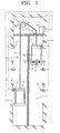
- Fig. 1 is a vertical cross sectional view that schematically shows the construction of an elevator apparatus according to a first embodiment of the present invention.
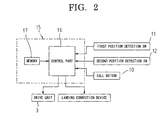
- Fig. 2 is a system diagram of the elevator apparatus according to the first embodiment of the present invention.
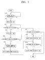
- Fig. 3 is a flow chart that explains the operation of the elevator apparatus according to the first embodiment of the present invention.
- a drive unit 3 and a deflector wheel 4 are installed in a machine room 2 which is constructed at an upper portion of a hoistway 1, with a main rope 5 being extended or wrapped around a sheave 3a of the drive unit 3 and the deflector wheel 4.
- a first car 6 is connected with a sheave-side end of the main rope 5
- a second car 7 is connected with a deflector wheel-side end of the main rope 5. Further, it is constructed such that when one of the first car 6 and the second car 7 lands on the top floor, the other car can land the bottom floor.
- the second car 7 has its chamber or cab 7a mounted on a car frame 7b for vertical movement relative thereto.
- a pantograph structure 8 is arranged between the floor of the cab 7a or the car frame 7b.
- a drive motor 9 for driving the pantograph structure 8 in the vertical movement is mounted on the car frame 7b.
- the pantograph structure 8 and the drive motor 9 together constitute a landing correction device.
- a call button 10 is installed in an elevator hall or landing place of each floor, and a first position detection switch 11 and a second position detection switch 12 are arranged on an inner wall surface of each floor in the hoistway 1. Also, a first position switch operation cam 13 and a second position switch operation cam 14 are arranged on the first car 6 and the second car 7, respectively. Upon landing of the first car 6 and the second car 7, the first position switch operation cam 13 and the second position switch operation cam 14 operate or actuate a first position detection switch 11 and a second position detection switch 12, respectively.
- the second position switch operation cam 14 is moved up and down in association with the vertical movement of the cab 7a with respect to the car frame 7b.
- the main control unit 15 is arranged in the machine room 2, and includes a control part 16 and a memory 17, as shown in Fig. 2.
- the main control unit 15 drives the first car 6 and the second car 7 to move in the vertical direction.
- the drive motor 9 is controlled to be driven to correct the landing position of the second car 7.
- the control part 16 writes the stop positions of the first and second cars 6, 7 into the memory 17 based on position signals for the first and second cars 6, 7 from the first and second position detection switches 11, 12.
- the stop positions of the first and second cars 6, 7 stored in the memory 17 are successively updated based on the position signals for the first and second cars 6, 7 from the first and second position detection switches 11, 12.
- control part 16 monitors car call signals from the call buttons 10 (step 100), so that when a call button 10 is pushed, the floor where a corresponding car call is generated is specified by the control part 16.
- a car near the car call generation floor is identified from the data of the stop positions of the first and second cars 6, 7 stored in the memory 17, and the drive unit 3 is driven so as to make the nearby car thus identified land on the car call generation floor (step 101).
- control part 16 determines, from the first position detection switch 13 on a set landing floor of the first car 6, whether the first car 6 has landed on the set landing floor (step 102). When it is determined that the first car 6 has normally landed on the set landing floor, the control part 16 stops the driving operation of the drive unit 3 (step 103).
- control part 16 performs arithmetic processing so as to determine, based on the data of floor-to-floor distances stored in the memory 17, whether it is necessary to correct the landing position of the second car 7 (step 104).
- step 104 determines that the correction of the landing position of the second car 7 is unnecessary
- the control flow moves to step 107, where it is determined, based on the second position detection switch 14 on a set landing floor of the second car 7, whether the second car 7 has landed on the set landing floor.
- the control part 16 opens the doors of the first and second cars 6, 7.
- step 107 when it is determined in step 107 that the second car 7 has not landed on the set landing floor, the control flow goes to step 108, where the drive motor 9 is driven to cause the pantograph structure 8 to move up or down, whereby the cab 7a of the second car 7 is moved in the vertical direction.
- the control part 16 determines, based on the second position detection switch 14 on the set landing floor of the second car 7, whether the second car 7 has landed on the set landing floor (step 109).
- step 110 the control part 16 stops the driving operation of the drive motor 9 (step 110).
- the doors of the first and second cars 6, 7 are opened.
- step 109 When it is determined in step 109 that the second car 7 has not landed on the set landing floor, a return to step 108 is performed.
- steps 108-110 together constitute a correction step or process for a landing deviation of the second car 7 resulting from a time-varying extension (i.e., extension over time) of the main rope 5 or an expansion or contraction of the main rope 5 due to the load acting thereon.
- step 104 when it is determined in step 104 that the correction of the landing position of the second car 7 is necessary, the control flow goes to step 105, where an amount of correction of the landing position of the second car 7 is calculated based on the data of floor-to-floor distances stored in the memory 17. Then, the drive motor 9 is driven to operate so that the amount of movement of the pantograph structure 8 is made equal to the amount of correction thus calculated (step 106), and thereafter the control flow goes to step 109.
- steps 104 through 106 together constitute a correction step or process for a landing deviation of the second car 7 resulting from a difference between floor-to-floor distances or an inequality in floor-to-floor distances.
- the landing correction device constructed from the pantograph structure 8 and the drive motor 9 is arranged on the second car 7, even if a landing deviation is generated in the second car 7 upon normal landing of the first car 6, the landing deviation of the second car 7 is quickly corrected by means of the landing correction device. Accordingly, the doors of the first and second cars 6, 7 can be made to open at the same time.
- the elevator apparatus according to this first embodiment adopts the 1:1 roping system, the structure thereof becomes simple, thus making it possible to reduce the cost of manufacture.
- the landing correction device is installed on the second car 7 alone, the number of landing correction devices used or required becomes one, and hence the reduction of cost can be accordingly made.
- control part 16 of the main control unit 15 controls the drive unit 3 in such a manner that the drive unit is driven to make the first car 6 normally land on its set landing floor, and the control part 16 also controls the pantograph structure 8 and the drive motor 9 so that they are driven to make the second car 7 normally land on its set landing floor. Therefore, even if there takes place a time-varying extension of the main rope 5 or an expansion or contraction thereof due to a load applied thereto, the first and second cars 6, 7 can be made to land on the respective floors substantially at the same time without generating any landing deviation, so that they can be opened at the same time.
- the floor-to-floor distances are stored in the memory 17, and the control part 16 calculates a landing deviation of the second car 7 generated upon normal landing of the first car 6, based on the data of the floor-to-floor distances stored in the memory 17, and controls to drive the pantograph structure 8 and the drive motor 9 so as to correct the calculated amount of landing deviation.
- the data of floor-to-floor distances stored in the memory 17 may be corrected based on the amount of correction of the landing deviation obtained in the process of correction of the landing deviation in steps 108 through 110.
- the data of floor-to-floor distances stored in the memory 17 is updated, so that the generation of a landing deviation of the second car 7 resulting from the expansion or contraction of the main rope 5 can be suppressed.
- Fig. 4 is a vertical cross sectional view that schematically shows the construction of an elevator apparatus according to a second embodiment according to the present invention.
- a second car 7A has a cab 7a fixed attached to a car frame 7b, and a landing correction device in the form of an electric winch 20 is arranged at a main rope connection portion of the second car 7A.
- the elevator apparatus operates based on the flow chart shown in Fig. 3.
- the control part 16 controls to drive the electric winch 20 so that the winch 20 winds up or draws out the main rope 5 thereby to correct the landing deviation of the second car 7A.
- the electric winch 20 is used as the landing correction device, and the electric winch 20 is arranged at the main rope connection portion of the second car 7A.
- the amount of correction of the second car 7A can be increased to accommodate a wide range of landing corrections, and the cab 7a need not be constructed such that it is movable in the vertical direction with respect to the car frame 7b, as in the above-mentioned first embodiment.
- the second car 7A can be of a simple structure. That is, a car of the same structure as that of the first car 6 can be used for the second car 7A.
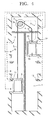
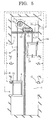
- Fig. 5 is a vertical cross sectional view that schematically shows the construction of an elevator apparatus according to a third embodiment according to the present invention.
- a fixed deflector wheel 21 is arranged in the machine room 2 at a location close to the deflector wheel 4 with its axis of rotation being in alignment or coincidence with the axis of rotation of the deflector wheel 4.
- a movable deflector wheel 22 is arranged in the machine room 2 with its axis of rotation being in parallel to the axis of rotation of the fixed deflector wheel 21 so as to be movable toward and away from the fixed deflector wheel 21.
- a movable deflector wheel driving part in the form of a hydraulic jack 23 is arranged in the machine room 2 so as to move the movable deflector wheel 22 toward or away from the fixed deflector wheel 21.
- the fixed deflector wheel 21, the movable deflector wheel 22 and the hydraulic jack 23 together constitute a landing correction device.
- the main rope 5 is connected with the first car 6, ascends therefrom so as to be wrapped around the sheave 3a, and further wrapped sequentially around the fixed deflector wheel 21, the movable deflector wheel 22 and the deflector wheel 4, and descends therefrom to be connected with the second car 7A.
- the fixed deflector wheel 21 and the movable deflector wheel 22 are arranged on the path of the main rope 5 between the sheave 3a and the deflector wheel 4.
- the elevator apparatus operates based on the flow chart shown in Fig. 3.
- the control part 16 controls the hydraulic jack 23 in such a manner that the hydraulic jack 23 is driven to move the movable deflector wheel 22 so as to approach or separate with respect to the deflector wheel 4 and the fixed deflector wheel 21, whereby the landing deviation of the second car 7A can be corrected.
- the second car 7A need not have a special structure, and the self weight of the second car 7A becomes lighter, thus making it possible to suppress the generation of the expansion and contraction of the main rope 5 due to the load applied thereto.
- the pair of the fixed deflector wheel 21 and the movable deflector wheel 22 are arranged on the path of the main rope between the sheave 3a and the deflector wheel 4, so roping ratio is increased, so a wide range of landing correction can be made with a small amount of movement of the movable deflector wheel 22.
- the number of pairs of the fixed deflector wheel 21 and the movable deflector wheel 22 is one, but a plurality of pairs of fixed deflector wheels 21 and movable deflector wheels 22 may instead be arranged on the main rope path between the sheave 3a and the deflector wheel 4. In this case, the roping ratio can be further increased, and hence it becomes possible to accommodate a much wider range of landing corrections.
- the movable deflector wheel drive part is not limited to such a hydraulic jack 23 but may instead comprise anything that is capable of moving the movable deflector wheel 22 to approach or separate with respect to the fixed deflector wheel 21.
- an electric motor and a mechanism for converting the rotating torque of this electric motor into a linear motion force may be used.
- the car connected with the sheave 3a side of the main rope 5 is made to normally land, and a landing deviation generated in the car connected with the deflector wheel 4 side of the main rope 5 is corrected, but the car connected with the deflector wheel side of the main rope 5 may instead be made to normally land, and a landing deviation generated in the car connected with the sheave side of the main rope 5 can be corrected.
- an elevator apparatus in which both cars connected with opposite ends of a main rope can be made to normally landed at the same time, is useful as an elevator apparatus capable of improving its service.
Landscapes
- Engineering & Computer Science (AREA)
- Automation & Control Theory (AREA)
- Computer Networks & Wireless Communication (AREA)
- Elevator Control (AREA)
- Lift-Guide Devices, And Elevator Ropes And Cables (AREA)
- Cage And Drive Apparatuses For Elevators (AREA)
Applications Claiming Priority (1)
| Application Number | Priority Date | Filing Date | Title |
|---|---|---|---|
| PCT/JP2002/011999 WO2004046007A1 (fr) | 2002-11-18 | 2002-11-18 | Dispositif d'elevateur |
Publications (3)
| Publication Number | Publication Date |
|---|---|
| EP1574467A1 true EP1574467A1 (fr) | 2005-09-14 |
| EP1574467A4 EP1574467A4 (fr) | 2010-09-01 |
| EP1574467B1 EP1574467B1 (fr) | 2012-08-29 |
Family
ID=32321484
Family Applications (1)
| Application Number | Title | Priority Date | Filing Date |
|---|---|---|---|
| EP02808158A Expired - Lifetime EP1574467B1 (fr) | 2002-11-18 | 2002-11-18 | Dispositif d'elevateur |
Country Status (5)
| Country | Link |
|---|---|
| EP (1) | EP1574467B1 (fr) |
| JP (1) | JPWO2004046007A1 (fr) |
| KR (1) | KR100685539B1 (fr) |
| CN (1) | CN100340464C (fr) |
| WO (1) | WO2004046007A1 (fr) |
Cited By (8)
| Publication number | Priority date | Publication date | Assignee | Title |
|---|---|---|---|---|
| EP2033925A1 (fr) * | 2007-08-29 | 2009-03-11 | Inventio Ag | Cabine d'ascenseur, ascenseur comprenant une telle cabine d'ascenseur et procédé pour la commande d'une cabine d'ascenseur |
| WO2009110907A1 (fr) * | 2008-03-07 | 2009-09-11 | Otis Elevator Company | Appareil de mise à niveau de cabine d’ascenseur secondaire |
| ITTV20110126A1 (it) * | 2011-09-22 | 2013-03-23 | Enalias S R L U | Sistema di movimentazione verticale e orizzontale della cabina di trasporto in un impianto eleva traslatore per il superamento di ostacoli |
| CN103449288A (zh) * | 2013-09-16 | 2013-12-18 | 罗湘林 | 一台曳引机驱动两台轿厢的节能电梯组 |
| WO2014068191A1 (fr) * | 2012-10-31 | 2014-05-08 | Kone Corporation | Agencement d'ascenseur |
| WO2014174353A1 (fr) | 2013-04-23 | 2014-10-30 | Scomparin Tarcisio | Système de déplacement vertical et horizontal |
| CN105060043A (zh) * | 2015-07-14 | 2015-11-18 | 日立电梯(中国)有限公司 | 一种使轿门地坎与层门地坎对齐的装置 |
| DE102019201184A1 (de) * | 2019-01-30 | 2020-07-30 | Thyssenkrupp Ag | Fahrkorb für eine Aufzugsanlage mit Linearmotorantrieb, Aufzugsanlage mit einem solchen Fahrkorb und Verfahren zum Betreiben einer Aufzugsanlage |
Families Citing this family (20)
| Publication number | Priority date | Publication date | Assignee | Title |
|---|---|---|---|---|
| JP4663388B2 (ja) * | 2005-04-22 | 2011-04-06 | 三菱電機株式会社 | エレベータ装置 |
| JP4502910B2 (ja) * | 2005-09-08 | 2010-07-14 | 株式会社Taiyo | エレベータ用の巻上げ装置およびケージの位置調整方法 |
| JP4848781B2 (ja) * | 2006-01-30 | 2011-12-28 | 三菱電機株式会社 | エレベータ装置 |
| CN101920885A (zh) * | 2010-08-27 | 2010-12-22 | 康力电梯股份有限公司 | 无对重双联电梯 |
| WO2012048748A1 (fr) * | 2010-10-14 | 2012-04-19 | Kone Corporation | Guides de rouleau extensible |
| JP5528997B2 (ja) * | 2010-12-09 | 2014-06-25 | 株式会社日立製作所 | エレベータのかご室振動低減装置 |
| JP5577275B2 (ja) * | 2011-02-17 | 2014-08-20 | 株式会社日立製作所 | 床高さ調節機構付きエレベーター |
| JP5607703B2 (ja) * | 2012-11-19 | 2014-10-15 | 東芝エレベータ株式会社 | エレベータ及びダブルデッキ型エレベータ |
| CN104909226B (zh) * | 2015-06-19 | 2016-09-14 | 成都信息工程大学 | 一种安全节能型双边式电梯及其使用方法 |
| CN105936461A (zh) * | 2016-06-08 | 2016-09-14 | 爱默生电梯有限公司 | 一种应用于较大人流量场合中的自平衡双联电梯 |
| CN105883552A (zh) * | 2016-06-28 | 2016-08-24 | 爱默生电梯有限公司 | 一种带弹簧踏板的电梯轿厢 |
| KR102135192B1 (ko) * | 2016-07-20 | 2020-07-17 | 미쓰비시덴키 가부시키가이샤 | 엘리베이터의 제어 장치 및 제어 방법 |
| DE102016217016A1 (de) * | 2016-09-07 | 2018-03-08 | Thyssenkrupp Ag | Fahrkorb für eine Aufzugsanlage mit Linearmotorantrieb, Aufzugsanlage mit einem solchen Fahrkorb und Verfahren zum Betreiben einer Aufzugsanlage |
| WO2018173146A1 (fr) * | 2017-03-22 | 2018-09-27 | 三菱電機株式会社 | Dispositif de commande d'ascenseur et procédé d'estimation de la quantité d'extension d'un câble de levage |
| JP2019043749A (ja) * | 2017-09-06 | 2019-03-22 | 株式会社日立製作所 | マルチカーエレベーター |
| WO2019063866A1 (fr) * | 2017-09-28 | 2019-04-04 | Kone Corporation | Procédé et système d'ascenseur permettant de définir un allongement d'un moyen de suspension de cabine d'ascenseur |
| WO2020003346A1 (fr) * | 2018-06-25 | 2020-01-02 | 三菱電機株式会社 | Système d'ascenseur |
| JP7097269B2 (ja) * | 2018-09-20 | 2022-07-07 | 株式会社日立製作所 | エレベータ制御システムおよび制御方法 |
| JP7328880B2 (ja) * | 2019-12-16 | 2023-08-17 | 株式会社日立製作所 | マルチカーエレベーター |
| CN114194984B (zh) * | 2022-01-26 | 2023-10-03 | 浙江西沃电梯有限公司 | 一种开门高度不一致的电梯开门结构 |
Family Cites Families (11)
| Publication number | Priority date | Publication date | Assignee | Title |
|---|---|---|---|---|
| JPS497663B1 (fr) * | 1969-10-23 | 1974-02-21 | ||
| JPS5633996B2 (fr) | 1974-02-22 | 1981-08-07 | ||
| JPS50114862U (fr) * | 1974-02-28 | 1975-09-19 | ||
| JPS52134960U (fr) * | 1976-04-08 | 1977-10-13 | ||
| JPS5580666A (en) * | 1978-12-14 | 1980-06-18 | Deirukusukoetsuteru Hodo | Auxiliary operation device for elevator |
| US4466510A (en) * | 1982-03-22 | 1984-08-21 | Staley Development Corporation | Automatic floor-leveling means for a cable-suspended elevator |
| CA1244783A (fr) * | 1984-08-13 | 1988-11-15 | Gordon A. Holland | Ascenseur a systeme d'isonivelage ameliore |
| JPS6460585A (en) * | 1987-08-31 | 1989-03-07 | Toshiba Corp | Position controller for elevator |
| JPH0266085A (ja) * | 1988-08-31 | 1990-03-06 | Toshiba Corp | エレベータのかご位置制御装置 |
| JPH0859106A (ja) * | 1994-08-18 | 1996-03-05 | Mitsubishi Denki Bill Techno Service Kk | エレベータの着床誤差修正装置 |
| JP2000118914A (ja) * | 1998-10-08 | 2000-04-25 | Hitachi Building Systems Co Ltd | エレベータ用主ロープの張力補正装置 |
-
2002
- 2002-11-18 KR KR1020047020367A patent/KR100685539B1/ko not_active Expired - Fee Related
- 2002-11-18 JP JP2004525645A patent/JPWO2004046007A1/ja active Pending
- 2002-11-18 EP EP02808158A patent/EP1574467B1/fr not_active Expired - Lifetime
- 2002-11-18 CN CNB028291603A patent/CN100340464C/zh not_active Expired - Fee Related
- 2002-11-18 WO PCT/JP2002/011999 patent/WO2004046007A1/fr not_active Ceased
Cited By (17)
| Publication number | Priority date | Publication date | Assignee | Title |
|---|---|---|---|---|
| EP2033925A1 (fr) * | 2007-08-29 | 2009-03-11 | Inventio Ag | Cabine d'ascenseur, ascenseur comprenant une telle cabine d'ascenseur et procédé pour la commande d'une cabine d'ascenseur |
| WO2009110907A1 (fr) * | 2008-03-07 | 2009-09-11 | Otis Elevator Company | Appareil de mise à niveau de cabine d’ascenseur secondaire |
| AU2012311213B2 (en) * | 2011-09-22 | 2017-02-23 | Pedarco International Limited | System of vertical and horizontal movement of the transport cabin in a elevator translator plant for the overcoming of obstacles |
| ITTV20110126A1 (it) * | 2011-09-22 | 2013-03-23 | Enalias S R L U | Sistema di movimentazione verticale e orizzontale della cabina di trasporto in un impianto eleva traslatore per il superamento di ostacoli |
| WO2013041941A1 (fr) * | 2011-09-22 | 2013-03-28 | Enalias S.R.L.U. | Système de déplacement vertical et horizontal de la cabine de transport dans un ascenseur-translateur pour surmonter les obstacles |
| KR20140081827A (ko) * | 2011-09-22 | 2014-07-01 | 페다코 인터내셔널 리미티드 | 장애물들의 극복을 위한 엘리베이터 변환기 플랜트에서의 수송 캐빈의 수직 및 수평 이동 시스템 |
| CN103987645A (zh) * | 2011-09-22 | 2014-08-13 | 必德高国际有限公司 | 克服障碍的升降机平移机设备中传送客厢的竖直和水平运动系统 |
| CN103987645B (zh) * | 2011-09-22 | 2017-05-03 | 必德高国际有限公司 | 克服障碍的升降机平移机设备中传送客厢的竖直和水平运动系统 |
| US9469506B2 (en) | 2011-09-22 | 2016-10-18 | Pedarco International Limited | System of vertical and horizontal movement of the transport cabin in a elevator translator plant for the overcoming of obstacles |
| US10399819B2 (en) | 2012-10-31 | 2019-09-03 | Kone Corporation | Elevator arrangement |
| WO2014068191A1 (fr) * | 2012-10-31 | 2014-05-08 | Kone Corporation | Agencement d'ascenseur |
| EP2914527A4 (fr) * | 2012-10-31 | 2016-07-06 | Kone Corp | Agencement d'ascenseur |
| WO2014174353A1 (fr) | 2013-04-23 | 2014-10-30 | Scomparin Tarcisio | Système de déplacement vertical et horizontal |
| CN103449288A (zh) * | 2013-09-16 | 2013-12-18 | 罗湘林 | 一台曳引机驱动两台轿厢的节能电梯组 |
| CN105060043B (zh) * | 2015-07-14 | 2017-03-29 | 日立电梯(中国)有限公司 | 一种使轿门地坎与层门地坎对齐的装置 |
| CN105060043A (zh) * | 2015-07-14 | 2015-11-18 | 日立电梯(中国)有限公司 | 一种使轿门地坎与层门地坎对齐的装置 |
| DE102019201184A1 (de) * | 2019-01-30 | 2020-07-30 | Thyssenkrupp Ag | Fahrkorb für eine Aufzugsanlage mit Linearmotorantrieb, Aufzugsanlage mit einem solchen Fahrkorb und Verfahren zum Betreiben einer Aufzugsanlage |
Also Published As
| Publication number | Publication date |
|---|---|
| KR20050004923A (ko) | 2005-01-12 |
| CN100340464C (zh) | 2007-10-03 |
| CN1628066A (zh) | 2005-06-15 |
| KR100685539B1 (ko) | 2007-02-22 |
| EP1574467B1 (fr) | 2012-08-29 |
| EP1574467A4 (fr) | 2010-09-01 |
| JPWO2004046007A1 (ja) | 2006-03-16 |
| WO2004046007A1 (fr) | 2004-06-03 |
Similar Documents
| Publication | Publication Date | Title |
|---|---|---|
| EP1574467B1 (fr) | Dispositif d'elevateur | |
| JP4457450B2 (ja) | ダブルデッキエレベータ制御装置 | |
| JPH09175748A (ja) | エレベータかご位置補償装置 | |
| CN102741145B (zh) | 双层升降机设施 | |
| US5220981A (en) | Elevator and a procedure for its control | |
| US9963321B2 (en) | Elevator device | |
| KR101400806B1 (ko) | 수직과 수평 및 경사 이동구간을 갖는 승강기 | |
| KR20040010778A (ko) | 더블 데크 엘리베이터 | |
| JP4260288B2 (ja) | ダブルデッキエレベータ | |
| JP2012162361A (ja) | ダブルデッキエレベータの診断装置 | |
| JP4919593B2 (ja) | エレベータの運転装置 | |
| JP6419638B2 (ja) | 両かごエレベーター | |
| KR100427463B1 (ko) | 더블덱 엘리베이터 | |
| JP4190910B2 (ja) | エレベータ及びその故障時運転方法 | |
| JP2017160008A (ja) | 工事用エレベータ | |
| JP2010208781A (ja) | エレベータ | |
| EP1319626A1 (fr) | Elevateur et methode d'inspection de celui-ci | |
| JP3905613B2 (ja) | エレベータ | |
| WO2004087552A1 (fr) | Appareil permettant de piloter un ascenseur a cabines superposees jusqu'a un niveau d'atterrissage | |
| JP2001019287A (ja) | 可動式ダブルデッキエレベータの制御装置 | |
| JP3953105B2 (ja) | 水平方向に移送されたエレベータかごを用いるエレベータシャトル | |
| JP2914832B2 (ja) | 自走式エレベータ | |
| JP6079323B2 (ja) | ダブルデッキエレベータの制御装置 | |
| JP6261459B2 (ja) | エレベータの制御装置およびエレベータの制御方法 | |
| JPH05286669A (ja) | ロープレスリニアモータエレベーター |
Legal Events
| Date | Code | Title | Description |
|---|---|---|---|
| PUAI | Public reference made under article 153(3) epc to a published international application that has entered the european phase |
Free format text: ORIGINAL CODE: 0009012 |
|
| 17P | Request for examination filed |
Effective date: 20041214 |
|
| AK | Designated contracting states |
Kind code of ref document: A1 Designated state(s): AT BE BG CH CY CZ DE DK EE ES FI FR GB GR IE IT LI LU MC NL PT SE SK TR |
|
| AX | Request for extension of the european patent |
Extension state: AL LT LV MK RO SI |
|
| DAX | Request for extension of the european patent (deleted) | ||
| RBV | Designated contracting states (corrected) |
Designated state(s): DE |
|
| RAP1 | Party data changed (applicant data changed or rights of an application transferred) |
Owner name: MITSUBISHI DENKI KABUSHIKI KAISHA |
|
| A4 | Supplementary search report drawn up and despatched |
Effective date: 20100729 |
|
| RIC1 | Information provided on ipc code assigned before grant |
Ipc: B66B 1/42 20060101AFI20040608BHEP Ipc: B66B 11/00 20060101ALI20100723BHEP |
|
| 17Q | First examination report despatched |
Effective date: 20110218 |
|
| GRAP | Despatch of communication of intention to grant a patent |
Free format text: ORIGINAL CODE: EPIDOSNIGR1 |
|
| GRAS | Grant fee paid |
Free format text: ORIGINAL CODE: EPIDOSNIGR3 |
|
| GRAA | (expected) grant |
Free format text: ORIGINAL CODE: 0009210 |
|
| AK | Designated contracting states |
Kind code of ref document: B1 Designated state(s): DE |
|
| REG | Reference to a national code |
Ref country code: DE Ref legal event code: R096 Ref document number: 60243622 Country of ref document: DE Effective date: 20121025 |
|
| PLBE | No opposition filed within time limit |
Free format text: ORIGINAL CODE: 0009261 |
|
| STAA | Information on the status of an ep patent application or granted ep patent |
Free format text: STATUS: NO OPPOSITION FILED WITHIN TIME LIMIT |
|
| 26N | No opposition filed |
Effective date: 20130530 |
|
| REG | Reference to a national code |
Ref country code: DE Ref legal event code: R097 Ref document number: 60243622 Country of ref document: DE Effective date: 20130530 |
|
| REG | Reference to a national code |
Ref country code: DE Ref legal event code: R084 Ref document number: 60243622 Country of ref document: DE |
|
| REG | Reference to a national code |
Ref country code: DE Ref legal event code: R084 Ref document number: 60243622 Country of ref document: DE Effective date: 20141107 |
|
| PGFP | Annual fee paid to national office [announced via postgrant information from national office to epo] |
Ref country code: DE Payment date: 20171114 Year of fee payment: 16 |
|
| REG | Reference to a national code |
Ref country code: DE Ref legal event code: R119 Ref document number: 60243622 Country of ref document: DE |
|
| PG25 | Lapsed in a contracting state [announced via postgrant information from national office to epo] |
Ref country code: DE Free format text: LAPSE BECAUSE OF NON-PAYMENT OF DUE FEES Effective date: 20190601 |