EP1559919A2 - Vorrichtung zur Erzeugung gedrosselter Blas- oder Saugluft - Google Patents
Vorrichtung zur Erzeugung gedrosselter Blas- oder Saugluft Download PDFInfo
- Publication number
- EP1559919A2 EP1559919A2 EP05100103A EP05100103A EP1559919A2 EP 1559919 A2 EP1559919 A2 EP 1559919A2 EP 05100103 A EP05100103 A EP 05100103A EP 05100103 A EP05100103 A EP 05100103A EP 1559919 A2 EP1559919 A2 EP 1559919A2
- Authority
- EP
- European Patent Office
- Prior art keywords
- throttle section
- throttle
- sheet
- projections
- section
- Prior art date
- Legal status (The legal status is an assumption and is not a legal conclusion. Google has not performed a legal analysis and makes no representation as to the accuracy of the status listed.)
- Granted
Links
- 238000007664 blowing Methods 0.000 title claims description 6
- 238000007639 printing Methods 0.000 claims description 14
- 238000001746 injection moulding Methods 0.000 claims description 5
- 238000004049 embossing Methods 0.000 claims description 4
- 239000000463 material Substances 0.000 claims description 4
- 238000000034 method Methods 0.000 claims description 4
- 125000006850 spacer group Chemical group 0.000 description 3
- 238000010276 construction Methods 0.000 description 2
- 238000004519 manufacturing process Methods 0.000 description 2
- 241000252254 Catostomidae Species 0.000 description 1
- 230000002349 favourable effect Effects 0.000 description 1
- 238000000926 separation method Methods 0.000 description 1
Images



Classifications
-
- F—MECHANICAL ENGINEERING; LIGHTING; HEATING; WEAPONS; BLASTING
- F15—FLUID-PRESSURE ACTUATORS; HYDRAULICS OR PNEUMATICS IN GENERAL
- F15D—FLUID DYNAMICS, i.e. METHODS OR MEANS FOR INFLUENCING THE FLOW OF GASES OR LIQUIDS
- F15D1/00—Influencing flow of fluids
- F15D1/0005—Baffle plates
Definitions
- the invention relates to a device for generating throttled blowing or Suction air, in which a pneumatic pressure generator at the beginning of a throttle section is connected, with blowing or suction air flows into the throttle section and through Turbulence in the throttle section throttled blowing or suction air at the end of Throttle valve on or flows out.
- throttle ranges are z. B. by WO 01/14752 A1.
- a throttle section is a number of webs and a plurality of each two adjacent chambers formed chambers provided, which alternately so are arranged opposite each other, that a web in each case a chamber opposite.
- the construction effort is large and costly.
- the invention is therefore an object of the invention to provide a simple alternative.
- the new throttle section a simple Structure has and can be produced inexpensively.
- she has one extremely good impermeability to the environment. It turned out to be perfect sufficiently exposed, if only one side of the throttle section protrusions and between these formed vortex chambers, whereas the projections opposite throttle wall can remain unprocessed.
- the Distance (gap) between the projections and the opposite choke wall in that a plate with openings in such a way between two Throttling path forming layers is arranged that the breakthrough in the field of the respective throttle section is arranged.
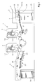
- a printing press has a feeder 2, at least one printing unit 3 or 4 and a boom 6.
- the bow 7 are from taken from a sheet stack 8 and isolated or scaly over a Feeding 9 fed to the printing units 3 and 4.
- These contain in a known manner in each case a plate cylinder 11; 12.
- the plate cylinders 11 and 12 each have one Device 13, 14 for attaching flexible printing plates.
- everyone is Plate cylinder 11; 12, a device 16; 17 for semi or fully automatic Assigned plate change.
- the sheet stack 8 rests on a controllably liftable stacking plate 10.
- the removal the sheet 7 takes place from the top of the sheet stack 8 by means of a so-called Suction head 18, which includes a number of lifting and Schleppsaugern 19, 21 for the separation of the sheet 7 has.
- the blowing devices 22 are for Loosening of the upper sheet layers and sensing elements 23 for stack tracking intended.
- a number of lateral and rear stops 24 are provided for aligning the sheet stack 8, in particular the upper sheet 7 of the Sheet stack 8, a number of lateral and rear stops 24 are provided.
- a bow guide 27 in Shape of a pneumatic sheet guiding element below a chain guide 28th arranged.
- the sheet guiding element 27 has at least one on its underside 30 Connection for a pressure generator, in particular blower 29, on.
- a pressure generator in particular blower 29, on.
- the device according to the invention is not limited to blown air, but is in the same size and unchanged with suction air applicable.
- a throttle section 33 is provided which between inlet and Outlet opening 36, 32 has a flow channel 34 having a number of Is provided swirling elements. These are on a wall 38 of the flow channel 34 spaced as projections 39 from each other in or against the flow direction arranged.
- a gap S formed, the flow of the Blow or suction guaranteed.
- vortex chambers 44 are formed, which cause a turbulence and thus the restrict the free flow of blown or suction air.
- the throttle section 33 consists essentially of two parts, namely the supporting guide 51 with Outflow opening 32 and a lower part 57 with inflow opening 36, which together forms with the Tragleitelement 51, the throttle section 33.
- the lower part 57 is made of a manufactured single component, which is preferably produced by injection molding, wherein the material may be a plastic.
- the embossing process is used, the zu used material may also be a plastic.
- the lower part 57 in this case has in each case the spaced-apart projections 39, each of which two adjacent projections 39 form a swirl chamber 44.
- the Flow channel 34 is defined by a throttle section 33 limiting paragraph 58th formed, which is pressed against the underside of the Tragleitiatas 51.
- the Inlet opening 36 is either directly to the blow-suction air source or together with the remaining inflow openings 36 by means of an antechamber 56 with the blow-suction air source 29 connected.
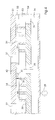
- Figures 5 to 7 show enlarged views of throttle lines, the injection molding or Embossing processes were produced.
- Figure 5 shows the already described parallel throttle section 34 with a constant passage gap s between the tips 41 of the projections 39 and the underside of the Tragleitides 51st
- FIG. 6 shows a throttle section 33 with a widening passage gap s.
- FIG. 7 shows a throttle section 33 which is adapted to a curved bearing guide element 51 is, for. B. for use on cylinders or rolls of printing presses.
Landscapes
- Engineering & Computer Science (AREA)
- Physics & Mathematics (AREA)
- Fluid Mechanics (AREA)
- Mechanical Engineering (AREA)
- General Engineering & Computer Science (AREA)
- Feeding Of Articles By Means Other Than Belts Or Rollers (AREA)
- Moulds For Moulding Plastics Or The Like (AREA)
- Supply, Installation And Extraction Of Printed Sheets Or Plates (AREA)
- Delivering By Means Of Belts And Rollers (AREA)
- Sheets, Magazines, And Separation Thereof (AREA)
- Jet Pumps And Other Pumps (AREA)
Abstract
Description
- Figur 1
- eine Bogenrotationsdruckmaschine in schematischer Darstellung im Schnitt,
- Figur 2
- ein Bogenleitelement im Bereich des Auslegers im Schnitt in schematischer Darstellung,
- Figur 3
- eine Draufsicht auf das Bogenleitelement in perspektivischer Ansicht,
- Figur 4
- einen Schnitt durch das Bogenleitelement mit einer Drosselstrecke im Lagenaufbau,
- Figur 5
- einen Schnitt durch ein alternatives Bogenleitelement, welches im Spritzguss- oder Prägeverfahren hergestellt wurde,
- Figur 6
- einen Schnitt durch eine Drosselstrecke gemäß Figur 5,
- Figur 7
- einen Schnitt durch eine alternative Drosselstrecke, und
- Figur 8
- einen Schnitt durch eine zweite alternative Drosselstrecke.
- 1
- Druckmaschine
- 2
- Anleger
- 3
- Druckwerk
- 4
- Druckwerk
- 5
- ./.
- 6
- Ausleger
- 7
- Bogen
- 7 a
- nächster Bogen
- 8
- Bogenstapel
- 9
- Zuführtisch
- 10
- Stapelplatte
- 11
- Plattenzylinder
- 12
- Plattenzylinder
- 13
- Druckplattenbefestigungseinrichtung
- 14
- Druckplattenbefestigungseinrichtung
- 15
- ./.
- 16
- Druckplattenwechsler
- 17
- Druckplattenwechsler
- 18
- Saugkopf
- 19
- Hubsauger
- 20
- ./.
- 21
- Schleppsauger
- 22
- Blaseinrichtung
- 23
- Tastelement
- 24
- Anschlag
- 25
- ./.
- 26
- Auslagestapel
- 27
- Bogenführung/Bogenleitelement
- 28
- Kettenführung
- 29
- Druck- bzw. Saugluft-Erzeuger (-Quelle)
- 30
- ./.
- 31
- Oberseite (27)
- 32
- Ausströmöffnung
- 33
- Drosselstrecke
- 34
- Strömungskanal
- 35
- ./.
- 36
- Einströmöffnung (57)
- 37
- ./.
- 38
- Wand
- 39
- Vorsprung
- 40
- ./.
- 41
- Spitzen (39)
- 42
- Wand
- 43
- Spalt
- 44
- Wirbelkammern
- 45 - 50
- ./.
- 51
- Tragleitelemente
- 52
- Abstandsplatte
- 53
- Drosselplatte
- 54
- Einströmplatte
- 55
- ./.
- 56
- Vorkammern
- 57
- Unterteil
- 58
- Absatz
- s
- Abstand 41-42
Claims (9)
- Vorrichtung zur Erzeugung gedrosselter Blas- oder Saugluft mit einer zwischen einem Einlass und einem Auslass angeordneten Drosselstrecke,
dadurch gekennzeichnet, dass die Drosselstrecke (33) einen Strömungskanal (34) aufweist, der auf einer Seite eine Anzahl voneinander beabstandete Vorsprünge (39) aufweist, wobei jeweils zwischen zwei Vorsprüngen (39, 39) eine Wirbelkammer (44) gebildet wird und wobei zwischen den Spitzen (41) der Vorsprünge (39) und der gegenüber liegenden Wand der Strömungskanal (34) gebildet ist. - Vorrichtung nach Anspruch 1,
dadurch gekennzeichnet, dass die Drosselstrecke (33) aus mehreren mit Durchbrüchen versehenen Lagen (51, 52, 53, 54) aufgebaut ist. - Vorrichtung nach Anspruch 1,
dadurch gekennzeichnet, dass die Drosselstrecke (33) im Wesentlichen aus zwei Teilen aufgebaut ist, wobei das die Drosselstrecke (33) charakterisierende Unterteil (57) im Spritzgussverfahren hergestellt ist. - Vorrichtung nach Anspruch 1,
dadurch gekennzeichnet, dass die Drosselstrecke (33) im Wesentlichen aus zwei Teilen aufgebaut ist, wobei das die Drosselstrecke (33) charakterisierende Unterteil (57) im Prägeverfahren hergestellt ist. - Vorrichtung nach Anspruch 3 oder 4,
dadurch gekennzeichnet, dass das Unterteil (57) aus einem Kunststoffmaterial hergestellt ist. - Vorrichtung nach einem der vorhergehenden Ansprüche ,
dadurch gekennzeichnet, dass eine Vorkammer (56) vorgesehen ist, um eine Mehrzahl von Drosselstrecken (33) gemeinsam mit einem Blas- oder Sauglufterzeuger (29) zu verbinden. - Vorrichtung nach einem der vorhergehenden Ansprüche,
dadurch gekennzeichnet, dass diese Vorrichtung in einem Bogenleitelement (27) in einer Bogen verarbeitenden Maschine vorgesehen ist. - Vorrichtung nach einem der vorhergehenden Ansprüche,
dadurch gekennzeichnet, dass das Bogenleitelement (27) im Bereich einer Kettenführung (28) zum Ausleger (6) angeordnet ist. - Vorrichtung nach einem der vorhergehenden Ansprüche,
dadurch gekennzeichnet, dass die Drosselstrecke (33) in Bogenleitelementen einer Bogenrotationsdruckmaschine verwendet wird.
Applications Claiming Priority (2)
| Application Number | Priority Date | Filing Date | Title |
|---|---|---|---|
| DE102004004396 | 2004-01-29 | ||
| DE102004004396A DE102004004396A1 (de) | 2004-01-29 | 2004-01-29 | Vorrichtung zur Erzeugung gedrosselter Blas- oder Saugluft |
Publications (3)
| Publication Number | Publication Date |
|---|---|
| EP1559919A2 true EP1559919A2 (de) | 2005-08-03 |
| EP1559919A3 EP1559919A3 (de) | 2010-06-09 |
| EP1559919B1 EP1559919B1 (de) | 2016-04-13 |
Family
ID=34638794
Family Applications (1)
| Application Number | Title | Priority Date | Filing Date |
|---|---|---|---|
| EP05100103.0A Expired - Lifetime EP1559919B1 (de) | 2004-01-29 | 2005-01-11 | Vorrichtung zur Erzeugung gedrosselter Blas- oder Saugluft |
Country Status (6)
| Country | Link |
|---|---|
| US (1) | US7384035B2 (de) |
| EP (1) | EP1559919B1 (de) |
| JP (1) | JP4921715B2 (de) |
| CN (1) | CN100560367C (de) |
| DE (1) | DE102004004396A1 (de) |
| HK (1) | HK1080129A1 (de) |
Families Citing this family (6)
| Publication number | Priority date | Publication date | Assignee | Title |
|---|---|---|---|---|
| JP4713397B2 (ja) * | 2006-01-18 | 2011-06-29 | 株式会社リコー | 微小流路構造体及び微小液滴生成システム |
| JP4619305B2 (ja) * | 2006-03-03 | 2011-01-26 | リョービ株式会社 | 搬送機構、搬送機構の制御方法および搬送方法 |
| DE102010023485A1 (de) * | 2009-07-09 | 2011-01-13 | Heidelberger Druckmaschinen Ag | Bogenführungstrommel |
| US8800753B2 (en) | 2009-09-10 | 2014-08-12 | Bdt Media Automation Gmbh | System for conveying an article using vortex suction units |
| DE102013010943B4 (de) * | 2012-07-26 | 2024-03-14 | Heidelberger Druckmaschinen Ag | Bogenleitvorrichtung |
| CN104229531B (zh) * | 2013-06-09 | 2017-10-24 | 征图新视(江苏)科技有限公司 | 格栅吸风装置 |
Citations (2)
| Publication number | Priority date | Publication date | Assignee | Title |
|---|---|---|---|---|
| WO2001014752A1 (en) | 1999-08-25 | 2001-03-01 | Core Flow Ltd. | Apparatus for inducing forces by fluid injection |
| DE10304618A1 (de) | 2002-03-25 | 2003-10-09 | Heidelberger Druckmasch Ag | Labyrinthdüse |
Family Cites Families (15)
| Publication number | Priority date | Publication date | Assignee | Title |
|---|---|---|---|---|
| US3514074A (en) * | 1968-05-06 | 1970-05-26 | Richard E Self | High energy loss fluid control |
| GB2128953B (en) * | 1982-10-28 | 1986-04-09 | Bishopbarn Ltd | Conveyor with suction means for holding articles in contact therewith |
| US4591140A (en) * | 1983-03-12 | 1986-05-27 | Agfa-Gevaert Aktiengesellschaft | Arrangement for separating and transporting uppermost sheets of a stack of sheets or sheet-like objects |
| US4850537A (en) * | 1986-12-08 | 1989-07-25 | Energy Innovations, Inc. | Method and apparatus for producing multivortex fluid flow |
| JPH069112A (ja) * | 1992-06-26 | 1994-01-18 | Seiko Epson Corp | 薄シートの位置決め方法 |
| DE4406844C2 (de) * | 1994-03-03 | 1997-05-07 | Koenig & Bauer Albert Ag | Vorrichtung zum Führen von frisch beschichteten Bogen |
| DE19926749B4 (de) * | 1999-06-11 | 2008-11-20 | Heidelberger Druckmaschinen Ag | Farbwerk für eine Druckmaschine |
| JP2001124377A (ja) * | 1999-10-26 | 2001-05-11 | Masuda Harmo:Kk | 換気設備 |
| DE10131607A1 (de) * | 2000-07-28 | 2002-02-07 | Heidelberger Druckmasch Ag | Ausleger einer flächige Bedruckstoffe verarbeitenden Maschine |
| DE10133633A1 (de) * | 2000-08-31 | 2002-03-14 | Heidelberger Druckmasch Ag | Leit-und Tragelemente mit gedrosselter Blasluft |
| DE10042888A1 (de) * | 2000-08-31 | 2002-03-14 | Heidelberger Druckmasch Ag | Bogenleiteinrichtung |
| DE10042887A1 (de) * | 2000-08-31 | 2002-03-14 | Heidelberger Druckmasch Ag | Maschine zur Verarbeitung von Bogen |
| US7107907B2 (en) | 2001-01-22 | 2006-09-19 | Goss International Americas, Inc. | Flow-restricted printing cylinder for a removable printing sleeve |
| US6543948B2 (en) * | 2001-02-09 | 2003-04-08 | Hewlett-Packard Company | Printer with vacuum platen having selectable active area |
| JP4954439B2 (ja) * | 2002-10-21 | 2012-06-13 | ハイデルベルガー ドルツクマシーネン アクチエンゲゼルシヤフト | 空気圧式の枚葉紙案内装置を備える枚葉紙処理機械 |
-
2004
- 2004-01-29 DE DE102004004396A patent/DE102004004396A1/de not_active Withdrawn
-
2005
- 2005-01-11 EP EP05100103.0A patent/EP1559919B1/de not_active Expired - Lifetime
- 2005-01-24 US US11/041,552 patent/US7384035B2/en not_active Expired - Fee Related
- 2005-01-27 JP JP2005020350A patent/JP4921715B2/ja not_active Expired - Fee Related
- 2005-01-27 CN CNB2005100058709A patent/CN100560367C/zh not_active Expired - Fee Related
-
2006
- 2006-01-04 HK HK06100149.4A patent/HK1080129A1/zh unknown
Patent Citations (2)
| Publication number | Priority date | Publication date | Assignee | Title |
|---|---|---|---|---|
| WO2001014752A1 (en) | 1999-08-25 | 2001-03-01 | Core Flow Ltd. | Apparatus for inducing forces by fluid injection |
| DE10304618A1 (de) | 2002-03-25 | 2003-10-09 | Heidelberger Druckmasch Ag | Labyrinthdüse |
Also Published As
| Publication number | Publication date |
|---|---|
| CN100560367C (zh) | 2009-11-18 |
| HK1080129A1 (zh) | 2006-04-21 |
| EP1559919A3 (de) | 2010-06-09 |
| CN1648469A (zh) | 2005-08-03 |
| JP2005213045A (ja) | 2005-08-11 |
| US20050167905A1 (en) | 2005-08-04 |
| EP1559919B1 (de) | 2016-04-13 |
| JP4921715B2 (ja) | 2012-04-25 |
| DE102004004396A1 (de) | 2005-08-11 |
| US7384035B2 (en) | 2008-06-10 |
Similar Documents
| Publication | Publication Date | Title |
|---|---|---|
| WO1995023755A2 (de) | Vorrichtung zum schwebenden führen von bogen oder bahnen | |
| EP3733572B1 (de) | Flächensauggreifer | |
| EP0748289A1 (de) | Blaskasten zum schwebenden führen von bogen oder bahnen | |
| EP1184173B1 (de) | Bogenleiteinrichtung | |
| EP1559919B1 (de) | Vorrichtung zur Erzeugung gedrosselter Blas- oder Saugluft | |
| WO1995023701A1 (de) | Vorrichtung zum führen von frisch beschichteten bogen | |
| DE102020124433A1 (de) | Anleger einer Bogen be- oder verarbeitende Maschine sowie Verfahren zur Unterstützung der Bogenvereinzelung in einem Anleger einer Bogen be- oder verarbeitende Maschine | |
| DE10304618B4 (de) | Labyrinthdüse | |
| DE102013010943A1 (de) | Bogenleitvorrichtung | |
| EP1184175B1 (de) | Bogentransportzylinder | |
| DE10057570B4 (de) | Leitvorrichtung einer flächige Bedruckstoffe verarbeitenden Maschine | |
| EP0607538A1 (de) | Druckmaschine mit bogenführender Fläche | |
| DE102012000952A1 (de) | Trockner mit integrierter Pudereinrichtung | |
| DE3907037A1 (de) | Vorrichtung zur bogenlaengenabfrage in einer bogen bearbeitenden maschine, insbesondere einer bogen-rotationsdruckmaschine | |
| DE102006002357A1 (de) | Vorrichtung zum Tragen oder Leiten eines Bedruckstoffbogens | |
| EP0386470A2 (de) | Vorrichtung zur Bogenlängenabfrage in einer Bogen bearbeitenden Maschine, insbesondere einer Bogen-Rotationsdruckmaschine | |
| DE4433644B4 (de) | Verfahren und Vorrichtung zur Führung eines Bogens | |
| DE102012215798B4 (de) | Flächensauggreifer | |
| DE10042887A1 (de) | Maschine zur Verarbeitung von Bogen | |
| DE10133633A1 (de) | Leit-und Tragelemente mit gedrosselter Blasluft | |
| DE10003024A1 (de) | Rütteltisch | |
| DE102009028738B4 (de) | Bogentransportvorrichtung in einer Verarbeitungsmaschine und Verfahren zum Führen von Bogenmaterial | |
| EP1698577B1 (de) | Saugbändertisch | |
| DE102010042928B4 (de) | Bogentransportvorrichtung in einer Verarbeitungsmaschine und Verfahren zum Führen von Bogenmaterial | |
| EP1221369A1 (de) | Bogenleiteinrichtung in Druckmaschinen |
Legal Events
| Date | Code | Title | Description |
|---|---|---|---|
| PUAI | Public reference made under article 153(3) epc to a published international application that has entered the european phase |
Free format text: ORIGINAL CODE: 0009012 |
|
| AK | Designated contracting states |
Kind code of ref document: A2 Designated state(s): AT BE BG CH CY CZ DE DK EE ES FI FR GB GR HU IE IS IT LI LT LU MC NL PL PT RO SE SI SK TR |
|
| AX | Request for extension of the european patent |
Extension state: AL BA HR LV MK YU |
|
| PUAL | Search report despatched |
Free format text: ORIGINAL CODE: 0009013 |
|
| AK | Designated contracting states |
Kind code of ref document: A3 Designated state(s): AT BE BG CH CY CZ DE DK EE ES FI FR GB GR HU IE IS IT LI LT LU MC NL PL PT RO SE SI SK TR |
|
| AX | Request for extension of the european patent |
Extension state: AL BA HR LV MK YU |
|
| 17P | Request for examination filed |
Effective date: 20101209 |
|
| AKX | Designation fees paid |
Designated state(s): AT BE BG CH CY CZ DE DK EE ES FI FR GB GR HU IE IS IT LI LT LU MC NL PL PT RO SE SI SK TR |
|
| 17Q | First examination report despatched |
Effective date: 20110202 |
|
| GRAP | Despatch of communication of intention to grant a patent |
Free format text: ORIGINAL CODE: EPIDOSNIGR1 |
|
| INTG | Intention to grant announced |
Effective date: 20151117 |
|
| GRAS | Grant fee paid |
Free format text: ORIGINAL CODE: EPIDOSNIGR3 |
|
| GRAA | (expected) grant |
Free format text: ORIGINAL CODE: 0009210 |
|
| AK | Designated contracting states |
Kind code of ref document: B1 Designated state(s): AT BE BG CH CY CZ DE DK EE ES FI FR GB GR HU IE IS IT LI LT LU MC NL PL PT RO SE SI SK TR |
|
| REG | Reference to a national code |
Ref country code: GB Ref legal event code: FG4D Free format text: NOT ENGLISH |
|
| REG | Reference to a national code |
Ref country code: AT Ref legal event code: REF Ref document number: 790483 Country of ref document: AT Kind code of ref document: T Effective date: 20160415 Ref country code: CH Ref legal event code: EP |
|
| REG | Reference to a national code |
Ref country code: DE Ref legal event code: R081 Ref document number: 502005015183 Country of ref document: DE Owner name: HEIDELBERGER DRUCKMASCHINEN AG, DE Free format text: FORMER OWNER: HEIDELBERGER DRUCKMASCHINEN AG, 69115 HEIDELBERG, DE |
|
| REG | Reference to a national code |
Ref country code: IE Ref legal event code: FG4D Free format text: LANGUAGE OF EP DOCUMENT: GERMAN |
|
| REG | Reference to a national code |
Ref country code: DE Ref legal event code: R096 Ref document number: 502005015183 Country of ref document: DE |
|
| REG | Reference to a national code |
Ref country code: LT Ref legal event code: MG4D |
|
| REG | Reference to a national code |
Ref country code: NL Ref legal event code: MP Effective date: 20160413 |
|
| PG25 | Lapsed in a contracting state [announced via postgrant information from national office to epo] |
Ref country code: PL Free format text: LAPSE BECAUSE OF FAILURE TO SUBMIT A TRANSLATION OF THE DESCRIPTION OR TO PAY THE FEE WITHIN THE PRESCRIBED TIME-LIMIT Effective date: 20160413 Ref country code: FI Free format text: LAPSE BECAUSE OF FAILURE TO SUBMIT A TRANSLATION OF THE DESCRIPTION OR TO PAY THE FEE WITHIN THE PRESCRIBED TIME-LIMIT Effective date: 20160413 Ref country code: NL Free format text: LAPSE BECAUSE OF FAILURE TO SUBMIT A TRANSLATION OF THE DESCRIPTION OR TO PAY THE FEE WITHIN THE PRESCRIBED TIME-LIMIT Effective date: 20160413 Ref country code: LT Free format text: LAPSE BECAUSE OF FAILURE TO SUBMIT A TRANSLATION OF THE DESCRIPTION OR TO PAY THE FEE WITHIN THE PRESCRIBED TIME-LIMIT Effective date: 20160413 |
|
| PG25 | Lapsed in a contracting state [announced via postgrant information from national office to epo] |
Ref country code: PT Free format text: LAPSE BECAUSE OF FAILURE TO SUBMIT A TRANSLATION OF THE DESCRIPTION OR TO PAY THE FEE WITHIN THE PRESCRIBED TIME-LIMIT Effective date: 20160816 Ref country code: SE Free format text: LAPSE BECAUSE OF FAILURE TO SUBMIT A TRANSLATION OF THE DESCRIPTION OR TO PAY THE FEE WITHIN THE PRESCRIBED TIME-LIMIT Effective date: 20160413 Ref country code: GR Free format text: LAPSE BECAUSE OF FAILURE TO SUBMIT A TRANSLATION OF THE DESCRIPTION OR TO PAY THE FEE WITHIN THE PRESCRIBED TIME-LIMIT Effective date: 20160714 Ref country code: ES Free format text: LAPSE BECAUSE OF FAILURE TO SUBMIT A TRANSLATION OF THE DESCRIPTION OR TO PAY THE FEE WITHIN THE PRESCRIBED TIME-LIMIT Effective date: 20160413 |
|
| PG25 | Lapsed in a contracting state [announced via postgrant information from national office to epo] |
Ref country code: IT Free format text: LAPSE BECAUSE OF FAILURE TO SUBMIT A TRANSLATION OF THE DESCRIPTION OR TO PAY THE FEE WITHIN THE PRESCRIBED TIME-LIMIT Effective date: 20160413 |
|
| REG | Reference to a national code |
Ref country code: DE Ref legal event code: R097 Ref document number: 502005015183 Country of ref document: DE |
|
| REG | Reference to a national code |
Ref country code: DE Ref legal event code: R081 Ref document number: 502005015183 Country of ref document: DE Owner name: HEIDELBERGER DRUCKMASCHINEN AG, DE Free format text: FORMER OWNER: HEIDELBERGER DRUCKMASCHINEN AKTIENGESELLSCHAFT, 69115 HEIDELBERG, DE |
|
| PG25 | Lapsed in a contracting state [announced via postgrant information from national office to epo] |
Ref country code: RO Free format text: LAPSE BECAUSE OF FAILURE TO SUBMIT A TRANSLATION OF THE DESCRIPTION OR TO PAY THE FEE WITHIN THE PRESCRIBED TIME-LIMIT Effective date: 20160413 Ref country code: SK Free format text: LAPSE BECAUSE OF FAILURE TO SUBMIT A TRANSLATION OF THE DESCRIPTION OR TO PAY THE FEE WITHIN THE PRESCRIBED TIME-LIMIT Effective date: 20160413 Ref country code: EE Free format text: LAPSE BECAUSE OF FAILURE TO SUBMIT A TRANSLATION OF THE DESCRIPTION OR TO PAY THE FEE WITHIN THE PRESCRIBED TIME-LIMIT Effective date: 20160413 Ref country code: DK Free format text: LAPSE BECAUSE OF FAILURE TO SUBMIT A TRANSLATION OF THE DESCRIPTION OR TO PAY THE FEE WITHIN THE PRESCRIBED TIME-LIMIT Effective date: 20160413 Ref country code: CZ Free format text: LAPSE BECAUSE OF FAILURE TO SUBMIT A TRANSLATION OF THE DESCRIPTION OR TO PAY THE FEE WITHIN THE PRESCRIBED TIME-LIMIT Effective date: 20160413 |
|
| PLBE | No opposition filed within time limit |
Free format text: ORIGINAL CODE: 0009261 |
|
| STAA | Information on the status of an ep patent application or granted ep patent |
Free format text: STATUS: NO OPPOSITION FILED WITHIN TIME LIMIT |
|
| 26N | No opposition filed |
Effective date: 20170116 |
|
| PG25 | Lapsed in a contracting state [announced via postgrant information from national office to epo] |
Ref country code: SI Free format text: LAPSE BECAUSE OF FAILURE TO SUBMIT A TRANSLATION OF THE DESCRIPTION OR TO PAY THE FEE WITHIN THE PRESCRIBED TIME-LIMIT Effective date: 20160413 Ref country code: BE Free format text: LAPSE BECAUSE OF NON-PAYMENT OF DUE FEES Effective date: 20170131 |
|
| REG | Reference to a national code |
Ref country code: CH Ref legal event code: PL |
|
| GBPC | Gb: european patent ceased through non-payment of renewal fee |
Effective date: 20170111 |
|
| PG25 | Lapsed in a contracting state [announced via postgrant information from national office to epo] |
Ref country code: MC Free format text: LAPSE BECAUSE OF FAILURE TO SUBMIT A TRANSLATION OF THE DESCRIPTION OR TO PAY THE FEE WITHIN THE PRESCRIBED TIME-LIMIT Effective date: 20160413 |
|
| REG | Reference to a national code |
Ref country code: FR Ref legal event code: ST Effective date: 20170929 |
|
| PG25 | Lapsed in a contracting state [announced via postgrant information from national office to epo] |
Ref country code: LI Free format text: LAPSE BECAUSE OF NON-PAYMENT OF DUE FEES Effective date: 20170131 Ref country code: FR Free format text: LAPSE BECAUSE OF NON-PAYMENT OF DUE FEES Effective date: 20170131 Ref country code: CH Free format text: LAPSE BECAUSE OF NON-PAYMENT OF DUE FEES Effective date: 20170131 |
|
| REG | Reference to a national code |
Ref country code: IE Ref legal event code: MM4A |
|
| PG25 | Lapsed in a contracting state [announced via postgrant information from national office to epo] |
Ref country code: GB Free format text: LAPSE BECAUSE OF NON-PAYMENT OF DUE FEES Effective date: 20170111 Ref country code: LU Free format text: LAPSE BECAUSE OF NON-PAYMENT OF DUE FEES Effective date: 20170111 |
|
| REG | Reference to a national code |
Ref country code: BE Ref legal event code: MM Effective date: 20170131 |
|
| PG25 | Lapsed in a contracting state [announced via postgrant information from national office to epo] |
Ref country code: IE Free format text: LAPSE BECAUSE OF NON-PAYMENT OF DUE FEES Effective date: 20170111 |
|
| REG | Reference to a national code |
Ref country code: AT Ref legal event code: MM01 Ref document number: 790483 Country of ref document: AT Kind code of ref document: T Effective date: 20170111 |
|
| PG25 | Lapsed in a contracting state [announced via postgrant information from national office to epo] |
Ref country code: AT Free format text: LAPSE BECAUSE OF NON-PAYMENT OF DUE FEES Effective date: 20170111 |
|
| PGFP | Annual fee paid to national office [announced via postgrant information from national office to epo] |
Ref country code: DE Payment date: 20190131 Year of fee payment: 15 |
|
| PG25 | Lapsed in a contracting state [announced via postgrant information from national office to epo] |
Ref country code: HU Free format text: LAPSE BECAUSE OF FAILURE TO SUBMIT A TRANSLATION OF THE DESCRIPTION OR TO PAY THE FEE WITHIN THE PRESCRIBED TIME-LIMIT; INVALID AB INITIO Effective date: 20050111 |
|
| PG25 | Lapsed in a contracting state [announced via postgrant information from national office to epo] |
Ref country code: BG Free format text: LAPSE BECAUSE OF FAILURE TO SUBMIT A TRANSLATION OF THE DESCRIPTION OR TO PAY THE FEE WITHIN THE PRESCRIBED TIME-LIMIT Effective date: 20160413 |
|
| PG25 | Lapsed in a contracting state [announced via postgrant information from national office to epo] |
Ref country code: CY Free format text: LAPSE BECAUSE OF NON-PAYMENT OF DUE FEES Effective date: 20160413 |
|
| PG25 | Lapsed in a contracting state [announced via postgrant information from national office to epo] |
Ref country code: TR Free format text: LAPSE BECAUSE OF FAILURE TO SUBMIT A TRANSLATION OF THE DESCRIPTION OR TO PAY THE FEE WITHIN THE PRESCRIBED TIME-LIMIT Effective date: 20160413 |
|
| PG25 | Lapsed in a contracting state [announced via postgrant information from national office to epo] |
Ref country code: IS Free format text: LAPSE BECAUSE OF FAILURE TO SUBMIT A TRANSLATION OF THE DESCRIPTION OR TO PAY THE FEE WITHIN THE PRESCRIBED TIME-LIMIT Effective date: 20160813 |
|
| REG | Reference to a national code |
Ref country code: DE Ref legal event code: R119 Ref document number: 502005015183 Country of ref document: DE |
|
| PG25 | Lapsed in a contracting state [announced via postgrant information from national office to epo] |
Ref country code: DE Free format text: LAPSE BECAUSE OF NON-PAYMENT OF DUE FEES Effective date: 20200801 |