EP1553774B1 - Inhaltsempfangsvorrichtung und inhaltssendevorrichtung - Google Patents
Inhaltsempfangsvorrichtung und inhaltssendevorrichtung Download PDFInfo
- Publication number
- EP1553774B1 EP1553774B1 EP03741425.7A EP03741425A EP1553774B1 EP 1553774 B1 EP1553774 B1 EP 1553774B1 EP 03741425 A EP03741425 A EP 03741425A EP 1553774 B1 EP1553774 B1 EP 1553774B1
- Authority
- EP
- European Patent Office
- Prior art keywords
- packet
- content
- super
- capsule
- super capsule
- Prior art date
- Legal status (The legal status is an assumption and is not a legal conclusion. Google has not performed a legal analysis and makes no representation as to the accuracy of the status listed.)
- Expired - Lifetime
Links
- 239000002775 capsule Substances 0.000 claims description 150
- 238000004891 communication Methods 0.000 claims description 53
- 230000005540 biological transmission Effects 0.000 claims description 28
- 238000012545 processing Methods 0.000 description 25
- 238000000034 method Methods 0.000 description 24
- 239000000872 buffer Substances 0.000 description 12
- 238000013467 fragmentation Methods 0.000 description 12
- 238000006062 fragmentation reaction Methods 0.000 description 12
- 238000007906 compression Methods 0.000 description 10
- 230000006835 compression Effects 0.000 description 10
- 230000007704 transition Effects 0.000 description 8
- 230000008569 process Effects 0.000 description 7
- 238000010586 diagram Methods 0.000 description 6
- 238000005538 encapsulation Methods 0.000 description 6
- 238000003672 processing method Methods 0.000 description 6
- 239000012536 storage buffer Substances 0.000 description 5
- 230000001360 synchronised effect Effects 0.000 description 4
- 230000003111 delayed effect Effects 0.000 description 3
- 230000006870 function Effects 0.000 description 3
- 238000012546 transfer Methods 0.000 description 3
- 239000000969 carrier Substances 0.000 description 2
- 238000012790 confirmation Methods 0.000 description 2
- 238000012217 deletion Methods 0.000 description 2
- 230000037430 deletion Effects 0.000 description 2
- 230000000694 effects Effects 0.000 description 2
- 230000008030 elimination Effects 0.000 description 2
- 238000003379 elimination reaction Methods 0.000 description 2
- 229920001690 polydopamine Polymers 0.000 description 2
- 238000002360 preparation method Methods 0.000 description 2
- 230000005236 sound signal Effects 0.000 description 2
- 239000007853 buffer solution Substances 0.000 description 1
- 230000003139 buffering effect Effects 0.000 description 1
- 230000008859 change Effects 0.000 description 1
- 238000013144 data compression Methods 0.000 description 1
- 230000001419 dependent effect Effects 0.000 description 1
- 238000009432 framing Methods 0.000 description 1
- 238000003780 insertion Methods 0.000 description 1
- 230000037431 insertion Effects 0.000 description 1
- 238000007726 management method Methods 0.000 description 1
- 230000007246 mechanism Effects 0.000 description 1
- 238000012544 monitoring process Methods 0.000 description 1
- 238000011084 recovery Methods 0.000 description 1
- 230000004044 response Effects 0.000 description 1
- 239000004065 semiconductor Substances 0.000 description 1
- 238000000547 structure data Methods 0.000 description 1
- 230000000007 visual effect Effects 0.000 description 1
Images


Classifications
-
- H—ELECTRICITY
- H04—ELECTRIC COMMUNICATION TECHNIQUE
- H04N—PICTORIAL COMMUNICATION, e.g. TELEVISION
- H04N7/00—Television systems
- H04N7/16—Analogue secrecy systems; Analogue subscription systems
- H04N7/173—Analogue secrecy systems; Analogue subscription systems with two-way working, e.g. subscriber sending a programme selection signal
- H04N7/17345—Control of the passage of the selected programme
-
- H—ELECTRICITY
- H04—ELECTRIC COMMUNICATION TECHNIQUE
- H04L—TRANSMISSION OF DIGITAL INFORMATION, e.g. TELEGRAPHIC COMMUNICATION
- H04L1/00—Arrangements for detecting or preventing errors in the information received
- H04L1/12—Arrangements for detecting or preventing errors in the information received by using return channel
- H04L1/16—Arrangements for detecting or preventing errors in the information received by using return channel in which the return channel carries supervisory signals, e.g. repetition request signals
- H04L1/1607—Details of the supervisory signal
- H04L1/1671—Details of the supervisory signal the supervisory signal being transmitted together with control information
- H04L1/1678—Details of the supervisory signal the supervisory signal being transmitted together with control information where the control information is for timing, e.g. time stamps
-
- H—ELECTRICITY
- H04—ELECTRIC COMMUNICATION TECHNIQUE
- H04L—TRANSMISSION OF DIGITAL INFORMATION, e.g. TELEGRAPHIC COMMUNICATION
- H04L1/00—Arrangements for detecting or preventing errors in the information received
- H04L1/12—Arrangements for detecting or preventing errors in the information received by using return channel
- H04L1/16—Arrangements for detecting or preventing errors in the information received by using return channel in which the return channel carries supervisory signals, e.g. repetition request signals
- H04L1/18—Automatic repetition systems, e.g. Van Duuren systems
-
- H—ELECTRICITY
- H04—ELECTRIC COMMUNICATION TECHNIQUE
- H04N—PICTORIAL COMMUNICATION, e.g. TELEVISION
- H04N21/00—Selective content distribution, e.g. interactive television or video on demand [VOD]
- H04N21/20—Servers specifically adapted for the distribution of content, e.g. VOD servers; Operations thereof
- H04N21/23—Processing of content or additional data; Elementary server operations; Server middleware
- H04N21/235—Processing of additional data, e.g. scrambling of additional data or processing content descriptors
-
- H—ELECTRICITY
- H04—ELECTRIC COMMUNICATION TECHNIQUE
- H04N—PICTORIAL COMMUNICATION, e.g. TELEVISION
- H04N21/00—Selective content distribution, e.g. interactive television or video on demand [VOD]
- H04N21/20—Servers specifically adapted for the distribution of content, e.g. VOD servers; Operations thereof
- H04N21/23—Processing of content or additional data; Elementary server operations; Server middleware
- H04N21/236—Assembling of a multiplex stream, e.g. transport stream, by combining a video stream with other content or additional data, e.g. inserting a URL [Uniform Resource Locator] into a video stream, multiplexing software data into a video stream; Remultiplexing of multiplex streams; Insertion of stuffing bits into the multiplex stream, e.g. to obtain a constant bit-rate; Assembling of a packetised elementary stream
- H04N21/23614—Multiplexing of additional data and video streams
-
- H—ELECTRICITY
- H04—ELECTRIC COMMUNICATION TECHNIQUE
- H04N—PICTORIAL COMMUNICATION, e.g. TELEVISION
- H04N21/00—Selective content distribution, e.g. interactive television or video on demand [VOD]
- H04N21/20—Servers specifically adapted for the distribution of content, e.g. VOD servers; Operations thereof
- H04N21/23—Processing of content or additional data; Elementary server operations; Server middleware
- H04N21/238—Interfacing the downstream path of the transmission network, e.g. adapting the transmission rate of a video stream to network bandwidth; Processing of multiplex streams
- H04N21/2381—Adapting the multiplex stream to a specific network, e.g. an Internet Protocol [IP] network
-
- H—ELECTRICITY
- H04—ELECTRIC COMMUNICATION TECHNIQUE
- H04N—PICTORIAL COMMUNICATION, e.g. TELEVISION
- H04N21/00—Selective content distribution, e.g. interactive television or video on demand [VOD]
- H04N21/20—Servers specifically adapted for the distribution of content, e.g. VOD servers; Operations thereof
- H04N21/23—Processing of content or additional data; Elementary server operations; Server middleware
- H04N21/238—Interfacing the downstream path of the transmission network, e.g. adapting the transmission rate of a video stream to network bandwidth; Processing of multiplex streams
- H04N21/2389—Multiplex stream processing, e.g. multiplex stream encrypting
- H04N21/23895—Multiplex stream processing, e.g. multiplex stream encrypting involving multiplex stream encryption
-
- H—ELECTRICITY
- H04—ELECTRIC COMMUNICATION TECHNIQUE
- H04N—PICTORIAL COMMUNICATION, e.g. TELEVISION
- H04N21/00—Selective content distribution, e.g. interactive television or video on demand [VOD]
- H04N21/40—Client devices specifically adapted for the reception of or interaction with content, e.g. set-top-box [STB]; Operations thereof
- H04N21/43—Processing of content or additional data, e.g. demultiplexing additional data from a digital video stream; Elementary client operations, e.g. monitoring of home network or synchronising decoder's clock; Client middleware
- H04N21/435—Processing of additional data, e.g. decrypting of additional data, reconstructing software from modules extracted from the transport stream
-
- H—ELECTRICITY
- H04—ELECTRIC COMMUNICATION TECHNIQUE
- H04N—PICTORIAL COMMUNICATION, e.g. TELEVISION
- H04N21/00—Selective content distribution, e.g. interactive television or video on demand [VOD]
- H04N21/60—Network structure or processes for video distribution between server and client or between remote clients; Control signalling between clients, server and network components; Transmission of management data between server and client, e.g. sending from server to client commands for recording incoming content stream; Communication details between server and client
- H04N21/61—Network physical structure; Signal processing
- H04N21/6106—Network physical structure; Signal processing specially adapted to the downstream path of the transmission network
- H04N21/6125—Network physical structure; Signal processing specially adapted to the downstream path of the transmission network involving transmission via Internet
-
- H—ELECTRICITY
- H04—ELECTRIC COMMUNICATION TECHNIQUE
- H04N—PICTORIAL COMMUNICATION, e.g. TELEVISION
- H04N21/00—Selective content distribution, e.g. interactive television or video on demand [VOD]
- H04N21/60—Network structure or processes for video distribution between server and client or between remote clients; Control signalling between clients, server and network components; Transmission of management data between server and client, e.g. sending from server to client commands for recording incoming content stream; Communication details between server and client
- H04N21/63—Control signaling related to video distribution between client, server and network components; Network processes for video distribution between server and clients or between remote clients, e.g. transmitting basic layer and enhancement layers over different transmission paths, setting up a peer-to-peer communication via Internet between remote STB's; Communication protocols; Addressing
- H04N21/637—Control signals issued by the client directed to the server or network components
- H04N21/6375—Control signals issued by the client directed to the server or network components for requesting retransmission, e.g. of data packets lost or corrupted during transmission from server
-
- H—ELECTRICITY
- H04—ELECTRIC COMMUNICATION TECHNIQUE
- H04N—PICTORIAL COMMUNICATION, e.g. TELEVISION
- H04N21/00—Selective content distribution, e.g. interactive television or video on demand [VOD]
- H04N21/60—Network structure or processes for video distribution between server and client or between remote clients; Control signalling between clients, server and network components; Transmission of management data between server and client, e.g. sending from server to client commands for recording incoming content stream; Communication details between server and client
- H04N21/63—Control signaling related to video distribution between client, server and network components; Network processes for video distribution between server and clients or between remote clients, e.g. transmitting basic layer and enhancement layers over different transmission paths, setting up a peer-to-peer communication via Internet between remote STB's; Communication protocols; Addressing
- H04N21/643—Communication protocols
- H04N21/64322—IP
-
- H—ELECTRICITY
- H04—ELECTRIC COMMUNICATION TECHNIQUE
- H04N—PICTORIAL COMMUNICATION, e.g. TELEVISION
- H04N21/00—Selective content distribution, e.g. interactive television or video on demand [VOD]
- H04N21/60—Network structure or processes for video distribution between server and client or between remote clients; Control signalling between clients, server and network components; Transmission of management data between server and client, e.g. sending from server to client commands for recording incoming content stream; Communication details between server and client
- H04N21/63—Control signaling related to video distribution between client, server and network components; Network processes for video distribution between server and clients or between remote clients, e.g. transmitting basic layer and enhancement layers over different transmission paths, setting up a peer-to-peer communication via Internet between remote STB's; Communication protocols; Addressing
- H04N21/643—Communication protocols
- H04N21/6437—Real-time Transport Protocol [RTP]
-
- H—ELECTRICITY
- H04—ELECTRIC COMMUNICATION TECHNIQUE
- H04N—PICTORIAL COMMUNICATION, e.g. TELEVISION
- H04N21/00—Selective content distribution, e.g. interactive television or video on demand [VOD]
- H04N21/80—Generation or processing of content or additional data by content creator independently of the distribution process; Content per se
- H04N21/85—Assembly of content; Generation of multimedia applications
- H04N21/854—Content authoring
- H04N21/8547—Content authoring involving timestamps for synchronizing content
-
- H—ELECTRICITY
- H04—ELECTRIC COMMUNICATION TECHNIQUE
- H04N—PICTORIAL COMMUNICATION, e.g. TELEVISION
- H04N7/00—Television systems
- H04N7/16—Analogue secrecy systems; Analogue subscription systems
- H04N7/173—Analogue secrecy systems; Analogue subscription systems with two-way working, e.g. subscriber sending a programme selection signal
- H04N7/17309—Transmission or handling of upstream communications
- H04N7/17318—Direct or substantially direct transmission and handling of requests
Definitions
- the present invention relates to Content receivers and Content transmitters.
- transmitters and receivers that have functions including streaming for transmitting and receiving images, sound, and content through communications networks are becoming popular on the market.
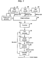
- FIG. 7 shows a structure of the conventional content transmitter.
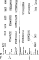
- Fig. 10 shows a transition of a packet structure in conventional content transmitters and content receivers.
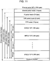
- Fig. 11 shows the conventional packet structure.
- Video encoder 51 in Fig. 7 encodes video signals using a predetermined compression format, and outputs encoded signals to the next step.
- Fig. 7 shows the case of using the MPEG2 format.
- the output from video encoder 51 is composed of the MPEG2 transport stream packet (MPEG2-TSP).
- System clock generator 54 generates a 27-MHz clock signal.
- Video encoder 51 uses this 27-MHz clock as a system clock for encoding video signals.
- Audio encoder 52 encodes audio signals using the same compression format as video encoder 51, and outputs MPEG2-TSP signals to the next step.
- Data encoder 53 encodes data broadcasting and EPG data using the same compression format as video encoder 51, and outputs MPEG2-TSP signals to the next step.
- Stream multiplexer 55 multiplexes the above three types of MPEG2-TSP signals on a time base.
- Stream multiplexer 55 also generates a PCR signal that reproduces the system clock on the receiving side by periodically using the count of the system clock at a cycle of about 50 ms.
- This stream multiplexer 55 further multiplexes the above multiplexed signals after encoding PCR signals to MPEG2-TSP, and outputs an MPEG2 transport stream (MPEG2-TS) signals to the next step (this output signal is S11 in Fig. 10 ).
- Fig. 10 shows a transition of packet multiplexing on the time base.
- the abscissa is time. Any stationary delay in each processing is ignored, and thus are not indicated in Fig. 10 .
- VIDE01, VIDEO2, VIDEO3, AUDIO1, AUDIO2, and DATA1 in S11 are packets multiplexed by stream multiplexer 55.
- VIDEO1, VIDEO2, and VIDEO3 in S11 are video-encoded MPEG2-TSPs.
- AUDIO1 and AUDIO2 in S11 are audio-encoded MPEG2-TSPs.
- DATA1 in S11 is data-encoded MPEG2-TSP.
- the PCR signal is a known fact in the MPEG2 system, and thus its description is omitted here.
- Scrambler 56 encrypts MPEG2-TS using a predetermined encryption method, and outputs an encrypted signal.
- An example of the MULTI2 method is shown in the description.
- RTP packetizer 58 encapsulates one or more individual MPEG2-TSPs.
- RTP packetizer 58 has a counter which counts the bus clock reproduced based on reference time information provided to transmitter receiver 61 from a communications network. Transmitter receiver 61 is described later.
- RTP packetizer 58 then adds a header containing a time stamp which is the count and information for identifying that encapsulated information is MPEG2-TSP to the output signal. This output signal is S12 in Fig. 10 .
- RTP of S12 is the header. The time stamp is used for correcting jitter using the bus clock when a packet arrives at the receiving side.
- UDP/IP packetizer 59 stores each RTP packet in an IP datagram for transmitting each RTP packet over the IP communications network. UDP-IP packetizer 59 then adds an IP packet header to each of the stored RTP packets, and outputs them as IP packets. This output signal is S13 in Fig. 10 .
- the IP of S13 is a header such as the IP header in the communications protocol.
- the IP packet header is a known fact in Internet protocol, and thus its description is omitted here.
- Ethernet packetizer 60 stores the IP packet in the Ethernet data region, adds an Ethernet packet header and checksum, and then outputs it as the Ethernet packet.
- the Ethernet packet header and checksum are known facts in Internet protocol, and thus their description is omitted here.
- Transmitter receiver 61 transmits the Ethernet packet to the Internet network, and receives the aforementioned reference time information.
- Fig. 11 shows the structure of a conventional packet.
- ten MPEG2-TSPs are encapsulated, and an 8-byte header containing information for identifying MPEG2-TSP and a time stamp to be used at the packet arrival is added to create a 1892-byte RTP packet.
- an 8-byte UDP packet header is added to this RTP packet to create a 1900-byte UDP packet.
- a 24-byte IP packet header is added to the UDP packet to create a 1924-byte IP packet.
- a 14-byte Ethernet header and 4-byte checksum are added to this IP packet to create a 1942 Ethernet packet.
- MTU the maximum transmission unit
- the packet is split when the size of the packet data to be transmitted exceeds MTU. This type of processing is called fragmentation in the Internet field.
- MTU on the Ethernet communications network is 1500 bytes. Fragmentation on the communications network is not preventable because the data size of the data region in Ethernet packets exceeds MTU. Therefore, a packet which has lost its header information exists in some cases, but packet loss or jitter is difficult to compensate for after fragmentation at the receiving side.
- Fig. 8 shows a conventional configuration of a content receiver.
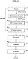
- Fig. 9 is a flowchart illustrating the operation of receiving and decoding a packet.
- Receiver 71 receives an Ethernet packet from a communications network such as the Internet, and outputs the packet to the next step.
- Fig. 11 shows this Ethernet packet.
- Ethernet packet processor 72 executes Ethernet protocol processing on the Ethernet packet given to Ethernet packet processor 72, and outputs an UDP/IP packet to the next step.
- STEP 91 in Fig. 9 shows this processing
- S14 in Fig. 10 shows the output signal.
- S14 in Fig. 10 shows that jitter and packet loss has occurred in a received UDP/IP packet as a result of transmission and receiving of the received UDP/IP packet via the Internet.
- a delay greater than a stationary delay has occurred in a packet containing VIDEO1 and DATA1.
- a delay smaller than a stationary delay has occurred in a packet containing VIDEO3 and AUDIO2.
- jitter and packet loss on the Internet are described with reference to Fig. 10 .
- a stationary delay exists between the transmitting and receiving sides on the Internet. Ideally, all packets are transmitted with this stationary delay. In this case, no jitter or packet loss occurs.
- jitter or packet loss occurs due to packets being allocated different routes, deletion of the packet in the gateway because of the inability to transmit the packet within a packet valid time, re-transmission of the packet, and so on.
- the stationary delay is intentionally not indicated in S14 to help understanding of jitter on a limited space. More specifically, a delay greater than the stationary delay occurs in the packet containing VIDE01 and DATA1, and thus S14 is more delayed (later) than S13 in the indication. Delay of the packet containing VIDEO3 and AUDIO2 is smaller than the stationary delay, and thus this packet is more advanced (faster) than S13 in the indication.
- UDP/IP packet processor 73 shown in Fig. 8 executes UDP/IP protocol processing on the UDP/IP packet, and outputs RTP packet.
- STEP 2 in Fig. 9 shows this processing.
- S15 in Fig. 10 shows this output signal.
- Ethernet and UDP/IP protocol processing mentioned above are a known fact in Internet protocol, and thus their description is omitted here.
- These communications protocols contain, in their header, information on how to process data protocols.
- Each protocol processing method is standardized, and the content receiver is likely to possess the applicable processing method in advance. Accordingly, the content receiver can process the data protocol after deleting the header by analyzing information on the protocol in the header.
- RTP packet processor 79 obtains the header of each RTP packet from each RTP packet shown in Fig. 11 .
- RTP packet processor 79 also obtains information on structure data included in the header. This information on data contents is information for identifying a format of data stored. Here, this information identifies that the data is aforementioned MPEG2-TSP.
- RTP packet processor 79 also has a counter for counting a bus clock reproduced based on the reference time information in receiver 71. RTP packet processor 79 counts this bus clock, and outputs MPEG2-TSP to the next step (Step 93 in Fig. 9 ) after removing the header when a count matches the time stamp in the header. RTP packet processor 79 then confirms whether MPEG2-TSP is scrambled (Step 94 in Fig. 9 ).
- the MPEG2-TSP header has information on whether MPEG2-TSP is scrambled in an area outside of the scrambled area. Accordingly, descrambling is applicable after taking out MPEG2-TSP and confirming the information.
- a predetermined method is applicable by determining in advance which method to use at the receiving and transmitting sides, or confirming and recognizing table information received on the receiving side.
- Descrambler 74 descrambles and outputs MPEG2-TSP in accordance with a method corresponding to the scrambling method determined at the transmitting side.
- Step 96 in Fig. 9 shows this process.
- S17 in Fig. 10 shows this output signal.
- TS decoder 77 adjusts MPEG2-TSP to a form to which AV decoder 78 can execute AV decoding (Step 97 in Fig. 9 ).
- AV decoder 78 executes AV decoding on data input to AV decoder 78, and outputs decoded data (Step 98 in Fig. 9 ).
- STEP 93 in Fig. 9 if the bus clock count and the time stamp in the header do not match, TS decoder 77 verifies their difference (STEP 95 in Fig. 9 ). If the difference is within a range that can be compensated by a buffer in the reproduction controller (not illustrated), TS decoder 77 stands by an extended TS packet in this buffer. If the difference exceeds the range that can be compensated by the buffer, TS decoder 77 controls to dispose of the applicable TS packet (Step 96 in Fig. 9 ).
- the RTP time stamp for jitter compensation is generated by counting the bus clock which is not related to encoding or decoding of the content.
- the reference time information used for generating the bus clock has insufficient accuracy relative to the jitter accuracy required during decoding. Still more, this reference time information is affected by jitter on the communications network. These cause insufficient accuracy in jitter compensation during decoding on the receiving side in some cases, generating a decoding error. This is the second technical problem which could be reformulated as "how to compensate for jitter occurring on a communications network".
- US 5,822,317 A describes a sender apparatus in a packet multiplexing transmission apparatus for packetizing lengthy information supplied from a plurality of information channels for multiplex transmission.
- Each packet is affixed with a time stamp for establishing synchronization in operation between the sender and a receiver.
- packets are generated and then affixed with the respective time stamps in order to make constant a delay time which intervenes between the affixation of the time stamp to the packet and the send-out thereof onto a network.
- JP 11 308203 A specifies how to obtain a simple signal receiver that receives a packet signal including time information added to absorb network jitter and time information added to reproduce a clock so as to recover the clock without affecting the network jitter.
- a program clock reference(PCR) extracted by an MPEG 2 TS de-multiplexer is corrected from difference information between a value indicated by a cycle timer at a time point when a source packet header elimination/time stamp extract device transfers data to the post-stage MPEG 2 TS de-multiplexer and a time stamp extracted by the source packet header elimination/time stamp extract device.
- EP 0 987 894 A2 describes in a real-time audio/visual system in which A/V data is conveyed over a jitter-introducing network, de-jittering and clock recovery processes can be achieved without requiring a Phase Locked Loop (PLL).
- PLL Phase Locked Loop
- audio/video streams are encoded into transport packets before being sent out.
- the dejittering process is achieved by a de-jittering buffer using the embedded timestamps in the transport packets and a client decoding clock. The delay variations of data arriving are removed after the client buffering process.
- each data packet is shifted to a synchronizing buffer and then fed to the A/V decoder according to the speed of A/V stream.
- the clock synchronization between client and server is achieved by a synchronizing buffer whose half-size position is taken as the reference.
- the drift rate of clock un-synchronization between client and server can be derived and, therefore, the client's clock can be adjusted to synchronize with the server's clock based on the derived drift.
- EP 1 091 583 A1 specifies a transport stream is received and recorded, and the recorded transport stream is reproduced normally.
- a cycle timer generates a time stamp based on a clock generated by means of a clock generation circuit that is independent of the system clock generated by means of a built-in PLL of an AV decoder, a receiver adds the time stamp to a TS packet, and the TS packet is recorded on a hard disk.
- a transmitter supplies the TS packet read out from the hard disk to the AV decoder by way of a switch, MPEG link integrated circuit, de-multiplexer, and FIFO memory at a timing so that the time interval between adjacent TS packets is coincident with that of the time when it was received based on the time stamp added to the TS packet
- WO 02/29991 A1 describes a group packet encapsulation and optionally compression system and method, including an encapsulation protocol increases packet transmission performance between two gateways or host computers by reducing data-link layer framing overhead, reducing packet routing overhead in gateways, compressing packet headers in the encapsulation packet, and increasing loss-less data compression ratio beyond that otherwise achievable in typical systems.
- Packets queued at a node configured in accordance with the present invention are classified, grouped, and encapsulated into a single packet as a function of having another such configured node in their path.
- the nodes exchange encapsulation packets, even though the packets within the encapsulation packet may ultimately have different destinations. Compression within an encapsulation packet may be performed on headers, payloads, or both.
- JP 2002 0340018 A describes how to provide a packet processor, a packet processing method, and a storage medium capable of recording digital data in a conventional storage medium without providing any special mechanism in the storage medium, and protecting a copyright by the limitation and encipherment of reproducing equipment.
- Time information outputted in a prescribed cycle is added to an inputted packet, and the packet to which the time information is added is enciphered and stored, and the stored packet to which the time information is added is read and decoded as necessary, and the decoded packet is outputted while the timing is controlled based on the time information added to the packet and the time information outputted in the prescribed cycle.
- JP 2001 045056 A describes how to improve the transmission efficiency while realizing compensation of code errors and delay fluctuations.
- a time stamp imparting circuit of a transmission station imparts a time stamp value to a received packet.
- a control information generating circuit generates control information denoting a packet input state by each time stamp value.
- a reception state management table of a reception station stores information on the basis of presence of packet reception by each time stamp value and received control information.
- a re-transmission information generating circuit generates re-transmission request information of a packet that is not received.
- a packet transmission control circuit 6 of the transmission station re-transmits the packet according to the re-transmission request information. In the case of having received a packet with a time stamp value matching with a 2nd time resulting from shifting a current time by a prescribed time, an output control circuit outputs this packet.
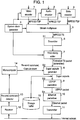
- Fig. 1 shows a configuration of a content transmitter in a first exemplary embodiment.
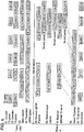
- Fig. 5 shows a transition of a packet structure of the content transmitter and a content receiver in the first exemplary embodiment.
- Fig. 6 shows the packet structure in the first exemplary embodiment.
- microcomputer 14 controls each part of the content transmitter.
- Video encoder 1 encodes signals using a predetermined compression format, and outputs an encoded video signal to the next step.
- the first exemplary embodiment describes an example of the MPEG2 format.
- the output from encoder 1 is composed of MPEG2-TSP.
- System clock generator 4 generates a 27 MHz clock signal.
- Video encoder 1 uses this 27-MHz clock as a system clock for encoding video signals.
- Audio encoder 2 encodes audio signals using the same compression format as video encoder 1, and outputs MPEG2-TSP signals to the next step.
- Data encoder 3 encodes data such as data broadcasting and EPG data using the same compression format as video encoder 1, and outputs MPEG2-TSP signals to the next step.
- Stream multiplexer 4 multiplexes the above three types of MPEG2-TSP on a time base. Stream multiplexer 4 also generates a PCR signal that reproduces the system clock on the receiving side periodically, using a counter for counting the system clock.
- the PCR signal is generated at a cycle of about 50 ms.
- Stream multiplexer 4 further multiplexes the PCR signal into the aforementioned multiplexed signal, after encoding the PCR signal to MPEG2-TSP, and outputs an MPEG2-TS.
- S1 in Fig. 5 shows this output signal.
- Fig. 5 shows a transition of packet multiplexing on the time base.
- the abscissa is time. Any stationary delay in each processing is ignored and thus not indicated in Fig. 5 .
- VIDEO1, VIDEO2, VIDEO3, AUDIO1, AUDIO2, and DATA1 in S5 are packets multiplexed by stream multiplexer 5.
- VIDEO1, VIDEO2, and VIDEO3 in S1 are video-encoded MPEG2-TSPs.
- AUDIO1 and AUDIO 2 in S1 are audio-encoded MPEG2-TSPs.
- DATA1 in S1 is data-encoded MPEG2-TSP.
- the PCR signal is a known fact in the MPEG2 system, and thus its description is omitted here.
- Scrambler 6 encrypts MPEG2-TS using a predetermined encryption method, and outputs an encrypted signal.
- the first exemplary embodiment shows an example of the MULTI2 method.
- Time stamp adder 7 has a second counter for counting the system clock output from system clock generator 4, and includes this count in a header as the time stamp. The time stamp adder then adds this header to each MPEG2-TS (scrambled in this exemplary embodiment), and outputs it to the next step as an extended TSP packet.
- S2 in Fig. 5 shows this output signal
- TS in Fig. 5 shows the header containing this time stamp.
- this time stamp is not used for obtaining the system clock.
- the receiving party ignores the packet generation timing at the transmitting party, and stores the packet in a storage device. The receiving party then uses this time stamp for obtaining the packet generation timing at the transmitting party (for reproducing MPEG2-TS) when reproducing the stored packet.
- This counter and a counter for generating the PCR signal are synchronized, since they use the same system clock.
- this counter is not synchronized with a counter in the receiving party in some cases. Accordingly, the frequency of the system clock, the maximum speed of the extended TS packet to be sent, and the minimum size of storage device 32 in the receiving party, which is described later, are predetermined so as to secure the time for reproduction at the receiving party. A bit number of this counter is set in a way such that all extended TS packets to be sent can be stored within the time that the counter goes around. In an example where all extended TS packets comprising the content are first stored in the receiving party and then reproduced, such as in the first exemplary embodiment, sufficient capacity for the storage device is secured, and thus no problem occurs with insufficient reproduction time at the receiving party.
- the counter On adding the time stamp, the counter is initialized at predetermined timing corresponding to the count of the PCR signal, and then time-stamped to synchronize the counter time-wise with the count used for generating the PCR signal. Or, this counter is initialized after a predetermined offset time, and then time-stamped. This allows the counter for reproducing the system clock using PCR at the receiving party also to be used as a counter for reproducing MPEG2-TS.
- the counter of the receiving party and this counter can be synchronized. In this case, it is preferable to match the bit number of this counter and the bit number of the counter for generating the PCR signal. Carry-over processing at the receiving party can thus be simplified.
- Super capsule generator 8 encapsulates one or more of individual extended TS packets.
- the header containing information for identifying that encapsulated information is the extended TS packet, the length of extended TS packet in the capsule, the number of extended TS packets, and the capsule count is added to the output signal, and output to the next step as a super capsule.
- S3 in Fig. 5 shows this super capsule.
- CH in Fig. 5 shows the header. This capsule count is used for confirming the continuity of super capsules at the receiving party.
- the super capsule generator 8 increments the count of this capsule counter every time the super capsule is output from super capsule generator 8.
- Fig. 5 two extended TS packets are encapsulated, but this is just for illustrative purposes.
- the first exemplary embodiment does not limit the number of extended TS packets.
- Information in the header added to the super capsule is designed to store the information for confirming the content of encapsulated data and the continuity of capsules at the receiving party, and thus the form of information is not limited to the aforementioned style.
- a capsule count can be included in information on the number of extended TS packets as the count of the extended TS packet.
- the length of an extended TS packet and the number of extended TS packets can be the total encapsulated data length.
- Super capsule generator 8 outputs the super capsule to the next step and also to storage buffer 5.
- Microcomputer 14 controls storage to storage buffer 15 using a ring buffer system. Microcomputer 14 manages a region for storing the super capsule in storage buffer 15 and the header information in each super capsule.
- Re-send command detector 13 detects a re-send command output from receiver 12. On controlling re-transmission of a super capsule, re-send command detector 13 outputs information for designating a super capsule which requires to be re-sent in the re-send command (at least a capsule count in this embodiment) and information for instructing re-transmission to microcomputer 14.
- Microcomputer 14 reads out a super capsule corresponding to the capsule count from storage buffer 15, and then controls the output of UDP/IP packetizer 9 for re-transmitting the super capsule.
- re-send information is further added to the header of the super capsule and then output.
- the counting range of the capsule counter is preferably the number of bits that can cover at least twice the maximum delay time on a communications network to be sent (delay until receiving the re-send command after transmitting the super capsule) in proportion to the transmission speed of the super capsule.
- the storage buffer size is preferably a capacity that can at least store the volume of super capsule equivalent to the counting range of the capsule counter. Any format for the re-send command previously determined with the receiving party is applicable, and thus the re-send command format is not particularly specified in this exemplary embodiment.
- UDP/IP packetizer 9 stores each super capsule in an IP datagram for sending each capsule to an IP communications network, and adds an IP packet header to output the capsule as an IP packet.
- S4 in Fig. 5 shows this output signal.
- IP in S4 is a header in a communications protocol such as an IP header.
- the IP packet header is a known fact in the Internet field, and thus its description is omitted here.
- the IP packet header is stored in the UDP packet, but this is not fundamentally required. Other protocols, such as storing the IP packet header in the TCP packet, are also applicable.
- Ethernet packetizer 10 stores the IP packet input in Ethernet packetizer 10 in the Ethernet data region. Ethernet packetizer 10 also adds an Ethernet packet header and checksum to the IP packet, and outputs the packet as an Ethernet packet.
- the Ethernet packet header and checksum are known facts in the Internet field, and thus their description is omitted here.
- Transmitter 11 transmits the Ethernet packet to the Internet network.
- Different common carriers administer communications networks in various methods on the Internet network, and transmitter 11 and receiver 12 support these different methods. Modes and specifications are not particularly limited.
- Fig. 6 shows the Ethernet packet structure in this exemplary embodiment.
- seven extended TS packets each of which made up of MPEG2-TSP and 4-byte headers, including time stamp, are encapsulated.
- an 8-byte header containing an identification value for identifying the extended TS packets, capsule counts, extended TS packet size, and the number of extended TS packets is added to form a 1352-byte super capsule.
- an 8-byte UDP packet header is further added to the super capsule to form a 1360 byte UDP packet.
- a 24-byte IP packet header is added to the UDP packet to make a 1384 byte IP packet.
- a 14-byte Ethernet header and 4-byte checksum are added to the IP packet to complete a 1402 byte Ethernet packet.
- the maximum transmission packet unit In the communications network, MTU, the maximum transmission packet unit, is often limited. When the size of packet data to be sent exceeds MTU, the packet is often split on the communications network. In the Internet field, this processing is called fragmentation. Compensation for packet loss and jitter which have occurred after fragmentation is difficult at the receiving party because header information is lost. Accordingly, in the first exemplary embodiment, the number of extended TS packets in the super capsule is set to seven capsules to prevent the data size of the Ethernet packet data region exceeding MTU 1500 bytes on the Ethernet communications network.
- the data size of MPEG2-TSP is fixed at 188 bytes in accordance with the specification of the encoder.
- the data size of the extended TS packet thus becomes 192 bytes. This means that the maximum number of extended transport packets that can be stored in the super capsule and also falls within MTU1500 bytes on the Ethernet communications network is seven packets.
- the setting of the number of extended TS packets in the super capsule in accordance with MTU on the communications network prevents fragmentation on the communications network. Furthermore, the addition of the aforementioned capsule count and the provision of the re-send function allow compensation for the packet loss at the receiving party.
- Communications networks are not limited to Internet using Ethernet connections.
- USB and wireless communications networks such as mobile phones are also supported.
- the MTU is also adjustable to values that suit these communications networks.
- the compression format is also not limited to MPEG2. For example, MPEG4 and other formats are acceptable.
- FIG. 2 shows the configuration of the content receiver in the first exemplary embodiment.
- Fig. 3 is a flowchart illustrating the operation from receiving and storing each packet.
- Fig. 4 is a flowchart illustrating reproduction after storing the packet.
- microcomputer 29 controls each part of the content receiver.
- Receiver 21 receives and outputs an Ethernet packet shown in Fig. 6 from a communications network such as the Internet network.
- a communications network such as the Internet network.
- a wide range of common carriers administer communications networks in various methods on the Internet network; and receiver 21 and transmitter31, described later, support these methods. Modes and specifications of these networks are not particularly limited.
- the communications network is not limited to Internet connections. USB and wireless communication networks, such as mobile phones, are also supported.
- Ethernet packet processor 22 executes Ethernet protocol processing on the Ethernet packet given to Ethernet packet processor 22, and outputs an UDP/IP packet (STEP 51 in Fig. 3 shows this processing, and S5 in Fig. 5 shows this output signal).
- S5 in Fig. 5 indicates that jitter and packet loss have occurred as a result of receiving the UDP/IP packet via the Internet.
- a delay greater than a stationary delay has occurred in a packet containing VIDEO 1 and DATA1.
- a delay smaller than a stationary delay has occurred in a packet containing VIDEO3 and AUDIO 2.
- a packet containing VIDEO2 and AUDIO1 has once become a packet loss, and re-sent.
- jitter and packet loss on the Internet are described next with reference to Fig. 5 .
- a stationary delay exists between the transmitting and receiving parties on the Internet network. Ideally, all packets are transmitted with this stationary delay. In this case, no jitter or packet loss occurs. However, in the Internet in practice, jitter or packet loss occurs due to a packet being allocated different routes, deletion of the packet at the gateway because of the inability to transmit the packet within a packet valid time, or re-transmission of the packet.
- a stationary delay is intentionally not indicated in S5 to help understanding of jitter on a limited space. More specifically, a delay greater than the stationary delay occurs in a packet containing VIDEO1 and DATA1, and thus this packet is indicated slower (looks more delayed) than S4.
- a delay smaller than the stationary delay occurs in the packet containing VIDEO3 and AUDIO2, and thus this packet is faster (looks more advanced) than S4.
- the packet containing VIDEO2 and AUDIO1 represents a packet loss, and then re-transmitted.
- UDP/IP packet processor 23 in Fig. 2 executes UDP/IP protocol processing on the UDP/IP packet, and outputs a super capsule (STEP 52 in Fig. 3 shows this processing, and S6 in Fig. 5 shows this output signal.)
- Ethernet and UDP/IP protocol processing are known facts in the Internet field, and thus their description is omitted here. Processing of the Ethernet packet and UDP packet is not limited to the way described in this exemplary embodiment. Other forms of protocol processing are executed in accordance with the type of a packet received and specifications of each communications network. Other communications protocol processing is also applicable.
- Protocol processing methods are standardized, and the content receiver can be provided with the applicable processing method in advance. Accordingly, the content receiver can process the data protocol after deleting the header by analyzing information on the protocol in the header.
- Capsule processor 24 obtains the header of each super capsule from each super capsule shown in Fig. 6 . Capsule processor 24 also outputs information on the data content structure included in this header to microcomputer 29.
- This information on the data content is information that identifies the format type of encapsulated data (in this example, information for identifying that the data is an extended TS packet).
- the information on this data content also includes the length of the extended TS packet in the capsule and the number of extended TS packets. Information providing the length of extended TS packet and the number of extended TS packets can also be the total length of encapsulated data.
- Microcomputer 29 interprets given information on data content, and recognizes that the encapsulated data is an extended TS packet (Step 53 in Fig. 3 ). Microcomputer 29 also recognizes the size of each extended TS packet, and secures a storage region in storage device 32. Microcomputer 29 also begins preparation, including the setting of storage packet size and address initialization setting for storing each extended TS packet, in storage controller 28 (Step 50 in Fig. 3 ). These preparations can also be implemented when the first super capsule is input or when information on data content is changed.
- Capsule processor 24 also monitors the capsule counter in the header for confirming continuity (Step 54 in Fig. 3 ). Capsule processor 24 detects the capsule count in each super capsule to check for a break in continuity. If capsule processor 24 detects a break in continuity, discontinuity is verified through a change in the capsule counter (Step 64 in Fig. 3 ).
- capsule processor 24 deletes super capsules detected after the discontinuity until a capsule count larger than the capsule count immediately before the discontinuity starts is found so as to solve the discontinuity (Step 65 in Fig. 3 ).
- capsule processor 24 does not delete super capsules which contain such discontinuity. Instead, capsule processor 24 notifies microcomputer 29 that it has detected a break in continuity, and outputs to microcomputer 29 the capsule count of applicable super capsules which have not been received.
- capsule processor 24 also generates a dummy super capsule consisting of a dummy extended TS packet provided with a dummy header. Capsule processor 24 then inserts this dummy super capsule in a time space that would otherwise have been occupied by the missing super capsule, and outputs it to the next step (Step 66 in Fig. 3 ). This simplifies the insertion of a re-sent packet in a later step.
- microcomputer 29 generates the re-send command using a capsule count of the applicable super capsule which capsule processor 24 could not have received (Step 67 in Fig. 3 ).
- Transmitter 31 transmits the re-send command to the transmitting party through a communications network such as the Internet network via Ethernet.
- the super capsule re-sent from the transmitting party includes information on re-transmission in its header, and thus this capsule can be detected at capsule processor 24. Accordingly, capsule processor 24 excludes this capsule from verifying discontinuity, and outputs the capsule untouched to the next step (Step 54 in Fig. 3 ).
- Microcomputer 29 does not need to control the transmission of the re-send command immediately after receiving notification on discontinuity from capsule processor 24.
- Microcomputer 29 controls the transmission of the re-send command if an applicable super capsule is not received within a predetermined time after instructing capsule processor 24 to stand by to receive the super capsule which has not been detected. If the applicable super capsule is received within a predetermined time after instructing standby for reception, capsule processor 24 adds information indicating a re-sent packet to an applicable header and outputs it to the next step. This is to apply the same processing as to the re-sent packet in later steps.
- the standby time should preferably be set shorter than the time that the count completes one cycle, and longer than the maximum delay time for packet arrival on the communications network. Confirmation of discontinuity and processing control after confirmation in STEP 54 and STEP 64 are executed via either capsule processor 24 or software in microcomputer 29.
- capsule processor 24 separates encapsulated extended TS packets and outputs each packet under the control of microcomputer 29.
- each MPEG2-TSP and header, including the time stamp are separated and output, taking account of the fact that the MEPG2-TSP in the extended TS packet is scrambled or if it is a re-sent packet.
- Microcomputer 29 confirms whether or not the MPEG2-TSP is scrambled (Step 55 in Fig. 3 ).
- the header of MPEG2-TSP has information on scrambling in the header out of the scrambled region. Accordingly, microcomputer 29 first retrieves the MPEG2-TSP, confirms this information, and executes descrambling of the scrambled region. Any method is applicable by determining in advance, between the receiving and transmitting parties, which method to be used, or by confirming and recognizing the received table information at the receiving party.
- Descrambler 25 descrambles the MPEG2-TSP input to descrambler 25 using a method corresponding to scrambling at the transmitting party, and outputs the descrambled MPEG2-TSP to the next step.
- the header including the time stamp is delayed in time stamp buffer 26 for the processing time required in descrambler 25 to synchronize time-wise with the MPEG2-TSP, and then is output to the next step (Step 56 in Fig. 3 ).
- Microcomputer 29 also checks whether the packet is a re-sent packet (Step 68 in Fig. 3 ).
- the re-sent packet has information on re-transmission in its header. Accordingly, microcomputer 29 confirms whether the packet is re-sent by checking this information.
- microcomputer 29 In case of a re-sent packet, microcomputer 29 generates the header to which re-send information and capsule count are added in addition to the time stamp, and outputs the packet to time stamp buffer 26 (Step 69 in Fig. 3 ).
- Extended TS reproducer 27 binds MPEG2-TS and header to reproduce and output an extended TS packet. This processing is indicated in Step 57 in Fig. 3 . This output signal is S7 in Fig. 5 .
- Storage controller 28 confirms the header information to check whether the extended TS packet is re-obtained due to delay or loss on the communications network (STEP58 in Fig. 3 ). If the packet is not re-sent, an extended TS packet is sequentially written in a controlled region in storage device 32 (Step 59 in Fig. 3 ) under the control of microcomputer 29. If it is a re-sent packet, a dummy extended TS packet and dummy super capsule are generated in Step 66. Then, a re-obtained extended TS packet overwrites the dummy extended TS packet already stored (Step 60 in Fig. 3 ).
- the re-sent extended TS packet includes the capsule count, and microcomputer 29 controls the capsule count and address of storage device 32.
- the re-sent extended TS packet is stored in an original storage region (a region reserved by first storing the dummy extended TS packet) to secure continuity in the storage device 32 (S8 in Fig. 5 ).
- a re-sent extended TS packet of VIDEO2 and AUDIO 1 is stored at its original region in S8 in Fig. 5 .
- extended TS packets can be stored efficiently because they are stored without reference to the arrival time or transmission time at the transmitting party.
- Storage device 32 can be any storage medium, including HDDs and DVDs. A semiconductor memory is also applicable. If the re-sent control is simplified by just controlling jitter compensation, the capacity required for storage device 32 can be reduced to a region for storing all extended TS packets received in one cycle of the counter described later.
- microcomputer 29 confirms that the extended TS packet is not stored in STEP 53. For example, in the case of a normal MPEG2-TSP, it is checked in the same way whether the packet is scrambled (STEP 61 in Fig. 3 ). Then, if it is scrambled, descrambling is executed by descrambler 25 (STEP 62 in Fig. 3 ). Extended TS reproducer 27 then generates and adds the header including the time stamp, and outputs an extended TS packet (STEP 63 in Fig. 3 ). In the same way, this packet is stored in storage device 32. The subsequent reproduction process can be shared. In this case, however, jitter compensation and packet loss compensation become the same as in the prior art.
- Reproduction controller 33 which is a system clock reproducing means, has a first counter for counting the system clock.
- Reproduction controller 33 controls the frequency of the system clock in a way such that the comparison result of the count of this counter and the PCR signal output from TS decoder 34 become equivalent.
- a conventional MPEG transport system can be used in unmodified form for reproducing the system clock. Accordingly, in reproduction, specifications for the MPEG transport system can readily be satisfied by using the prior art.
- Reproduction controller 33 under the control of microcomputer 29, sequentially reads out the extended TS packets stored in storage device 32 while synchronizing with the system clock (STEP 71 in Fig. 4 ).
- Reproduction controller 33 then removes the header including the time stamp at a timing in which each time stamp and aforementioned count match after a predetermined offset (STEP 72 in Fig. 4 ). Reproduction controller 33 then outputs each MPEG2-TSP to the next step. STEP 73 in Fig. 4 shows this processing. S9 in Fig. 5 shows this output signal.
- MPEG2-TS in the transmitting party is reproduced, and jitter which has occurred on the communications network is compensated.
- the counter for counting the PCR signal and the counter for counting the time stamp are synchronized. Accordingly, reproduction controller 33 can compare the count obtained from the PCR signal and the time stamp.
- TS decoder 34 adjusts the MPEG2-TSP to a form to which AV decoder 35 can execute AV decoding, and outputs the data.
- AV decoder 35 executes AV decoding on data input to AV decoder 35, and outputs decoded data.
- reproduction controller 33 verifies the difference (STEP 75 in Fig. 4 ). Then, if this difference is within a range that can be jitter-compensated in a buffer (not illustrated) in reproduction controller 33, an extended TS packet stands by in the buffer. If this difference exceeds the range that can be jitter-compensated in the buffer in the reproduction controller, an applicable extended TS packet is disposed of (STEP 76 in Fig. 4 ).
- Fig. 6 the number of extended TS packets in a super capsule shows the case of receiving seven Ethernet packets (1402 bytes).
- Data region has a 1384 byte UDP/IP packet, and this data region further has a 1352-byte super capsule.
- the super capsule seven extended TS packets each of which consists of a MPEG2-TSP and 4-byte header including the time stamp are encapsulated.
- the super capsule also has an 8-byte header including an identification value for identifying extended TS packet, a capsule count, an extended TS packet size, and the number of extended TS packet.
- the communications network often limits MTU which is the maximum transmission packet unit. When the size of packet data exceeds this MTU, the packet is often split on the communications network.
- this processing is called fragmentation, and it is difficult for the receiving party to independently compensate for packet loss or jitter which has occurred after fragmentation. Accordingly, this exemplary embodiment sets the number of extended TS packet in the super capsule to seven. This is the number to prevent the data size of the Ethernet packet data region exceeding MTU 1500 bytes on the Ethernet communications network.
- the data size of MEPG2-TSP is fixed to 188 bytes in accordance with the specification of the encoder.
- the data size of the extended TS packet thus becomes 192 bytes. This means that the maximum number of extended transport packets that can be stored in a super capsule and also falls within MTU1500 bytes on the Ethernet communications network is seven packets.
- Jitter which occurs on the communications network is compensated accurately at reproduction based on the accuracy of the system clock by using the time stamped for reproduction included in each extended TS packet. Compensation is further ensured and becomes more efficient by relatively controlling jitter compensation by controlling decoding timing at the content transmitter and content receiver, as described above, and packet loss compensation by controlling re-transmission.
- the communications network is not limited to the Internet using Ethernet.
- USB and wireless communications network such as mobile phones are also supported.
- the compression format is also not limited to MPEG2.
- MPEG4 or other methods are acceptable.
- Reproduction controller 33 outputs MPEG2-TSP from the content receiver to an AV decoder connected to the bus in some cases.
- reproduction controller 33 is connected to an external output interface such as an IEEE1394 interface (not illustrated).
- the MPEG2-TSP is stored in an isochronous packet determined by the interface.
- TS decoder 34 can also be connected to an external output interface such as an IEEE1394 interface (not illustrated), and the output of TS decoder 34 can be sent to an external AV decoder.
- the external output interface stores and outputs MPEG2-TSP in an isochronous packet determined by the interface standard.
- Fig. 12 shows the configuration of a content transmitter in a second exemplary embodiment of the present invention.
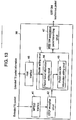
- Fig. 13 shows a configuration of an IEEE1394 interface in the second exemplary embodiment.
- Fig. 14 shows a transition of a packet structure in the content receiver in the second exemplary embodiment.
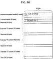
- Figs. 15 and 16 show the structure of a packet transmitted by the IEEE1394 interface.
- Read-out controller 36 reads out the extended TS packet stored in storage device 32 synchronizing with a predetermined frequency clock generated by extended TS packet read-out clock generator 37 according to a command from microcomputer 29.
- a predetermined time interval is inserted between extended TS packets, as shown by S10 in Fig. 14 , before output (S10 in Fig. 14 ).
- This interval is set in response to the clock frequency of clock generator 37 in a way such that a bit rate of extended TS packets after inserting the time interval becomes greater than a bit rate for transmission of extended TS packets by the content transmitter.
- IEEE1394 interface 38 conforms to the IEEE1394 standard, and outputs the extended TS packet input to IEEE1394 interface 38 in an isochronous transfer mode (S11 in Fig. 14 ).
- S11 ISO is an header added in the IEEE1394 interface.
- a transmission signal between read-out controller 36 and IEEE1394 interface 38 is composed in the same way as MPEG2-TS, i.e., data signal, clock signal, packet start signal, and data enable signal.
- the microcomputer sets extended TS packet information to IEEE1394 interface 38. Details are described below.
- Fig. 13 shows a configuration of the IEEE1394 interface.
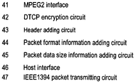
- a stream of the extended TS packets is input to MPEG2 interface 41.
- DTCP encryption circuit 42 encrypts the extended TS packet output from MPEG2 interface 41 in accordance with the DTCP (Digital Transmission Content Protection) standard for protecting the copyright.
- Header adding circuit 43 adds the header to the DTCP-encrypted packet, and outputs this packet. This header is a header required for isochronous transfer.
- Packet format information adding circuit 44 receives information for designating an extended TS packet format from the microcomputer via host interface 46. Packet format information adding circuit 44 then writes the data format of the packet to be ischronously transferred and information for identifying the extended TS packet at a predetermined position in the header.
- the microcomputer inputs information designating the data size of the extended TS packet to packet data size information adding circuit 45 via host interface 46. Packet data size information adding circuit 45 then calculates and determines the data size of the isochronous packet based on this information. Or, the microcomputer inputs information on the size of the isochronous packet for storing the extended TS packet to packet data size information adding circuit 45 via host interface 46. Packet data size information adding circuit 45 then writes information on the data size of the packet to be isochronously transferred at a predetermined position in the header.
- Figs. 15 and 16 show a format different from IEC61883-4 which specifies about the MPEG2 packet.
- Fig. 15 shows an example of adding only the isochronous header to the extended TS packet. In this case, only the packet data size is written in the data length region shown in Fig. 15 . If the data size of the extended TS packet is 192 bytes, data of 588 bytes which is the sum of 576 bytes, three times of 192 bytes; and 12 bytes for the isochronous header and data CRC is written in the data length region in Fig. 15 .
- Fig. 16 shows an example that the extended TS packet has the isochronous header and common header.
- the packet data size is written in the data length region of the isochronous header in Fig. 16
- information for identifying the extended TS packet is written in the format region of the common header.
- the data size of the extended TS packet is 192 bytes, 588 bytes, which is the sum of 4 bytes for reserved region and 192 multiplied by 3;20 bytes for isochronous header, common header, and data CRC; and 4 bytes for the reserved region are added, and data of 612 bytes is written in the region shown in Fig. 16 .
- the reserved region is a region secured for a future extension.
- Information for identifying the extended TS packet is data predetermined with the content transmitting party after excluding any data already in operation.
- Figs. 15 and 16 show an example of the isochronous packet storing three extended TS packets, but the number of packets is not limited to three.
- the number of packets can be 4, 2, or 1.
- the data size of the extended TS packet is 192 bytes in the example, but this is not particularly limited.
- the data size of the extended TS packet can be 196 bytes.
- IEEE1394 isochronous packet transmitting circuit 47 shown in Fig. 13 is configured with a circuit realizing a protocol of a data link layer and physical layer in accordance with the IEEE1394 standard. IEEE1394 isochronous packet transmitting circuit 47 adds the header input to IEEE1394 isochronous packet transmitting circuit 47, and sends the packet to the 1394 bus.
- the second exemplary embodiment can transmit the extended TS packet via the IEEE1394 interface.
- the contents receiver in the second exemplary embodiment can also realize the effect described in the first exemplary embodiment even with the configuration that the TS decoder (not illustrated) and AV decoder (not illustrated) are separately connected to the 1394 bus.
- the content receiver of the present invention prevents decoding errors when a packet loss occurs on a communications network due to difficulty in compensating for the loss at the receiving party. Accordingly, the present invention is applicable to digital television broadcast receivers, personal computers, mobile phones, PDAs, and mobile phone adapters.
- the content transmitter of the present invention allows storage of data efficiently in the storage device by ignoring the data arrival time at the receiving party. During reproduction, data can be reproduced at the level of accuracy required by the decoder using the time stamp indicating the time to output to the decoder. This prevents decoding errors that occur when the jitter compensation accuracy is insufficient to permit decoding. Accordingly, the present invention is effective for digital television broadcast receivers, personal computers, mobile phones, PDAs, and mobile phone adapters.
Landscapes
- Engineering & Computer Science (AREA)
- Signal Processing (AREA)
- Multimedia (AREA)
- Computer Security & Cryptography (AREA)
- Computer Networks & Wireless Communication (AREA)
- Two-Way Televisions, Distribution Of Moving Picture Or The Like (AREA)
- Data Exchanges In Wide-Area Networks (AREA)
- Television Systems (AREA)
- Compression Or Coding Systems Of Tv Signals (AREA)
Claims (16)
- Inhaltsempfänger (21) zum Empfangen von Inhalt, der aus einem Strom von Superkapseln von einem Inhaltssender (11) durch ein Kommunikationsnetzwerk ausgebildet ist, und zum Reproduzieren des Inhalts, wobei jede der Superkapseln aus wenigstens einem erweiterten Transportpaket ausgebildet ist, wobei jedes der wenigstens einen erweiterten Transportpakete aus codierten gesendeten Transportpaketen und Reproduktionszeit-Anweisungsinformationen ausgebildet ist, wobei der Inhaltsempfänger (21) umfasst:eine Speichereinrichtung (32), die angepasst ist, um die in den empfangenen Superkapseln enthaltenen erweiterten Transportpakete zu speichern;eine Systemtaktreproduktionseinrichtung (33), die angepasst ist, um einen Systemtakt zu reproduzieren:einen ersten Zähler, der angepasst ist, um den von der Systemtaktreproduktionseinrichtung ausgegeben Systemtakt zu zählen; undeine Reproduktionseinrichtung (33), die angepasst ist, um den Inhalt zu reproduzieren,wobei,wenn die Diskontinuität der Superkapsel erkannt wird, indem die Kontinuität der Superkapselzählinformationen bestätigt wird, der Inhaltsempfänger (21) eine Neusendeanforderung der im Netzwerk fehlenden Superkapsel an den Inhaltssender (11) sendet,erweiterte Transportpakete, die in der vom Inhaltssender (11) neu gesendeten Superkapsel enthalten sind, in der Speichereinrichtung gespeichert werden,die Reproduktionseinrichtung (33) angepasst ist, um jedes der erweiterten Transportpakete zu reproduzieren, die zu einem Zeitpunkt gespeichert sind, zu dem eine Zählung des ersten Zählers und die Reproduktionszeit-Anweisungsinformationen nach einem vorgegebenen Versatz übereinstimmen,dadurch gekennzeichnet, dass,wenn eine Diskontinuität der Superkapsel im Netzwerk erkannt wird, eine Dummy Superkapsel mit erweiterten Dummy Transportpaketen erzeugt wird und die erweiterten Dummy Transportpakete in der Speichereinrichtung (32) gespeichert werden, wobei dann die in der neu gesendeten Superkapsel enthaltenen erweiterten Dummy Transportpakete so gesteuert werden, dass die erweiterten Dummy Transportpakete in der Speichereinrichtung (32) überschrieben werden;wobei ein und mehrere erweiterte Transportpakete verkapselt sind und der Inhaltsempfänger eine Superkapsel empfängt, in der Superkapselzählinformationen und Superkapselinformationen, die den Inhalt des erweiterten Transportpakets in der Superkapsel anzeigen, zur Superkapsel hinzugefügt werden; unddes Weiteren umfassend eine Speichersteuereinrichtung zum Steuern eines einzelnen Speicherbereiches auf der Basis der Superkapselinformationen und der Superkapselzählinformationen beim Speichern des erweiterten Transportpakets in der empfangenen Superkapsel in die Speichereinrichtung;wobei, wenn eine Diskontinuität der Superkapsel erkannt wird, indem die Kontinuität der Superkapselzählinformationen bestätigt wird, ein Neusendeanforderungsbefehl mit den Superkapselzählinformationen erzeugt und an den Inhaltssender (11) gesendet wird;und Diskontinuität bei der Reproduktion durch Steuern in einer Weise gelöst wird, um das erweiterte Transportpaket in einer anwendbaren Superkapsel, die neu gesendet und von dem Inhaltssender (11) empfangen wird, in einem Bereich zu speichern, der durch die Speichersteuereinrichtung auf der Basis der Superkapselzählinformationen gesteuert wird; undwobei, wenn eine Diskontinuität der Superkapsel erkannt wird, eine Dummy Superkapsel erzeugt und in der Speichereinrichtung (32) anstelle der fehlenden Superkapsel gespeichert wird und eine anwendbare neu gesendete Superkapsel so gesteuert wird, dass die gespeicherte Dummy Superkapsel überschrieben wird.
- Inhaltssender (11), der angepasst ist, um den Inhalt an den Inhaltsempfänger (21) nach Anspruch 1 zu senden, umfassend:eine Sendeeinrichtung (11), die angepasst ist, um den Inhalt zu senden; undeinen zweiten Zähler, der angepasst ist, um einen Systemtakt zu zählen, der angepasst ist, um die Transportpakete zu kodieren;wobei die Sendeeinrichtung (11) jede Superkapsel sendet, die das erweiterte Transportpaket verkapselt, das durch Hinzufügen einer Zahl, die von dem zweiten Zähler als Reproduktionszeit-Anweisungsinformationen zum Anweisen der Reproduktionszeit-Anweisungsinformationen gebildet wurde, um aus der Speichereinrichtung (32) des Inhaltsempfängers (21) für jeden der Transportpakete und der Superkapselzählinformationen zu reproduzieren,wobei die Sendeeinrichtung (11) eine Superkapsel entsprechend der Neusendeanforderung vom Inhaltsempfänger (21) zum Inhaltsempfänger (21) neu sendet.
- Inhaltsempfänger (21) nach Anspruch 1, wobei jede der Superkapseln des Weiteren Superkapselinformationen aufweist, die einen Inhalt von jedem der erweiterten Transportpakete darin anzeigen.
- Inhaltssender (11) nach Anspruch 2, wobei jede der Superkapseln des Weiteren Superkapselinformationen aufweist, die einen Inhalt von jedem der erweiterten Transportpakete darin anzeigen.
- Inhaltsempfänger (21) nach Anspruch 3, der des Weiteren eine Speichersteuereinrichtung (28) umfasst, die angepasst ist, um einen einzelnen Speicherbereich auf der Basis der Superkapselinformationen und der Superkapselzählinformationen zum Speichern der erweiterten Transportpakete in der empfangenen Superkapsel und der erweiterten Dummy Transportpakete in der Dummy Superkapsel in die Speichereinrichtung zu steuern;
wobei das erweiterte Transportpaket in der neu gesendeten Superkapsel in einer Weise gesteuert wird, dass in einem von der Speichersteuereinrichtung (28) gesteuerten Bereich auf der Basis der Superkapselzählinformationen überschrieben wird. - Inhaltsempfänger (21) nach Anspruch 5, wobei, wenn eine Diskontinuität in einer Richtung, die gleich der Zählung ist, beim Bestätigen der Kontinuität der Superkapselzählinformationen erfasst wird, die fehlende Superkapsel erkannt wird.
- Inhaltsempfänger (21) nach einem der Ansprüche 3, 5 und 6, wobei die Anzahl der in jeder der Superkapseln gespeicherten erweiterten Transportpakete in einer derartigen Weise eingestellt ist, dass die Datengröße eines Datenbereiches in den Paketen beim Senden innerhalb der maximalen Sendeeinheit (Maximum Transmission Unit) MTU des Kommunikationsnetzes liegt.
- Inhaltssender (11) nach Anspruch 4, wobei die Anzahl der in jeder der Superkapseln gespeicherten erweiterten Transportpakete in einer derartigen Weise eingestellt ist, dass die Datengröße eines Datenbereiches in den Paketen beim Senden innerhalb der MTU (Maximum Transmission Unit) des Kommunikationsnetzes liegt.
- Inhaltsempfänger (21) nach einem der Ansprüche 1, 3, 5, 6 und 7, der des Weiteren ein Entschlüsselungsgerät umfasst, wobei das Entschlüsselungsgerät (25) angepasst ist, um die Transportpakete nach dem Entfernen der Reproduktionszeit-Anweisungsinformationen zu entschlüsseln, wobei die Reproduktionszeit-Anweisungsinformationen neu hinzugefügt werden, um die erweiterten Transportpakete zu reproduzieren, und die erweiterten Transportpakete in der Speichereinrichtung (32) gespeichert werden.
- Inhaltssender (11) nach einem der Ansprüche 2, 4 und 8, der des Weiteren ein Verschlüsselungsgerät (6) umfasst, wobei die Reproduktionszeit-Anweisungsinformationen zu den Transportpaketen nach dem Verschlüsseln hinzugefügt werden.
- Inhaltsempfänger (21) nach Anspruch 9, wobei der Inhaltsempfänger angepasst ist, um den Strom von dem Inhaltssender (11) nach Anspruch 10 zu empfangen.
- Inhaltsempfänger (21) nach einem der Ansprüche 1, 3, 5, 6, 7 und 9, wobei das in einem Datenbereich des IP Datagramms in einem IP Protokoll gespeicherte erweiterte Transportpaket beim Speichern des Stroms in einem von dem Inhaltssender (11) über ein IP Protokollnetzwerk zur Speichereinrichtung empfangenen IP Paket extrahiert wird.
- Inhaltssender (11) nach einem der Ansprüche 2, 4, 8 und 10, wobei das erweiterte Transportpaket in einem Datenbereich (15) eines IP Datagramms in einem IP Protokoll gespeichert wird und dann ein IP Paket zum Inhaltsempfänger über ein IP Protokollnetzwerk gesendet wird.
- Inhaltsempfänger (21) nach Anspruch 12, wobei der Inhaltsempfänger den Strom von dem Inhaltssender (11) nach Anspruch 13 empfängt.
- Inhaltsempfänger (21) nach Anspruch 1, der des Weiteren eine IEEE1394 Schnittstelle umfasst, wobei die IEEE1394 Schnittstelle das reproduzierte erweiterte Transportpaket empfängt, Informationen zum Identifizieren des erweiterten Transportpakets zu dem Paket hinzufügt und das Paket an einen IEEE 1394 Bus sendet.
- Inhaltsempfänger (21) nach Anspruch 1, wobei die Speichereinrichtung (28) die erweiterten Transportpakete nacheinander in einem Speicherbereich (32) speichert, ohne die Reproduktionszeit-Anweisungsinformationen hinzuzufügen.
Applications Claiming Priority (3)
| Application Number | Priority Date | Filing Date | Title |
|---|---|---|---|
| JP2002206780 | 2002-07-16 | ||
| JP2002206780 | 2002-07-16 | ||
| PCT/JP2003/009043 WO2004008760A1 (ja) | 2002-07-16 | 2003-07-16 | コンテンツ受信器およびコンテンツ送信器 |
Publications (3)
| Publication Number | Publication Date |
|---|---|
| EP1553774A1 EP1553774A1 (de) | 2005-07-13 |
| EP1553774A4 EP1553774A4 (de) | 2011-05-25 |
| EP1553774B1 true EP1553774B1 (de) | 2019-03-13 |
Family
ID=30112803
Family Applications (1)
| Application Number | Title | Priority Date | Filing Date |
|---|---|---|---|
| EP03741425.7A Expired - Lifetime EP1553774B1 (de) | 2002-07-16 | 2003-07-16 | Inhaltsempfangsvorrichtung und inhaltssendevorrichtung |
Country Status (7)
| Country | Link |
|---|---|
| US (2) | US7830881B2 (de) |
| EP (1) | EP1553774B1 (de) |
| JP (3) | JP4042745B2 (de) |
| KR (2) | KR100784874B1 (de) |
| CN (1) | CN1669320B (de) |
| AU (1) | AU2003281136A1 (de) |
| WO (1) | WO2004008760A1 (de) |
Families Citing this family (40)
| Publication number | Priority date | Publication date | Assignee | Title |
|---|---|---|---|---|
| US8270479B2 (en) * | 1999-04-06 | 2012-09-18 | Broadcom Corporation | System and method for video and audio encoding on a single chip |
| CN1669320B (zh) | 2002-07-16 | 2011-03-23 | 松下电器产业株式会社 | 内容接收器 |
| KR100608715B1 (ko) * | 2003-09-27 | 2006-08-04 | 엘지전자 주식회사 | QoS보장형 멀티미디어 스트리밍 서비스 시스템 및 방법 |
| JP2005204001A (ja) * | 2004-01-15 | 2005-07-28 | Hitachi Ltd | データ配信サーバ、ソフトウェア、及びシステム |
| KR100631758B1 (ko) * | 2004-05-04 | 2006-10-09 | 삼성전자주식회사 | 멀티 스트리밍 포맷을 지원하는 네트워크 i/f 카드 및그 방법 |
| JP4491290B2 (ja) * | 2004-06-29 | 2010-06-30 | 日本電気通信システム株式会社 | パケットエラー監視型mpegデコーダ、mpeg映像伝送システム及びmpeg映像伝送方法 |
| US20060007943A1 (en) * | 2004-07-07 | 2006-01-12 | Fellman Ronald D | Method and system for providing site independent real-time multimedia transport over packet-switched networks |
| US7551606B2 (en) * | 2004-08-20 | 2009-06-23 | Sony Corporation | Isochronous transmission for IP-oriented network |
| JP4421537B2 (ja) * | 2005-09-14 | 2010-02-24 | 株式会社東芝 | ストリーム生成装置 |
| KR100739740B1 (ko) * | 2005-10-17 | 2007-07-13 | 삼성전자주식회사 | 방송 녹화 장치 및 방법 |
| KR100800690B1 (ko) * | 2006-02-10 | 2008-02-01 | 삼성전자주식회사 | 디지털 방송 서비스 시스템에서 방송 데이터 전송 장치 및방법 |
| FR2898453A1 (fr) * | 2006-03-13 | 2007-09-14 | Thomson Licensing Sas | Transmission d'un signal genlock sur un reseau ip |
| JP2007266875A (ja) * | 2006-03-28 | 2007-10-11 | Toshiba Corp | 映像データの処理方法及び無線通信装置 |
| JP2007329606A (ja) * | 2006-06-07 | 2007-12-20 | Hitachi Ltd | 中継装置 |
| US7672393B2 (en) * | 2006-08-02 | 2010-03-02 | Richtek Technology Corporation | Single-wire asynchronous serial interface |
| US8363541B2 (en) * | 2006-12-22 | 2013-01-29 | Pratt & Whitney Canada Corp. | Serial digital communication protocol |
| US8145775B2 (en) * | 2007-05-08 | 2012-03-27 | Canon Kabushiki Kaisha | Method to receive UDP response messages across multiple incoming UDP ports |
| EP2028857A1 (de) * | 2007-08-21 | 2009-02-25 | Alcatel Lucent | Verfahren und System zur Unterbrechung und Wiederaufnahme eines Echtzeitdatenstroms |
| JP5101964B2 (ja) * | 2007-09-25 | 2012-12-19 | 京セラ株式会社 | 受信装置 |
| JP5101965B2 (ja) * | 2007-09-25 | 2012-12-19 | 京セラ株式会社 | 受信装置 |
| JP5101967B2 (ja) * | 2007-09-26 | 2012-12-19 | 京セラ株式会社 | 受信装置 |
| US8477793B2 (en) * | 2007-09-26 | 2013-07-02 | Sling Media, Inc. | Media streaming device with gateway functionality |
| US7908404B1 (en) * | 2007-11-09 | 2011-03-15 | Qlogic, Corporation | Method and system for managing network and storage data |
| JP5321923B2 (ja) * | 2008-03-27 | 2013-10-23 | 日本電気株式会社 | クロック同期システム、ノード、クロック同期方法及びプログラム |
| FR2939993B1 (fr) * | 2008-12-12 | 2010-12-17 | Canon Kk | Procede de transmission d'un flux de donnees multi-canal sur un tunnel multi-transport, produit programme d'ordinateur, moyen de stockage et tetes de tunnel correspondantes |
| JP5549221B2 (ja) * | 2009-12-28 | 2014-07-16 | ソニー株式会社 | 再生装置、再生制御方法、およびプログラム |
| US8514329B2 (en) | 2011-05-31 | 2013-08-20 | Motorola Mobility Llc | Jitter estimation for MPEG receivers |
| JP2012257041A (ja) | 2011-06-08 | 2012-12-27 | Sony Corp | 通信装置、通信システム、通信方法及びプログラム |
| US9451313B2 (en) * | 2011-06-29 | 2016-09-20 | Harman International Industries, Incorporated | Network media adapter |
| JP2015507407A (ja) * | 2011-12-28 | 2015-03-05 | インテル コーポレイション | ビデオエンコーディングシステムにおける集積メタデータ挿入システム及び方法 |
| US20140369222A1 (en) * | 2012-01-26 | 2014-12-18 | Electronics And Telecommunications Research Institute | Method for estimating network jitter in apparatus for transmitting coded media data |
| GB2499261B (en) * | 2012-02-10 | 2016-05-04 | British Broadcasting Corp | Method and apparatus for converting audio, video and control signals |
| WO2013173683A1 (en) * | 2012-05-18 | 2013-11-21 | Motorola Mobility Llc | Synchronizing multiple transcoding devices utilizing simultaneity of receipt of multicast packets |
| JP6505413B2 (ja) * | 2013-11-08 | 2019-04-24 | パナソニック インテレクチュアル プロパティ コーポレーション オブ アメリカPanasonic Intellectual Property Corporation of America | 送信方法、受信方法、送信装置、及び受信装置 |
| JP6298305B2 (ja) * | 2014-01-23 | 2018-03-20 | 株式会社メディアリンクス | 放送信号ip伝送システムおよび放送信号ip伝送方法 |
| CN110071785B (zh) * | 2014-06-24 | 2021-10-26 | 株式会社索思未来 | 接口方法 |
| US9723610B2 (en) | 2015-04-07 | 2017-08-01 | Qualcomm Incorporated | Multi-layer timing synchronization framework |
| CN108600861A (zh) * | 2018-03-26 | 2018-09-28 | 南京地铁建设有限责任公司 | 基于城市轨道乘客信息系统的音视频数据包包长调整方法 |
| US10848539B2 (en) | 2018-09-20 | 2020-11-24 | Cisco Technology, Inc. | Genlock mechanism for software pacing of media constant bit rate streams |
| JP7210272B2 (ja) * | 2018-12-28 | 2023-01-23 | 株式会社東芝 | 放送システム、エンコーダ、多重化装置、多重化方法、系統切替装置、および同期制御装置 |
Family Cites Families (44)
| Publication number | Priority date | Publication date | Assignee | Title |
|---|---|---|---|---|
| JPS56160157A (en) * | 1980-04-22 | 1981-12-09 | Sony Corp | Bit clock reproducing circuit |
| US20010013123A1 (en) * | 1991-11-25 | 2001-08-09 | Freeman Michael J. | Customized program creation by splicing server based video, audio, or graphical segments |
| JPH07212245A (ja) | 1994-01-26 | 1995-08-11 | Sony Corp | データ転送回路 |
| JP3371174B2 (ja) * | 1994-09-22 | 2003-01-27 | ソニー株式会社 | パケット受信装置 |
| JP3617655B2 (ja) * | 1994-11-10 | 2005-02-09 | ソニー株式会社 | エンコードシステムおよびエンコード方法、デコードシステムおよびデコード方法、エンコードデータ記録装置およびエンコードデータ記録方法、エンコードデータ伝送装置およびエンコードデータ伝送方法、並びに記録媒体 |
| US5901149A (en) * | 1994-11-09 | 1999-05-04 | Sony Corporation | Decode and encode system |
| JP3440390B2 (ja) * | 1995-03-01 | 2003-08-25 | 日本電信電話株式会社 | 等時性保証型連続メディア伝送装置及び等時性保証型連続メディア伝送方法及び受信装置 |
| US5920572A (en) * | 1995-06-30 | 1999-07-06 | Divicom Inc. | Transport stream decoder/demultiplexer for hierarchically organized audio-video streams |
| US5822317A (en) * | 1995-09-04 | 1998-10-13 | Hitachi, Ltd. | Packet multiplexing transmission apparatus |
| WO1997037239A1 (en) * | 1996-03-29 | 1997-10-09 | Lawrence Berkeley National Laboratory | Enhancement of nmr and mri in the presence of hyperpolarized noble gases |
| JPH10313350A (ja) * | 1997-05-13 | 1998-11-24 | Matsushita Electric Ind Co Ltd | 通信システム |
| JP3400681B2 (ja) * | 1997-07-16 | 2003-04-28 | 株式会社日立製作所 | データパケット再多重方法及び再多重装置 |
| AR016812A1 (es) * | 1997-08-14 | 2001-08-01 | Samsung Electronics Co Ltd | Metodo para transmitir informacion de video comprimida, disposiciones de compresion y de grabacion de video y aparato de reproduccion de video |
| JP4109735B2 (ja) * | 1997-09-05 | 2008-07-02 | 株式会社日立製作所 | パケット変換方法、伝送方法、mpegプロトコルとipの変換方法、catvシステム、プロトコル変換方法およびパケット送信方法 |
| EP0901261B1 (de) * | 1997-09-05 | 2013-01-09 | Hitachi, Ltd. | Verfahren und Anordnung zur Umsetzung von Übertragungsprotokollen |
| JP3017983B2 (ja) * | 1997-11-19 | 2000-03-13 | 株式会社ケンウッド | 同期捕捉回路 |
| JP3642180B2 (ja) * | 1998-04-24 | 2005-04-27 | 三菱電機株式会社 | クロック再生装置 |
| SG71835A1 (en) * | 1998-09-07 | 2000-04-18 | Victor Company Of Japan | A dejittering and clock recovery technique for real-time audio/visual network applications |
| US6587985B1 (en) * | 1998-11-30 | 2003-07-01 | Matsushita Electric Industrial Co., Ltd. | Data transmission method, data transmission apparatus, data receiving apparatus, and packet data structure |
| JP2000173181A (ja) * | 1998-12-04 | 2000-06-23 | Sony Corp | データ記録装置及び出力装置、データ出力システム、データ記録方法及び出力方法、並びにデータ記録及び出力方法 |
| US20060262813A1 (en) * | 1998-12-18 | 2006-11-23 | Digital Networks North America, Inc. | Multi-channel video pump |
| US6493832B1 (en) * | 1999-03-17 | 2002-12-10 | Sony Corporation | Communication apparatus which handles a time stamp |
| JP4081936B2 (ja) * | 1999-03-17 | 2008-04-30 | ソニー株式会社 | 通信装置、通信方法、および記録媒体 |
| JP2000307637A (ja) * | 1999-04-16 | 2000-11-02 | Nec Corp | マルチメディア端末装置及び網間接続装置 |
| US6792615B1 (en) * | 1999-05-19 | 2004-09-14 | New Horizons Telecasting, Inc. | Encapsulated, streaming media automation and distribution system |
| JP2001016267A (ja) | 1999-07-01 | 2001-01-19 | Sony Corp | 通信装置および方法、並びに媒体 |
| JP4271787B2 (ja) * | 1999-07-29 | 2009-06-03 | 日本電信電話株式会社 | 通信システム |
| JP4193297B2 (ja) * | 1999-08-04 | 2008-12-10 | ソニー株式会社 | 通信装置および方法、通信システム、並びに記録媒体 |
| JP4129664B2 (ja) * | 1999-10-05 | 2008-08-06 | ソニー株式会社 | データ処理装置およびデータ処理方法 |
| JP4407007B2 (ja) * | 2000-05-02 | 2010-02-03 | ソニー株式会社 | データ送信装置及び方法 |
| JP3630406B2 (ja) * | 2000-07-17 | 2005-03-16 | 松下電器産業株式会社 | パケット処理装置、パケット処理方法及びその記憶媒体 |
| JP2002051321A (ja) | 2000-08-04 | 2002-02-15 | Sony Corp | デジタルビデオ送信機、デジタルビデオ受信機及びデジタルビデオ送受信機 |
| JP3748376B2 (ja) * | 2000-08-22 | 2006-02-22 | 松下電器産業株式会社 | 送信装置、ソースパケット生成装置、パケット形態決定方法、及び記録媒体 |
| WO2002029991A1 (en) * | 2000-10-05 | 2002-04-11 | Provisionpoint Communications, Llc | Group packet encapsulation and compression system and method |
| KR20020032730A (ko) * | 2000-10-27 | 2002-05-04 | 구자홍 | 데이터 재전송 장치 및 그 방법 |
| US7023924B1 (en) * | 2000-12-28 | 2006-04-04 | Emc Corporation | Method of pausing an MPEG coded video stream |
| US20040114908A1 (en) * | 2001-03-29 | 2004-06-17 | Masanori Ito | Av data recording/reproducing apparatus and method for the same, and disc on which data is recorded by the av data recording/reproducing apparatus or method |
| US6907081B2 (en) * | 2001-03-30 | 2005-06-14 | Emc Corporation | MPEG encoder control protocol for on-line encoding and MPEG data storage |
| US20030198223A1 (en) * | 2002-04-23 | 2003-10-23 | General Instrument Corporation | Method and apparatus for identifying data streams as networks |
| US7061942B2 (en) * | 2002-05-31 | 2006-06-13 | Skystream Networks Inc. | Apparatus for redundant multiplexing and remultiplexing of program streams and best effort data |
| CN1669320B (zh) | 2002-07-16 | 2011-03-23 | 松下电器产业株式会社 | 内容接收器 |
| US7349386B1 (en) * | 2003-02-18 | 2008-03-25 | Cisco Technology, Inc. | Method and apparatus for transporting MPEG streams on IP networks including removing null packets |
| KR101135224B1 (ko) * | 2004-02-17 | 2012-04-23 | 파나소닉 주식회사 | 기록매체, 재생장치, 프로그램 및 재생방법 |
| JP5994653B2 (ja) * | 2013-01-23 | 2016-09-21 | マツダ株式会社 | 火花点火式多気筒エンジンの始動装置 |
-
2003
- 2003-07-16 CN CN038164469A patent/CN1669320B/zh not_active Expired - Fee Related
- 2003-07-16 WO PCT/JP2003/009043 patent/WO2004008760A1/ja active Application Filing
- 2003-07-16 AU AU2003281136A patent/AU2003281136A1/en not_active Abandoned
- 2003-07-16 KR KR1020067022351A patent/KR100784874B1/ko active IP Right Grant
- 2003-07-16 US US10/515,528 patent/US7830881B2/en not_active Expired - Fee Related
- 2003-07-16 KR KR20057000783A patent/KR100709484B1/ko active IP Right Grant
- 2003-07-16 JP JP2004521223A patent/JP4042745B2/ja not_active Expired - Lifetime
- 2003-07-16 EP EP03741425.7A patent/EP1553774B1/de not_active Expired - Lifetime
-
2010
- 2010-06-14 JP JP2010134745A patent/JP5170166B2/ja not_active Expired - Fee Related
- 2010-06-14 JP JP2010134744A patent/JP4666110B2/ja not_active Expired - Lifetime
- 2010-10-06 US US12/899,074 patent/US8503471B2/en not_active Expired - Fee Related
Non-Patent Citations (1)
| Title |
|---|
| None * |
Also Published As
| Publication number | Publication date |
|---|---|
| AU2003281136A1 (en) | 2004-02-02 |
| JPWO2004008760A1 (ja) | 2005-11-17 |
| KR100709484B1 (ko) | 2007-04-20 |
| CN1669320A (zh) | 2005-09-14 |
| JP5170166B2 (ja) | 2013-03-27 |
| CN1669320B (zh) | 2011-03-23 |
| US20050237434A1 (en) | 2005-10-27 |
| US7830881B2 (en) | 2010-11-09 |
| WO2004008760A1 (ja) | 2004-01-22 |
| KR20060132017A (ko) | 2006-12-20 |
| KR20050025607A (ko) | 2005-03-14 |
| KR100784874B1 (ko) | 2007-12-14 |
| JP2010226766A (ja) | 2010-10-07 |
| US20110023078A1 (en) | 2011-01-27 |
| JP4042745B2 (ja) | 2008-02-06 |
| EP1553774A1 (de) | 2005-07-13 |
| US8503471B2 (en) | 2013-08-06 |
| EP1553774A4 (de) | 2011-05-25 |
| JP2010246146A (ja) | 2010-10-28 |
| JP4666110B2 (ja) | 2011-04-06 |
Similar Documents
| Publication | Publication Date | Title |
|---|---|---|
| EP1553774B1 (de) | Inhaltsempfangsvorrichtung und inhaltssendevorrichtung | |
| US7372858B2 (en) | Data transmission device and data transmission method | |
| RU2273111C2 (ru) | Способ преобразования пакетизированного потока информационных сигналов в поток информационных сигналов с временными отметками и наоборот | |
| US6744782B1 (en) | Communications device, method thereof, communications system and recording medium | |
| JP4216195B2 (ja) | 非同期ネットワークを介するストリームの送信 | |
| US20040260823A1 (en) | Simultaneously transporting multiple MPEG-2 transport streams | |
| CN100401784C (zh) | 数字多媒体数据接收机的数据同步方法和设备 | |
| US7706379B2 (en) | TS transmission system, transmitting apparatus, receiving apparatus, and TS transmission method | |
| KR20100050516A (ko) | 네트워크에서의 데이터 콘텐츠 스트리밍 | |
| JP2009010966A (ja) | 非同期ネットワークを介するストリームの受信 | |
| WO2007022038A2 (en) | Protecting elementary stream content | |
| KR20150083428A (ko) | Mmt 서비스의 패킷 재전송 방법 및 장치, 재전송 요청 방법 및 장치 | |
| JP3045715B2 (ja) | 伝送システム、送信装置、記録再生装置、および記録装置 | |
| JP4192766B2 (ja) | 受信装置および方法、記録媒体、並びにプログラム | |
| JP4135763B2 (ja) | コンテンツ受信器 | |
| JP4561822B2 (ja) | コンテンツ受信機 | |
| WO2008022500A1 (fr) | Procédé de transmission différenciée de l'information de commande et de l'information média d'une diffusion multimédia mobile | |
| JP2006211227A (ja) | データ送信装置およびデータ送信方法 | |
| JPH08307453A (ja) | データ受信装置 |
Legal Events
| Date | Code | Title | Description |
|---|---|---|---|
| PUAI | Public reference made under article 153(3) epc to a published international application that has entered the european phase |
Free format text: ORIGINAL CODE: 0009012 |
|
| 17P | Request for examination filed |
Effective date: 20050112 |
|
| AK | Designated contracting states |
Kind code of ref document: A1 Designated state(s): AT BE BG CH CY CZ DE DK EE ES FI FR GB GR HU IE IT LI LU MC NL PT RO SE SI SK TR |
|
| AX | Request for extension of the european patent |
Extension state: AL LT LV MK |
|
| DAX | Request for extension of the european patent (deleted) | ||
| RBV | Designated contracting states (corrected) |
Designated state(s): DE FR GB |
|
| RAP1 | Party data changed (applicant data changed or rights of an application transferred) |
Owner name: PANASONIC CORPORATION |
|
| A4 | Supplementary search report drawn up and despatched |
Effective date: 20110421 |
|
| 17Q | First examination report despatched |
Effective date: 20121024 |
|
| STAA | Information on the status of an ep patent application or granted ep patent |
Free format text: STATUS: EXAMINATION IS IN PROGRESS |
|
| REG | Reference to a national code |
Ref country code: DE Ref legal event code: R079 Ref document number: 60351869 Country of ref document: DE Free format text: PREVIOUS MAIN CLASS: H04N0007080000 Ipc: H04L0001160000 |
|
| GRAP | Despatch of communication of intention to grant a patent |
Free format text: ORIGINAL CODE: EPIDOSNIGR1 |
|
| STAA | Information on the status of an ep patent application or granted ep patent |
Free format text: STATUS: GRANT OF PATENT IS INTENDED |
|
| INTG | Intention to grant announced |
Effective date: 20181031 |
|
| RIC1 | Information provided on ipc code assigned before grant |
Ipc: H04N 21/6437 20050713ALI20181019BHEP Ipc: H04N 21/235 20050713ALI20181019BHEP Ipc: H04L 1/16 19680901AFI20181019BHEP Ipc: H04N 7/173 19850101ALI20181019BHEP Ipc: H04N 21/643 20050713ALI20181019BHEP Ipc: H04N 21/2381 20050713ALI20181019BHEP Ipc: H04N 21/8547 20050713ALI20181019BHEP Ipc: H04N 21/236 20050713ALI20181019BHEP Ipc: H04N 21/435 20050713ALI20181019BHEP Ipc: H04N 21/2389 20050713ALI20181019BHEP Ipc: H04N 21/6375 20050713ALI20181019BHEP Ipc: H04N 21/61 20050713ALI20181019BHEP |
|
| RIC1 | Information provided on ipc code assigned before grant |
Ipc: H04N 21/2381 20110101ALI20181019BHEP Ipc: H04N 7/173 20110101ALI20181019BHEP Ipc: H04N 21/6375 20110101ALI20181019BHEP Ipc: H04N 21/236 20110101ALI20181019BHEP Ipc: H04N 21/643 20110101ALI20181019BHEP Ipc: H04N 21/235 20110101ALI20181019BHEP Ipc: H04N 21/6437 20110101ALI20181019BHEP Ipc: H04N 21/61 20110101ALI20181019BHEP Ipc: H04N 21/8547 20110101ALI20181019BHEP Ipc: H04N 21/435 20110101ALI20181019BHEP Ipc: H04L 1/16 20060101AFI20181019BHEP Ipc: H04N 21/2389 20110101ALI20181019BHEP |
|
| GRAS | Grant fee paid |
Free format text: ORIGINAL CODE: EPIDOSNIGR3 |
|
| GRAA | (expected) grant |
Free format text: ORIGINAL CODE: 0009210 |
|
| STAA | Information on the status of an ep patent application or granted ep patent |
Free format text: STATUS: THE PATENT HAS BEEN GRANTED |
|
| RIC1 | Information provided on ipc code assigned before grant |
Ipc: H04L 1/16 20060101AFI20181019BHEP Ipc: H04N 21/6437 20110101ALI20181019BHEP Ipc: H04N 21/2389 20110101ALI20181019BHEP Ipc: H04N 21/235 20110101ALI20181019BHEP Ipc: H04N 21/643 20110101ALI20181019BHEP Ipc: H04N 7/173 20110101ALI20181019BHEP Ipc: H04N 21/8547 20110101ALI20181019BHEP Ipc: H04N 21/2381 20110101ALI20181019BHEP Ipc: H04N 21/236 20110101ALI20181019BHEP Ipc: H04N 21/435 20110101ALI20181019BHEP Ipc: H04N 21/61 20110101ALI20181019BHEP Ipc: H04N 21/6375 20110101ALI20181019BHEP |
|
| AK | Designated contracting states |
Kind code of ref document: B1 Designated state(s): DE FR GB |
|
| REG | Reference to a national code |
Ref country code: GB Ref legal event code: FG4D |
|
| REG | Reference to a national code |
Ref country code: DE Ref legal event code: R096 Ref document number: 60351869 Country of ref document: DE |
|
| PGFP | Annual fee paid to national office [announced via postgrant information from national office to epo] |
Ref country code: FR Payment date: 20190719 Year of fee payment: 17 Ref country code: DE Payment date: 20190719 Year of fee payment: 17 |
|
| REG | Reference to a national code |
Ref country code: DE Ref legal event code: R097 Ref document number: 60351869 Country of ref document: DE |
|
| PGFP | Annual fee paid to national office [announced via postgrant information from national office to epo] |
Ref country code: GB Payment date: 20190719 Year of fee payment: 17 |
|
| PLBE | No opposition filed within time limit |
Free format text: ORIGINAL CODE: 0009261 |
|
| STAA | Information on the status of an ep patent application or granted ep patent |
Free format text: STATUS: NO OPPOSITION FILED WITHIN TIME LIMIT |
|
| 26N | No opposition filed |
Effective date: 20191216 |
|
| REG | Reference to a national code |
Ref country code: DE Ref legal event code: R119 Ref document number: 60351869 Country of ref document: DE |
|
| GBPC | Gb: european patent ceased through non-payment of renewal fee |
Effective date: 20200716 |
|
| PG25 | Lapsed in a contracting state [announced via postgrant information from national office to epo] |
Ref country code: FR Free format text: LAPSE BECAUSE OF NON-PAYMENT OF DUE FEES Effective date: 20200731 Ref country code: GB Free format text: LAPSE BECAUSE OF NON-PAYMENT OF DUE FEES Effective date: 20200716 |
|
| PG25 | Lapsed in a contracting state [announced via postgrant information from national office to epo] |
Ref country code: DE Free format text: LAPSE BECAUSE OF NON-PAYMENT OF DUE FEES Effective date: 20210202 |