EP1548368B1 - Satz von Schubladen-Dunstabzugshauben - Google Patents
Satz von Schubladen-Dunstabzugshauben Download PDFInfo
- Publication number
- EP1548368B1 EP1548368B1 EP04025061.5A EP04025061A EP1548368B1 EP 1548368 B1 EP1548368 B1 EP 1548368B1 EP 04025061 A EP04025061 A EP 04025061A EP 1548368 B1 EP1548368 B1 EP 1548368B1
- Authority
- EP
- European Patent Office
- Prior art keywords
- parts
- drawer
- set according
- extractor
- packing
- Prior art date
- Legal status (The legal status is an assumption and is not a legal conclusion. Google has not performed a legal analysis and makes no representation as to the accuracy of the status listed.)
- Expired - Lifetime
Links
- 238000012856 packing Methods 0.000 claims description 31
- 229910052782 aluminium Inorganic materials 0.000 claims description 3
- XAGFODPZIPBFFR-UHFFFAOYSA-N aluminium Chemical compound [Al] XAGFODPZIPBFFR-UHFFFAOYSA-N 0.000 claims description 3
- 229910052751 metal Inorganic materials 0.000 claims description 3
- 239000002184 metal Substances 0.000 claims description 3
- 239000004411 aluminium Substances 0.000 claims 1
- 238000004806 packaging method and process Methods 0.000 description 97
- 125000006850 spacer group Chemical group 0.000 description 34
- 239000004519 grease Substances 0.000 description 12
- 230000008901 benefit Effects 0.000 description 7
- 238000010276 construction Methods 0.000 description 7
- 239000004033 plastic Substances 0.000 description 6
- 229920006328 Styrofoam Polymers 0.000 description 5
- 238000009434 installation Methods 0.000 description 5
- 238000004519 manufacturing process Methods 0.000 description 5
- 239000008261 styrofoam Substances 0.000 description 5
- 239000003517 fume Substances 0.000 description 3
- 238000000034 method Methods 0.000 description 3
- 230000006641 stabilisation Effects 0.000 description 3
- 238000011105 stabilization Methods 0.000 description 3
- 238000000465 moulding Methods 0.000 description 2
- 230000003287 optical effect Effects 0.000 description 2
- 239000004793 Polystyrene Substances 0.000 description 1
- 229910000831 Steel Inorganic materials 0.000 description 1
- 238000010521 absorption reaction Methods 0.000 description 1
- 230000000712 assembly Effects 0.000 description 1
- 238000000429 assembly Methods 0.000 description 1
- 230000005540 biological transmission Effects 0.000 description 1
- 239000011888 foil Substances 0.000 description 1
- 230000004313 glare Effects 0.000 description 1
- 239000000463 material Substances 0.000 description 1
- 230000008520 organization Effects 0.000 description 1
- 239000002985 plastic film Substances 0.000 description 1
- 229920006255 plastic film Polymers 0.000 description 1
- 229920002223 polystyrene Polymers 0.000 description 1
- 239000000047 product Substances 0.000 description 1
- 230000002787 reinforcement Effects 0.000 description 1
- 238000007790 scraping Methods 0.000 description 1
- 230000035939 shock Effects 0.000 description 1
- 239000010959 steel Substances 0.000 description 1
- 239000006228 supernatant Substances 0.000 description 1
- 230000001502 supplementing effect Effects 0.000 description 1
Images


Classifications
-
- F—MECHANICAL ENGINEERING; LIGHTING; HEATING; WEAPONS; BLASTING
- F24—HEATING; RANGES; VENTILATING
- F24C—DOMESTIC STOVES OR RANGES ; DETAILS OF DOMESTIC STOVES OR RANGES, OF GENERAL APPLICATION
- F24C15/00—Details
- F24C15/20—Removing cooking fumes
- F24C15/2078—Removing cooking fumes movable
- F24C15/2092—Removing cooking fumes movable extendable or pivotable
Definitions
- the invention relates to the production of cooker hoods including their packaging and assembly.
- Extractor hoods for vacuuming moist or fatty kitchen fumes over hobs and cookers are known per se in many different designs.
- a design that can be referred to as a drawer cooker hood (often referred to as "flat screen hood"), in principle, a body with a suction system and u. U. other louvers and u. U. a connection for an exhaust duct, which body is referred to below as a fan box. Below this fan box, a unit is mounted, which contains a grease filter, wherein a part of this unit can be pulled out in a drawer-like shape to the front, so that increases the total depth of this drawer unit. The removal of this part of the drawer assembly can be done by hand or by motor and coupled with other movements.
- An exemplary drawer cooker hood shows about the DE 42 43 944 A1 ,
- Extractor hoods with other Wrasentuben which can be provided on a base unit, are for example in the EP 0 974 790 A2 and the EP 12 51 318 A2 described.
- cooker hoods are installed in kitchen cabinets or other angleskorpusse, with u. U. only the drawer unit or only part of the same can be seen.
- the following invention is based on the technical problem of providing improved production possibilities for such extractor hoods.
- the invention is directed to a set of a plurality of extractor hoods, each with a fan box, wherein the hoods (1, 4, 6) of the set same fan boxes (2), characterized in that each at the bottom of the fan box a drawer unit mounted is that, and that the hoods of the set in width have different drawer units and that the drawer units have mutually identical frame parts, each serving for attachment to the respective fan box and are adapted in width to the fan box.
- the invention is based on the fact that vapor extractor hoods of the described design already exist in the market of different widths. These designs are built into kitchen cabinets sized for size and are often matched in width to the width of the oven or hob below.
- the width hereby means the horizontal width extension from the perspective of the user standing in front of the stove or hob and operating and using the extractor hood. For example, widths of 60 cm, 70 cm or 90 cm are common.
- the basic idea now is to use a system of cooker hoods, in which only the drawer unit is adapted to the particular desired width or is selected to match this width and the fan box to be used remains the same. So a fan box is used, which can be used with different widths of drawer units. Preferably, the fan box is adapted to the smallest occurring drawer unit width in the system, for example 60 cm, and substantially as wide as this.
- the same fan box can be used with respect to actually overly wide drawer units and thus sucks from laterally projecting areas of the drawer units also from.
- This does not lead to significant technical problems, which is also apparent from the fact that, for example, by extending the movable part of the drawer unit also one, but in depth, on the fan box protruding part is generated, the i. d. R. is also provided with filter surface.
- the inventor has recognized that, for example, with a 90 cm width of the drawer assembly compared to a conventionally used here about 90 cm wide fan box without doubt existing limitations in relation to the advantages of the invention can be accepted.
- the frame part of the drawer assembly which serves for mounting the same on the fan box and usually has substantially the same width as the fan box, identical in all series in the series hoods.
- the same can, for example, for covers of the moving part of the drawer unit including controls u. ⁇ . be valid.
- the grease filter modules may be equipped with expanded metal grease filters or other reusable grease filters or the corresponding retainers be adapted for disposable fat filter, the light strips used and other components that are widened meaningful manner with wider drawer unit.
- the drawer unit is thus constructed from a parts kit, which can also be standardized to a certain extent.
- additional reinforcements can be attached to at least part of the drawer extractor hoods, which connect the aforementioned laterally projecting portions of the drawer units with each other.
- cross members are provided, which thus extend in the width direction and are connected to outside of the mentioned standardized frame parts lying components, such as the guide profiles for the moving parts.
- These crossbeams are of particular interest in the wider drawer units, so they can be omitted at the narrowest width (s), such as the 60 cm wide drawer units.
- the transverse members are aluminum profile rods, in particular L-profiles.
- the crossbeams are preferably screwed to the respective lateral components. They are also preferably arranged so that they are not visible to the user, in particular, a mounting above the grease filter of the finished extractor hood comes into consideration.
- a modular principle can also be used in the packaging of the extractor hoods from this series.
- the invention has a further preferred aspect of a packaging method for the extractor hood, in which a modular set of packaging parts is used which, in addition to the outer, has at least one further inner packaging part.
- This inner packaging part should be arranged between the extractor hood and one of the outer packaging parts and to a certain extent act as a spacer.
- the inner packaging parts can also be used in two or more consecutively, in a sense to build from two or more short a total of long spacer.
- connections between the outer and inner packaging parts are preferably connectors. In principle, no connections must be provided and the outer and inner packaging parts can be simply against each other. However, it is practical if the parts associated with a respective side can be put together even before packaging, so that then only one part per side has to be moved during packaging itself.
- the inner packaging parts are preferably equal to one another, but this is not absolutely necessary. It is also possible to use different, for their function as spacers different "long", inner packaging parts.
- extractor hood that is, according to the nomenclature of claims 4 ff the various parts, do not necessarily have to be packaged with packaging sets which differ from each other only by an inner packaging part.
- an inner packaging part For example, even with a first part of the extractor hoods only the outer packaging parts, in a second part the same and further two inner packaging parts and in a third part correspondingly more inner packaging parts can be used.
- the packaging parts are flat on two opposite sides, one side for each packing part, the fan box abut. This is used for power transmission, because the drawer is often the more mechanically sensitive part of the hood and therefore clamping forces of the package or forces due to external influence when stacking or shock during transport can be better transferred to the more stable fan box. This is one of the advantages of partially conforming the interior shape of the package.
- the packaging parts are also designed so that they not only rest on two opposite sides of the fan box, which are each associated with the packaging parts, but also bear against two other mutually opposite sides of the fan box with other parts of its inner shape. Since the fan box usually has a rectangular cross-section, these two other pages are no longer each assigned to the packaging parts pages but sides where part of the inner shape of both packaging parts can rest. Overall, this can be done in four directions support.
- sides of the extractor hood which are not covered by the packaging parts can be packed without molded parts, for example only by stretched plastic films or the like, or otherwise only packed in a box-shaped packaging, for example an outer carton, as a result of the support by the previously considered molded parts be or be provided with other moldings.
- packaging parts that comply with the principle of this invention and are adapted to more than one side of the hood.
- the packaging parts considered here are foamed plastic molded parts, in particular styrofoam molded parts.
- foamed plastic molded parts in particular styrofoam molded parts.
- the invention also preferably relates to packaging whose outer shape is substantially parallelepiped in finished packaging.
- packaging whose outer shape is substantially parallelepiped in finished packaging.
- parts of the package may exist in which only foils o. ⁇ . have been used.
- the cuboid shape does not refer to slight deviations but to a certain extent means the caving-in three-dimensional shape. Rectangular packagings have the advantage of being able to put together particularly well to save more space during transport and storage and, moreover, are best adapted to various means of transport.
- kitchen cabinet formats can be used, which correspond substantially to the width of the drawer unit.
- the invention i. d. R. already optical reasons, although the invention of course also refers to cases in which the drawer unit protrudes laterally over the kitchen cabinet.
- the invention provides as a further preferred feature, the remaining space in the kitchen carcass usable as storage space and the kitchen user accessible.
- spacer components with which, if desired, a lateral mounting of the fan boxes narrower in relation to the kitchen body can take place on the walls of the kitchen cabinet.
- the basic idea of the invention is to create a free space, an extractor hood with too small a width still on the side
- assemblies on laterally adjacent kitchen corpus walls are common on the one hand, so that the assembly personnel is used to it and for fume hood manufacturers typical fastening systems exist and are controlled. On the other hand, the results are usually more stable.
- a spacer component is proposed which is dimensioned in width such that it fills the remaining space between the extractor hood or its component intended for installation and the kitchen body wall in question.
- Such spacer components are not yet known and also form a certain additional expense because they have to be specially manufactured, supplied and assembled. However, they increase the flexibility in the assembly of cooker hoods so clearly that these disadvantages can be accepted.
- two identical spacer components are used per extractor hood, one on each side, as the embodiment shows.
- spacers may be in a particular embodiment, U-profile sheets, which preferably have Anschraublaschen for the kitchen cabinet wall. They may also preferably have a fastening device for a protruding in width drawer assembly, which is thus arranged during assembly under the spacer member. This creates additional stabilization. In question come in particular screw. It is further preferred that a part of the U-profile sheet, for example one of the two legs, substantially flush with a front of the cooker hood, in particular the fan box concludes. This can have optical reasons if glare is omitted. On the other hand, the spacer member should not be introduced close to the wall for reasons of stability, so that because of the relative to the drawer unit usually recessed construction depth of the fan box such flush termination provides a stable installation. At the same time, the volume remaining in front of the fan box and coming into consideration for storage space is not restricted.
- connection between the fan box and the spacer component according to the invention can likewise be a screw connection.
- a latching connection is provided here with an undercut edge and a spring latching device.
- the undercut edge on an element of the spacer member, such as a bolted plastic block, and the spring latching device is provided in the corresponding wall of the hood or the fan box.
- the hood can be fixed in a particularly simple and fast manner latching between the kitchen carcass walls and optionally additionally braced with screws.
- the bridged by the spacer member width according to the invention should have a significant size, so that the benefits of the invention are relevant at all.
- widths of at least 10% of the corresponding extractor hood width are preferred.
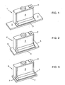
- Fig. 1 shows a hood 1 of the building type with an upper fan box 2 and a drawer assembly mounted thereunder 3.
- the technical details of the fan box 2 are conventional in nature or not relevant to the present invention. It contains blower fans for drawing in kitchen fumes through the drawer unit 3 and in the upper area of the fan box 2 in FIG Fig. 1 identifiable but not numbered connections for an exhaust duct and an electrical power supply.
- the drawer unit 3 which is essentially a flat plate-like unit with over the fan box 2 clearly outgoing width.
- the fan box 2 is about 54 cm wide, the drawer unit 3, however, 90 cm wide. So it stands on the right and the left side about 18 cm above.
- the fan box 2 has in the lower part in consequence of in Fig. 1 recognizable level a slightly greater depth than in the upper area.
- the drawer unit 3 corresponds to this greater depth, thus closing in the depth dimension substantially flush with the fan box 2 from.
- a part of the drawer unit 3 can be drawer style pull forward, the perspective of the Fig. 1 corresponds to the perspective of the user.
- FIGS. 2 and 3 show an extractor hood 4 with drawer unit 5 and an extractor hood 6 with drawer unit 7.
- the differences of the hoods 1, 4 and 6 are limited to the drawer units 3, 5 and 7. These are different widths, namely 70 cm wide in the case of the drawer unit 5 and 60 cm wide in the case of the drawer unit 7.
- the lateral projections are thus 8 cm and 3 cm.
- the extractor hood 6 with the drawer unit 7, the side hardly protrudes beyond the fan box 2, can be considered as far as conventional - apart from structural details - as conventional. It is common in drawers-hoods to align the fan box and the drawer unit in about the same width and also install in a suitably sized kitchen carcass.
- a same fan box 2 is now also used for wider drawer units 5 and 3, which consequently survive laterally, which conventionally not provided for larger losses in the wide drawer units due to certain losses in the flow cross-section and larger building restrictions in the fan unit has been.
- the invention assumes that the technical performance of the fan box 2 is sufficient and the disadvantages can be made up for by a "modular" construction of an extractor hood series with the same fan box 2 by far in comparison to the considerable cost advantages.
- it is possible to design and produce at a more costly location elsewhere or to offer a particularly competitively priced product.
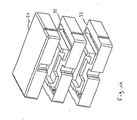
- Fig. 4 shows representative of the drawer units 5 and 7, the drawer unit 3 from Fig. 1 , where in Fig. 4 the movable drawer part is pulled forward. It has a left and right profile slide 8 and 9, between which a standardized for all cooker hoods 1, 4, 6 of this series cover 10 is arranged with controls. In the movable part of the drawer units, the deviations are therefore limited to the respective widths of the lateral profile slide rails 8 and 9.
- the profile slide rails 8 and 9 are displaceably guided in receiving profiles 11 and 12, between which a frame part 13 is mounted.
- the frame part 13 serves with the in Fig. 4 recognizable upward parts for mounting on the fan box 2 and is adapted in width to this.
- the lateral receiving profiles 11 and 12 are in contrast to the standardized frame part 13 in turn adapted for each drawer unit with different width in width, and indeed according to the profile slide rails 8 and 9.
- Fig. 5 shows the drawer unit 3 from Fig. 4 from below, with the grease filters 14 omitted.
- a light strip 15 can be seen, which closes the drawer unit 3 at the user remote end down and can illuminate the hob. Also, this light bar 15 is a wide-matched component, such as Fig. 5 clearly shows.
- Fig. 6 shows the same view as Fig. 5 , but with mounted grease filters 14.
- Fig. 7 shows one in the perspective view Fig. 4 corresponding view.
- the frame part 13 is omitted, however, an integer number of items not numbered throughout are shown to show the structure on this occasion substantially complete.
- the left and right profile slide rails 8, 9 are not only for the 90 cm version included in the Fig. 4-6 is shown, but with the reference numerals 8 ', 9' and 8 ", 9” also drawn for the 70 cm and 60 cm version.
- the profile slide 8 ", 9" in several parts. Incidentally, however, it can be seen that the parts 8, 9 and 8 ', 9' as well as the parts 11, 12, 11 ', 12' and 11 “, 12" are not substantially different from each other except for the widthwise extensions.
- the grease filters 14 are also adapted to the entire width, but here are only drawn simply. All other components in Fig.
- cover 7 can be universally used for 60 cm, 70 cm and 90 cm versions of the cooker hood. This applies in particular next to the already mentioned cover 10 also for a rear cover 53, which in Fig. 4 can be seen in its lower part as the rear end of the frame part 13, and for a larger component 52, the under the cover 10 comes to rest and belongs to the middle construction area of the movable drawer part.
- Fig. 7 indicates with the cable sets that also the cable guides of the basic design can be used for all widened designs. Furthermore, in particular the components 10, 13, 52, 53 are cost-intensive, so that the large numbers result here in consequence of the modular use for different types of construction to significant savings.
- Fig. 7 further shows an elongated aluminum L-profile 51, which can be screwed as a cross-beam with the profile slide rails 8, 9 and 8 ', 9'.
- This cross-beam 51 is mounted about 200 mm from the front edge of the cover 10 above the grease filters 14. It brings a significant increase in the stability of the assembled system of the cover 10, the component 52 (the so-called. Frame drawer) and the side members 8, 9, 11, 12 and 8 ', 9', 11 ', 12'. In particular, the risk of tilting and scraping of the movable drawer part on the receiving profiles 11, 12 and 11 ', 12' is reduced.
- the modular design also has the advantage that the relatively large tolerance variations in larger plastic parts, such as the frame drawer 52, are kept low by the limitation to the 60 cm width and overall so that the ease of installation is maintained even with large drawer units.
- a packaging part 21 is shown in perspective, with an inside with the hitherto so-called inner shape can be seen.
- the outer packaging member 21 has substantially a rectangular outer edge surface 22 and a substantially flat rear side, which is hidden here, but in the later described Fig. 11 you can see.
- the outer edge surface 22 and the back are adapted to a total cuboid shape of the finished package.
- the inner shape of the outer packaging part 21 may be in an in Fig. 8 divided left and right half of symmetry to the recognizable, but not shown central mirror symmetry plane.
- a slot-like recess 23 for receiving a drawer part of an extractor hood is provided, which has an outer step (not labeled).
- the outer packaging member 21 is hollowed deeper than in the region of a running between these two recesses 23 contact surface 24.
- the contact surface 24 is in this embodiment, a lattice with material and weight saving provided EisenausEnglishept 25, which no further technical function and in particular have no form reference to the extractor hood.
- Fig. 9 shows an inner packaging part 32 in a perspective view, wherein the outer side can be seen.
- a frame outer surface 33 is intended to be flush with the frame outer surface 22 of the outer packaging member 21.
- a frame abutment surface 34 is adapted to abut the frame abutment surface 31 and the front surface of the (nose-shaped) protrusion 30.
- One Block-like projection 35 with a contact surface 36 is provided for engaging in the recess located in front of the lattice-shaped contact surface 24 of the outer packaging part 21 or for abutment against this contact surface 24.
- slots 37 of the inner packaging part 32 are aligned with the slot-like recesses 23 of the outer packaging part 21.
- the slots 37 are, however, what the figures do not show clearly in the in the Fig. 8 and 9 horizontal direction slightly wider than the slot-like recesses 23 without the local outer stepped area. With this correspond the widths.
- Fig. 9 hidden inside of the inner packaging member 32 is, with the exception of the replacement of the slot-like recesses 23 through the slots 37 otherwise analogous to in Fig. 8 recognizable inside of the outer packaging part 21 Fig. 8 educated.
- FIG. 10 shows the outer packaging member 21 and the inner packaging member 32 in approximate position, wherein the respective inner shape facing to the bottom right and the back surfaces are covered. It can be seen that the inner packaging member 32 can be inserted into the outer packaging member 21 and thereby results in a fixed and adjusted positional relationship, in particular due to the (nose-shaped) projection 30 and the corresponding shape of the abutment surface 34 of the inner packaging member 32.
- Fig. 11 shows the outer packaging part 21 above Fig. 8 and below two more inner packaging parts after Fig. 9 in accordance with Fig. 10 approximate position, however, in Fig. 11 the respective outer sides are recognizable.
- Fig. 10 and 11 on the one hand with the Fig. 8 and 9 on the other hand, that by plugging together of one or more inner packaging parts 32 with an outer packaging part 21, a total of somewhat extended parts of the packaging resulting from the packaging part 21 Fig. 8 differ in that the slot-like recesses 9 are correspondingly deeper.
- FIGS. 12 and 13 now show the use of the packaging on the cooker hood Fig. 1 ,
- the two sides (to the left and to the right) of the hood 1, each with an outer packaging part 21 and two inner packaging parts 32 are packaged, which, as in the Fig. 10 and 11 indicated, put together.
- the fan box 2 as shown in FIG. 12 on the right side, protrudes into the recess of the innermost packaging part 32 and comes into contact with a contact surface, the contact surface 24 in Fig. 8 equivalent.
- the nose-shaped projection 30 in Fig. 8 is corresponding manner also formed on the inner packaging member 32 and comes with his in Fig. 8
- Another side edge of the (nose-shaped) projection 30 comes into abutment with the stage of the fan box 2. Below the (nose-shaped) projection 30, the recess jumps in the innermost packaging member 32 in Fig. 12 to the right back so that the stage and the underlying drawer 3 find space.
- the drawer 3 protrudes into the slot 37 ( Fig. 9 ) and through this and is also forward (as shown in FIG. 12) slightly spaced from the inner packaging member 32.
- Fig. 13 illustrates that the drawer 3 extends through the slot 37 therethrough. It also extends through the slot 37 of the middle inner packaging part 32 through into the slot-like recess 23 of the outer packaging part 21.
- the drawer 3 by the way forward and backward (as shown in FIGS 13 ) Free from the packaging, so that external forces in accordance with FIGS. 12 and 13 horizontal, ie according to Fig. 8 vertical direction, from the package by the (nose-shaped) projection 30 Fig. 8 corresponding projection of the inner packaging part 32 are transmitted to the fan box 2.
- the figures show in the area of the (nose-shaped) projection 30 or the corresponding projections in the inner packaging parts 32 outer groove recesses in the Fig. 8 - 10 above and in Figs. 12 and 13 front. These are aligned in the assembled state of the packaging parts 21 and 32 with each other. They can be used to accommodate a handle of the cooker hood and a wall cover and other important for the installation of small parts. However, such or similar groove recesses can also be used for stabilization measures, for example for inserting strips or the like, and of course may also be provided several times.
- FIG. 10 - 13 illustrates that the set of an outer packaging member 21 and two inner packaging parts 32 takes on each side on the enlarged width of the drawer 3 with respect to the other parts of the hood 1 consideration.
- the drawer 3 may be wider or narrower, the fan box 2 including the stage remains substantially unchanged.
- outer packaging parts 21 having a larger number of inner packaging parts 32, a smaller number of inner packaging parts 32, and even without inner packaging parts 32 may be used.
- only the space available for the laterally projecting parts of the drawer 3 changes in the slots 37 and the slot-like recesses 23.
- the inner packaging parts 32 thus to some extent form spacers.
- the width of the slots 37 in the sense of Fig. 9 or height of these slots in the sense of Fig. 12 and 13 differs from the corresponding dimension of the slot-like recesses 23, as far as one does not add the outer stepped section there.
- All packaging parts 21 and 32 are made of styrofoam and are usually made as one-piece moldings.
- concrete hoods with a universal width of the fan box 2 including 60 cm step and drawer widths of 60 cm, 70 cm and 90 cm are to be packaged.
- outer packaging parts 21 and / or these with additionally on both sides in each case an inner packaging part 32 or on both sides in each case a further, that is a total of two inner packaging parts 32 used on each side.
- the inner packaging parts 32 and the outer packaging parts 21 are each equal to one another, so that the complete range hood series 1, 4, 6 can be packed with two different Styrofoam molded parts.
- hoods with the styrofoam packaging parts 21 and 32 attached as shown in Fig. 12 are enclosed by a wrapping box covering the front, back, top and bottom sides and clasped with ribbons.
- Fig. 14 shows the hood 1 Fig. 1 and over the laterally projecting parts of the drawer unit 3 separately drawn inventive spacer components 48th
- Fig. 15 shows the same extractor hood 1 with spacer members 48 mounted thereon.
- the two spacer members 48 are equal to each other, but could for example be mirror images of each other even with the same width, and serve to substantially compensate for the difference in width occurring through the projection of the drawer unit 3.
- Fig. 15 shows that this width difference is not completely bridged, because in this type of hood usually the drawer unit 3 protrudes about 3 cm below adjacent structuralkorpusse.
- the width of the spacer member 48 is about 15 cm and the supernatant of the drawer assembly 3 about 18 cm.
- the spacer components 48 consist of a substantially U-shaped profiled sheet with slightly divergently opening legs, wherein at the leg ends in the upper region are provided mounting plates for attachment to a jointkorpuswand with screw holes. These mounting plates are in Fig. 14 numbered 49.
- the U-profile sheet is in the lower region by a bent from one leg and guided to the other leg sheet metal part 50 ( Fig. 15 ), which serves as a mounting plate for the drawer unit 3 and contains screw holes, not shown.
- the spacer component 48 is simple stamped and bent sheet steel components.
- a flat plastic plate 51 is screwed, which has an upwardly facing undercut edge, which is not clearly visible in the Fig. Fig. 14 further shows that the lateral wall of the fan box 2 at the associated location has a spring detent 52 which mates with the plastic plate 51.
- a spacer component 48 is first screwed onto the corresponding kitchen cabinet walls on the left and right via the lugs 49 and the entire extractor hood 1 is then pushed upwards between the spacer components 48 from the bottom upwards.
- the spring latching device 52 locks on the plastic plate 51 and holds the extractor hood 1 in the correct position, at least temporarily. Then it can be made between the spacer members 48 and the fan box 2 not shown here Querverschraubept for fixing and clamping and the screw between the lower plate 50 of the spacer members 48 and the drawer assembly 3 are made. Then the hood 1 is screwed vertically and horizontally and clamped and held stably between the kitchen carcass walls.
- the distance between the kitchen corpus walls corresponds to the usual distance for 90 cm cooker hoods, although the fan box 2 is much narrower.
- Appropriate assembly methods with dimensionally deviating spacer components 48 are of course suitable for other dimensions.
- the latching fastening described between the spacer components 48 and the fan box 2 corresponds to conventional extractor hoods already known fastening systems, so that the assembly personnel, apart from the screwing of the spacer members 48 to the kitchen cabinet walls and screwing between the spacer members 48 and the drawer assembly 3, has to do with known and trained assembly method.
Landscapes
- Engineering & Computer Science (AREA)
- Chemical & Material Sciences (AREA)
- Combustion & Propulsion (AREA)
- Mechanical Engineering (AREA)
- General Engineering & Computer Science (AREA)
- Drawers Of Furniture (AREA)
- Ventilation (AREA)
Applications Claiming Priority (2)
| Application Number | Priority Date | Filing Date | Title |
|---|---|---|---|
| DE20316130U DE20316130U1 (de) | 2003-10-21 | 2003-10-21 | Satz von Schubladen-Dunstabzugshauben |
| DE20316130U | 2003-10-21 |
Publications (2)
| Publication Number | Publication Date |
|---|---|
| EP1548368A1 EP1548368A1 (de) | 2005-06-29 |
| EP1548368B1 true EP1548368B1 (de) | 2015-06-17 |
Family
ID=32115702
Family Applications (1)
| Application Number | Title | Priority Date | Filing Date |
|---|---|---|---|
| EP04025061.5A Expired - Lifetime EP1548368B1 (de) | 2003-10-21 | 2004-10-21 | Satz von Schubladen-Dunstabzugshauben |
Country Status (3)
| Country | Link |
|---|---|
| EP (1) | EP1548368B1 (es) |
| DE (1) | DE20316130U1 (es) |
| ES (1) | ES2542136T3 (es) |
Families Citing this family (14)
| Publication number | Priority date | Publication date | Assignee | Title |
|---|---|---|---|---|
| DE20316127U1 (de) * | 2003-10-21 | 2003-12-18 | BSH Bosch und Siemens Hausgeräte GmbH | Dunstabzugshaube mit Distanzbauteil |
| DE102005002148A1 (de) | 2005-01-17 | 2006-07-20 | BSH Bosch und Siemens Hausgeräte GmbH | Küchendunstabzugsvorrichtung |
| DE102008026126A1 (de) * | 2008-05-30 | 2009-12-03 | BSH Bosch und Siemens Hausgeräte GmbH | Schirmschieber für eine Dunstabzugshaube und Dunstabzugshaube |
| DE102008026127A1 (de) * | 2008-05-30 | 2009-12-03 | BSH Bosch und Siemens Hausgeräte GmbH | Verpackungselement und Verpackung für eine Dunstabzugshaube |
| DE102009028807A1 (de) * | 2009-08-21 | 2011-02-24 | BSH Bosch und Siemens Hausgeräte GmbH | Dunstabzugshaube |
| DE102009028808A1 (de) * | 2009-08-21 | 2011-02-24 | BSH Bosch und Siemens Hausgeräte GmbH | Innenrahmen für Dunstabzugshaube und Dunstabzugshaube |
| DE102010003783A1 (de) * | 2010-04-09 | 2011-10-13 | BSH Bosch und Siemens Hausgeräte GmbH | Verpackung für eine Dunstabzugshaube |
| PL2829808T3 (pl) * | 2013-07-23 | 2017-03-31 | V-Zug Ag | Okap wyciągowy |
| CN104421992A (zh) * | 2013-09-02 | 2015-03-18 | 博西华电器(江苏)有限公司 | 抽油烟机壳体及其制造方法、抽油烟机 |
| DE102015212297A1 (de) * | 2015-07-01 | 2017-01-05 | BSH Hausgeräte GmbH | Dunstabzugshaube mit einem Auszugsschirm |
| DE102015217203B4 (de) * | 2015-09-09 | 2021-02-18 | BSH Hausgeräte GmbH | Dunstabzugshaube |
| CN105402792B (zh) * | 2015-12-15 | 2018-10-16 | 谈启明 | 带收纳功能的智能启闭抽油烟机 |
| DE102018206318A1 (de) * | 2018-04-24 | 2019-10-24 | Wilhelm Bruckbauer | Rahmenvorrichtung für ein Kochfeldsystem |
| CN110736123B (zh) * | 2019-12-06 | 2024-12-27 | 山东尚品大卫厨业有限公司 | 一种油烟分离器 |
Citations (1)
| Publication number | Priority date | Publication date | Assignee | Title |
|---|---|---|---|---|
| EP0974790A2 (de) * | 1998-07-18 | 2000-01-26 | SiriusDunstabzugsgeräte GmbH | Dunstabzugshauben-System |
Family Cites Families (6)
| Publication number | Priority date | Publication date | Assignee | Title |
|---|---|---|---|---|
| US5190026A (en) * | 1991-11-19 | 1993-03-02 | Maytag Corporation | Modular countertop cooking system |
| DE4242583A1 (de) * | 1992-12-16 | 1994-06-23 | Bosch Siemens Hausgeraete | Vorrichtung für Dunstabzugshauben zum Ein- oder Zwischenbau in Hängeschrankelemente |
| DE4243944A1 (de) * | 1992-12-23 | 1994-06-30 | Bosch Siemens Hausgeraete | Dunstabzugshaube |
| DE19906322B4 (de) * | 1999-02-16 | 2004-02-12 | Imperial-Werke Ohg | Anordnung und Verfahren zum Einbau einer Dunstabzugshaube |
| DE10118881A1 (de) * | 2001-04-18 | 2002-11-07 | Sino Gmbh | Dunstabzugshaubensystem |
| DE20316095U1 (de) * | 2003-10-21 | 2003-12-18 | BSH Bosch und Siemens Hausgeräte GmbH | Eingriffsschutzgitter für Dunstabzugshaube |
-
2003
- 2003-10-21 DE DE20316130U patent/DE20316130U1/de not_active Expired - Lifetime
-
2004
- 2004-10-21 ES ES04025061.5T patent/ES2542136T3/es not_active Expired - Lifetime
- 2004-10-21 EP EP04025061.5A patent/EP1548368B1/de not_active Expired - Lifetime
Patent Citations (1)
| Publication number | Priority date | Publication date | Assignee | Title |
|---|---|---|---|---|
| EP0974790A2 (de) * | 1998-07-18 | 2000-01-26 | SiriusDunstabzugsgeräte GmbH | Dunstabzugshauben-System |
Also Published As
| Publication number | Publication date |
|---|---|
| EP1548368A1 (de) | 2005-06-29 |
| ES2542136T3 (es) | 2015-07-31 |
| DE20316130U1 (de) | 2004-04-15 |
Similar Documents
| Publication | Publication Date | Title |
|---|---|---|
| EP1548368B1 (de) | Satz von Schubladen-Dunstabzugshauben | |
| DE3038719C2 (de) | Baugruppenträger für elektronische Baugruppen | |
| WO2010130569A1 (de) | Möbelwand und möbel | |
| WO2011020803A1 (de) | Innenrahmen für dunstabzugshaube und dunstabzugshaube | |
| EP0818070B1 (de) | Schaltschrank mit rahmengestell und montageplatte | |
| DE4106065C2 (es) | ||
| EP2554916A2 (de) | Dunstabzugshaube | |
| EP0818163B1 (de) | Schubladenführung | |
| EP2467648B1 (de) | Dunstabzugshaube und verfahren zur montage einer dunstabzugshaube | |
| EP2662636A2 (de) | Zwischenelement für Dunstabzugshaube, insbesondere Esse und Dunstabzugshaube | |
| DE2625202C3 (de) | Haushaltgerät z.B. Geschirrspülmaschine mit einem frontseitigen Sockelrücksprung | |
| EP0306701B1 (de) | Einsatz in Schübe von Möbeln | |
| EP2827067B1 (de) | Dunstabzugshaube | |
| DE202018006311U1 (de) | Verbesserte Abzugshaube und Abzugshauben- und Herdanordnung | |
| DE3710557C1 (en) | Switchgear cubicle (cabinet) having a withdrawable drawer compartment with a working plate | |
| DE102008026126A1 (de) | Schirmschieber für eine Dunstabzugshaube und Dunstabzugshaube | |
| EP3029383B1 (de) | Dunstabzugshaube | |
| EP4477957B1 (de) | Gargerät mit teleskopschienen | |
| EP1536183B1 (de) | Dunstabzugshaube mit Distanzbauteil | |
| EP4092333B1 (de) | Flachpaneelhaubensystem | |
| DE10127311A1 (de) | Möbelkorpus | |
| DE10213640A1 (de) | Ausziehbares Gestell für Möbel, versehen mit einem Trägergehäuse zum Schutz der Gleitführungen | |
| DE19705696C1 (de) | Wartungsfreundlicher Einbauherd | |
| DE102021204144A1 (de) | Haushaltsgerät mit spezifisch geformtem Wandabstandshalter, sowie Montageverfahren | |
| DE29600602U1 (de) | Schublade für ein Möbelstück und Möbelstück mit einer derartigen Schublade |
Legal Events
| Date | Code | Title | Description |
|---|---|---|---|
| PUAI | Public reference made under article 153(3) epc to a published international application that has entered the european phase |
Free format text: ORIGINAL CODE: 0009012 |
|
| AK | Designated contracting states |
Kind code of ref document: A1 Designated state(s): AT BE BG CH CY CZ DE DK EE ES FI FR GB GR HU IE IT LI LU MC NL PL PT RO SE SI SK TR |
|
| AX | Request for extension of the european patent |
Extension state: AL HR LT LV MK |
|
| XX | Miscellaneous (additional remarks) |
Free format text: EIN ANTRAG GEMAESS REGEL 69(2) EPUE IST ANHAENGIG BEZUEGLICH DER FESTSTELLUNG DES EPA GEMAESS REGEL 43(2) EPUE,DAS FIG. 12 NICHT EINGEREICHT WURDE. |
|
| 17P | Request for examination filed |
Effective date: 20051229 |
|
| AKX | Designation fees paid |
Designated state(s): AT BE BG CH CY CZ DE DK EE ES FI FR GB GR HU IE IT LI LU MC NL PL PT RO SE SI SK TR |
|
| APAF | Appeal reference modified |
Free format text: ORIGINAL CODE: EPIDOSCREFNE |
|
| 17Q | First examination report despatched |
Effective date: 20070522 |
|
| GRAP | Despatch of communication of intention to grant a patent |
Free format text: ORIGINAL CODE: EPIDOSNIGR1 |
|
| INTG | Intention to grant announced |
Effective date: 20150129 |
|
| RAP1 | Party data changed (applicant data changed or rights of an application transferred) |
Owner name: BSH HAUSGERAETE GMBH |
|
| GRAS | Grant fee paid |
Free format text: ORIGINAL CODE: EPIDOSNIGR3 |
|
| GRAA | (expected) grant |
Free format text: ORIGINAL CODE: 0009210 |
|
| AK | Designated contracting states |
Kind code of ref document: B1 Designated state(s): AT BE BG CH CY CZ DE DK EE ES FI FR GB GR HU IE IT LI LU MC NL PL PT RO SE SI SK TR |
|
| REG | Reference to a national code |
Ref country code: GB Ref legal event code: FG4D Free format text: NOT ENGLISH |
|
| XX | Miscellaneous (additional remarks) |
Free format text: EIN ANTRAG GEMAESS REGEL 69(2) EPUE IST ANHAENGIG BEZUEGLICH DER FESTSTELLUNG DES EPA GEMAESS REGEL 43(2) EPUE,DAS FIG. 12 NICHT EINGEREICHT WURDE. |
|
| REG | Reference to a national code |
Ref country code: CH Ref legal event code: EP |
|
| REG | Reference to a national code |
Ref country code: AT Ref legal event code: REF Ref document number: 732161 Country of ref document: AT Kind code of ref document: T Effective date: 20150715 |
|
| REG | Reference to a national code |
Ref country code: IE Ref legal event code: FG4D Free format text: LANGUAGE OF EP DOCUMENT: GERMAN |
|
| REG | Reference to a national code |
Ref country code: DE Ref legal event code: R096 Ref document number: 502004014927 Country of ref document: DE |
|
| REG | Reference to a national code |
Ref country code: ES Ref legal event code: FG2A Ref document number: 2542136 Country of ref document: ES Kind code of ref document: T3 Effective date: 20150731 |
|
| REG | Reference to a national code |
Ref country code: FR Ref legal event code: PLFP Year of fee payment: 12 |
|
| PG25 | Lapsed in a contracting state [announced via postgrant information from national office to epo] |
Ref country code: FI Free format text: LAPSE BECAUSE OF FAILURE TO SUBMIT A TRANSLATION OF THE DESCRIPTION OR TO PAY THE FEE WITHIN THE PRESCRIBED TIME-LIMIT Effective date: 20150617 |
|
| REG | Reference to a national code |
Ref country code: NL Ref legal event code: MP Effective date: 20150617 |
|
| PG25 | Lapsed in a contracting state [announced via postgrant information from national office to epo] |
Ref country code: GR Free format text: LAPSE BECAUSE OF FAILURE TO SUBMIT A TRANSLATION OF THE DESCRIPTION OR TO PAY THE FEE WITHIN THE PRESCRIBED TIME-LIMIT Effective date: 20150918 Ref country code: BG Free format text: LAPSE BECAUSE OF FAILURE TO SUBMIT A TRANSLATION OF THE DESCRIPTION OR TO PAY THE FEE WITHIN THE PRESCRIBED TIME-LIMIT Effective date: 20150917 |
|
| PG25 | Lapsed in a contracting state [announced via postgrant information from national office to epo] |
Ref country code: EE Free format text: LAPSE BECAUSE OF FAILURE TO SUBMIT A TRANSLATION OF THE DESCRIPTION OR TO PAY THE FEE WITHIN THE PRESCRIBED TIME-LIMIT Effective date: 20150617 |
|
| PG25 | Lapsed in a contracting state [announced via postgrant information from national office to epo] |
Ref country code: RO Free format text: LAPSE BECAUSE OF NON-PAYMENT OF DUE FEES Effective date: 20150617 Ref country code: PL Free format text: LAPSE BECAUSE OF FAILURE TO SUBMIT A TRANSLATION OF THE DESCRIPTION OR TO PAY THE FEE WITHIN THE PRESCRIBED TIME-LIMIT Effective date: 20150617 Ref country code: PT Free format text: LAPSE BECAUSE OF FAILURE TO SUBMIT A TRANSLATION OF THE DESCRIPTION OR TO PAY THE FEE WITHIN THE PRESCRIBED TIME-LIMIT Effective date: 20151019 Ref country code: CZ Free format text: LAPSE BECAUSE OF FAILURE TO SUBMIT A TRANSLATION OF THE DESCRIPTION OR TO PAY THE FEE WITHIN THE PRESCRIBED TIME-LIMIT Effective date: 20150617 Ref country code: SK Free format text: LAPSE BECAUSE OF FAILURE TO SUBMIT A TRANSLATION OF THE DESCRIPTION OR TO PAY THE FEE WITHIN THE PRESCRIBED TIME-LIMIT Effective date: 20150617 |
|
| REG | Reference to a national code |
Ref country code: DE Ref legal event code: R097 Ref document number: 502004014927 Country of ref document: DE |
|
| PLBE | No opposition filed within time limit |
Free format text: ORIGINAL CODE: 0009261 |
|
| STAA | Information on the status of an ep patent application or granted ep patent |
Free format text: STATUS: NO OPPOSITION FILED WITHIN TIME LIMIT |
|
| PG25 | Lapsed in a contracting state [announced via postgrant information from national office to epo] |
Ref country code: DK Free format text: LAPSE BECAUSE OF FAILURE TO SUBMIT A TRANSLATION OF THE DESCRIPTION OR TO PAY THE FEE WITHIN THE PRESCRIBED TIME-LIMIT Effective date: 20150617 |
|
| 26N | No opposition filed |
Effective date: 20160318 |
|
| PG25 | Lapsed in a contracting state [announced via postgrant information from national office to epo] |
Ref country code: LU Free format text: LAPSE BECAUSE OF FAILURE TO SUBMIT A TRANSLATION OF THE DESCRIPTION OR TO PAY THE FEE WITHIN THE PRESCRIBED TIME-LIMIT Effective date: 20151021 |
|
| REG | Reference to a national code |
Ref country code: CH Ref legal event code: PL |
|
| PG25 | Lapsed in a contracting state [announced via postgrant information from national office to epo] |
Ref country code: MC Free format text: LAPSE BECAUSE OF FAILURE TO SUBMIT A TRANSLATION OF THE DESCRIPTION OR TO PAY THE FEE WITHIN THE PRESCRIBED TIME-LIMIT Effective date: 20150617 |
|
| REG | Reference to a national code |
Ref country code: IE Ref legal event code: MM4A |
|
| PG25 | Lapsed in a contracting state [announced via postgrant information from national office to epo] |
Ref country code: CH Free format text: LAPSE BECAUSE OF NON-PAYMENT OF DUE FEES Effective date: 20151031 Ref country code: LI Free format text: LAPSE BECAUSE OF NON-PAYMENT OF DUE FEES Effective date: 20151031 |
|
| PG25 | Lapsed in a contracting state [announced via postgrant information from national office to epo] |
Ref country code: SI Free format text: LAPSE BECAUSE OF FAILURE TO SUBMIT A TRANSLATION OF THE DESCRIPTION OR TO PAY THE FEE WITHIN THE PRESCRIBED TIME-LIMIT Effective date: 20150617 |
|
| REG | Reference to a national code |
Ref country code: FR Ref legal event code: PLFP Year of fee payment: 13 |
|
| PG25 | Lapsed in a contracting state [announced via postgrant information from national office to epo] |
Ref country code: IE Free format text: LAPSE BECAUSE OF NON-PAYMENT OF DUE FEES Effective date: 20151021 |
|
| REG | Reference to a national code |
Ref country code: AT Ref legal event code: MM01 Ref document number: 732161 Country of ref document: AT Kind code of ref document: T Effective date: 20151021 |
|
| PGFP | Annual fee paid to national office [announced via postgrant information from national office to epo] |
Ref country code: FR Payment date: 20161025 Year of fee payment: 13 Ref country code: GB Payment date: 20161025 Year of fee payment: 13 |
|
| PG25 | Lapsed in a contracting state [announced via postgrant information from national office to epo] |
Ref country code: AT Free format text: LAPSE BECAUSE OF NON-PAYMENT OF DUE FEES Effective date: 20151021 |
|
| PGFP | Annual fee paid to national office [announced via postgrant information from national office to epo] |
Ref country code: TR Payment date: 20161011 Year of fee payment: 13 |
|
| PG25 | Lapsed in a contracting state [announced via postgrant information from national office to epo] |
Ref country code: HU Free format text: LAPSE BECAUSE OF FAILURE TO SUBMIT A TRANSLATION OF THE DESCRIPTION OR TO PAY THE FEE WITHIN THE PRESCRIBED TIME-LIMIT; INVALID AB INITIO Effective date: 20041021 |
|
| PG25 | Lapsed in a contracting state [announced via postgrant information from national office to epo] |
Ref country code: NL Free format text: LAPSE BECAUSE OF FAILURE TO SUBMIT A TRANSLATION OF THE DESCRIPTION OR TO PAY THE FEE WITHIN THE PRESCRIBED TIME-LIMIT Effective date: 20150617 Ref country code: CY Free format text: LAPSE BECAUSE OF FAILURE TO SUBMIT A TRANSLATION OF THE DESCRIPTION OR TO PAY THE FEE WITHIN THE PRESCRIBED TIME-LIMIT Effective date: 20150617 Ref country code: SE Free format text: LAPSE BECAUSE OF FAILURE TO SUBMIT A TRANSLATION OF THE DESCRIPTION OR TO PAY THE FEE WITHIN THE PRESCRIBED TIME-LIMIT Effective date: 20150617 |
|
| PG25 | Lapsed in a contracting state [announced via postgrant information from national office to epo] |
Ref country code: BE Free format text: LAPSE BECAUSE OF NON-PAYMENT OF DUE FEES Effective date: 20151031 |
|
| GBPC | Gb: european patent ceased through non-payment of renewal fee |
Effective date: 20171021 |
|
| REG | Reference to a national code |
Ref country code: FR Ref legal event code: ST Effective date: 20180629 |
|
| PG25 | Lapsed in a contracting state [announced via postgrant information from national office to epo] |
Ref country code: GB Free format text: LAPSE BECAUSE OF NON-PAYMENT OF DUE FEES Effective date: 20171021 |
|
| PG25 | Lapsed in a contracting state [announced via postgrant information from national office to epo] |
Ref country code: FR Free format text: LAPSE BECAUSE OF NON-PAYMENT OF DUE FEES Effective date: 20171031 |
|
| PG25 | Lapsed in a contracting state [announced via postgrant information from national office to epo] |
Ref country code: TR Free format text: LAPSE BECAUSE OF NON-PAYMENT OF DUE FEES Effective date: 20171021 |
|
| PGFP | Annual fee paid to national office [announced via postgrant information from national office to epo] |
Ref country code: IT Payment date: 20221031 Year of fee payment: 19 Ref country code: ES Payment date: 20221118 Year of fee payment: 19 Ref country code: DE Payment date: 20221031 Year of fee payment: 19 |
|
| REG | Reference to a national code |
Ref country code: DE Ref legal event code: R084 Ref document number: 502004014927 Country of ref document: DE |
|
| REG | Reference to a national code |
Ref country code: DE Ref legal event code: R119 Ref document number: 502004014927 Country of ref document: DE |
|
| PG25 | Lapsed in a contracting state [announced via postgrant information from national office to epo] |
Ref country code: DE Free format text: LAPSE BECAUSE OF NON-PAYMENT OF DUE FEES Effective date: 20240501 |
|
| PG25 | Lapsed in a contracting state [announced via postgrant information from national office to epo] |
Ref country code: IT Free format text: LAPSE BECAUSE OF NON-PAYMENT OF DUE FEES Effective date: 20231021 |
|
| REG | Reference to a national code |
Ref country code: ES Ref legal event code: FD2A Effective date: 20241203 |
|
| PG25 | Lapsed in a contracting state [announced via postgrant information from national office to epo] |
Ref country code: IT Free format text: LAPSE BECAUSE OF NON-PAYMENT OF DUE FEES Effective date: 20231021 |
|
| PG25 | Lapsed in a contracting state [announced via postgrant information from national office to epo] |
Ref country code: ES Free format text: LAPSE BECAUSE OF NON-PAYMENT OF DUE FEES Effective date: 20231022 |
|
| PG25 | Lapsed in a contracting state [announced via postgrant information from national office to epo] |
Ref country code: ES Free format text: LAPSE BECAUSE OF NON-PAYMENT OF DUE FEES Effective date: 20231022 |