EP1547863A1 - Rétroviseur extérieur pour véhicule comprenant un dispositif d'éclairage - Google Patents
Rétroviseur extérieur pour véhicule comprenant un dispositif d'éclairage Download PDFInfo
- Publication number
- EP1547863A1 EP1547863A1 EP04029704A EP04029704A EP1547863A1 EP 1547863 A1 EP1547863 A1 EP 1547863A1 EP 04029704 A EP04029704 A EP 04029704A EP 04029704 A EP04029704 A EP 04029704A EP 1547863 A1 EP1547863 A1 EP 1547863A1
- Authority
- EP
- European Patent Office
- Prior art keywords
- lamp
- light
- reflection surface
- mirror
- transmitting portion
- Prior art date
- Legal status (The legal status is an assumption and is not a legal conclusion. Google has not performed a legal analysis and makes no representation as to the accuracy of the status listed.)
- Granted
Links
Images


Classifications
-
- B—PERFORMING OPERATIONS; TRANSPORTING
- B60—VEHICLES IN GENERAL
- B60R—VEHICLES, VEHICLE FITTINGS, OR VEHICLE PARTS, NOT OTHERWISE PROVIDED FOR
- B60R1/00—Optical viewing arrangements; Real-time viewing arrangements for drivers or passengers using optical image capturing systems, e.g. cameras or video systems specially adapted for use in or on vehicles
- B60R1/02—Rear-view mirror arrangements
- B60R1/06—Rear-view mirror arrangements mounted on vehicle exterior
-
- B—PERFORMING OPERATIONS; TRANSPORTING
- B60—VEHICLES IN GENERAL
- B60Q—ARRANGEMENT OF SIGNALLING OR LIGHTING DEVICES, THE MOUNTING OR SUPPORTING THEREOF OR CIRCUITS THEREFOR, FOR VEHICLES IN GENERAL
- B60Q1/00—Arrangement of optical signalling or lighting devices, the mounting or supporting thereof or circuits therefor
- B60Q1/26—Arrangement of optical signalling or lighting devices, the mounting or supporting thereof or circuits therefor the devices being primarily intended to indicate the vehicle, or parts thereof, or to give signals, to other traffic
- B60Q1/2661—Arrangement of optical signalling or lighting devices, the mounting or supporting thereof or circuits therefor the devices being primarily intended to indicate the vehicle, or parts thereof, or to give signals, to other traffic mounted on parts having other functions
- B60Q1/2665—Arrangement of optical signalling or lighting devices, the mounting or supporting thereof or circuits therefor the devices being primarily intended to indicate the vehicle, or parts thereof, or to give signals, to other traffic mounted on parts having other functions on rear-view mirrors
-
- B—PERFORMING OPERATIONS; TRANSPORTING
- B60—VEHICLES IN GENERAL
- B60R—VEHICLES, VEHICLE FITTINGS, OR VEHICLE PARTS, NOT OTHERWISE PROVIDED FOR
- B60R1/00—Optical viewing arrangements; Real-time viewing arrangements for drivers or passengers using optical image capturing systems, e.g. cameras or video systems specially adapted for use in or on vehicles
- B60R1/12—Mirror assemblies combined with other articles, e.g. clocks
- B60R1/1207—Mirror assemblies combined with other articles, e.g. clocks with lamps; with turn indicators
-
- B—PERFORMING OPERATIONS; TRANSPORTING
- B60—VEHICLES IN GENERAL
- B60R—VEHICLES, VEHICLE FITTINGS, OR VEHICLE PARTS, NOT OTHERWISE PROVIDED FOR
- B60R11/00—Arrangements for holding or mounting articles, not otherwise provided for
- B60R2011/0001—Arrangements for holding or mounting articles, not otherwise provided for characterised by position
- B60R2011/004—Arrangements for holding or mounting articles, not otherwise provided for characterised by position outside the vehicle
-
- F—MECHANICAL ENGINEERING; LIGHTING; HEATING; WEAPONS; BLASTING
- F21—LIGHTING
- F21W—INDEXING SCHEME ASSOCIATED WITH SUBCLASSES F21K, F21L, F21S and F21V, RELATING TO USES OR APPLICATIONS OF LIGHTING DEVICES OR SYSTEMS
- F21W2107/00—Use or application of lighting devices on or in particular types of vehicles
- F21W2107/10—Use or application of lighting devices on or in particular types of vehicles for land vehicles
-
- F—MECHANICAL ENGINEERING; LIGHTING; HEATING; WEAPONS; BLASTING
- F21—LIGHTING
- F21Y—INDEXING SCHEME ASSOCIATED WITH SUBCLASSES F21K, F21L, F21S and F21V, RELATING TO THE FORM OR THE KIND OF THE LIGHT SOURCES OR OF THE COLOUR OF THE LIGHT EMITTED
- F21Y2115/00—Light-generating elements of semiconductor light sources
- F21Y2115/10—Light-emitting diodes [LED]
Definitions
- the present invention relates to a vehicle outside-mirror unit including a lamp unit.
- the vehicle outside-mirror unit including a lamp unit of this type includes, for example, ones described in Japanese Patent Application Laid-Open No. 2002-19519, in Japanese Patent Application Laid-Open No. 2002-362222, and in U.S. Patent No. 6,695,465B2.
- the vehicle outside-mirror unit including the lamp unit includes a mirror housing having a window and a lamp unit provided in the mirror housing with a lamp lens arranged at the window.
- the lamp unit including the lamp unit
- a light source such as a light emitting diode (LED) provided in the lamp housing of the lamp unit
- the light from the light source such as LED is irradiated outside through the lamp lens.
- the lamp lens arranged at the window of the mirror housing emits light.
- the lamp unit used for the vehicle outside-mirror unit is for emitting ornamental light or realizing a turn lamp function such as a signal lamp, or both.
- the lamp unit used for the vehicle outside-mirror unit is a direct irradiating type lamp unit in which the light from the light source, such as LED, is directly irradiated from the lamp lens to the outside.
- One of the vehicle outside-mirror units uses a lamp unit having a reflector, but even this type of lamp unit is the direct irradiating type lamp unit in which most of the light from the light source, such as LED, is irradiated directly from the lamp lens to the outside. Therefore, the vehicle outside-mirror unit including the conventional lamp unit has problems in view of appearance such that the LED as the light source makes a dot light emission, when the direct irradiating type lamp unit is turned on, and the light is glaring and dazzling hard light. Further, the vehicle outside-mirror unit including the conventional lamp unit has a problem in view of appearance such that when the direct irradiating type lamp unit is turned off, the light source such as LED itself is visible from the outside through the lamp lens.
- a vehicle outside-mirror unit includes a mirror housing having a window; and a lamp unit included in the mirror housing.
- the lamp unit includes a lamp housing that divides a lamp chamber; a lamp lens; a light source that is fixed to the lamp lens in the lamp chamber; a shielding portion that shields the light source; a light transmitting portion that is provided at a position other than a position corresponding to the shielding portion of the lamp lens, and arranged at the window; and a reflection surface that is provided in the lamp housing in the lamp chamber, and reflects light from the light source to irradiate the light through the light transmitting portion to outside.
- Figs. 1 to 12 depict a first embodiment of a vehicle outside-mirror unit including a lamp unit according to the present invention.
- the configuration of the vehicle outside-mirror unit including the lamp unit in the first embodiment will be explained below.
- Reference sign "F” indicates a front side of a car C (traveling direction of the car C) throughout the various figures.
- Reference sign “B” indicates a back side of the car C.
- Reference sign "I” indicates the inside (center side) of the car C.
- Reference sign “O” indicates the outside (side) of the car C.
- Reference sign “U” indicates upward when the driver sees the front.
- Reference sign “D” indicates downward when the driver sees the front.
- Reference sign “L” indicates the left side when the driver sees the front.
- Reference sign “R” indicates the right side when the driver sees the front.
- Reference sign 1 is a vehicle outside-mirror unit including the lamp unit in the first embodiment and is a door mirror for the vehicle in this embodiment, throughout the various figures.
- the door mirror 1 is respectively equipped on the left and the right doors of the car C.
- the door mirror 1 includes, as shown in Figs. 4 to 6, a base 2 secured on a door D, a shaft (not shown) provided on the base 2, and a mirror assembly 3 rotatably equipped on the shaft via an electric storing mechanism (not shown).
- the mirror assembly 3 electrically rotates between a use position (position shown in Figs. 2 and 3) and a backward stored position (not shown) with respect to the base 2 by the electric storing mechanism.
- the mirror assembly 3 rotates to the front side F and the back side B for buffering by a clutch action of the electric storage mechanism.
- the mirror assembly 3 has, as shown in Fig. 1, a mirror housing (or a mirror body or a mirror cover) 4.
- the mirror housing 4 is closed at a portion 5 from the front side F toward the outside O, and is opened at a portion 6 at the back side B.
- a mirror unit 7 is equipped so as to be tiltable vertically and horizontally via a power unit (not shown) in the mirror housing 4.
- the mirror unit 7 has, as shown in Fig. 1, a mirror body 8 having a reflection surface, and a mirror holder 9 that holds the mirror body 8.
- the mirror holder 9 is fitted to the power unit.
- the reflection surface of the mirror body 8 is positioned so as to be tiltable vertically and horizontally at the opening 6 of the mirror housing 4.
- Fig. 1 depicts the state in which the mirror unit 7 shown by two-dot chain line is tilted to the left and the right.
- a window 10 slenderized in the horizontal direction is provided, at a portion from about the middle in the horizontal direction to the outside O substantially at the center in the vertical direction of a closed portion 5 of the mirror housing.
- a lamp unit 11 (hereinafter, “lamp unit 11") is equipped in the mirror housing 4.
- the lamp unit 11 is, as shown in Figs. 4 and 5, slenderized in the longitudinal direction like the window 10.
- the lamp unit 11 has, as shown in Figs. 1 and 7, a lamp housing 13 and a lamp lens 14 that divide a lamp chamber 12.
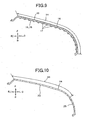
- a protrusion 15 is formed in the middle of the lamp lens 14 in the vertical direction.
- the protrusion 15 is arranged in the window 10.
- the shape of the protrusion 15 is, as shown in Figs. 1, 6, and 7, along the shape of the mirror housing 4. As a result, the outer surface of the protrusion 15 and the outer surface of the mirror housing 4 become substantially flush.
- the rear face of a belt-like flexible substrate 16 made of a glass epoxy resin or the like is secured on the inner face (a face opposite to the lamp chamber 12) of the protrusion 15, along the cross sectional shape of the lamp lens 14.
- a plurality of LEDs 17 as a light source is surface-mounted in an array on the surface of the flexible substrate 16 substantially at equal intervals.
- Surface mounting of the LED 17 is realized by bonding a chip of the LED 17 made of an epoxy resin or the like on the surface of the flexible substrate 16, covering the chip with a transparent resin lens, and securing the lens on the surface of the flexible substrate 16.
- the LED 17 is mainly for emitting ornamental light.
- a light non-transmitting portion 18 as a shielding portion is provided at the position of the protrusion 15 where the flexible substrate 16 and the LED 17 are secured.
- the light non-transmitting portion 18 is obtained by applying aluminum plating, aluminum evaporation, silver plating, or the like.
- the light non-transmitting portion 18 is for concealing the LED 17 as the light source.
- the aluminum plating, aluminum evaporation, or silver plating applied to the light non-transmitting portion 18 is indicated by thick solid line in Fig. 7, together with a range 34 indicated by arrow in Fig. 7 and the flexible substrate 16 in Fig. 9, and is provided in the range 34 indicated by arrow in Fig. 9.
- An ornamental prism group 19 is provided at a position corresponding to the light non-transmitting portion 18 of the outer surface of the protrusion 15.
- the prism group 19 is indicated by dot chain line in the figure.
- the light non-transmitting portion 18 and the prism group 19 are slenderized in the horizontal direction, substantially in the middle in the vertical direction of the protrusion 15, which is slenderized in the horizontal direction.
- a light transmitting portion 20 is provided at positions in the protrusion 15, other than the positions where the flexible substrate 16, the LED 17, the light non-transmitting portion light 18, and the prism group 19 are provided. Ornamentation is applied to the light transmitting portion 20.
- the ornamentation for the light transmitting portion 20 includes, for example, an ornamental color such as the color of the light-transmitting lamp lens 14, ornamental smoking (semitransparent color), an ornamental horning, and the like.
- the ornamental color for the light transmitting portion 20, ornamental smoking, the ornamental horning, or the like is provided in the range other than the light non-transmitting portion 18, and in a range 35 indicated by arrow in Fig. 10.
- the ornamental smoking for the light transmitting portion 20, the ornamental horning, and the like are applied, for example, after masking the portion corresponding to the light non-transmitting portion 18.
- the light transmitting portion 20 is slenderized in the horizontal direction above and below the light non-transmitting portion 18 and the prism group 19 in the protrusion 15 of the lamp lens 14, which is slenderized in the horizontal direction.
- a reflection surface 21 is provided on the inner surface (a surface opposite to the lamp chamber 12) of the lamp housing 13 in the vertically middle portion.
- the reflection surface 21 is for reflecting the light from the LED 17 and irradiating the light to the outside.
- the reflection surface 21 is set, as shown in Fig. 1, corresponding to each LED 17.
- the reflection surface 21 is formed of, as shown in Figs. 1, 7, and 8, a flat reflection surface 22 in a pyramid shape (square quadrangular pyramid shape) and a curved reflection surface 23 of a paraboloid of revolution, with the emission point of the LED being a substantial focal point.
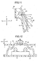
- Two LEDs 24 are provided in the lamp unit 11 for the turn lamp function.
- the LED 24 is arranged, as shown in Figs. 11 and 12, in a lamp chamber 12, at a wrap-around portion from the front side F to the outside O.
- a prism 25 that controls the light distribution of the light from the LED 24 is provided at a portion on the outside O of the lamp lens 14.
- the ornamental smoking, the ornamental horning, or the like for the light transmitting portion 20 is not applied to a portion of the lamp lens 14 where the prism 25 for controlling the light distribution is provided.
- the lamp unit 11 has a unit structure including the lamp housing 13, the lamp lens 14, the LEDs 17, the light non-transmitting portions 18, the light transmitting portions 20, the reflection surfaces 21, and the LEDs 24.
- the LEDs 17 and 24 When the LEDs 17 and 24 are turned off and does not emit light, these look like as shown in Fig. 4. At this time, the light non-transmitting portion 18 applied with the prism group 19 looks like emitting light, and the light transmitting portion 20 applied with the ornamental smoking or the like looks like not emitting light. Further, the LEDs 17 and 24 are concealed by the light transmitting portion 20 and are not visible.
- the LEDs 17 are turned on so as to emit light.
- the light from the LEDs 17 is reflected by the flat reflection surfaces 22 and the curved reflection surfaces 23 of the reflection surface 21.
- the reflected light cannot transmit through the light non-transmitting portion 18, and hence, the light non-transmitting portion 18 dose not emit light.
- the reflected light transmits through the light transmitting portion 20, and hence, the light transmitting portion 20 emits light over the whole surface, and looks like as shown in Fig. 5. That is, the two up and down rays of light of the ornament light slenderized in the horizontal direction are not visible.
- the light from the LED 17 is once reflected by the flat reflection surface 22 and the curved reflection surface 23 of the reflection surface 21 and indirectly irradiated to the outside.
- a plurality of short straight lines drawn in the vertical direction from the up and down horizontal line of the lamp unit 11 indicate the state such that the light transmitting portion 20 is emitting light over the whole surface.
- the LEDs 24 are also turned on so as to emit light. Then the light from the LEDs 24 transmits through the prism 25 for controlling the light distribution of the lamp lens 14, as shown by arrow of solid line in Fig. 11, and the light distribution thereof is controlled within a predetermined range and irradiated to the outside.
- the range of the light irradiated from the LEDs 24 is the hatched area shown in Figs. 2 and 3. ⁇ 1 is 60 degrees, ⁇ 2 is 5 degrees with respect to the vertical axis V-V in the traveling direction of the car C, and ⁇ 3 is 15 degrees with respect to the horizontal axis H-H of the car C in Fig. 3.
- an LED other than the LEDs that emit red light for example, an LED that emits yellow, amber, or white light is used.
- a colored lens of a color other than red for example, a colored lens of yellow or amber is used for the lamp lens 14.
- the door mirror 1 uses the lamp unit 11 that once reflects the light from the LEDs 17 by the flat reflection surfaces 22 and the curved reflection surfaces 23 of the reflection surface 21, and indirectly irradiates the reflected light from the light transmitting portion 20 of the lamp lens 14 to the outside.
- the indirectly irradiating type lamp unit 11 the light transmitting portion 20 of the lamp lens 14 emits light substantially over the whole surface and soft light can be obtained, as compared to the lamp unit of a directly irradiating type used for the conventional vehicle outside-mirror unit.
- the door mirror 1 can improve the appearance when the LEDs 17 is turned on.
- the light from the LEDs 17 fixed to the light non-transmitting portion 18 of the lamp lens 14 is reflected by the reflection surface 21 provided in the lamp housing 13 opposite to the lamp lens 14 and irradiated from the light transmitting portion 20 of the lamp lens 14 to the outside, the light from the LEDs 17 can be indirectly irradiated to the outside reliably.
- the door mirror 1 the position of the lamp lens 14 where the LED 17 is secured is in the light non-transmitting portion 18, even if the inside of the lamp chamber 12 is visible from outside through the lamp lens 14, the flexible substrate 16 and the LEDs 17 are concealed by the light non-transmitting portion 18 and are not visible. As a result, the door mirror 1 can improve the appearance when the LEDs 17 is turned off.
- the light non-transmitting portion 18 and the light transmitting portion 20 are provided on the lamp lens 14, the prism group 19 is provided on the light non-transmitting portion 18, and ornamental smoking or the like is applied to the light transmitting portion 20. Therefore, in the door mirror 1, when the LEDs 17 are turned off and does not emit light, the light non-transmitting portion 18 provided with the prism group 19 looks like shining, and the light transmitting portion 20 provided with ornamentation such as smoking looks like not shining.
- the door mirror 1 can improve the design effect of the lamp unit of the vehicle outside-mirror unit, by the unexpectedness between the expectation of irradiation by the light non-transmitting portion 18 in the lamp lens 14 when the LEDs 17 is turned off and not emitting light, and the actual irradiation by the light transmitting portion 20 in the lamp lens 14 when the LEDs 17 is turned on and emitting light.
- the ornamental prism group 19 is provided on the light non-transmitting portion 18, and ornamental smoking is applied to the light transmitting portion 20, the design effect due to the unexpectedness is large.
- the ornamental prism group 19 and ornamental smoking may not be provided on the light non-transmitting portion 18 and the light transmitting portion 20.
- the lamp unit 11 since the lamp unit has a unit structure as the lamp unit 11, if the window 10 is formed in the mirror housing 4, the lamp unit 11 can be applied to an existing vehicle outside-mirror unit. Further, since the lamp unit can be applied to various vehicle outside-mirror units having a shape of the mirror housing approximate or similar to the one in the present invention. As a result, versatility and common feature can be obtained for the lamp unit 11.
- the lamp unit 11 can be made thin.
- the door mirror 1 is suitable for the vehicle outside-mirror unit having a limited space for installing the lamp unit, and the lamp unit 11 can follow the outer shape of the mirror housing 4 without protruding from the mirror housing 4.
- the LEDs 17 can be arranged along the outside surface of the lamp lens 14 by the flexible substrate 16.
- the complex reflection surface 21 including the flat reflection surfaces 22 and the curved reflection surfaces 23 is provided corresponding to each of the LEDs 17. Therefore, the light from the LEDs 17 can be effectively reflected, and wide light emission can be obtained in the light transmitting portion 20.
- the door mirror 1 Since the door mirror 1 is provided with the LEDs 24 for the turn lamp function, the door mirror 1 can also have the turn lamp function.
- the mirror unit 7 As shown in Fig. 1, however, the mirror unit 7 is tiltable in the door mirror 1. Therefore, it is necessary to arrange the lighting unit (LEDs 24 and the like) in the state protruding from the wrap-around portion toward the outside O, so as not to interrupt tilting of the mirror unit 7.
- the lighting unit protrudes from the outer surface (design) of the door mirror 1 (mirror housing 4), which is not desirable in view of appearance.
- the prism 25 for controlling the light distribution is provided on the lamp lens 14, the LEDs 24 can be arranged at a position on the front side F, in the wrap-around portion of the mirror housing 4, so as not to interrupt tilting of the mirror unit 7, and the lamp lens 14 can follow the shape of the outer surface (design) of the mirror housing 4.
- the door mirror 1 can sufficiently satisfy the light distribution range for the turn lamp function.
- Figs. 13 to 16 depict a second embodiment of the vehicle outside-mirror unit having the lamp unit according to the present invention.
- Like reference signs as in Figs. 1 to 12 designate like parts throughout Figs. 13 to 16.
- the reflection surface 26 includes an inverted V-shape flat reflection surface 27 and a V-shape flat reflection surface 28 provided along the row of a plurality of LEDs 17, and a curved reflection surface 29 of a paraboloid of revolution, with the emission point of the LED 17 being a substantial focal point.
- the inverted V-shape flat reflection surface 27 reflects light from the LED 17 toward the curved reflection surface 29 as reflected light L1.
- the V-shape flat reflection surface 28 reflects light from the LED 17 outward as reflected light L2.
- the curved reflection surface 29 reflects light from the LED 17 outward as reflected light L3 of parallel light, and reflects light from the inverted V-shape flat reflection surface 27 outward as reflected light L4.
- the door mirror 1A in the second embodiment can achieve the similar action and effect to those of the door mirror 1 in the first embodiment. Further, the door mirror 1A can use the light from the LED 17 effectively, by composite reflection of the reflected light L1 from the inverted V-shape flat reflection surface 27, the reflected light L2 from the V-shape flat reflection surface 28, and the reflected light L3 and L4 from the curved reflection surface 29.
- the optical axis ZB of the curved reflection surface 29 corresponding to the back side B of the wrap-around portion of the mirror housing 4 is directed toward the back side B with respect to the optical axis ZF of another curved reflection surface 29 corresponding to the front side F of the mirror housing 4.
- the ornamental LEDs 17 can achieve the turn lamp function.
- Fig. 17 depicts a modification of the second embodiment.
- Like reference signs as in Figs. 1 to 16 designate like parts in the figure.
- an inner lens 30 is arranged in the lamp chamber 12, with respect to the door mirror 1A in the second embodiment, and the LED 17 is fixed to the inner lens 30 via the flexible substrate 16.
- the door mirror 1B can achieve the action and effect substantially similar to those of the door mirrors 1 and 1A in the first and the second embodiments.
- the inner lens 30 and the outer lens (lamp lens 14)
- the visible color of the outer lens at the time of turning off the LED 17 and the visible color of the outer lens at the time of turning on the LED 17 can be changed.
- Fig. 18 depicts a third embodiment of the vehicle outside-mirror unit including the lamp unit according to the present invention.
- Like reference signs as in Figs. 1 to 17 designate like parts in the figure.
- the LED 17 is fixed to the upper part (or the lower part) of a protrusion 15 of the lamp lens 14 via the flexible substrate 16, with respect to the door mirrors 1, 1A, and 1B in the first and the second embodiments and the modification.
- a curved reflection surface 31 for example, on one side of the paraboloid of revolution, is provided in the lamp housing 13 corresponding to each of the LEDs 17.
- a shielding portion 33 for concealing the LED 17 is provided at an edge of the window 10 in the mirror housing 4, and at a position of the lamp lens 14 corresponding to a position where the LED 17 is fixed.
- the door mirror 1C in the third embodiment can achieve the action and effect similar to those of the door mirrors 1, 1A, and 1B in the first and the second embodiments and the modification.
- the flexible substrate 16 and the LED 17 are concealed by the shielding portion 33, the presence of the flexible substrate 16 and the LED 17 can be concealed without providing the light non-transmitting portion applied with the aluminum plating, aluminum evaporation, or silver plating, on the lamp lens 14.
- Fig. 19 depicts a fourth embodiment of the vehicle outside-mirror unit including the lamp unit according to the present invention.
- Like reference signs as in Figs. 1 to 18 designate like parts in the figure.
- the LED 17 is fixed to both the upper part and the lower part of the protrusion 15 of the lamp lens 14 via the flexible substrate 16, with respect to the door mirrors 1, 1A, 1B, and 1C in the first, the second, and the third embodiments and the modification.
- curved reflection surfaces 32 for example, on both sides of the paraboloid of revolution, are provided in the lamp housing 13 corresponding to each of the LEDs 17.
- the shielding portion 33 for concealing the LED 17 is provided at an edge of the window 10 of the mirror housing 4, and at a portion of the lamp lens 14 corresponding to a portion where the LED 17 is fixed.
- the door mirror 1D in the fourth embodiment can achieve the action and effect similar to those of the door mirrors 1, 1A, 1B, and 1C in the first, the second, and the third embodiments and the modification.
- the flexible substrate 16 and the LED 17 are concealed by the shielding portion 33, the presence of the flexible substrate 16 and the LED 17 can be concealed without providing the light non-transmitting portion applied with the aluminum plating, aluminum evaporation, or silver plating on the lamp lens 14.
- the door mirror has been explained.
- the mirror may not be the door mirror, and may be other vehicle outside-mirror units, for example, a fender mirror, a truck mirror, or the like.
- the mirror housing and the lamp housing 13 in the lamp unit 11 having the unit structure are formed of separate bodies.
- the lamp unit 11 may not have the unit structure, and the mirror housing may also function as the lamp housing.
- the portion of the mirror housing, which serves as the lamp housing the lamp lens and the lamp chamber are separated as in the lamp housing, and a reflection surface for reflecting the light from the light source fixed to the lamp lens is provided therein.
Applications Claiming Priority (2)
| Application Number | Priority Date | Filing Date | Title |
|---|---|---|---|
| JP2003427573A JP2005190716A (ja) | 2003-12-24 | 2003-12-24 | 車両用アウトサイドミラー装置 |
| JP2003427573 | 2003-12-24 |
Publications (2)
| Publication Number | Publication Date |
|---|---|
| EP1547863A1 true EP1547863A1 (fr) | 2005-06-29 |
| EP1547863B1 EP1547863B1 (fr) | 2007-10-31 |
Family
ID=34544970
Family Applications (1)
| Application Number | Title | Priority Date | Filing Date |
|---|---|---|---|
| EP04029704A Expired - Fee Related EP1547863B1 (fr) | 2003-12-24 | 2004-12-15 | Rétroviseur extérieur pour véhicule comprenant un dispositif d'éclairage |
Country Status (6)
| Country | Link |
|---|---|
| US (1) | US7134772B2 (fr) |
| EP (1) | EP1547863B1 (fr) |
| JP (1) | JP2005190716A (fr) |
| KR (1) | KR100603825B1 (fr) |
| CN (1) | CN100345706C (fr) |
| DE (1) | DE602004009748T2 (fr) |
Families Citing this family (18)
| Publication number | Priority date | Publication date | Assignee | Title |
|---|---|---|---|---|
| JP4433789B2 (ja) * | 2003-12-24 | 2010-03-17 | 市光工業株式会社 | 車両用アウトサイドミラー装置 |
| US8305225B2 (en) * | 2005-02-14 | 2012-11-06 | Truck-Lite Co., Llc | LED strip light lamp assembly |
| KR100715896B1 (ko) * | 2005-12-08 | 2007-05-08 | 현대자동차주식회사 | 아웃사이드 미러의 턴 시그널 램프 |
| JP2008097848A (ja) * | 2006-10-06 | 2008-04-24 | Ichikoh Ind Ltd | 車両用灯具 |
| JP4631838B2 (ja) * | 2006-10-20 | 2011-02-16 | 市光工業株式会社 | 車両用灯具 |
| JP4631840B2 (ja) * | 2006-11-02 | 2011-02-16 | 市光工業株式会社 | 車両用灯具 |
| JP4850743B2 (ja) * | 2007-02-13 | 2012-01-11 | 株式会社小糸製作所 | 車両用前照灯 |
| JP5032163B2 (ja) * | 2007-03-12 | 2012-09-26 | 株式会社ミツバ | 車両用ランプ |
| JP5075572B2 (ja) * | 2007-10-18 | 2012-11-21 | 株式会社ミツバ | ドアミラー |
| JP5425443B2 (ja) * | 2008-10-31 | 2014-02-26 | 株式会社ミツバ | 車両用ランプ |
| EP2340967B2 (fr) * | 2009-12-29 | 2016-09-14 | SMR Patents S.à.r.l. | Module lumineux indicateur de virage pour ensemble de miroir de véhicule et ensemble de miroir de véhicule comprenant le module lumineux indicateur de virage |
| WO2012133147A1 (fr) * | 2011-03-30 | 2012-10-04 | 株式会社ミツバ | Lampe de clignotant pour un rétroviseur de porte |
| JP5711600B2 (ja) * | 2011-04-27 | 2015-05-07 | 株式会社小糸製作所 | 車両用灯具 |
| US9117991B1 (en) * | 2012-02-10 | 2015-08-25 | Flextronics Ap, Llc | Use of flexible circuits incorporating a heat spreading layer and the rigidizing specific areas within such a construction by creating stiffening structures within said circuits by either folding, bending, forming or combinations thereof |
| JP6237987B2 (ja) * | 2013-07-12 | 2017-11-29 | オムロン株式会社 | リレー |
| JP6234157B2 (ja) * | 2013-10-17 | 2017-11-22 | 株式会社小糸製作所 | 車両用灯具 |
| JP6293604B2 (ja) * | 2014-07-28 | 2018-03-14 | 株式会社村上開明堂 | ランプ付き車両用アウターミラー |
| CA3035031A1 (fr) * | 2018-10-22 | 2020-04-22 | David Andrew Trytko | Accessoires de securite de multiple usage |
Citations (4)
| Publication number | Priority date | Publication date | Assignee | Title |
|---|---|---|---|---|
| US20010010633A1 (en) * | 2000-01-27 | 2001-08-02 | Reitter & Schefenacker Gmbh & Co. Kg | Exterior rearview mirror for vehicles, in particular, for motor vehicles |
| US6271750B1 (en) * | 1999-07-19 | 2001-08-07 | Fer Fahrzeugelektrik Gmbh | Side flashing lamp |
| EP1442930A2 (fr) * | 2003-02-03 | 2004-08-04 | Ichikoh Industries, Ltd. | Rétroviseur extérieur avec lumière |
| EP1442934A1 (fr) * | 2003-01-30 | 2004-08-04 | Ichikoh Industries, Ltd. | Rétroviseur extérieur pour véhicules |
Family Cites Families (15)
| Publication number | Priority date | Publication date | Assignee | Title |
|---|---|---|---|---|
| CN85105908A (zh) * | 1985-08-01 | 1986-07-23 | 邹自正 | 带有照明灯的汽车外后视镜 |
| JPH08142745A (ja) | 1994-11-17 | 1996-06-04 | Kyowa Shatai:Kk | 自動車の補助フラッシャ−ランプ |
| DE29804489U1 (de) * | 1998-03-13 | 1998-05-20 | Reitter & Schefenacker Gmbh | Außenrückblickspiegel für Fahrzeuge, vorzugsweise für Kraftfahrzeuge |
| DE19828253B4 (de) * | 1998-06-25 | 2006-04-06 | Daimlerchrysler Ag | Außenrückblickspiegel |
| JP2000025519A (ja) * | 1998-07-14 | 2000-01-25 | Kayama Yuki | 車両用サイドミラー |
| US6079858A (en) * | 1998-08-17 | 2000-06-27 | Lear Automotive Dearborn, Inc. | Side view mirror with detachable flashlight |
| KR20000017474U (ko) * | 1999-02-26 | 2000-09-25 | 이문성 | 보조표시등을 설치한 자동차용 백미러 |
| DE10025810B4 (de) | 2000-05-24 | 2014-01-23 | SMR Patents S.à.r.l. | Leuchteneinheit, insbesondere für Außenrückblickspiegel von Fahrzeugen, vorzugsweise von Kraftfahrzeugen |
| JP4038975B2 (ja) | 2000-09-21 | 2008-01-30 | 市光工業株式会社 | 車両用ドアミラー |
| US6637917B2 (en) * | 2000-10-04 | 2003-10-28 | Fer Fahrzeugelektrik Gmbh | Side flashing lamp |
| JP2002362222A (ja) | 2001-05-31 | 2002-12-18 | Tokai Rika Co Ltd | アウタミラーのターンシグナル付きバイザカバー構造 |
| KR100439822B1 (ko) * | 2001-09-27 | 2004-07-12 | 현대자동차주식회사 | 자동차용 사이드 미러 램프 체결구조 |
| US6769798B2 (en) * | 2002-04-11 | 2004-08-03 | E'sam Co.,. Ltd. | Side mirror cover and cover lamp to be used therefor |
| US6749325B2 (en) * | 2002-10-29 | 2004-06-15 | K.W. Muth Company | Signaling assembly |
| US6932497B1 (en) * | 2003-12-17 | 2005-08-23 | Jean-San Huang | Signal light and rear-view mirror arrangement |
-
2003
- 2003-12-24 JP JP2003427573A patent/JP2005190716A/ja active Pending
-
2004
- 2004-12-15 EP EP04029704A patent/EP1547863B1/fr not_active Expired - Fee Related
- 2004-12-15 DE DE602004009748T patent/DE602004009748T2/de active Active
- 2004-12-17 KR KR1020040107899A patent/KR100603825B1/ko not_active IP Right Cessation
- 2004-12-21 US US11/017,234 patent/US7134772B2/en not_active Expired - Fee Related
- 2004-12-22 CN CNB2004101017913A patent/CN100345706C/zh not_active Expired - Fee Related
Patent Citations (4)
| Publication number | Priority date | Publication date | Assignee | Title |
|---|---|---|---|---|
| US6271750B1 (en) * | 1999-07-19 | 2001-08-07 | Fer Fahrzeugelektrik Gmbh | Side flashing lamp |
| US20010010633A1 (en) * | 2000-01-27 | 2001-08-02 | Reitter & Schefenacker Gmbh & Co. Kg | Exterior rearview mirror for vehicles, in particular, for motor vehicles |
| EP1442934A1 (fr) * | 2003-01-30 | 2004-08-04 | Ichikoh Industries, Ltd. | Rétroviseur extérieur pour véhicules |
| EP1442930A2 (fr) * | 2003-02-03 | 2004-08-04 | Ichikoh Industries, Ltd. | Rétroviseur extérieur avec lumière |
Also Published As
| Publication number | Publication date |
|---|---|
| KR20050065324A (ko) | 2005-06-29 |
| EP1547863B1 (fr) | 2007-10-31 |
| CN100345706C (zh) | 2007-10-31 |
| KR100603825B1 (ko) | 2006-07-24 |
| US7134772B2 (en) | 2006-11-14 |
| DE602004009748T2 (de) | 2008-03-06 |
| JP2005190716A (ja) | 2005-07-14 |
| DE602004009748D1 (de) | 2007-12-13 |
| CN1636795A (zh) | 2005-07-13 |
| US20050146886A1 (en) | 2005-07-07 |
Similar Documents
| Publication | Publication Date | Title |
|---|---|---|
| EP1547863B1 (fr) | Rétroviseur extérieur pour véhicule comprenant un dispositif d'éclairage | |
| US7163322B2 (en) | Illumination device for license plate | |
| US6752522B2 (en) | Optical or styling component for a lighting or indicator device for a motor vehicle | |
| JP3544010B2 (ja) | 車両用灯火器 | |
| US4949226A (en) | Projector-type lighting device of expanded outline appearance for use as a vehicular headlamp or the like | |
| US7347598B2 (en) | Outside mirror apparatus for vehicle and illuminating unit for outside mirror apparatus | |
| US6951414B2 (en) | Vehicular lamp | |
| US7140757B2 (en) | Vehicle mirror assembly that includes light unit | |
| US20080180965A1 (en) | Vehicular Lamp | |
| JP2007532389A (ja) | 特に自動車とする車両のための車外バックミラー | |
| US5029053A (en) | Rear illumination license plate frame | |
| US7513665B2 (en) | Headlamp module and headlamp assembly with internally reflecting translucent member | |
| JP2003051206A (ja) | 自動車用の照明及び表示装置 | |
| JP3337125B2 (ja) | リフレックスリフレクタ付車両用灯具 | |
| JPS6333878A (ja) | 発光ダイオ−ド構造物 | |
| US11498480B2 (en) | Illuminating device for vehicle ceiling lamp | |
| JP2011018563A (ja) | 車両用灯具 | |
| CN220540932U (zh) | 车辆用灯具 | |
| US11754251B2 (en) | Vehicular lamp | |
| JP2002289003A (ja) | 車輌用警告灯 | |
| JP2001216813A (ja) | 車両用灯具 | |
| CN116457608A (zh) | 车辆用灯具 | |
| JP2011018562A (ja) | 車両用灯具 | |
| JPH11111014A (ja) | ランプ | |
| JP2005174633A (ja) | 車両用灯具 |
Legal Events
| Date | Code | Title | Description |
|---|---|---|---|
| PUAI | Public reference made under article 153(3) epc to a published international application that has entered the european phase |
Free format text: ORIGINAL CODE: 0009012 |
|
| AK | Designated contracting states |
Kind code of ref document: A1 Designated state(s): AT BE BG CH CY CZ DE DK EE ES FI FR GB GR HU IE IS IT LI LT LU MC NL PL PT RO SE SI SK TR |
|
| AX | Request for extension of the european patent |
Extension state: AL BA HR LV MK YU |
|
| 17P | Request for examination filed |
Effective date: 20050826 |
|
| AKX | Designation fees paid |
Designated state(s): DE FR GB |
|
| GRAP | Despatch of communication of intention to grant a patent |
Free format text: ORIGINAL CODE: EPIDOSNIGR1 |
|
| RIN1 | Information on inventor provided before grant (corrected) |
Inventor name: IWATA, CHIHARU Inventor name: FURUYA, KAORI |
|
| GRAS | Grant fee paid |
Free format text: ORIGINAL CODE: EPIDOSNIGR3 |
|
| GRAA | (expected) grant |
Free format text: ORIGINAL CODE: 0009210 |
|
| AK | Designated contracting states |
Kind code of ref document: B1 Designated state(s): DE FR GB |
|
| REG | Reference to a national code |
Ref country code: GB Ref legal event code: FG4D |
|
| REF | Corresponds to: |
Ref document number: 602004009748 Country of ref document: DE Date of ref document: 20071213 Kind code of ref document: P |
|
| ET | Fr: translation filed | ||
| PLBE | No opposition filed within time limit |
Free format text: ORIGINAL CODE: 0009261 |
|
| STAA | Information on the status of an ep patent application or granted ep patent |
Free format text: STATUS: NO OPPOSITION FILED WITHIN TIME LIMIT |
|
| 26N | No opposition filed |
Effective date: 20080801 |
|
| PGFP | Annual fee paid to national office [announced via postgrant information from national office to epo] |
Ref country code: FR Payment date: 20091221 Year of fee payment: 6 Ref country code: GB Payment date: 20091209 Year of fee payment: 6 |
|
| PGFP | Annual fee paid to national office [announced via postgrant information from national office to epo] |
Ref country code: DE Payment date: 20091222 Year of fee payment: 6 |
|
| GBPC | Gb: european patent ceased through non-payment of renewal fee |
Effective date: 20101215 |
|
| REG | Reference to a national code |
Ref country code: FR Ref legal event code: ST Effective date: 20110831 |
|
| PG25 | Lapsed in a contracting state [announced via postgrant information from national office to epo] |
Ref country code: FR Free format text: LAPSE BECAUSE OF NON-PAYMENT OF DUE FEES Effective date: 20110103 |
|
| REG | Reference to a national code |
Ref country code: DE Ref legal event code: R119 Ref document number: 602004009748 Country of ref document: DE Effective date: 20110701 |
|
| PG25 | Lapsed in a contracting state [announced via postgrant information from national office to epo] |
Ref country code: GB Free format text: LAPSE BECAUSE OF NON-PAYMENT OF DUE FEES Effective date: 20101215 Ref country code: DE Free format text: LAPSE BECAUSE OF NON-PAYMENT OF DUE FEES Effective date: 20110701 |