EP1541825A2 - Doppelwandiges Endrohr einer Kraftfahrzeugabgasanlage - Google Patents
Doppelwandiges Endrohr einer Kraftfahrzeugabgasanlage Download PDFInfo
- Publication number
- EP1541825A2 EP1541825A2 EP05005353A EP05005353A EP1541825A2 EP 1541825 A2 EP1541825 A2 EP 1541825A2 EP 05005353 A EP05005353 A EP 05005353A EP 05005353 A EP05005353 A EP 05005353A EP 1541825 A2 EP1541825 A2 EP 1541825A2
- Authority
- EP
- European Patent Office
- Prior art keywords
- outer shell
- inner shell
- tailpipe
- shell
- support
- Prior art date
- Legal status (The legal status is an assumption and is not a legal conclusion. Google has not performed a legal analysis and makes no representation as to the accuracy of the status listed.)
- Withdrawn
Links
Images

Classifications
-
- F—MECHANICAL ENGINEERING; LIGHTING; HEATING; WEAPONS; BLASTING
- F01—MACHINES OR ENGINES IN GENERAL; ENGINE PLANTS IN GENERAL; STEAM ENGINES
- F01N—GAS-FLOW SILENCERS OR EXHAUST APPARATUS FOR MACHINES OR ENGINES IN GENERAL; GAS-FLOW SILENCERS OR EXHAUST APPARATUS FOR INTERNAL-COMBUSTION ENGINES
- F01N13/00—Exhaust or silencing apparatus characterised by constructional features
- F01N13/20—Exhaust or silencing apparatus characterised by constructional features having flared outlets, e.g. of fish-tail shape
-
- F—MECHANICAL ENGINEERING; LIGHTING; HEATING; WEAPONS; BLASTING
- F01—MACHINES OR ENGINES IN GENERAL; ENGINE PLANTS IN GENERAL; STEAM ENGINES
- F01N—GAS-FLOW SILENCERS OR EXHAUST APPARATUS FOR MACHINES OR ENGINES IN GENERAL; GAS-FLOW SILENCERS OR EXHAUST APPARATUS FOR INTERNAL-COMBUSTION ENGINES
- F01N13/00—Exhaust or silencing apparatus characterised by constructional features
- F01N13/08—Other arrangements or adaptations of exhaust conduits
- F01N13/082—Other arrangements or adaptations of exhaust conduits of tailpipe, e.g. with means for mixing air with exhaust for exhaust cooling, dilution or evacuation
Definitions
- the invention relates to a double-walled tailpipe Automotive exhaust system according to the preamble of the claim 1.
- Double-walled tailpipes of the aforementioned type are known from DE 196 51 608 C2 and the corresponding EP 0 848 144 A1.
- Inner shell and outer shell are at the outlet end of the Tailpipe connected to each other, wherein the inner shell in the bent edge of the outer shell engages and with her exit end opposite the bent part of the Outer shell is welded. Otherwise, inner shell and Outer shell to each other without contact and it is about the Inner shell, the tailpipe attached to the exhaust pipe. Between Inner shell and outer shell is thus a circumferential Air gap given.
- a double-walled tailpipe is intended by the invention of the type mentioned in the above developed be that despite simplified manufacturing an improved Cooling effect achieved and thus a start-up of the tailpipe - at least in the visible range - the outer shell as a rule is avoided.
- According to the invention opens the air gap between the inner shell and outer shell of the tailpipe is formed at the exit end of the tailpipe.
- Inner shell and outer shell are preferably by a Support against each other supported, which of air passage openings is interspersed.
- the support preferably designed so that they lie in the air gap or on the air gap opening air inlet openings having.
- connection between inner and outer tube is preferably from the outlet pipe projecting beyond the exhaust pipe
- the end area of the tailpipe is laid in an area in the inner and outer shell in overlap to the exhaust pipe lie and in which the inner shell against the exhaust pipe is supported.
- a preferred and manufacturing technology easy to control Solution is that the inner shell, relative to the direction of flow, upstream of her Connection and support against the exhaust pipe, a radial has a widened and openwork waistband, the radially outward against the inner wall of the outer shell supported.
- This covenant can be used as a ring collar with appropriate Breakthroughs, but preferably by in the circumferential direction with Distance from each other lying tabs may be formed, and has preferably in the contour of the outer shell adapted Attachment section, so an angled end portion, at one the radial distance between inner shell and outer shell bridging support portion followed.
- an approximately Z-shaped contour wherein the outer leg of the Z forms the attachment portion, the Bridge of Z the support section and the inner leg of the Z-section formed by the area of the inner shell, which is pushed onto the exhaust pipe, according to the invention limits the axial length of the overlap area thereby may be that the inner shell, for example, by appropriate Staging or the like is associated with a stop.
- the tabs can also have a have bent-back end portion, so that they are in Approach U-shaped, between exhaust pipe and outer shell form lying supports, the free leg part is supported on the exhaust pipe.
- This can also be a simple bracket can be realized, which is a certain Movement allows.
- the coverage area between inner shell and exhaust pipe relatively be kept short, if in a further embodiment of the Invention the outer shell at least in a partial area the Inner shell over which to support the inner shell against the outer shell required extent beyond axial upstream overlaps and if in this sub-area an additional fixation, for example, by a screw of the outer shell takes place opposite the exhaust pipe.
- Such support can be placed in an area that is the field of view is normally removed, such as the bottom be associated with the tailpipe.
- a corresponding fuse pushed onto the exhaust pipe Inner shell but also be achieved in that Area of overlap of inner shell and exhaust pipe one appropriate fuse arrangement is provided, for example by one or more clamping screws, at least the inner shell passing through against the exhaust pipe for support to bring.
- a corresponding Spannverschraubung also in the area of the support of the Inner shell provided against the outer shell serving federal be.
- the inner shell is non-contact to the outer shell and ends especially with distance, preferably with a small axial distance to the downstream radial inner end of the Outer shell.
- the end of the outer shell is preferably rounded trained, so for example, rolled or crimped.
- the solution according to the invention can also be used in particular realize a relatively short inner shell, wherein over the inner shell protruding extensions of the outer shell also be used or trained to that effect can be that a funnel-like detection of the air gap supplied air flow results.
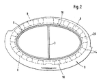
- the figures show a double-walled tailpipe 1 for a Exhaust pipe 2 a not further shown exhaust system a motor vehicle, wherein in the embodiment of the Exhaust pipe 2 in the exit-side end region oval cross-section has and is provided with a partition wall 3.
- this at least optically two-lobe design is by way of example, and the invention is equally as follows Exhaust pipes of round cross section or other, more common Use cross sections, in single or multi-flow design.
- the double-walled tailpipe has an outer shell 4 and a Inner shell 5 on, and is over its end on the Exhaust pipe 2 retractable inner shell 5 with the exhaust pipe. 2 connected, wherein the inner shell 5 carries the outer shell 4.
- the inner shell 5 is, starting from the free end 6 of the exhaust pipe 2, postponed to this, being the Aufschiebeweg in a manner not shown by a stop collar or the like which is limited to the inner periphery of Inner shell 5 may be associated with the corresponding Wegbegrenzung also by individual characteristics or the like can be formed.
- the Aufschiebeweg the inner shell 5 on the exhaust pipe 2 is relatively short and corresponds in the exemplary embodiment about the radial width of the air gap 7, of the inner shell 5 relative to the outer shell. 4 is demarcated. On this air gap 7 open air inlet openings 8, in the radial support 9 of the inner shell 5 are provided opposite the outer shell 4.
- the radial Support 9 is in the embodiment by a the Inner shell 5 enclosing collar 10 is formed, which has an axial Attachment section 11, which at one of the Radial distance of the inner shell 5 to the outer shell 4 bridging Support section 12 connects. In this support section the air inlet openings 8 are provided.
- the collar 10 also formed dissolved be, for example, by circumferentially to each other spaced tabs 20 may be formed, which in cross section have according to Figure 1 Z-shaped contour, wherein the outer Z-leg forms the axial attachment portion 11, the radial web of the Z-section acts as a support portion 12 and the inner leg of these Z-shaped in cross-section Support 9 is formed by the inner shell 5.
- FIG. 1 shows that the length of the axial attachment portion 11th about the width of the seat 17 corresponds, about the Inner shell 5 is held on the exhaust pipe 2.
- the function of the tailpipe 1 according to the invention is independent to realize whether the end cross-section of the double-walled End pipe 1, as in the embodiment, to the axis of the exhaust pipe 2 inclined, whether one to the axis of the exhaust pipe 2 vertical end plane is sought, or whether the Exhaust pipe an obliquely to its axis end cross-section having.
- a Provide screw 13 the axial extension the outer shell 4 is assigned, which is based extends upstream of the exhaust stream 15 and which are preferred is designed as an air scoop. A particularly high air flow is achievable if this air scoop funnel-shaped is.
- the screw 13 may at the exhaust pipe 2 a Attachment bracket 14 to be assigned. Preferably lies the Screw 13 at the bottom of the tail pipe 1, so that she is out of sight. The screw 13 secures both in the axial direction, but also prevents pivoting movements of the tail pipe 1 with respect to the exhaust pipe 2.
- annular gap 18 is located between the outer circumference of the inner shell 5, which is just before the exit end 19 of the Outer shell 4 ends and the outer shell 4. The outer shell.
- the clear width in Figure 1 and based on the drawing plane is labeled 21 - bounding rolled up End portion of the outer shell extends radially to near on the outer circumference of the inner shell 5, so that the annular gap 18 in the form of a Venturi nozzle acting in the exit area a suction effect in connection with a cooling air duct entails, as indicated, an extensive one Shielding of the exhaust stream 15 from the exit end causes the outer shell, so that the outer shell 4 only comparatively is heated slightly and soiling and Discoloration of the outer shell 4 in the visible free End area is counteracted.
- the free cross section of the Annular gap 18 is preferably smaller than the cross section, in particular the inlet cross-section of the air gap 7.
Landscapes
- Engineering & Computer Science (AREA)
- Chemical & Material Sciences (AREA)
- Combustion & Propulsion (AREA)
- Mechanical Engineering (AREA)
- General Engineering & Computer Science (AREA)
- Exhaust Silencers (AREA)
Abstract
Description
- Fig. 1
- einen Schnitt durch ein doppelwandiges Endrohr für ein Abgasrohr einer Abgasanlage eines Kraftfahrzeuges gemäß Linie II-II in Figur 1, teilweise schematisiert, und
- Fig. 2
- eine Ansicht des doppelwandigen Endrohres gemäß Figur 1 in Richtung des Pfeiles II, wiederum teilweise schematisiert dargestellt.
Claims (12)
- Doppelwandiges Endrohr (1) einer Kraftfahrzeugabgasanlage, das endseitig auf ein Abgasrohr (2) der Kraftfahrzeugabgasanlage aufsteckbar ist und eine Innenschale (5) und einer Außenschale (4) aufweist, wobeidadurch gekennzeichnet, dass der Luftspalt (7) am Austrittsende des Endrohrs (1) ausmündet.die Innenschale (5) die Außenschale (4) trägt undInnenschale (5) und Außenschale (4) einen sich über den Umfang erstreckenden durchströmbaren Luftspalt (7) begrenzen,
- Endrohr nach Anspruch 1,
dadurch gekennzeichnet, dass die Innenschale (5) und die Außenschale (4) durch eine Abstützung (9) gegeneinander abgestützt sind, wobei die Abstützung (9) von Luftdurchtrittsöffnungen durchsetzt ist. - Endrohr nach Anspruch 2,
dadurch gekennzeichnet, dass bei aufgestecktem Endrohr (1) die Abstützung (9) an einem Überdeckungsbereich von Innenschale (5) und Abgasrohr (2) angeordnet ist. - Endrohr nach Anspruch 2 oder 3,
dadurch gekennzeichnet, dass bei aufgestecktem Endrohr (1) die Abstützung (9) an einem Endbereich des Abgasrohrs (2) angeordnet ist. - Endrohr nach einem der Ansprüche 2 bis 4,
dadurch gekennzeichnet, dass die Luftdurchtrittsöffnungen auf den Luftspalt (7) ausmündende Lufteintrittsöffnungen (8) bilden. - Endrohr nach einem der Ansprüche 2 bis 5,
dadurch gekennzeichnet, dass die Abstützung (9) durch einen nach radial außen aufgeweiteten, der Innenschale (5) zugeordneten Bund (10) gebildet ist. - Endrohr nach Anspruch 6,
dadurch gekennzeichnet, dass der Bund (10) mehrfach durchbrochen ausgebildet ist. - Endrohr nach Anspruch 6 oder 7,
dadurch gekennzeichnet, dass der Bund (10) durch in Umfangsrichtung zueinander beabstandete Laschen (20) gebildet ist. - Endrohr nach einem der Ansprüche 6 bis 8,
dadurch gekennzeichnet, dass der Bund (10) in einem der Kontur der Außenschale (4) angepassten Befestigungsabschnitt (11) ausläuft. - Endrohr nach einem der Ansprüche 1 bis 9,
dadurch gekennzeichnet, dass die Innenschale (5) austrittsseitig mit axialem Abstand zum Endquerschnitt der Außenschale (4) endet. - Endrohr nach einem der Ansprüche 1 bis 10,
dadurch gekennzeichnet, dass die Außenschale (4) austrittsseitig radial nach innen eingebogen, insbesondere eingerollt ist. - Endrohr nach Anspruch 11,
dadurch gekennzeichnet, dass die Innenschale (5) mit Abstand zum gegen die Außenschale (4) zurückgebogenen Schenkel der Einrollung endet.
Applications Claiming Priority (3)
| Application Number | Priority Date | Filing Date | Title |
|---|---|---|---|
| DE19914426A DE19914426C2 (de) | 1999-03-30 | 1999-03-30 | Doppelwandiges Endrohr für ein Abgasrohr einer Abgasanlage eines Kraftfahrzeuges |
| DE19914426 | 1999-03-30 | ||
| EP00925128A EP1165947B1 (de) | 1999-03-30 | 2000-03-21 | Doppelwandiges endrohr fur ein abgasrohr einer abgasanlage eines kraftfahrzeuges |
Related Parent Applications (1)
| Application Number | Title | Priority Date | Filing Date |
|---|---|---|---|
| EP00925128A Division EP1165947B1 (de) | 1999-03-30 | 2000-03-21 | Doppelwandiges endrohr fur ein abgasrohr einer abgasanlage eines kraftfahrzeuges |
Publications (2)
| Publication Number | Publication Date |
|---|---|
| EP1541825A2 true EP1541825A2 (de) | 2005-06-15 |
| EP1541825A3 EP1541825A3 (de) | 2008-08-13 |
Family
ID=7902960
Family Applications (2)
| Application Number | Title | Priority Date | Filing Date |
|---|---|---|---|
| EP05005353A Withdrawn EP1541825A3 (de) | 1999-03-30 | 2000-03-21 | Doppelwandiges Endrohr einer Kraftfahrzeugabgasanlage |
| EP00925128A Expired - Lifetime EP1165947B1 (de) | 1999-03-30 | 2000-03-21 | Doppelwandiges endrohr fur ein abgasrohr einer abgasanlage eines kraftfahrzeuges |
Family Applications After (1)
| Application Number | Title | Priority Date | Filing Date |
|---|---|---|---|
| EP00925128A Expired - Lifetime EP1165947B1 (de) | 1999-03-30 | 2000-03-21 | Doppelwandiges endrohr fur ein abgasrohr einer abgasanlage eines kraftfahrzeuges |
Country Status (4)
| Country | Link |
|---|---|
| US (1) | US6595318B2 (de) |
| EP (2) | EP1541825A3 (de) |
| DE (2) | DE19914426C2 (de) |
| WO (1) | WO2000060222A1 (de) |
Families Citing this family (41)
| Publication number | Priority date | Publication date | Assignee | Title |
|---|---|---|---|---|
| DE10123567A1 (de) | 2001-05-15 | 2002-11-28 | Porsche Ag | Montierbares Auslassrohr für einen Endschalldämpfer sowie Endschalldämpfer für ein Kraftfahrzeug |
| DE10140435C1 (de) * | 2001-08-17 | 2002-12-12 | Porsche Ag | Abgasanlage mit einer Endrohrvorrichtung |
| DE10205649C1 (de) * | 2002-02-12 | 2003-06-26 | Neef Gmbh & Co Kg | Verfahren zum Herstellen einer auf das Ende eines Kraftfahrzeug-Auspuffrohres aufsetzbaren Blende und eine nach dem Verfahren hergestellte Blende |
| USD468673S1 (en) | 2002-05-22 | 2003-01-14 | American Products Company, Inc. | Illuminated tail pipe extension |
| US20040206573A1 (en) * | 2002-11-27 | 2004-10-21 | Hsu Henry T. H. | Muffler exhaust tip |
| DE10258250A1 (de) * | 2002-12-13 | 2004-07-15 | Dr.Ing.H.C. F. Porsche Ag | Heckverkleidungsteil mit einer daran befestigten Abgasendrohrblende |
| DE10355472B4 (de) * | 2003-11-27 | 2009-06-04 | Daimler Ag | Endrohrblende für eine Abgasanlage eines Kraftfahrzeugs |
| CA2455485A1 (en) * | 2004-01-21 | 2005-07-21 | Lt Exhaust Systems Inc. | Anti-reversion apparatus |
| USD533189S1 (en) * | 2005-04-11 | 2006-12-05 | C & L Performance, Inc. | Inlet pipe |
| USD533191S1 (en) * | 2005-07-19 | 2006-12-05 | C & L Performance, Inc. | Air flow inlet |
| US8001775B2 (en) * | 2005-08-16 | 2011-08-23 | Daimler Trucks North America Llc | Vehicle exhaust dilution and dispersion device |
| USD533878S1 (en) * | 2005-09-01 | 2006-12-19 | C & L Performance, Inc. | Auto intake plenum |
| DE102006020628A1 (de) * | 2006-05-04 | 2007-11-08 | Dr.Ing.H.C. F. Porsche Ag | Abgasanlage |
| DE102006024269A1 (de) * | 2006-05-24 | 2007-11-29 | Dr.Ing.H.C. F. Porsche Ag | Abgasanlage |
| JP4380670B2 (ja) * | 2006-08-10 | 2009-12-09 | トヨタ自動車株式会社 | 自動車後部構造 |
| US7461506B2 (en) * | 2006-09-21 | 2008-12-09 | Gm Global Technology Operations, Inc. | Exhaust gas cooler |
| US7788960B2 (en) * | 2006-10-27 | 2010-09-07 | Cummins Filtration Ip, Inc. | Multi-walled tube and method of manufacture |
| JP2008111356A (ja) * | 2006-10-30 | 2008-05-15 | Yamaha Motor Co Ltd | 自動二輪車の排気装置及び該排気装置を備えた自動二輪車 |
| JP2008111357A (ja) * | 2006-10-30 | 2008-05-15 | Yamaha Motor Co Ltd | 自動二輪車の排気装置 |
| US7604093B2 (en) * | 2006-11-01 | 2009-10-20 | Daimler Trucks North America Llc | Exhaust diffuser for vehicle |
| DE102006051850A1 (de) * | 2006-11-03 | 2008-05-08 | Dr.Ing.H.C. F. Porsche Ag | Endrohrblende |
| US7757482B2 (en) * | 2007-02-21 | 2010-07-20 | Gm Global Technology Operations, Inc. | Variable geometry exhaust cooler |
| US8550122B2 (en) * | 2009-02-25 | 2013-10-08 | Nissan North America, Inc. | Exhaust finisher retention operation |
| US20110192153A1 (en) * | 2010-02-05 | 2011-08-11 | Keith Jonathan Schmidt | Exhaust after treatment assembly |
| KR101209732B1 (ko) * | 2010-09-28 | 2012-12-07 | 현대자동차주식회사 | 차량 배기 파이프용 테일 트림 어셈블리 |
| KR101210047B1 (ko) * | 2010-10-08 | 2012-12-10 | 기아자동차주식회사 | 매연흡착방지 타입 테일트림 |
| US8443928B2 (en) * | 2010-12-03 | 2013-05-21 | Liang Fei Industry Co., Ltd. | Exhaust tail pipe |
| JP5906663B2 (ja) * | 2011-10-27 | 2016-04-20 | スズキ株式会社 | エンジンの排気装置 |
| KR101405197B1 (ko) * | 2012-12-12 | 2014-06-10 | 기아자동차 주식회사 | 소음장치의 테일 파이프 |
| US9523304B2 (en) * | 2013-03-11 | 2016-12-20 | Futaba Industrial Co., Ltd. | Exhaust pipe |
| US9328648B2 (en) * | 2013-04-18 | 2016-05-03 | Ford Global Technologies, Llc | Protective shield to reduce exhaust soot and condensate deposition |
| US9536040B2 (en) | 2013-04-18 | 2017-01-03 | Ford Global Technologies, Llc | Methods for designing an exhaust assembly for a vehicle |
| US9346350B2 (en) * | 2013-04-18 | 2016-05-24 | Ford Global Technologies, Llc | Flush and sub-flush protective shields to reduce exhaust soot and condensate deposition |
| DE102016202056B3 (de) | 2016-02-11 | 2017-03-16 | Cisma Solutions Aps | Abgasauslasssystem für ein Kraftfahrzeug, Kraftfahrzeug mit einem solchen Abgasauslasssystem sowie Verfahren zur Herstellung eines Abgasauslasssystems |
| JP2017160639A (ja) * | 2016-03-08 | 2017-09-14 | 日立建機株式会社 | 作業機械の排気装置 |
| DE102016123114A1 (de) * | 2016-11-30 | 2018-05-30 | Dr. Ing. H.C. F. Porsche Aktiengesellschaft | Fahrzeugkomponente |
| FR3064554B1 (fr) * | 2017-04-04 | 2020-07-24 | Peugeot Citroen Automobiles Sa | Ligne d’echappement de vehicule |
| DE102017214197B4 (de) * | 2017-08-15 | 2021-04-22 | Cisma Solutions Aps | Anordnung und Verfahren zur Abbremsung der Verschiebung einer Endrohrblende |
| DE102018200311A1 (de) * | 2018-01-10 | 2019-07-11 | Bayerische Motoren Werke Aktiengesellschaft | Motorradabgaskrümmer |
| DE102022119557B3 (de) * | 2022-08-04 | 2023-06-29 | Dr. Ing. H.C. F. Porsche Aktiengesellschaft | Abgasendrohranordnung für eine Abgasanlage eines Kraftfahrzeuges |
| MX2024003192A (es) | 2023-03-17 | 2024-09-18 | Polaris Inc | Sistema de aire/escape para un vehiculo. |
Citations (1)
| Publication number | Priority date | Publication date | Assignee | Title |
|---|---|---|---|---|
| EP0848144A1 (de) | 1996-12-12 | 1998-06-17 | Dr.Ing.h.c. F. Porsche Aktiengesellschaft | Endrohr für Abgasrohr einer Abgasanlage eines Kraftfahrzeuges |
Family Cites Families (15)
| Publication number | Priority date | Publication date | Assignee | Title |
|---|---|---|---|---|
| DE7838091U1 (de) * | 1979-07-05 | Hermann J. Schulte Kg, 5750 Menden | Federklemme zur Befestigung von Rohrblenden für verschiedene Rohrdurchmesserbereiche | |
| DE3010598C2 (de) * | 1980-03-20 | 1984-05-24 | Deutsche Forschungs- und Versuchsanstalt für Luft- und Raumfahrt e.V., 5000 Köln | Durch Umgebungsluft gekühltes Abgasrohr |
| US4487289A (en) * | 1982-03-01 | 1984-12-11 | Nelson Industries, Inc. | Exhaust muffler with protective shield |
| JPS62131927A (ja) * | 1985-12-04 | 1987-06-15 | Hitachi Ltd | ガスタ−ビン燃焼器尾筒の冷却構造 |
| JP2567844B2 (ja) * | 1986-07-22 | 1996-12-25 | ヤマハ発動機株式会社 | 車両の排気ガス消音器 |
| US4969537A (en) * | 1988-11-10 | 1990-11-13 | Donaldson Company, Inc. | Muffler assembly and method of manufacture |
| US5220137A (en) * | 1990-11-13 | 1993-06-15 | Howerton Kenneth R | Engine exhaust muffler |
| US5321215A (en) * | 1993-05-11 | 1994-06-14 | Nelson Industries, Inc. | Vertical exhaust system incorporating a water trap |
| JPH07102967A (ja) * | 1993-10-06 | 1995-04-18 | Usui Internatl Ind Co Ltd | 排気管用テールパイプ |
| US5466900A (en) * | 1994-03-04 | 1995-11-14 | Knapp; William | Tail pipe adapter |
| JPH08284657A (ja) * | 1995-04-18 | 1996-10-29 | Umex:Kk | フイニツシヤー |
| US5831223A (en) * | 1997-09-24 | 1998-11-03 | Kesselring; Stephen H. | Self-tuning exhaust muffler |
| US5934959A (en) * | 1997-11-10 | 1999-08-10 | Inman Marine Corporation | Marine muffler |
| US6116377A (en) * | 1998-12-29 | 2000-09-12 | Dugan; Jimmie Robert | Sound attenuation devices for internal combustion engines |
| JP3821346B2 (ja) * | 1999-05-21 | 2006-09-13 | スズキ株式会社 | マフラカッタ構造 |
-
1999
- 1999-03-30 DE DE19914426A patent/DE19914426C2/de not_active Expired - Fee Related
-
2000
- 2000-03-21 EP EP05005353A patent/EP1541825A3/de not_active Withdrawn
- 2000-03-21 DE DE50010460T patent/DE50010460D1/de not_active Expired - Fee Related
- 2000-03-21 EP EP00925128A patent/EP1165947B1/de not_active Expired - Lifetime
- 2000-03-21 WO PCT/EP2000/002469 patent/WO2000060222A1/de not_active Ceased
-
2001
- 2001-09-28 US US09/965,911 patent/US6595318B2/en not_active Expired - Fee Related
Patent Citations (2)
| Publication number | Priority date | Publication date | Assignee | Title |
|---|---|---|---|---|
| EP0848144A1 (de) | 1996-12-12 | 1998-06-17 | Dr.Ing.h.c. F. Porsche Aktiengesellschaft | Endrohr für Abgasrohr einer Abgasanlage eines Kraftfahrzeuges |
| DE19651608A1 (de) | 1996-12-12 | 1998-06-25 | Porsche Ag | Endrohr für ein Abgasrohr einer Abgasanlage eines Kraftfahrzeuges |
Also Published As
| Publication number | Publication date |
|---|---|
| US6595318B2 (en) | 2003-07-22 |
| DE19914426C2 (de) | 2003-04-17 |
| DE19914426A1 (de) | 2000-10-12 |
| EP1165947B1 (de) | 2005-06-01 |
| DE50010460D1 (de) | 2005-08-18 |
| EP1165947A1 (de) | 2002-01-02 |
| EP1541825A3 (de) | 2008-08-13 |
| US20020053483A1 (en) | 2002-05-09 |
| WO2000060222A1 (de) | 2000-10-12 |
Similar Documents
| Publication | Publication Date | Title |
|---|---|---|
| EP1165947B1 (de) | Doppelwandiges endrohr fur ein abgasrohr einer abgasanlage eines kraftfahrzeuges | |
| EP2855868B1 (de) | Reduktionsmittelzugabe- und aufbereitungssystem eines kraftfahrzeugs | |
| EP1428743B1 (de) | Heckverkleidungsteil mit einer daran befestigten Abgasendrohrblende | |
| EP2916073B1 (de) | Katalytischer Brenner, insbesondere für eine Fahrzeugheizung | |
| DE112017007089T5 (de) | Abgasnachbehandlungseinrichtung | |
| WO2005103459A1 (de) | Reduktionsmittelzugabesystem | |
| DE2126648C3 (de) | Brennkammer | |
| DE102016116687B4 (de) | Brennkammerbaugruppe für einen Verdampferbrenner | |
| DE20006032U1 (de) | Abgasreinigungseinrichtung | |
| DE102020200105A1 (de) | Abgasstrangabschnitt mit Brenner und Kraftfahrzeug mit solch einem Abgasstrangabschnitt | |
| DE4202079C2 (de) | Abgasanlage für Brennkraftmaschinen | |
| EP1437489B1 (de) | Abgasanlage | |
| EP3327261B1 (de) | Abgasbehandlungsanordnung | |
| DE102004008358B4 (de) | Fahrzeugheizgerät | |
| EP1258607B1 (de) | Montierbares Auslassrohr für einen Endschalldämpfer sowie Endschalldämpfer für ein Kraftfahrzeug | |
| DE102016111549A1 (de) | Leitungselement für eine Abgasleitung | |
| DE102006038204B4 (de) | Eingangstrichter für eine Abgasbehandlungseinrichtung | |
| DE102007061324A1 (de) | Vorrichtung zur Abgasrückführung | |
| EP3093057B1 (de) | Filter zum einsetzen in eine fluidführende rohrleitung | |
| DE102004040583A1 (de) | Schalldämpfer insbesondere für die Abgasanlage eines Kraftfahrzeugs | |
| DE202008012939U1 (de) | Flexibles Leitungselement | |
| DE102004060775B4 (de) | Modular aufgebaute Abgasanlage für ein Kraftfahrzeug | |
| DE2419126C3 (de) | Nachverbrennungsvorrichtung für die Abgase eines mehrzylindrigen Kraftfahrzeugmotors | |
| EP2896804A1 (de) | Aus Komponenten unterschiedlicher Materialien gebildete Baugruppe einer Abgasanlage mit verbesserter Haltbarkeit | |
| DE1955713U (de) | Endrohr fuer auspuffanlagen von kraftfahrzeugen. |
Legal Events
| Date | Code | Title | Description |
|---|---|---|---|
| PUAI | Public reference made under article 153(3) epc to a published international application that has entered the european phase |
Free format text: ORIGINAL CODE: 0009012 |
|
| 17P | Request for examination filed |
Effective date: 20050311 |
|
| AC | Divisional application: reference to earlier application |
Ref document number: 1165947 Country of ref document: EP Kind code of ref document: P |
|
| AK | Designated contracting states |
Kind code of ref document: A2 Designated state(s): DE FR GB |
|
| RAP1 | Party data changed (applicant data changed or rights of an application transferred) |
Owner name: DAIMLERCHRYSLER AG |
|
| RAP1 | Party data changed (applicant data changed or rights of an application transferred) |
Owner name: DAIMLER AG |
|
| PUAL | Search report despatched |
Free format text: ORIGINAL CODE: 0009013 |
|
| AK | Designated contracting states |
Kind code of ref document: A3 Designated state(s): DE FR GB |
|
| RIC1 | Information provided on ipc code assigned before grant |
Ipc: F01N 7/20 20060101ALI20080710BHEP Ipc: F01N 7/08 20060101AFI20050425BHEP |
|
| 17Q | First examination report despatched |
Effective date: 20090303 |
|
| AKX | Designation fees paid |
Designated state(s): DE FR GB |
|
| STAA | Information on the status of an ep patent application or granted ep patent |
Free format text: STATUS: THE APPLICATION HAS BEEN WITHDRAWN |
|
| 18W | Application withdrawn |
Effective date: 20090529 |