EP1538422B1 - Kapazitiver Lagesensor - Google Patents
Kapazitiver Lagesensor Download PDFInfo
- Publication number
- EP1538422B1 EP1538422B1 EP04028370A EP04028370A EP1538422B1 EP 1538422 B1 EP1538422 B1 EP 1538422B1 EP 04028370 A EP04028370 A EP 04028370A EP 04028370 A EP04028370 A EP 04028370A EP 1538422 B1 EP1538422 B1 EP 1538422B1
- Authority
- EP
- European Patent Office
- Prior art keywords
- rotor
- encoder
- pattern
- stator
- electrostatic field
- Prior art date
- Legal status (The legal status is an assumption and is not a legal conclusion. Google has not performed a legal analysis and makes no representation as to the accuracy of the status listed.)
- Expired - Lifetime
Links
- 238000006073 displacement reaction Methods 0.000 title description 28
- 230000005686 electrostatic field Effects 0.000 claims abstract description 83
- 238000012545 processing Methods 0.000 claims abstract description 62
- 238000000034 method Methods 0.000 claims description 27
- 230000001360 synchronised effect Effects 0.000 claims description 24
- 230000000737 periodic effect Effects 0.000 claims description 21
- 230000001939 inductive effect Effects 0.000 claims description 12
- 230000008569 process Effects 0.000 claims description 8
- 230000033001 locomotion Effects 0.000 abstract description 34
- 230000008859 change Effects 0.000 abstract description 3
- 230000005284 excitation Effects 0.000 description 33
- 230000008878 coupling Effects 0.000 description 30
- 238000010168 coupling process Methods 0.000 description 30
- 238000005859 coupling reaction Methods 0.000 description 30
- 238000000576 coating method Methods 0.000 description 29
- 239000011248 coating agent Substances 0.000 description 23
- 230000005405 multipole Effects 0.000 description 21
- 239000000758 substrate Substances 0.000 description 19
- 238000005259 measurement Methods 0.000 description 18
- 238000010276 construction Methods 0.000 description 15
- 230000008901 benefit Effects 0.000 description 13
- 238000010586 diagram Methods 0.000 description 12
- 239000010410 layer Substances 0.000 description 12
- 230000003287 optical effect Effects 0.000 description 11
- 230000035945 sensitivity Effects 0.000 description 11
- 238000001514 detection method Methods 0.000 description 8
- 230000003993 interaction Effects 0.000 description 8
- 238000005070 sampling Methods 0.000 description 8
- 238000013459 approach Methods 0.000 description 7
- 230000000694 effects Effects 0.000 description 7
- 230000003750 conditioning effect Effects 0.000 description 6
- 239000004020 conductor Substances 0.000 description 6
- 238000007667 floating Methods 0.000 description 6
- 239000002184 metal Substances 0.000 description 6
- 230000001419 dependent effect Effects 0.000 description 5
- 238000013461 design Methods 0.000 description 5
- 230000036039 immunity Effects 0.000 description 5
- 239000003990 capacitor Substances 0.000 description 3
- 238000006243 chemical reaction Methods 0.000 description 3
- 230000000295 complement effect Effects 0.000 description 3
- 125000004122 cyclic group Chemical group 0.000 description 3
- 230000007547 defect Effects 0.000 description 3
- 238000004519 manufacturing process Methods 0.000 description 3
- 230000003071 parasitic effect Effects 0.000 description 3
- 230000011218 segmentation Effects 0.000 description 3
- 238000000926 separation method Methods 0.000 description 3
- 238000009966 trimming Methods 0.000 description 3
- XLYOFNOQVPJJNP-UHFFFAOYSA-N water Substances O XLYOFNOQVPJJNP-UHFFFAOYSA-N 0.000 description 3
- 241000283070 Equus zebra Species 0.000 description 2
- 238000004458 analytical method Methods 0.000 description 2
- 230000005540 biological transmission Effects 0.000 description 2
- 229920001940 conductive polymer Polymers 0.000 description 2
- 239000000470 constituent Substances 0.000 description 2
- 239000003989 dielectric material Substances 0.000 description 2
- 238000005516 engineering process Methods 0.000 description 2
- 239000011521 glass Substances 0.000 description 2
- 230000006872 improvement Effects 0.000 description 2
- 239000000314 lubricant Substances 0.000 description 2
- 239000000463 material Substances 0.000 description 2
- 230000010363 phase shift Effects 0.000 description 2
- 239000004033 plastic Substances 0.000 description 2
- 239000004417 polycarbonate Substances 0.000 description 2
- 229920000515 polycarbonate Polymers 0.000 description 2
- 230000003252 repetitive effect Effects 0.000 description 2
- 125000006850 spacer group Chemical group 0.000 description 2
- OKTJSMMVPCPJKN-UHFFFAOYSA-N Carbon Chemical compound [C] OKTJSMMVPCPJKN-UHFFFAOYSA-N 0.000 description 1
- 239000004593 Epoxy Substances 0.000 description 1
- 230000001133 acceleration Effects 0.000 description 1
- 238000009825 accumulation Methods 0.000 description 1
- 230000001154 acute effect Effects 0.000 description 1
- 230000006978 adaptation Effects 0.000 description 1
- 230000003321 amplification Effects 0.000 description 1
- 238000004364 calculation method Methods 0.000 description 1
- 229910052799 carbon Inorganic materials 0.000 description 1
- ZAIPMKNFIOOWCQ-UEKVPHQBSA-N cephalexin Chemical compound C1([C@@H](N)C(=O)N[C@H]2[C@@H]3N(C2=O)C(=C(CS3)C)C(O)=O)=CC=CC=C1 ZAIPMKNFIOOWCQ-UEKVPHQBSA-N 0.000 description 1
- 238000004891 communication Methods 0.000 description 1
- 239000011529 conductive interlayer Substances 0.000 description 1
- 230000002950 deficient Effects 0.000 description 1
- 238000011161 development Methods 0.000 description 1
- 230000018109 developmental process Effects 0.000 description 1
- 230000005684 electric field Effects 0.000 description 1
- 238000009429 electrical wiring Methods 0.000 description 1
- 230000007613 environmental effect Effects 0.000 description 1
- 230000005669 field effect Effects 0.000 description 1
- 239000012530 fluid Substances 0.000 description 1
- 230000001771 impaired effect Effects 0.000 description 1
- 238000002347 injection Methods 0.000 description 1
- 239000007924 injection Substances 0.000 description 1
- 230000007935 neutral effect Effects 0.000 description 1
- 239000012811 non-conductive material Substances 0.000 description 1
- 238000003199 nucleic acid amplification method Methods 0.000 description 1
- 238000004806 packaging method and process Methods 0.000 description 1
- 230000002093 peripheral effect Effects 0.000 description 1
- 238000003672 processing method Methods 0.000 description 1
- 239000002990 reinforced plastic Substances 0.000 description 1
- 238000005476 soldering Methods 0.000 description 1
- 239000007787 solid Substances 0.000 description 1
- 239000000243 solution Substances 0.000 description 1
- 230000003595 spectral effect Effects 0.000 description 1
- 230000006641 stabilisation Effects 0.000 description 1
- 238000011105 stabilization Methods 0.000 description 1
- 230000009897 systematic effect Effects 0.000 description 1
- 238000004804 winding Methods 0.000 description 1
Images


Classifications
-
- G—PHYSICS
- G01—MEASURING; TESTING
- G01D—MEASURING NOT SPECIALLY ADAPTED FOR A SPECIFIC VARIABLE; ARRANGEMENTS FOR MEASURING TWO OR MORE VARIABLES NOT COVERED IN A SINGLE OTHER SUBCLASS; TARIFF METERING APPARATUS; MEASURING OR TESTING NOT OTHERWISE PROVIDED FOR
- G01D5/00—Mechanical means for transferring the output of a sensing member; Means for converting the output of a sensing member to another variable where the form or nature of the sensing member does not constrain the means for converting; Transducers not specially adapted for a specific variable
- G01D5/12—Mechanical means for transferring the output of a sensing member; Means for converting the output of a sensing member to another variable where the form or nature of the sensing member does not constrain the means for converting; Transducers not specially adapted for a specific variable using electric or magnetic means
- G01D5/14—Mechanical means for transferring the output of a sensing member; Means for converting the output of a sensing member to another variable where the form or nature of the sensing member does not constrain the means for converting; Transducers not specially adapted for a specific variable using electric or magnetic means influencing the magnitude of a current or voltage
- G01D5/24—Mechanical means for transferring the output of a sensing member; Means for converting the output of a sensing member to another variable where the form or nature of the sensing member does not constrain the means for converting; Transducers not specially adapted for a specific variable using electric or magnetic means influencing the magnitude of a current or voltage by varying capacitance
- G01D5/241—Mechanical means for transferring the output of a sensing member; Means for converting the output of a sensing member to another variable where the form or nature of the sensing member does not constrain the means for converting; Transducers not specially adapted for a specific variable using electric or magnetic means influencing the magnitude of a current or voltage by varying capacitance by relative movement of capacitor electrodes
- G01D5/2412—Mechanical means for transferring the output of a sensing member; Means for converting the output of a sensing member to another variable where the form or nature of the sensing member does not constrain the means for converting; Transducers not specially adapted for a specific variable using electric or magnetic means influencing the magnitude of a current or voltage by varying capacitance by relative movement of capacitor electrodes by varying overlap
- G01D5/2415—Mechanical means for transferring the output of a sensing member; Means for converting the output of a sensing member to another variable where the form or nature of the sensing member does not constrain the means for converting; Transducers not specially adapted for a specific variable using electric or magnetic means influencing the magnitude of a current or voltage by varying capacitance by relative movement of capacitor electrodes by varying overlap adapted for encoders
-
- G—PHYSICS
- G01—MEASURING; TESTING
- G01D—MEASURING NOT SPECIALLY ADAPTED FOR A SPECIFIC VARIABLE; ARRANGEMENTS FOR MEASURING TWO OR MORE VARIABLES NOT COVERED IN A SINGLE OTHER SUBCLASS; TARIFF METERING APPARATUS; MEASURING OR TESTING NOT OTHERWISE PROVIDED FOR
- G01D11/00—Component parts of measuring arrangements not specially adapted for a specific variable
- G01D11/24—Housings ; Casings for instruments
- G01D11/245—Housings for sensors
-
- G—PHYSICS
- G01—MEASURING; TESTING
- G01D—MEASURING NOT SPECIALLY ADAPTED FOR A SPECIFIC VARIABLE; ARRANGEMENTS FOR MEASURING TWO OR MORE VARIABLES NOT COVERED IN A SINGLE OTHER SUBCLASS; TARIFF METERING APPARATUS; MEASURING OR TESTING NOT OTHERWISE PROVIDED FOR
- G01D2205/00—Indexing scheme relating to details of means for transferring or converting the output of a sensing member
- G01D2205/70—Position sensors comprising a moving target with particular shapes, e.g. of soft magnetic targets
- G01D2205/73—Targets mounted eccentrically with respect to the axis of rotation
Definitions
- Optical encoders provide binary level output signals and can be divided into absolute and incremental types. Encoders of the latter type are more popular, due to their flat construction and low cost, despite suffering from the following shortcomings:
- Electromagnetic resolvers which are described in detail in the above-mentioned Synchro / Resolver Conversion Handbook , are wound inductive components. They are relatively bulky and expensive, but highly durable.
- Single pole-pair resolvers provide two output voltages, which are proportional to sin ⁇ and to cos ⁇ , wherein ⁇ is the rotation angle.
- Multi-pole-pair resolvers provide output voltages proportional to sin(n ⁇ ) and to cos(n ⁇ ), wherein n is the number of pole pairs. The resolution and accuracy of the multi-pole-pair resolver are high, but the output signals do not define the rotation angle unambiguously over a full rotation.
- the two-speed resolver is equivalent to a combination of a single pole-pair and a multi-pole-pair resolver on the same shaft. It provides, simultaneously, two pairs of output voltages, which are referred to as coarse and fine channels. By processing both channels, an accurate and unambiguous reading is obtained.
- This kind of resolver is even more bulky and expensive than its single or multi-pole-pair counterparts.
- Linear optical encoders are incremental digital devices which, like incremental rotary encoders, include a reading head which moves relative to a ruler and generates output pulses.
- linear encoders are almost exclusively of the optical type, although there are also some linear encoders based on magnetic principles.
- capacitive linear encoder that is available commercially as a stand-alone component, but linear capacitive encoders are widely used in digital calipers.
- encoder refers to displacement transducers in which the interaction between the stationary and moving elements is based on a repetitive pattern, with a either binary or continuous output signal.
- moving element and “rotor” are used interchangeably with reference to rotary encoders, as are the terms “stationary element” and “stator”.
- reading head and “ruler” refer respectively to the moving and stationary elements of linear encoders.
- Capacitive, full-rotation, absolute angle encoders convert rotation angle into an output signal based on capacitive interaction between a rotor and a stator. They can be built to emulate the single-pole or multi-pole electromagnetic resolver, i.e., with an output signal that repeats once or more times per rotation, as well as multi-speed resolvers.
- CFRAAEs as described in the patent literature, would be expected to provide significant advantages over optical and inductive encoders. But CFRAAE devices have been entirely absent from the market as the result of a variety of difficulties, not all of which have been fully identified, appreciated, or solved. For example:
- Analog full-rotation transducers such as electromagnetic resolvers (in contrast with digital, or pulse-counting) transducers, typically provide two orthogonal output signals proportional to the sine and cosine of the rotation angle. Since capacitive coupling, unlike inductive coupling, is always positive, the only way, in general, to obtain a bipolar output in a capacitive transducer is to measure the difference between two displacement-dependent capacitances.
- Fig. 1 is a typical schematic circuit diagram illustrating this principle (which is also applicable to capacitive linear displacement transducers).
- Two complementary excitation voltages Q and Q' are applied to stationary transmitter plates 41 and 42, respectively.
- a moving receiver plate 40 is capacitively coupled to both transmitter plates and is connected to a charge amplifier 43, as is known in the art.
- the output voltage of the charge amplifier 43 is proportional to the difference of the respective capacitances C 1 and C 2 between receiver plate 40 and transmitter plates 41 and 42.
- the output of amplifier 43 is processed to provide the amplitude and polarity of the differential capacitance C 1 -C 2 , from which the position of plate 40 relative to plates 41 and 42 can be derived.
- German patent application DE 37 11 062 also describes a capacitive position measuring device using AC square wave excitation.
- the rotation angle is computed based on time sampling of a stepwise signal that results from interaction of the square wave excitation voltages with capacitance that varies with the rotor rotation (as shown in Fig. 2-d of that application).
- the disadvantage of such discrete sampling is an inferior signal-to-noise ratio (SNR), since sampling of the input voltage ignores its values between sampling times and is prone to noise.
- SNR signal-to-noise ratio
- European patent application 0 459 118 illustrates (in Fig. 2 thereof) a contacting tip used to ground a rotor.
- This approach suffers from similar disadvantages to those of the U.S. patents cited above.
- grounded rotors are used in capacitive encoders described in the above-mentioned article by Li, et al ., and in an article entitled " An Integrable Capacitive Angular Displacement Sensor with Improved Linearity," by Wolffenbuttel and Van Kampen, in Sensors and Actuators A.25-27 (1991), pp. 835-843 .
- Capacitive linear displacement encoders are also known in the art, but have used only a portion of the possible topologies suggested in the CFRAAE literature.
- U.S. Patent 4,429,307 describes a CLDE having a head that includes two sinusoidal conductive patterns, which are excited by two complementary excitation voltages. The voltages are generated on a ruler and capacitively coupled to the head via coupling strips, or transmitter plates. The patterns on the head couple back to sine and cosine receiver plates on the ruler. The moving head is thus capacitively coupled to the ruler and does not need electrical wiring.
- the receiver plates are protected from external interference and how direct coupling from the coupling strips to the receiver plates is eliminated.
- the gains of the sine and cosine channels depend on the air gaps of their respective coupling strips, any difference between the air gaps will affect the relative gain. The accuracy is therefore sensitive to tilt between the head and ruler and necessitates very stable and accurate electronic components.
- U.S. Patent 3,961,318 describes two different versions of Type 5 CLDEs.
- the ruler is electrically unwired and capacitively coupled to the head, which includes both excitation sources and the receiver.
- the ruler electrodes can be segmented and isolated from each other, so as to enable several rulers to be butted together without electrical interconnection, and thus to extend the measurement range.
- the second version is similar to that in the above-mentioned U. S. Patent 4,429,307 .
- the ratio of the sine and cosine signals is sensitive to both tilt and component tolerance, and no answer is provided to problems of parasitic capacitive coupling between the adjacent transmitter and receiver plates or of protection against external interference.
- a capacitive motion encoder for sensing the position of a moving object relative to a stationary object, includes at least one stationary element, coupled to the stationary object, and a moving element, coupled to the moving object.
- a periodic (time-modulated) electrostatic field is transmitted by a transmitter plate, which is preferably on the stationary element, but may alternatively be on the moving element.
- An electrically active pattern on one of the elements, typically on the moving element modulates the envelope of the time-modulated electrostatic field responsive to motion of the moving object.
- the pattern preferably comprises conductive material plated on the element, although methods of creating patterned dielectric moving element may also be used.
- the term "electrically active”, as used in the context of the present patent and in the claims, may refer to any such pattern.
- Processing circuitry senses the modulated electrostatic field and analyzes the envelope modulation to determine a measure of the position of the moving object.
- the moving and stationary elements are substantially enclosed by a conductive shield, which is electrically decoupled from both the moving and the stationary objects, and which shields the elements from electrical interference.
- a conductive shield which is electrically decoupled from both the moving and the stationary objects, and which shields the elements from electrical interference.
- the inventor has found, in distinction to capacitive position sensors known in the art, that separating the shield from other objects around the encoder affords superior protection of the inherently-low signal levels in the encoder against both external interference and parasitic coupling to excitation voltages supplied to generate the electrostatic field and operate the encoder.
- the conductive shield encloses the processing circuitry, as well as the moving and stationary elements.
- the encoder comprises a rotation angle encoder, preferably a full rotation absolute angle encoder.
- the moving element comprises a rotor
- the moving object comprises a rotating shaft
- the at least one stationary element comprises one or more stators, such that the processing circuitry determines a measure of the rotational position of the shaft.
- the shield and rotor preferably have a labyrinthine configuration in a region in which the rotor is attached to the shaft, so as to prevent leakage of electrical interference into the shield.
- the encoder comprises a linear displacement encoder.
- the stationary element preferably comprises a linear ruler, which may be too long to be practically enclosed by the shield.
- the shield preferably encloses the moving element and a portion of the stationary element over which the moving element is positioned at any given time.
- a capacitive rotation angle encoder for sensing position of a rotating shaft comprises a transmitter and a receiver, typically in the form of transmitting and receiving plates on one or more stators.
- the transmitter is made up of multiple segments disposed about the shaft, each of which generates a periodic electrostatic field at a common frequency, but having a different, predetermined phase from the other segments. Preferably, four segments are used for each one or more poles on the rotor.
- the transmitter segments are excited with AC voltages, which are in mutual quadrature.
- the resulting fields are modulated by rotation of a rotor, and the modulated fields are received by the receiver.
- the processing circuitry switches the electrostatic field so that it is modulated alternately by the two patterns.
- the circuitry thus alternately determines coarse and fine measures of the position of the moving object.
- the switching is preferably performed by alternately exciting different transmitting regions of the stationary element.
- the moving element comprises a plurality of electrically-active segments, which are mutually separated by open spaces in the substrate to eliminate moisture film effects.
- the segments may or may not be electrically insulated.
- the moving element comprises a rotor, wherein the electrically active segments protrude radially outward around the shaft.
- first and second stationary elements are disposed on opposing sides of the moving element so as to transmit an electrostatic field therethrough.
- a potential stabilization circuit maintains the moving element at a steady, virtually-grounded potential by sensing AC potential at the first stationary element and applying and opposite potential to the second stationary element. No physical or electrical contact with the moving element is required.
- Grounding the moving element is known in the art to be advantageous in certain types of encoders. Unlike the present invention, however, prior art encoders of such types require contact to be made with the moving element, using a slip ring, for example, in order to ground it.
- the encoder comprises a linear displacement encoder, wherein the stationary element comprises a ruler, and the moving element comprises a reading head that travels along the ruler.
- the transmitter and receiver plates are on the head, and the electrically-active pattern with which the plates interact is on the ruler. In other embodiments, the transmitter plates are on the ruler, and the receiver pattern is on the head.
- the ruler comprises a flexible printed circuit material, which is fixed along a surface of the stationary object, for example, on a machine that is controlled using the encoder.
- the surface may be flat or curved.
- the stationary object is generally cylindrical, and the encoder is used to measure angle around an axis of the cylinder.
- the pattern on the ruler or on the head is designed for improved stability and accuracy of measurement by comparison with capacitive linear encoders known in the art, particularly in terms of immunity to variations in alignment, angle and spacing between the reading head and ruler, as well as immunity to external interference and humidity.
- the pattern is symmetrical with respect to relative tilt of the head and ruler in both up/down and side-to-side directions, so as to reduce tilt sensitivity.
- the pattern is intermittently broken by gaps, particularly in embodiments in which the pattern is on the ruler, so as to prevent coupling of interference by the pattern into the reading head.
- phase/quadrature excitation is applied to the transmitter plates, and the output of a single receiving plate and amplifier associated therewith is processed using synchronous detection, as described hereinabove.
- the capacitive linear displacement encoder provides an absolute position measurement.
- the measurement is made by alternately sensing fine and coarse patterns on the reading head or on the ruler.
- an index is provided at one end of the ruler, and an index position of the reading head is sensed using the index in order to provide an absolute reference position for subsequent incremental measurements.
- An index may similarly be provided in rotation angle encoders in accordance with preferred embodiments of the present invention.
- the moving element includes a rotor
- the moving object includes a rotating shaft
- the at least one stationary element includes at least one stator, such that the processing circuitry determines a measure of the rotational position of the shaft.
- the conductive shield encloses at least a portion of the processing circuitry together with the rotor and the at least one stator.
- the at least one stator and the rotor include printed circuit boards, on at least one of which at least the portion of the processing circuitry is mounted.
- the rotor includes a generally planar plate and a substantially non-planar, annular hub for coupling the rotor to the shaft, and the shield extends into the plane of the rotor adjacent to the hub so as to prevent electrical interference from passing from the shaft to the rotor.
- the encoder is configured so that the rotor can rotate by at least 360° relative to the stator.
- the encoder includes a mechanical housing around the moving and stationary elements, which housing is electrically decoupled from the shield.
- the at least one stationary element includes two generally parallel, mutually spaced stationary elements, one including the field transmitter and the other including a field receiver, which are electrically coupled one to the other in the housing by pressure of the elements against a flexible conductive member therebetween.
- the stationary element includes a printed circuit board including an extension which protrudes through the shield, to which an electrical connection is made to the encoder.
- the field transmitter is attached to the stationary element and is coupled so as to form a part of the conductive shield.
- the field transmitter is attached to the stationary element, and the moving element has an electrically-active pattern thereon, which modulates the electrostatic field.
- the electrically-active pattern includes a conductive material or, alternatively or additionally, a dielectric material.
- the at least one stationary element includes a receiver of the electrostatic field, which is coupled to the processing circuitry.
- the conductive, electrically-active pattern on the moving element is held at a generally constant potential.
- the conductive, electrically-active pattern on the moving element is electrically floating.
- the at least one stationary element includes a single element to which both the transmitter and receiver are attached.
- the encoder includes a second stationary element having both a transmitter and receiver attached thereto.
- the conductive material on the moving element is coupled to the processing circuitry and serves as a receiver of the electrostatic field.
- a capacitive angle encoder for sensing position of a rotating shaft including:
- the at least one synchronous detector includes two synchronous detectors, which generate respective outputs proportional to the sine and cosine of the rotation angle.
- the receiver includes a single input amplification channel through which the signals from all of the transmitter segments are received for processing.
- a capacitive angle resolver for sensing position of a rotating shaft including:
- the stationary element includes stator, made of a single planar element including a plurality of conductive areas, at least one of which is the field transmitter, and another of which receives the field.
- the field modulator further includes an intermediate electrically active pattern thereon, having a spatial frequency intermediate the high and low frequencies, and the processing circuitry senses modulation of the field corresponding to the intermediate frequency.
- a capacitive motion encoder for sensing the position of a moving object relative to a stationary object, including:
- a capacitive angle encoder for sensing position of a rotating shaft including:
- the encoder includes a receiver coupled to one of the one or more stators and characterized by a non-axisymmetry relative to the shaft axis such that the coarse measure of the angle is determined responsive to an interaction between the non-axisymmetries of the fine pattern and the receiver.
- the encoder includes a switch, which is actuated to determine alternately the coarse and fine measures of the angle.
- the generally constant potential includes a virtual ground.
- the potential equalization circuit makes substantially no electrical contact with the moving element.
- a capacitive linear displacement encoder for sensing the position of a moving object relative to a stationary object, including:
- a capacitive linear displacement encoder for sensing the position of a moving object relative to a stationary object, including:
- the transmitting plate includes a plurality of transmitting bars, which are collectively divided into at least two triangular regions, and wherein in the coarse configuration the bars in each of the regions are collectively excited.
- the receiving plate includes a conductive, periodic pattern superimposed on a generally quadrilateral region, and wherein when the transmitting plate is operating in the coarse reading configuration, the entire quadrilateral region is held at a common electrical potential.
- a method for sensing position of a rotating shaft including:
- a method for sensing the position of a moving object relative to a stationary object including:
- a method for sensing position of a rotating shaft including:
- a method for sensing the position of a moving object relative to a stationary object including:
- a method for sensing the position of a moving object relative to a curved surface including:
- Fig. 2 is a schematic top view of a single pole CFRAAE 50 with a rotor element 54 and a single stator element 52 that includes four quadrant plates 56, 58,60 and 62, in accordance with a preferred embodiment of the present invention.
- This type of encoder is classified herein as "Type 1.”
- the quadrants are excited with alternating voltages of equal frequency and with relative phase shifts of 0°, 90°, 180°, and 270°, respectively.
- Both stator and rotor elements typically comprise an insulating substrate (not shown for simplicity), onto which a conductive pattern is deposited. Consequently a capacitance between the rotor and stator elements varies as the rotor moves.
- the pattern of rotor 54 is configured as an eccentric circle, as described, for example, in Servo Sensors - Elements and Applications, edited by Y.Ohshima and Y. Akiyama, Intertec Communications Inc. (Ventura, California ).
- the differential coupling between this eccentric circular pattern and each diagonal pair of quadrants 56-60 and 58-62 of stator plate 52 is proportional, respectively, to the sine or cosine of the rotation angle.
- the output voltage of a charge amplifier 64 connected to the rotor is proportional to the weighted sum of the four excitation voltages and can be processed to extract the desired sine and cosine of the rotation angle.
- the approach is referred to hereinafter as Phase/Quadrature Excitation (PQE).
- PQE Phase/Quadrature Excitation
- the Type 1 encoder as shown in Fig. 2 , is deficient in that rotor 54 must be electrically connected to the processing electronics. It is useful, however, in situations in which the shaft on which the rotor is mounted is already connected to electrical power and can freely rotate with the processing electronics.
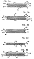
- Figs. 3A-3E are schematic, sectional illustrations showing five other types of CFRAAE, denoted Types 2 through 6, in accordance with preferred embodiments of the present invention. These types allow the displacement of a moving member to be converted into a proportional capacitance change without the constraint of electrical connection to the rotor. They can be used conveniently for angular encoders with unlimited rotation, and some of them can be employed for linear displacement sensing, as well.
- Fig. 3A illustrates a Type 2 encoder 70.
- a patterned, electrically non-conductive (dielectric) rotor 76 is situated between two stationary stator elements 72 and 74, each comprising a non-conductive substrate 73.
- Element 72 is coated with conductive transmitter plates 78 and 80, and element 74 is coated with a conductive receiver plate 82.
- Transmitter plates 78 and 80 are electrically excited and interact capacitively with receiver plate 82.
- the presence of rotor 76 increases the capacitance between the plates in accordance with its dielectric constant.
- This type of encoder is relatively insensitive to rotor tilt and axial position. An encoder of this type is described in the above-mentioned U.S. Patent 5,099,386 .
- Fig. 3C illustrates a Type 4 encoder 94, which is similar to Type 3 except that both sides of rotor 76 are coated with conductive coatings 96 and 98, respectively, which are electrically interconnected but otherwise floating. If the coatings are patterned, then the rotor serves as an angle-dependent coupling bridge between transmitter plates 78 and 80 and receiver plate 82.
- Type 4 encoders known in the art are described in the above-mentioned U.S. Patents 3,845,377 , 3,312,892 , 4,092,579 , 4,851,835 , 4,238,781 and 4,788,546 .
- Fig. 3D illustrates a Type 5 encoder 100, which can be considered a "foldback" version of Type 4.
- transmitter plates 78 and 80 and receiver plate 82 are placed on a common stationary substrate 73 of a single stator 102 on one side of rotor 76.
- a conductive pattern 104 on the rotor is energized by the transmitter plates and couples back to the receiver plate.
- the output signal from the receiver plate is proportional to the variable mutual capacitance between the rotor and the stator.
- Type 5 encoders known in the art are described in the above-mentioned U. S. Patents 3,961,318 and 4,429,307 .
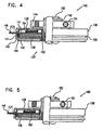
- Stator 141 preferably comprises a multi-layer printed-circuit board, on which processing circuitry 138 is mounted. A portion 146 of the board of stator 141 extends outside housing 139 to serve as a connection terminal. Stator 142 has an electrically-conductive area thereon which serves as an electrostatic field transmitter, and stator 141 has a corresponding area that serves as the receiver.
- the stators are electrically interconnected by means of an elastomeric directional conductor 147, known commercially as "Zebra", which forms the connection between the stators under pressure applied when housing 139 is closed, and does not need soldering.
- Rotor 148 which preferably is of the form that is illustrated schematically in Fig. 19 , has an axial extension 149 with a center hole for direct mounting to a host shaft 150 by means of a clamp ring 151.
- This hollow-shaft attachment scheme has the advantages of simplicity and compactness.
- a peripheral grove 155 receives mounting screws (not shown) which hold housing 139 in a manner known in the art as a servo-mount.
- An inner conductive sleeve 152 (along with an optional outer sleeve 153, shown in Fig. 6 ) serves to create a labyrinth 137.
- encoder 140 is enabled by high mechanical mounting error-tolerance afforded by the present invention, as described further hereinbelow, which is especially significant if encoder 140 is a multi-pole CFRAAE
- hollow-shaft concept to optical encoders necessitates not only internal bearings, to preserve the radial alignment between the rotor and stator, but also mounting the complete encoder housing on a flexible mounting frame to absorb mechanical misalignment between the hollow shaft of the encoder and the host shaft on which it is mounted.
- a typical optical encoder of this type is the model HS35 Sealed Hollowshaft, produced by Danaher Controls, of Gurnee, Illinois.
- Fig. 6 is a schematic, sectional illustration of encoder 140 showing details of an electrostatic protection scheme, in accordance with a preferred embodiment of the present invention.
- Stators 141 and 142 are shown to comprise printed circuit substrates 168 and 169, respectively having a receiving plate 170 and transmitting plates 172 plated thereon.
- Rotor 148 has an electrically active pattern, i.e., one that alters the capacitance between the transmitting and receiving plates.
- the rotor comprises a printed circuit substrate with conductive portions plated thereon to form the pattern.
- the stators, the rotor and air gaps therebetween, as well as at least a portion of processing circuitry 138, mainly the receiver preamplifier, are protected by an electrostatic shield 173.
- Both encoder housing 139 (shown in Fig. 4 ) and shaft 150 are electrically neutral and may assume any potential. Unlike encoders known in the art, the housing does not serve any electrical function and can be made economically out of plastic.
- a shield 166 over circuitry 138 preferably comprises a conductive coating on the inside of the housing, which is commonly grounded with shield 173. The ground connection to shield 166 can be obtained by contact with the printed circuit board ground of stator 141 or through a flexible leaf (not shown). Alternatively, shield 166 can be made of sheet metal.
- Pattern 195 is held at the fixed potential by means of an amplifier 182, which is coupled between an auxiliary annular plate 198 on stator 196 and an auxiliary transmitter plate 190 on stator 191. To the extent that pattern 195 is electrically floating, it acquires an AC potential from transmitter plates 192 in accordance with its instantaneous position. This AC potential interacts with plate 198 to generate a voltage, which is amplified and inverted by amplifier 182. The resulting voltage V O2 is applied to plate 190 in order to reduce the voltage on plate 198 via capacitive coupling through conductive pattern 195.
- the geometry of encoder 188 is such that plate 198 faces only rotor pattern 195, and is hidden from transmitter plates 192 and 190.
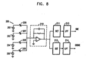
- Each channel includes a synchronous detector 211 or 212 and a low-pass filter 213 or 214.
- Synchronous detector 211 is fed by an in-phase reference signal from source 202, and its output is filtered by low-pass filter 213 to provide the sine signal.
- Synchronous detector 212 is fed by a quadrature reference signal from source 203, and its output is filtered by low-pass filter 214 to provide the cosine signal.
- the sine and cosine signals are preferably digitized and processed by a microcomputer or a digital signal processor (not shown in the figures), as is known in the art.
- the processing typically comprises a division operation for obtaining the tangent of the rotation angle, and the angle itself is then derived by algebraic calculation or by means of a look-up table.
- the signal/noise ratio at the sine and cosine outputs in capacitive encoders known in the art, as described hereinabove, is proportional to the square root of t/T, wherein T is the period of the reference square wave, and t is the aperture time of the sampling, which invariably is much shorter than T.
- Synchronous detection provides a far superior signal/noise ratio to time sampling, since its output is essentially the average value of many samples over the period T.
- Fig. 9 is a schematic circuit diagram illustrating an implementation of circuit 200, in accordance with a preferred embodiment of the present invention.
- U 1 may comprise any suitable type of discrete or integrated FET-input operational amplifier.
- U 2 is a general purpose operational amplifier.
- U 3 is a low charge-injection analog switch, such as a MAX 393, made by Maxim Integrated Products of Sunnyvale, California.
- U 3 selects either the output of U 1 or U 2 , as commanded by the square wave pulses Syncl or Sync2 from sources 202 and 203, respectively.
- the gains of the sine and cosine processing channels are thus very nearly the same, since they share U 1 and U 2 and are very insensitive to switch resistance in U 3 .
- the two channels share the same electronic components except for low-pass filters 213 and 214, which, however, have a gain of unity.
- the actual signal gains can vary, mainly due to variations in capacitor C 1 associated with amplifier 210. But since the measured angle is calculated based on the ratio of the two outputs, the gain variation is the same in both channels, and no accurate or stable components are needed.
- the performance of this signal processing method is very good. For example, a 12 bit analog/digital conversion of the output signals of a 32 pole-pair version was found to provide an angular resolution of 19 bits over a bandwidth of 10kHz.
- the encoder itself comprises a transmitting stator 240, a receiving stator 248 and rotor 174.
- Transmitting stator 240 comprises a transmitter plate 241, along with virtual ground auxiliary plate 170.
- Receiving stator 248 has four receiver quadrant plates 247, labeled A, B, C, and D, along with virtual ground auxiliary plate 178, coupled via virtual grounding loop amplifier 182 to plate 170.
- the four receiver quadrant plates are connected respectively to four charge amplifiers 250, 251, 252, and 253, which generate corresponding AC output voltages Va, Vb, Vc, and Vd.
- the amplitudes of the voltages Va-Vc and Vb-Vd are proportional to the sine and cosine of the rotation angle, as in an inductive resolver.
- the band-pass filters can be simple Wien-bridge networks. Also, since encoder 230 has four separate signal channels, unlike in the PQE scheme described hereinabove, and gain matching of the channels is not guaranteed, gain equalization is needed in production, typically by resistor trimming.
- Type 5 multi-speed CFRAAEs employing a single stator and a single rotor for both channels, have not been proposed in the prior art, perhaps because mutual interference between the two channels has in the past rendered them impractical. This configuration is explicitly dismissed in the above-mentioned article by Arnold and Heddergott.
- Figs. 12A and 12B are, respectively, top views of conductive plates on a stator 300 and a rotor 310 of a Type 5 (single stator) two-speed encoder, in accordance with a preferred embodiment of the present invention.
- Stator 300 comprises fine transmitter plates 313, coarse transmitter plates 314 and a receiver plate 312.
- Rotor 310 comprises fine pattern plate 317 coarse pattern plate 315, and a coupling plate 316 opposite receiver plate 312. All of the rotor plates are interconnected. The separation between plates 315 and 316 is unnecessary and is shown only for purposes of illustration. It is noted that both the coarse and fine patterns on rotor 310 are smoothly varying, without sharp boundary points, unlike multi-speed rotors known in the art. Consequently, when the signals from stator 300 are processed by circuitry as described hereinbelow, the encoder will give smooth, clean sinusoidal outputs, substantially without distortions that could reduce the accuracy of angle measurement.
- Fig. 13 is a schematic diagram of a signal conditioning circuit 330 for use with a two-speed encoder, in accordance with a preferred embodiment of the present invention.
- Circuit 330 uses a PQE approach, substantially similar to that described hereinabove with reference to circuit 200, but with separate coarse processing channels 328 and fine processing channels 329.
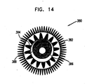
- Fig. 14 is a top view of conductive plates on a rotor 380 of a three-speed, Type 5 CFRAAE, in accordance with another preferred embodiment of the present invention.
- the rotor includes a fine channel 382, a medium channel 384, and a coarse channel 386, along with a coupling plate 388. It is to be used in conjunction with a suitably-adapted stator and signal conditioning circuitry, with three processing channels instead of two.
- the configuration of Fig. 14 is useful, for example, in large-diameter encoders with many cycles in the fine channel. In such cases, the coarse channel may not be accurate enough to correctly identify the proper fine cycle.
- the addition of medium channel 384, with a number of cycles intermediate between those of the coarse and fine channels, can solve the problem by first identifying the proper cycle in the medium channel and then in the fine channel.
- Fig. 15 is a schematic circuit diagram showing a two-state switchable signal conditioning circuit 420 for use with a two-speed rotary encoder, such as that illustrated by Figs. 12A-B , in accordance with a preferred embodiment of the present invention.
- Circuit 420 has the advantages of greater simplicity and reduced component count relative to multi-channel circuits such as that shown in Fig. 13 .
- Variable capacitances 429 to 432 represent the fine-channel mutual capacitances of the encoder
- variable capacitances 433 to 436 represent the coarse-channel mutual capacitances.
- Switches 425 to 428 are commanded by a common logic signal (not shown) to apply excitation voltages 421 to 424, or ground potential, to either the fine-channel or coarse-channel capacitances, so that alternately fine and coarse angle readings are made.
- a charge amplifier 447 provides an output voltage that is processed by a synchronous detectors 448 and 449 and low-pass filters 450 and 451 to provide the sine and cosine outputs for whichever of the channels (fine or coarse) has been switched on.
- Figs. 16A and 16B are top views of conductive plates on a stator 460 and a rotor 470, respectively, making up a two-speed Type 5 CFRAAE, in accordance with a preferred embodiment of the present invention.
- a multi-pole variable capacitance between the rotor and the stator is used to generate both coarse and fine angle measurements.
- the resulting practical advantage is that for a given outside diameter of the encoder, a larger center hole can be made, which accommodates a relatively larger range of shaft diameters.
- Stator 460 comprises fine transmission plates 467 and quadrant receiver plates 463 to 466.
- the fine plates interact with a fine pattern plate 468 on rotor 470.
- An eccentric coupling plate 461 on the rotor couples the interaction to the receiver plates. Because of the eccentricity of plate 461, the coupling capacitance is not rotationally independent unless all four quadrant capacitances are summed. When they are summed, an accurate fine channel reading is obtained.
- Fig. 17 is a schematic block diagram illustrating a signal processing circuit 480 for use with the encoder of Figs. 16A and 16B , in accordance with a preferred embodiment of the present invention.
- a signal processing circuit 480 for use with the encoder of Figs. 16A and 16B , in accordance with a preferred embodiment of the present invention.
- four pairs of DC voltages A 1 , A 2 , A 3 and A 4 and B 1 , B 2, B 3 and B 4 are obtained from the outputs of the respective sine and cosine channels of circuit 480. This is done by sequentially closing switches 490, 491, 492 and 493, and sampling the output DC voltages that appear at the outputs of filters 509 and 510.
- Each DC voltage is the result of fine capacitances 482, 483, 484 and 485 and of a specific quadrant coupling capacitance 486, 487, 488 or 489 (corresponding respectively to quadrants 463, 464, 465 and 466 in Fig. 16A ), together with the fixed gain of charge amplifier 506, synchronous demodulators 507 and 508 and low-pass filters 509 and 510.
- the corresponding vector sum of each pair of voltages is then calculated to provide magnitudes R 1 , R 2 , R 3 , and R 4 , which are proportional to the values of the quadrant coupling capacitances at the particular shaft angle.
- the diagonal pair differences of R 1 - R 3 and R 2 - R 4 are proportional to the desired sine and cosine of the coarse shaft angle.
- the four switches 490 to 493 are closed, whereby the encoder is switched to the fine mode.
- voltage sources 494 to 497 and variable capacitances 482 to 485, due to interaction of the fine stator plates with the fine rotor pattern, are used to determine the fine shaft angle.
- Figs. 18A, 18B and 18C are top views of a transmitting stator 520, a rotor 525 and a receiving stator 527, respectively, which together make up a Type 4 encoder, in accordance with a preferred embodiment of the present invention.
- This encoder exemplifies a second scheme for obtaining single-pole signals from a multi-pole mutual capacitance.
- Stator 520 includes a multi-pole transmitter array, comprising multiple transmitter plates 529, as in rotor 270 shown in Fig. 11B . In this case, however, plates 529 are divided into four quadrant groups 521 to 524, each of which can be energized separately.
- Stator 527 includes an annular receiver plate 528.
- Rotor 525 has a multi-pole conductive pattern 526 on both sides, and the two conductive patterns are electrically connected.
- the output signals will include a once-per-rotation amplitude modulation if not all of the quadrants are energized.
- Such eccentricity or other deviation can easily be introduced.
- the sine and cosine of the coarse shaft angle are obtained.
- the sine and cosine of the fine channel are accurately obtained.
- a multi-pole rotor with a once-per-cycle symmetry defect is coupled to a stator having a similar sort of symmetry defect.
- stator 270 shown in Fig. 11B
- stator 270 may be decentered, or one segment 272 of the stator may be removed.
- Mutual interaction of the rotor and stator defects lead to a cyclic modulation of the signal magnitude R.
- R is monitored in order to identify the position where it reaches its maximum or minimum value. This position is defined as the index position of the rotor.
- the cyclic error in the fine signal which is associated with the above-mentioned cyclic modulation, is preferably corrected in order to provide an accurate, absolute reading.
- Such embodiments have the advantage that the center hole of the rotor can be made still larger, since only the fine pattern is required, without a coupling or coarse pattern plate.
- the coarse channel pattern is partly recessed by making the substrate thinner, so as to reduce moisture effects by making the capacitance per unit area in the recessed pattern smaller than in wet, non-recessed areas.
- Still another option is to make the conductive region of the rotor from a carbon-filled or other conductive polymer, which is co-injected with a non-conductive polymer for the other parts of the rotor.
- Fig. 20 is a schematic, sectional view of a Type 4 CFRAAE 538, as is known in the art, illustrating the effect of rotor tilt.
- Encoder 538 includes a first stator 540 with transmitter conductive pattern coatings 541 and 545; a second stator 542 with a receiver conductive coating 543; and a rotor 544, which is slightly tilted, with electrically interconnected conductive coatings 547 and 548.
- the narrower air gap on the right side of the encoder between stator 540 and rotor 544 increases the contribution of transmitter pattern 541 relative to pattern 545 to the overall signal received by stator 542.
- the difference in contributions affects the gain ratio between the two channels, resulting in an output error.
- the capacitance between rotor 544 and receiver coating 543 is also modified by the tilt, this effect is common to both contributions and does not influence their gain ratio.
- Fig. 21 is a schematic, sectional view of a Type 4 CFRAAE 560, in accordance with a preferred embodiment of the present invention.
- the conductive patterns on the two sides of a rotor 561 are segmented into multiple elements 562-570, which are mutually electrically insulated.
- the two faces of each element, with respective coatings 547 and 548, are electrically interconnected.
- the series connection of capacitances C 1 and C 2 between coating 545 and rotor element 562 and between the rotor element and coating 543, respectively, is substantially independent of the position of the rotor element 562.
- Fig. 23 is a schematic top view of a hybrid rotor 580, which combines two CFRAAE types in a single device, in accordance with a preferred embodiment of the present invention.
- Rotor 580 comprises a dielectric substrate which is molded to give a three-dimensional, multi-pole fine channel pattern 582. This pattern is, therefore, of Type 2.
- a conductive pattern 584 preferably segmented, as described hereinabove, is formed on the rotor substrate to serve as the coarse channel. The coarse pattern thus functions as a Type 4 CFRAAE.
- Other combinations of different types are also possible.
- CLDE capacitive linear displacement encoders
- Such encoders include a fixed element - a ruler - which spans the entire range of motion, and a moving element, typically made as short as practical and referred to as a reading head.
- the ruler can be shielded, for example, by a conductive bellows or by other means, as described hereinbelow, it is usually more convenient to shield the much shorter head. It is therefore preferable, although not essential, that the head portion of the CLDE include the receiver.
- the CLDE lacks circular symmetry and is not inherently insensitive to relative tilt between the ruler and head. Preferred embodiments of the present invention are designed to overcome this shortcoming.
- Fig. 31B is a schematic, sectional illustration of another Type 5 CLDE 680, similar in principle to CLDE 660, in accordance with a preferred embodiment of the present invention.
- CLDE 680 the ground protection is provided by an extension 684 of a moving head 682. It is therefore not necessary that ruler 662 include a ground connection.
Landscapes
- Physics & Mathematics (AREA)
- General Physics & Mathematics (AREA)
- Engineering & Computer Science (AREA)
- Power Engineering (AREA)
- Transmission And Conversion Of Sensor Element Output (AREA)
- Amplifiers (AREA)
- Semiconductor Integrated Circuits (AREA)
- Measuring Fluid Pressure (AREA)
- Measurement Of Length, Angles, Or The Like Using Electric Or Magnetic Means (AREA)
Claims (4)
- Kapazitiver Winkelcodierer zur Erfassung einer Rotation einer Welle, wobei der Codierer umfasst:zumindest einen Stator (270, 300), der einen Sender (272, 313, 314) für elektrostatisches Feld umfasst und derart angepasst ist, um ein elektrostatisches Feld zu erzeugen;einen Empfänger (312) für elektrostatisches Feld, der derart angepasst ist, um das elektrostatische Feld zu empfangen und ein Signal in Ansprechen darauf zu erzeugen;einen Rotor (260, 310), der derart angepasst ist, um mit der Welle zu rotieren, und der ein grobes (315) und ein feines (317) periodisches elektrisch aktives Muster darauf aufweist, wobei die Muster (315, 317) das elektrostatische Feld in Ansprechen auf eine Rotation der Welle durch Bewirken einer periodischen Änderung der Kapazität zwischen dem Sender und dem Empfänger modulieren; undeine Verarbeitungsschaltung (330), die mit dem Empfänger gekoppelt ist, um so die periodische Änderung in dem Signal zu erfassen und in Ansprechen auf die periodische Änderung grobe und feine Maße eines Rotationswinkels der Welle zu bestimmen,dadurch gekennzeichnet, dass das feine Muster (317) ein sich glatt änderndes sinusförmiges Muster ohne scharfe Randpunkte umfasst, das um den Umfang der Welle angeordnet ist.
- Codierer nach Anspruch 1, wobei der Rotor (380) ein periodisches elektrisch aktives Zwischenmuster (384) umfasst, wobei das Zwischenmuster (384) einen dritten Verarbeitungskanal bereitstellt.
- Codierer nach einem der Ansprüche 1 oder 2, wobei der zumindest eine Stator (270, 300) eine Statorplatte umfasst, die an einer ersten Seite des Rotors (260, 310) positioniert ist und darauf ausgebildet sowohl den Sender (313, 314) für elektrostatisches Feld als auch den Empfänger (312) für elektrostatisches Feld aufweist.
- Codierer nach einem der Ansprüche 1 bis 3, wobei der Feldsender (272, 313, 314) derart angepasst ist, um das elektrostatische Feld periodisch mit zumindest einer Frequenz zu erzeugen, und wobei die Verarbeitungsschaltung (330) zumindest einen Synchrondetektor (349 - 352) umfasst, der derart angepasst ist, um das Signal synchronisiert mit dem erzeugten Feld zu verarbeiten.
Applications Claiming Priority (3)
| Application Number | Priority Date | Filing Date | Title |
|---|---|---|---|
| US294749 | 1999-04-19 | ||
| US09/294,749 US6492911B1 (en) | 1999-04-19 | 1999-04-19 | Capacitive displacement encoder |
| EP00914345A EP1173730B1 (de) | 1999-04-19 | 2000-03-30 | Kapazitiver weggeber |
Related Parent Applications (2)
| Application Number | Title | Priority Date | Filing Date |
|---|---|---|---|
| EP00914345A Division EP1173730B1 (de) | 1999-04-19 | 2000-03-30 | Kapazitiver weggeber |
| EP00914345.4 Division | 2000-03-30 |
Publications (2)
| Publication Number | Publication Date |
|---|---|
| EP1538422A1 EP1538422A1 (de) | 2005-06-08 |
| EP1538422B1 true EP1538422B1 (de) | 2010-05-12 |
Family
ID=23134776
Family Applications (2)
| Application Number | Title | Priority Date | Filing Date |
|---|---|---|---|
| EP04028370A Expired - Lifetime EP1538422B1 (de) | 1999-04-19 | 2000-03-30 | Kapazitiver Lagesensor |
| EP00914345A Expired - Lifetime EP1173730B1 (de) | 1999-04-19 | 2000-03-30 | Kapazitiver weggeber |
Family Applications After (1)
| Application Number | Title | Priority Date | Filing Date |
|---|---|---|---|
| EP00914345A Expired - Lifetime EP1173730B1 (de) | 1999-04-19 | 2000-03-30 | Kapazitiver weggeber |
Country Status (11)
| Country | Link |
|---|---|
| US (3) | US6492911B1 (de) |
| EP (2) | EP1538422B1 (de) |
| JP (2) | JP2002542476A (de) |
| KR (1) | KR20020010607A (de) |
| CN (2) | CN1847797B (de) |
| AT (2) | ATE467822T1 (de) |
| AU (1) | AU3573800A (de) |
| CA (1) | CA2368140A1 (de) |
| DE (2) | DE60044403D1 (de) |
| TW (1) | TW573116B (de) |
| WO (1) | WO2000063653A2 (de) |
Cited By (2)
| Publication number | Priority date | Publication date | Assignee | Title |
|---|---|---|---|---|
| EP2615424A1 (de) | 2012-01-13 | 2013-07-17 | SICK STEGMANN GmbH | Verfahren zur Überwachung der korrekten Funktion eines periodisch modulierten Sensors zur Steuerung der Position eines rotierenden Systems und Steuerungsvorrichtung zur Durchführung des Verfahrens |
| EP2626670A1 (de) | 2012-02-09 | 2013-08-14 | SICK STEGMANN GmbH | Verfahren zum Erhalt von Informationen zur Phase eines Drehsystem |
Families Citing this family (193)
| Publication number | Priority date | Publication date | Assignee | Title |
|---|---|---|---|---|
| US7469381B2 (en) | 2007-01-07 | 2008-12-23 | Apple Inc. | List scrolling and document translation, scaling, and rotation on a touch-screen display |
| US6587093B1 (en) * | 1999-11-04 | 2003-07-01 | Synaptics Incorporated | Capacitive mouse |
| US6608483B1 (en) * | 2001-11-13 | 2003-08-19 | John P. Hill | Quadrature differential charge commutation sensor enabling wide bandwith field mills and other electrostatic field measuring devices |
| US8269485B2 (en) * | 2002-05-24 | 2012-09-18 | Asylum Research Corporation | Linear variable differential transformer with digital electronics |
| JP3481233B1 (ja) * | 2002-05-27 | 2003-12-22 | 沖電気工業株式会社 | キャパシタ構造の製造方法及びキャパシタ素子の製造方法 |
| US6651489B1 (en) * | 2002-06-12 | 2003-11-25 | Morgan Yang | Driving force detecting device for cycles |
| KR100498070B1 (ko) * | 2002-12-26 | 2005-07-01 | 학교법인 포항공과대학교 | 엔코더형 전기적 용량센서 |
| US6776028B1 (en) * | 2003-04-29 | 2004-08-17 | Ofi Testing Equipment, Inc. | Induction sensor viscometer |
| JP2005030901A (ja) * | 2003-07-11 | 2005-02-03 | Alps Electric Co Ltd | 容量センサ |
| KR100538225B1 (ko) * | 2003-07-16 | 2005-12-21 | 삼성전자주식회사 | 엔코더의 신호처리방법 및 장치 |
| US6892590B1 (en) * | 2003-11-04 | 2005-05-17 | Andermotion Technologies Llc | Single-balanced shield electrode configuration for use in capacitive displacement sensing systems and methods |
| US7429976B2 (en) * | 2003-11-24 | 2008-09-30 | Avago Technologies Ecbu Ip (Singapore) Pte. Ltd. | Compact pointing device |
| US7570247B2 (en) * | 2003-11-24 | 2009-08-04 | Avago Technologies Ecbu Ip (Singapore) Pte. Ltd. | Modular assembly for a self-indexing computer pointing device |
| KR100602800B1 (ko) * | 2003-12-10 | 2006-07-20 | 안진우 | 아날로그 엔코더장치에 의한 에스알엠의 정밀 각도 제어방법 |
| JP2005241376A (ja) * | 2004-02-25 | 2005-09-08 | Denso Corp | 回転角度センサ |
| US7268451B2 (en) * | 2004-03-22 | 2007-09-11 | General Motors Corporation | Motor resolver assembly and method of measuring speed and position of a motor rotor |
| CN101218512A (zh) * | 2004-06-23 | 2008-07-09 | Fe技术服务公司 | 电容传感技术 |
| US7075317B2 (en) * | 2004-08-06 | 2006-07-11 | Waters Investment Limited | System and method for measurement of small-angle or small-displacement |
| US7135874B2 (en) * | 2004-08-06 | 2006-11-14 | Waters Investments Limited | System and method for enhanced measurement of rheological properties |
| US7259695B2 (en) * | 2004-09-17 | 2007-08-21 | Andermotion Technologies Llc | Low-profile multi-turn encoder systems and methods |
| WO2007011402A2 (en) * | 2004-10-26 | 2007-01-25 | Georgia Tech Research Corporation | Displacement sensor |
| US7426859B2 (en) * | 2004-10-29 | 2008-09-23 | Archangel Systems, Inc. | Motion sensor and method for detecting motion |
| CN2765139Y (zh) * | 2004-12-27 | 2006-03-15 | 杨忠义 | 双柱式数显高度规 |
| US7978173B2 (en) * | 2005-01-14 | 2011-07-12 | Avago Technologies Ecbu Ip (Singapore) Pte. Ltd. | Pointing device including a moveable puck with mechanical detents |
| US20060176189A1 (en) * | 2005-02-06 | 2006-08-10 | David Bar-On | Two Dimensional Layout, High Noise Immunity, Interleaved Channels Electrostatic Encoder |
| US7078915B1 (en) * | 2005-02-22 | 2006-07-18 | Delphi Technologies, Inc | Angular position sensor for rotating components such as steering columns |
| US7586480B2 (en) | 2005-02-28 | 2009-09-08 | Avago Technologies Ecbu Ip (Singapore) Pte. Ltd. | Hybrid pointing device |
| CN100489888C (zh) * | 2005-08-12 | 2009-05-20 | 鸿富锦精密工业(深圳)有限公司 | 触摸式感应装置 |
| US7417202B2 (en) * | 2005-09-02 | 2008-08-26 | White Electronic Designs Corporation | Switches and systems employing the same to enhance switch reliability and control |
| US7439465B2 (en) * | 2005-09-02 | 2008-10-21 | White Electronics Designs Corporation | Switch arrays and systems employing the same to enhance system reliability |
| US7194377B1 (en) * | 2005-09-26 | 2007-03-20 | Hitachi Automotive Products (Usa), Inc. | Method for calibrating an analog sensor |
| CN101317080A (zh) * | 2005-09-29 | 2008-12-03 | Jpk器具股份有限公司 | 用于可移动部件在检验系统中定位的方法和装置 |
| KR100713776B1 (ko) * | 2005-10-04 | 2007-05-02 | 에스알텍 주식회사 | 검출 전류의 비교를 통한 에스알엠의 여자 위치 검출 방법및 장치 |
| SE529249C2 (sv) * | 2005-10-14 | 2007-06-12 | Hexagon Metrology Ab | Förfarande vid signalbehandling vid kapacitiva mätskalor |
| US7701440B2 (en) * | 2005-12-19 | 2010-04-20 | Avago Technologies Ecbu Ip (Singapore) Pte. Ltd. | Pointing device adapted for small handheld devices having two display modes |
| JP4869706B2 (ja) | 2005-12-22 | 2012-02-08 | 株式会社 日立ディスプレイズ | 表示装置 |
| DE102006007668A1 (de) * | 2006-02-18 | 2007-08-23 | Schaeffler Kg | Messeinrichtung zur Bestimmung eines Drehwinkels |
| US7763005B2 (en) | 2006-03-02 | 2010-07-27 | Covidien Ag | Method for using a pump set having secure loading features |
| US8021336B2 (en) * | 2007-01-05 | 2011-09-20 | Tyco Healthcare Group Lp | Pump set for administering fluid with secure loading features and manufacture of component therefor |
| US7927304B2 (en) | 2006-03-02 | 2011-04-19 | Tyco Healthcare Group Lp | Enteral feeding pump and feeding set therefor |
| US7722573B2 (en) | 2006-03-02 | 2010-05-25 | Covidien Ag | Pumping apparatus with secure loading features |
| US7722562B2 (en) | 2006-03-02 | 2010-05-25 | Tyco Healthcare Group Lp | Pump set with safety interlock |
| US7443174B2 (en) * | 2006-04-06 | 2008-10-28 | Freescale Semiconductor, Inc. | Electric field reciprocal displacement sensors |
| ITMI20060715A1 (it) * | 2006-04-11 | 2007-10-12 | Abb Service Srl | Dispositivo accessorio per un trasmettitore di campo |
| US20070247446A1 (en) * | 2006-04-25 | 2007-10-25 | Timothy James Orsley | Linear positioning input device |
| CN101534630A (zh) * | 2006-05-24 | 2009-09-16 | Tt电子技术有限公司 | 多圈旋转传感器 |
| DE102006026543B4 (de) * | 2006-06-07 | 2010-02-04 | Vogt Electronic Components Gmbh | Lagegeber und zugehöriges Verfahren zum Erfassen einer Position eines Läufers einer Maschine |
| CN100593767C (zh) * | 2006-06-30 | 2010-03-10 | 深圳市大族激光科技股份有限公司 | 电容传感器的控制方法 |
| US7889176B2 (en) * | 2006-07-18 | 2011-02-15 | Avago Technologies General Ip (Singapore) Pte. Ltd. | Capacitive sensing in displacement type pointing devices |
| JP4760611B2 (ja) * | 2006-08-28 | 2011-08-31 | 日産自動車株式会社 | 静電容量検出型回転センサ |
| US7550965B2 (en) | 2006-11-14 | 2009-06-23 | Raytheon Company | Angular position measurement device |
| DE102006056609A1 (de) * | 2006-11-30 | 2008-06-05 | Maxon Motor Ag | Kapazitiver Winkelkodierer und Feedereinschub für Bestückungsmaschinen von Leiterplatten |
| US7560686B2 (en) | 2006-12-11 | 2009-07-14 | Tyco Healthcare Group Lp | Pump set and pump with electromagnetic radiation operated interlock |
| US20080147008A1 (en) * | 2006-12-15 | 2008-06-19 | Tyco Healthcare Group Lp | Optical detection of medical pump rotor position |
| CN100460821C (zh) * | 2007-06-16 | 2009-02-11 | 昝昕武 | 一种发动机节气门位置传感方法及传感器 |
| KR20090007021A (ko) * | 2007-07-13 | 2009-01-16 | 삼성전자주식회사 | 엔코더 장치 및 이 장치의 캘리브레이션 방법 |
| US8232963B2 (en) * | 2007-08-27 | 2012-07-31 | Avago Technologies Ecbu Ip (Singapore) Pte. Ltd. | Control and data entry apparatus |
| US20090058802A1 (en) * | 2007-08-27 | 2009-03-05 | Avago Technologies Ecbu Ip (Singapore) Pte. Ltd. | Input device |
| DE112008002132A5 (de) * | 2007-08-29 | 2010-06-24 | Dr. Fritz Faulhaber Gmbh & Co. Kg | Kleinst-Elektromotor mit integriertem Encoder sowie kapazitiver Positionscodierer hierfür |
| US8102276B2 (en) * | 2007-08-31 | 2012-01-24 | Pathfinder Energy Sevices, Inc. | Non-contact capacitive datalink for a downhole assembly |
| US20090058430A1 (en) * | 2007-09-05 | 2009-03-05 | Sentrinsic | Systems and Methods for Sensing Positions of Components |
| US7570066B2 (en) * | 2007-11-01 | 2009-08-04 | Seagate Technology Llc | Simultaneous detection of in-plane and out-of-plane position displacement with capacitive sensors |
| US7978175B2 (en) * | 2007-11-23 | 2011-07-12 | Avago Technologies Ecbu Ip (Singapore) Pte. Ltd. | Magnetic re-centering mechanism for a capacitive input device |
| CN100547354C (zh) * | 2007-11-26 | 2009-10-07 | 桂林市晶瑞传感技术有限公司 | 用于绝对位置测量的绝对型圆容栅传感器测量装置 |
| US20090135157A1 (en) * | 2007-11-27 | 2009-05-28 | Avago Technologies Ecbu Ip (Singapore) Pte. Ltd. | Capacitive Sensing Input Device with Reduced Sensitivity to Humidity and Condensation |
| DE202007017856U1 (de) * | 2007-12-19 | 2009-04-23 | Mymotors & Actuators Gmbh | Kleinst-Elektromotor mit integrierter Motorspule |
| US8299781B2 (en) * | 2008-03-07 | 2012-10-30 | Minebea Co., Ltd. | Reactance sensors of radial position for magnetic bearings and bearingless drives |
| KR100971494B1 (ko) * | 2008-05-23 | 2010-07-21 | 포항공과대학교 산학협력단 | 기계적 가이드를 가지는 면적변화형 정전용량형 센서 |
| JP5160987B2 (ja) * | 2008-06-09 | 2013-03-13 | ハイデンハイン株式会社 | 回転規制部材を有するエンコーダ |
| US8704536B2 (en) * | 2008-08-04 | 2014-04-22 | The Regents Of The University Of California | Lateral displacement and rotational displacement sensor |
| JP5263822B2 (ja) * | 2008-08-20 | 2013-08-14 | 株式会社青電舎 | 回転式静電型エンコーダ |
| KR101005850B1 (ko) * | 2008-10-09 | 2011-01-05 | (주) 기홍 | 가연성 또는 유기성 폐기물의 건조 및 탄화 장치 |
| US8294539B2 (en) | 2008-12-18 | 2012-10-23 | Analog Devices, Inc. | Micro-electro-mechanical switch beam construction with minimized beam distortion and method for constructing |
| EP2199751B1 (de) * | 2008-12-19 | 2012-08-08 | MENTOR GmbH & Co. Präzisions-Bauteile KG | Kapazitiver Drehwinkelsensor |
| US7804427B1 (en) * | 2009-03-20 | 2010-09-28 | Honda Motor Co., Ltd. | Device and method for automatic reset of encoder |
| KR200445514Y1 (ko) * | 2009-03-23 | 2009-08-06 | 이재진 | 접촉식 검출센서 |
| DE102009019172A1 (de) * | 2009-04-28 | 2010-11-04 | Hengstler Gmbh | Kapazitiver Drehsensor |
| EP2437657B1 (de) * | 2009-06-05 | 2018-05-23 | Koninklijke Philips N.V. | Kapazitives messsystem |
| DE102009031664A1 (de) | 2009-07-04 | 2011-01-05 | Camille Bauer Ag, Wohlen | Kapazitiver Drehwinkelsensor |
| US8253641B1 (en) * | 2009-07-08 | 2012-08-28 | Northrop Grumman Systems Corporation | Wideband wide scan antenna matching structure using electrically floating plates |
| CN101995208B (zh) | 2009-08-13 | 2012-06-27 | 西门子(中国)有限公司 | 一种电容式线性位移测量的装置和方法 |
| US8587328B2 (en) | 2009-08-25 | 2013-11-19 | Analog Devices, Inc. | Automatic characterization of an actuator based on capacitance measurement |
| DE102009044542B3 (de) * | 2009-11-16 | 2011-05-19 | Ina - Drives & Mechatronics Gmbh & Co. Ohg | Wälzlager mit einer Sensoreinheit |
| EP2330388B1 (de) * | 2009-12-04 | 2013-09-04 | Hengstler GmbH | Verfahren zur Bestimmung des absoluten Winkels eines kapazitiven Bewegungscodierers |
| US9103769B2 (en) * | 2009-12-15 | 2015-08-11 | The Regents Of The University Of California | Apparatus and methods for controlling electron microscope stages |
| DE102010000671A1 (de) | 2010-01-05 | 2011-07-07 | Robert Bosch GmbH, 70469 | Drehwinkelsensor |
| TWI425187B (zh) * | 2010-01-14 | 2014-02-01 | Hiwin Mikrosystem Corp | 角度解析裝置 |
| JP2011163865A (ja) * | 2010-02-08 | 2011-08-25 | Seidensha Co Ltd | 回転型静電エンコーダ |
| US8154274B2 (en) | 2010-05-11 | 2012-04-10 | Tyco Healthcare Group Lp | Safety interlock |
| CN102042839B (zh) * | 2010-08-19 | 2012-07-25 | 葛幸华 | 两个不同周期测量传感器组合成绝对式角度编码器的原理 |
| DE102010046778B4 (de) * | 2010-09-28 | 2017-11-02 | Trw Automotive Electronics & Components Gmbh | Kapazitiver Drehgeber |
| DE102010050608A1 (de) | 2010-11-05 | 2012-05-10 | Hengstler Gmbh | Kapazitiver Drehsensor |
| US8772705B2 (en) | 2010-12-01 | 2014-07-08 | Avago Technologies General Ip (Singapore) Pte. Ltd. | Interpolation circuitry for optical encoders |
| US8757009B2 (en) | 2010-12-08 | 2014-06-24 | Danaher Uk Industries Limited | Fuel dispenser flow meter sensor fraud prevention |
| US9092082B2 (en) | 2010-12-22 | 2015-07-28 | Synaptics Incorporated | Methods and apparatus for mounting a touch sensor device |
| JP5840374B2 (ja) * | 2011-03-31 | 2016-01-06 | オリエンタルモーター株式会社 | アブソリュートエンコーダ装置及びモータ |
| US9641174B2 (en) * | 2011-04-11 | 2017-05-02 | The Regents Of The University Of California | Use of micro-structured plate for controlling capacitance of mechanical capacitor switches |
| CN103608852B (zh) | 2011-04-20 | 2016-12-07 | 吉尔巴科公司 | 燃料分配器流量计欺诈检测和预防 |
| TWI490456B (zh) | 2011-04-29 | 2015-07-01 | Elan Microelectronics Corp | Differential Capacitance Sensing Circuit and Method |
| CN102798405B (zh) * | 2011-05-27 | 2015-08-19 | 西门子公司 | 电容式旋转编码器和感应旋转角度的方法 |
| DE102011078077A1 (de) * | 2011-06-24 | 2012-12-27 | Ident Technology Ag | Leiterplatte mit Elektrodenkonfiguration eines kapazitiven Sensors |
| DE102011087493B4 (de) | 2011-11-30 | 2016-12-22 | Ifm Electronic Gmbh | Kapazitiver Drehgeber |
| DE102011087494B4 (de) | 2011-11-30 | 2021-01-28 | Ifm Electronic Gmbh | Kapazitiver Sensor zur Lage- oder Bewegungserkennung |
| US9513152B1 (en) * | 2011-12-20 | 2016-12-06 | Varec, Inc. | Liquid level transmitter utilizing low cost, capacitive, absolute encoders |
| EP2674764A1 (de) * | 2012-06-13 | 2013-12-18 | Aktiebolaget SKF | Verfahren zur Herstellung einer Sensoreinheit, Sensoreinheit und instrumentiertes Lager mit solch einer Sensoreinheit |
| DE102012218890A1 (de) * | 2012-10-17 | 2014-04-17 | Dr. Johannes Heidenhain Gmbh | Absolutes Positionsmessgerät |
| EP2746730B1 (de) * | 2012-12-21 | 2015-11-18 | SICK STEGMANN GmbH | Antriebssystem mit einem Winkelencoder |
| WO2014101031A1 (en) * | 2012-12-27 | 2014-07-03 | Siemens Aktiengesellschaft | Linear capacitive encoder and position determing method |
| US10691230B2 (en) | 2012-12-29 | 2020-06-23 | Apple Inc. | Crown input for a wearable electronic device |
| US10275117B2 (en) | 2012-12-29 | 2019-04-30 | Apple Inc. | User interface object manipulations in a user interface |
| DE102013102543B4 (de) | 2013-03-13 | 2024-02-01 | Minebea Mitsumi Inc. | Drehgeber mit geringer Leistungsaufnahme |
| CA2906141A1 (en) | 2013-03-15 | 2014-09-18 | Gilbarco Inc. | Fuel dispenser flow meter fraud detection and prevention |
| JP2014181929A (ja) * | 2013-03-18 | 2014-09-29 | Yamaha Corp | 静電型センサおよびスライド操作装置 |
| JP2014204361A (ja) * | 2013-04-08 | 2014-10-27 | 株式会社ビートソニック | 車載モニタリングシステムにおける車載カメラ用アダプター |
| EP2824426B1 (de) | 2013-07-09 | 2018-05-09 | Leica Geosystems AG | Kapazitiver Drehlagengeber |
| TWI497899B (zh) | 2013-08-05 | 2015-08-21 | Ind Tech Res Inst | 機構式編碼器 |
| US10545657B2 (en) | 2013-09-03 | 2020-01-28 | Apple Inc. | User interface for manipulating user interface objects |
| CN110795005A (zh) | 2013-09-03 | 2020-02-14 | 苹果公司 | 利用磁属性来操控用户界面对象的用户界面 |
| US10503388B2 (en) * | 2013-09-03 | 2019-12-10 | Apple Inc. | Crown input for a wearable electronic device |
| US12287962B2 (en) | 2013-09-03 | 2025-04-29 | Apple Inc. | User interface for manipulating user interface objects |
| US11068128B2 (en) | 2013-09-03 | 2021-07-20 | Apple Inc. | User interface object manipulations in a user interface |
| US10001817B2 (en) | 2013-09-03 | 2018-06-19 | Apple Inc. | User interface for manipulating user interface objects with magnetic properties |
| DE102013218294A1 (de) * | 2013-09-12 | 2015-03-12 | Zf Friedrichshafen Ag | Sinusoszillator und induktive Sensorik |
| CN103528605B (zh) * | 2013-10-15 | 2015-11-11 | 北京航空航天大学 | 一种电容型绝对式旋转编码器 |
| US9360511B2 (en) * | 2013-10-21 | 2016-06-07 | Qualcomm Mems Technologies, Inc. | Closed loop dynamic capacitance measurement |
| US10018654B2 (en) * | 2013-11-13 | 2018-07-10 | Semiconductor Components Industries, Llc | Sensor circuit for detecting rotation of an object and method therefor |
| US9714846B2 (en) * | 2013-12-31 | 2017-07-25 | Chicago Dial Indicator Company | Displacement measuring device with capacitive sensing |
| CN103822571B (zh) * | 2014-03-19 | 2016-11-02 | 重庆理工大学 | 基于单排多层结构的电场式时栅直线位移传感器 |
| CN103968750B (zh) * | 2014-05-09 | 2017-01-18 | 重庆理工大学 | 一种电场式时栅角位移传感器 |
| KR102247501B1 (ko) | 2014-05-09 | 2021-05-03 | 삼성전자주식회사 | 압전 구동 장치 및 이를 이용한 움직임 측정 방법 |
| CN110825299B (zh) | 2014-06-27 | 2024-03-29 | 苹果公司 | 尺寸减小的用户界面 |
| TWI676127B (zh) | 2014-09-02 | 2019-11-01 | 美商蘋果公司 | 關於電子郵件使用者介面之方法、系統、電子器件及電腦可讀儲存媒體 |
| US9684394B2 (en) | 2014-09-02 | 2017-06-20 | Apple Inc. | Button functionality |
| US10073590B2 (en) | 2014-09-02 | 2018-09-11 | Apple Inc. | Reduced size user interface |
| CN106797493A (zh) | 2014-09-02 | 2017-05-31 | 苹果公司 | 音乐用户界面 |
| US9983026B2 (en) * | 2014-09-25 | 2018-05-29 | Texas Instruments Incorporated | Multi-level rotational resolvers using inductive sensors |
| EP3040688B1 (de) | 2014-12-04 | 2018-04-18 | Hexagon Technology Center GmbH | Kapazitiver Linearencoder |
| EP3282230B1 (de) * | 2014-12-04 | 2020-02-05 | Hexagon Technology Center GmbH | Absoluter kapazitiver winkelencoder |
| JP6285572B2 (ja) * | 2014-12-15 | 2018-02-28 | 日立オートモティブシステムズ株式会社 | 電力変換装置 |
| JP6156747B2 (ja) | 2014-12-17 | 2017-07-05 | オリエンタルモーター株式会社 | 静電エンコーダ |
| EP3037898B1 (de) * | 2014-12-23 | 2017-06-21 | ETA SA Manufacture Horlogère Suisse | Elektromechanisches gerät, das einen kapazitiven detektor der winkelposition eines mobilen elementes umfasst, und verfahren zur detektion der winkelposition eines mobilen elementes |
| US10365807B2 (en) | 2015-03-02 | 2019-07-30 | Apple Inc. | Control of system zoom magnification using a rotatable input mechanism |
| US9829347B2 (en) * | 2015-06-03 | 2017-11-28 | Hiwin Mikrosystem Corp. | Capacitance sensation unit of plane position measurement device |
| JP6363559B2 (ja) | 2015-06-10 | 2018-07-25 | ファナック株式会社 | 異物の侵入を検出可能な回転角度検出器 |
| CN105486222B (zh) * | 2015-12-29 | 2019-04-19 | 崔星 | 一种电容式角位移传感器 |
| WO2017123959A1 (en) * | 2016-01-15 | 2017-07-20 | Joy Mm Delaware, Inc. | Support structure for rotary sensor |
| EP3430713B1 (de) | 2016-03-13 | 2022-01-26 | Servosense (SMC) Ltd. | Positionscodierer |
| CN106052546B (zh) * | 2016-05-20 | 2018-06-22 | 清华大学 | 一种分瓣电容式角位移传感器 |
| CN105953721B (zh) * | 2016-05-20 | 2018-06-22 | 清华大学 | 一种偏心电容式角位移传感器结构及其使用方法 |
| DE102016110085A1 (de) * | 2016-06-01 | 2017-12-07 | Miele & Cie. Kg | Vorrichtung und Verfahren zum Erfassen einer Drehposition eines drehbaren Elements, Steuergerät, Sensorsystem zum Ermitteln einer Drehposition eines drehbaren Elements und Haushaltgerät |
| DE102016210550B4 (de) * | 2016-06-14 | 2020-08-13 | Robert Bosch Gmbh | Sensorvorrichtung und Verfahren zur Herstellung einer Sensorvorrichtung |
| US9897466B2 (en) | 2016-07-18 | 2018-02-20 | Delphi Technologies, Inc. | Rotor position sensor signal correction |
| US10254134B2 (en) | 2016-08-04 | 2019-04-09 | Apple Inc. | Interference-insensitive capacitive displacement sensing |
| CN106289043B (zh) * | 2016-08-10 | 2019-04-12 | 成都芯通软件有限公司 | 一种电容式距离测量方法、装置及其定标方法 |
| CN106382947B (zh) * | 2016-11-29 | 2019-07-16 | 西安融智航空科技有限公司 | 一种高精度便携式二维位移编码器 |
| CN106643470B (zh) * | 2016-12-26 | 2019-04-23 | 清华大学 | 一种绝对式电容角位移测量传感器 |
| US10716219B2 (en) * | 2017-01-26 | 2020-07-14 | Lite-On Electronics (Guangzhou) Limited | Electronic product and manufacturing method thereof |
| CN106706008B (zh) * | 2017-03-09 | 2023-08-04 | 广东盈动高科自动化有限公司 | 差分电容编码器 |
| EP3438765B1 (de) * | 2017-08-04 | 2020-02-05 | ETA SA Manufacture Horlogère Suisse | Uhrwerk, das eine vorrichtung zur erfassung der winkelposition eines rads umfasst |
| FI3438764T3 (fi) * | 2017-08-04 | 2026-02-09 | Eta Sa Mft Horlogere Suisse | Kellon liike, joka käsittää laitteen pyörän kulma-asennon havaitsemiseksi |
| US10712360B2 (en) | 2017-09-27 | 2020-07-14 | Azoteq (Pty) Ltd | Differential charge transfer based accelerometer |
| CN108151675A (zh) * | 2017-11-16 | 2018-06-12 | 柳州健鱼科技有限公司 | 一种基于图像相位相关算法的电机转子位置检测 |
| DE102017128869B3 (de) * | 2017-12-05 | 2019-05-29 | Infineon Technologies Ag | Magnetwinkelsensoranordnung und Verfahren zum Schätzen eines Rotationswinkels |
| US10911061B2 (en) * | 2018-03-23 | 2021-02-02 | The Boeing Company | System and method for demodulation of resolver outputs |
| US10913550B2 (en) | 2018-03-23 | 2021-02-09 | The Boeing Company | System and method for position and speed feedback control |
| US10830591B2 (en) | 2018-03-23 | 2020-11-10 | The Boeing Company | System and method for dual speed resolver |
| US11185636B2 (en) * | 2018-07-26 | 2021-11-30 | Verily Life Sciences Llc | Electrostatic rotary encoder |
| US11229749B2 (en) | 2018-09-06 | 2022-01-25 | Verily Life Sciences Llc | Plate capacitor for dosage sensing |
| US11435830B2 (en) | 2018-09-11 | 2022-09-06 | Apple Inc. | Content-based tactile outputs |
| US10712824B2 (en) | 2018-09-11 | 2020-07-14 | Apple Inc. | Content-based tactile outputs |
| CN109631958B (zh) * | 2018-11-28 | 2021-03-02 | 赛卓电子科技(上海)有限公司 | 位置编码器 |
| CN109724632A (zh) * | 2019-01-24 | 2019-05-07 | 长春通视光电技术有限公司 | 二维曲面电容式编码器 |
| CN109682401A (zh) * | 2019-01-28 | 2019-04-26 | 上海奥感电子科技有限公司 | 一种电容式绝对值编码器 |
| CN110110711B (zh) * | 2019-06-06 | 2021-06-04 | 郑州轻工业学院 | 一种噪声信道下的迭代学习控制系统输入信号估计方法 |
| US11990801B2 (en) * | 2019-08-07 | 2024-05-21 | Wisconsin Alumni Research Foundation | Single substrate resolver/rectifier for brushless wound field synchronous machines |
| RU2724150C1 (ru) * | 2019-09-05 | 2020-06-22 | Открытое акционерное общество "Специальное Конструкторское Бюро Измерительных Систем" | Емкостной абсолютный преобразователь угловых перемещений |
| JP2021076530A (ja) | 2019-11-12 | 2021-05-20 | 愛三工業株式会社 | バルブ装置及びバルブ装置を搭載するシステム |
| KR102144254B1 (ko) * | 2020-04-03 | 2020-08-12 | 박천수 | 제로포스변환 벡터합성 능동형 리졸버 장치 |
| CN111562812B (zh) * | 2020-04-29 | 2022-03-11 | 维沃移动通信有限公司 | 电子设备 |
| RU200279U1 (ru) * | 2020-05-27 | 2020-10-15 | Акционерное общество "Научно-производственный центр "Полюс" | Емкостный дифференциальный датчик угла поворота вала |
| DE102020122368B4 (de) * | 2020-08-26 | 2024-01-11 | Ewellix AB | Positionssensor und Herstellungsverfahren sowie Verfahren zur Ermittlung einer Stellung eines Linearaktuators |
| CN116868029A (zh) | 2020-12-18 | 2023-10-10 | 德州仪器公司 | 电容感测式旋转编码器 |
| JP7780943B2 (ja) * | 2020-12-31 | 2025-12-05 | 株式会社ミツトヨ | 電磁誘導式エンコーダ用の検知巻線構成 |
| US12472001B2 (en) | 2021-02-09 | 2025-11-18 | Channel Medsystems, Inc. | Cryogenic treatment device encoder |
| EP4239296A1 (de) | 2022-03-04 | 2023-09-06 | KappaSense Ltd | Kapazitiver codierer mit codierter skala |
| CN114676382B (zh) * | 2022-04-27 | 2025-02-11 | 东南大学 | 一种转子凸极磁阻调制器优化方法 |
| US12072213B2 (en) | 2022-08-31 | 2024-08-27 | Mitutoyo Corporation | Inductive position encoder utilizing slanted scale pattern |
| US12072212B2 (en) | 2022-08-31 | 2024-08-27 | Mitutoyo Corporation | Inductive position encoder utilizing transmissive configuration |
| US12385764B2 (en) | 2022-12-30 | 2025-08-12 | Mitutoyo Corporation | Absolute position encoder utilizing single track configuration |
| KR20250032832A (ko) | 2023-08-29 | 2025-03-07 | 알에스오토메이션주식회사 | 엔코더의 다채널 고속 용량 변화 측정을 위한 장치 및 방법 |
| US12546628B2 (en) | 2023-10-30 | 2026-02-10 | Mitutoyo Corporation | Inductive encoder with shield structures |
| CN117674537B (zh) * | 2024-01-30 | 2024-06-04 | 基合半导体(宁波)有限公司 | 对焦马达、对焦马达的闭环控制方法及摄像设备 |
| CN117674536B (zh) * | 2024-01-30 | 2024-06-04 | 基合半导体(宁波)有限公司 | 对焦马达、对焦马达的闭环控制方法及摄像设备 |
Family Cites Families (45)
| Publication number | Priority date | Publication date | Assignee | Title |
|---|---|---|---|---|
| US3312892A (en) | 1964-05-04 | 1967-04-04 | Technology Instr Corp Of Calif | Contactless electrical transducer having moving parts |
| US3668672A (en) | 1970-11-13 | 1972-06-06 | Bausch & Lomb | Capacitive transducer |
| US3732553A (en) | 1971-04-16 | 1973-05-08 | Spearhead Inc | Capacitive pick-off transducer |
| JPS5412824B2 (de) | 1972-04-20 | 1979-05-25 | ||
| CH550378A (de) | 1972-09-07 | 1974-06-14 | Maag Zahnraeder & Maschinen Ag | Vorrichtung zur kapazitiven winkel- oder laengenmessung. |
| US3820110A (en) * | 1973-03-22 | 1974-06-25 | C Henrich | Eddy current type digital encoder and position reference |
| US3961318A (en) | 1975-01-17 | 1976-06-01 | Inductosyn Corporation | Electrostatic position-measuring transducer |
| US4429308A (en) | 1976-09-30 | 1984-01-31 | Charles J. Cain | Electrode or pole piece array for creating prescribed electric or magnetic fields |
| US4092579A (en) | 1976-12-15 | 1978-05-30 | Contraves Goerz Corporation | Brushless printed circuit resolver |
| US4097875A (en) * | 1977-04-04 | 1978-06-27 | Addressograph-Multigraph Corporation | Shaft encoder |
| US4238781A (en) * | 1979-02-09 | 1980-12-09 | Westinghouse Electric Corp. | Capacitive angular displacement transducer for remote meter reading |
| US4404560A (en) | 1981-05-07 | 1983-09-13 | International Business Machines Corporation | Capacitive transducer for providing precise angular positional information |
| US4429307A (en) | 1982-01-29 | 1984-01-31 | Dataproducts Corporation | Capacitive transducer with continuous sinusoidal output |
| JPS5927262A (ja) | 1982-08-05 | 1984-02-13 | Nippon Soken Inc | 回転検出装置 |
| JPS59183329A (ja) * | 1983-04-01 | 1984-10-18 | Mitsutoyo Mfg Co Ltd | デジタル表示測定装置 |
| DE3338108A1 (de) * | 1983-10-20 | 1985-05-02 | Robert 5446 Engeln Wolff | Digitale messvorrichtung fuer drehwinkelabhaengige groessen |
| JPS6093311A (ja) * | 1983-10-27 | 1985-05-25 | Mitsutoyo Mfg Co Ltd | 容量式変位測定機 |
| US4586260A (en) | 1984-05-29 | 1986-05-06 | The L. S. Starrett Company | Capacitive displacement measuring instrument |
| JPS61105421A (ja) | 1984-10-29 | 1986-05-23 | Mitsutoyo Mfg Co Ltd | 静電容量型エンコ−ダ |
| JPS61269017A (ja) * | 1985-05-23 | 1986-11-28 | Mitsutoyo Mfg Corp | 静電容量型エンコ−ダ |
| GB2176013B (en) | 1985-05-23 | 1989-07-19 | Mitutoyo Mfg Co Ltd | Variable capacitance type encoder |
| EP0226716A3 (de) | 1985-09-16 | 1989-01-11 | Hewlett-Packard Company | Kapazitives Weggebersystem |
| US4742470A (en) * | 1985-12-30 | 1988-05-03 | Gte Valeron Corporation | Tool identification system |
| JPS62267617A (ja) * | 1986-05-16 | 1987-11-20 | Nippon Koden Corp | 回転角度検出装置 |
| AT387461B (de) | 1986-07-15 | 1989-01-25 | Sprecher Energie Oesterreich | Elektronische messeinrichtung |
| DE3637529A1 (de) | 1986-09-02 | 1988-03-17 | Hengstler Gmbh | Kapazitiver linear- oder drehgeber zum steuern und positionieren von bewegten gegenstaenden |
| DE3711062A1 (de) | 1987-04-02 | 1988-10-20 | Herbert Leypold | Kapazitive absolute positionsmessvorrichtung |
| US4893071A (en) * | 1988-05-24 | 1990-01-09 | American Telephone And Telegraph Company, At&T Bell Laboratories | Capacitive incremental position measurement and motion control |
| US4864295A (en) | 1988-06-30 | 1989-09-05 | Cambridge Technology, Inc. | Capacitance sensing system using multiple capacitances to sense rotary motion |
| DE4016434A1 (de) | 1990-05-22 | 1991-11-28 | Bosch Gmbh Robert | Kapazitiver stellungsgeber |
| US5099386A (en) * | 1990-09-20 | 1992-03-24 | General Scanning, Inc. | Variable-capacitance position transducing |
| CA2070739A1 (en) * | 1991-06-21 | 1992-12-22 | Stephen C. Jacobsen | Rotary displacement measuring apparatus |
| JP2593257B2 (ja) * | 1991-08-12 | 1997-03-26 | 株式会社ミツトヨ | 変位測定装置 |
| CH685214A5 (fr) * | 1991-10-15 | 1995-04-28 | Hans Ulrich Meyer | Capteur capacitif de position. |
| AT398245B (de) | 1991-12-30 | 1994-10-25 | Brasseur Georg Dr Techn | Kapazitiver drehwinkelsensor |
| JPH05215951A (ja) * | 1992-02-03 | 1993-08-27 | Olympus Optical Co Ltd | エンコーダ装置 |
| DE4215701C1 (en) | 1992-05-13 | 1993-07-22 | Teldix Gmbh, 6900 Heidelberg, De | Capacitive angle encoder - contains correction capacitor set up to correct for reproducible, angle dependent errors before sealing housing |
| DE4215702A1 (de) | 1992-05-13 | 1993-11-25 | Teldix Gmbh | Kapazitiver Winkelenkoder |
| JP2889143B2 (ja) * | 1994-12-12 | 1999-05-10 | 株式会社ミツトヨ | 静電容量式変位測定装置 |
| EP0729013B1 (de) * | 1995-02-21 | 2002-07-17 | Canon Kabushiki Kaisha | Vorrichtung zur Bestimmung einer Verschiebung und deren Verwendung in einer Einrichtung zur Antriebsregelung |
| JPH08278105A (ja) | 1995-04-03 | 1996-10-22 | Mitsutoyo Corp | 静電容量式センサ |
| JPH09311010A (ja) * | 1996-05-23 | 1997-12-02 | Jeco Co Ltd | 位置センサ |
| JP3732919B2 (ja) * | 1996-12-19 | 2006-01-11 | トヨタ自動車株式会社 | 静電容量式角度検出装置 |
| DE19729347A1 (de) | 1997-07-09 | 1999-01-14 | Franz Gleixner | Kapazitive Meßvorrichtung für Winkel oder Wege |
| US6170162B1 (en) * | 1999-05-27 | 2001-01-09 | Sarcos, L.C. | Rotary displacement system using differential measuring |
-
1999
- 1999-04-19 US US09/294,749 patent/US6492911B1/en not_active Expired - Lifetime
-
2000
- 2000-03-30 EP EP04028370A patent/EP1538422B1/de not_active Expired - Lifetime
- 2000-03-30 JP JP2000612706A patent/JP2002542476A/ja active Pending
- 2000-03-30 AU AU35738/00A patent/AU3573800A/en not_active Abandoned
- 2000-03-30 CN CN2005101375405A patent/CN1847797B/zh not_active Expired - Fee Related
- 2000-03-30 DE DE60044403T patent/DE60044403D1/de not_active Expired - Lifetime
- 2000-03-30 CN CNB008064598A patent/CN1243957C/zh not_active Expired - Fee Related
- 2000-03-30 WO PCT/IL2000/000200 patent/WO2000063653A2/en not_active Ceased
- 2000-03-30 AT AT04028370T patent/ATE467822T1/de not_active IP Right Cessation
- 2000-03-30 KR KR1020017013312A patent/KR20020010607A/ko not_active Withdrawn
- 2000-03-30 EP EP00914345A patent/EP1173730B1/de not_active Expired - Lifetime
- 2000-03-30 CA CA002368140A patent/CA2368140A1/en not_active Abandoned
- 2000-03-30 DE DE60016395T patent/DE60016395T2/de not_active Expired - Lifetime
- 2000-03-30 AT AT00914345T patent/ATE284019T1/de not_active IP Right Cessation
- 2000-04-07 TW TW89106426A patent/TW573116B/zh not_active IP Right Cessation
-
2002
- 2002-10-29 US US10/282,890 patent/US6788220B2/en not_active Expired - Lifetime
-
2004
- 2004-04-08 US US10/822,094 patent/US7126495B2/en not_active Expired - Fee Related
-
2011
- 2011-10-28 JP JP2011237429A patent/JP5643174B2/ja not_active Expired - Fee Related
Cited By (3)
| Publication number | Priority date | Publication date | Assignee | Title |
|---|---|---|---|---|
| EP2615424A1 (de) | 2012-01-13 | 2013-07-17 | SICK STEGMANN GmbH | Verfahren zur Überwachung der korrekten Funktion eines periodisch modulierten Sensors zur Steuerung der Position eines rotierenden Systems und Steuerungsvorrichtung zur Durchführung des Verfahrens |
| EP2626670A1 (de) | 2012-02-09 | 2013-08-14 | SICK STEGMANN GmbH | Verfahren zum Erhalt von Informationen zur Phase eines Drehsystem |
| US9098443B2 (en) | 2012-02-09 | 2015-08-04 | Sick Stegmann Gmbh | Method for obtaining information on the phase of a rotating system based on determination of the fundamental component of an incoming signal provided by a sensor driven by a periodic modulation function and device for controlling a rotating system |
Also Published As
| Publication number | Publication date |
|---|---|
| US6788220B2 (en) | 2004-09-07 |
| WO2000063653A3 (en) | 2001-02-22 |
| US6492911B1 (en) | 2002-12-10 |
| EP1173730B1 (de) | 2004-12-01 |
| EP1538422A1 (de) | 2005-06-08 |
| DE60044403D1 (de) | 2010-06-24 |
| AU3573800A (en) | 2000-11-02 |
| EP1173730A2 (de) | 2002-01-23 |
| US20040252032A1 (en) | 2004-12-16 |
| CA2368140A1 (en) | 2000-10-26 |
| CN1347493A (zh) | 2002-05-01 |
| WO2000063653A2 (en) | 2000-10-26 |
| CN1847797A (zh) | 2006-10-18 |
| CN1243957C (zh) | 2006-03-01 |
| DE60016395D1 (de) | 2005-01-05 |
| TW573116B (en) | 2004-01-21 |
| US7126495B2 (en) | 2006-10-24 |
| CN1847797B (zh) | 2010-05-26 |
| JP2012068255A (ja) | 2012-04-05 |
| KR20020010607A (ko) | 2002-02-04 |
| DE60016395T2 (de) | 2006-02-09 |
| ATE284019T1 (de) | 2004-12-15 |
| ATE467822T1 (de) | 2010-05-15 |
| JP2002542476A (ja) | 2002-12-10 |
| JP5643174B2 (ja) | 2014-12-17 |
| US20030030570A1 (en) | 2003-02-13 |
Similar Documents
| Publication | Publication Date | Title |
|---|---|---|
| EP1538422B1 (de) | Kapazitiver Lagesensor | |
| US4851835A (en) | Capacitive rotary transmitter for controlling and positioning displaced objects | |
| JP7338099B2 (ja) | 誘導センサを用いるマルチレベル回転リゾルバー | |
| CA1276037C (en) | Position and speed sensors | |
| US5598153A (en) | Capacitive angular displacement transducer | |
| US3732553A (en) | Capacitive pick-off transducer | |
| DK2270433T3 (en) | Capacitive rotary angle sensor | |
| CN103528605B (zh) | 一种电容型绝对式旋转编码器 | |
| WO2018120335A1 (zh) | 一种绝对式电容角位移测量传感器 | |
| Brasseur | A robust capacitive angular position sensor | |
| EP0226716A2 (de) | Kapazitives Weggebersystem | |
| JP6507347B2 (ja) | 静電容量式角度検出装置 | |
| Xie et al. | A MEMS-based three-ring capacitive angular position sensor with an absolute zero position feature | |
| WO2002031432A2 (en) | Capacitive displacement encoder | |
| JPS6350717A (ja) | 移動量計測装置 | |
| CN114413746B (zh) | 一种多矢量变面积式电容角位移编码器及其测量方法 | |
| CN206161025U (zh) | 位置测量装置 | |
| FI71621B (fi) | Varvtalsgivare | |
| CN118936300A (zh) | 一种双载波激励的高精度电容式角位移传感器 | |
| JPS63139209A (ja) | 容量性トランスミッタ | |
| SU1170268A1 (ru) | Емкостной датчик перемещений | |
| JPS62267617A (ja) | 回転角度検出装置 |
Legal Events
| Date | Code | Title | Description |
|---|---|---|---|
| PUAI | Public reference made under article 153(3) epc to a published international application that has entered the european phase |
Free format text: ORIGINAL CODE: 0009012 |
|
| 17P | Request for examination filed |
Effective date: 20041130 |
|
| AC | Divisional application: reference to earlier application |
Ref document number: 1173730 Country of ref document: EP Kind code of ref document: P |
|
| AK | Designated contracting states |
Kind code of ref document: A1 Designated state(s): AT BE CH CY DE DK ES FI FR GB GR IE IT LI LU MC NL PT SE |
|
| AKX | Designation fees paid |
Designated state(s): AT BE CH CY DE DK ES FI FR GB GR IE IT LI LU MC NL PT SE |
|
| RAP1 | Party data changed (applicant data changed or rights of an application transferred) |
Owner name: SICK SENSORS LTD. |
|
| 17Q | First examination report despatched |
Effective date: 20071213 |
|
| GRAP | Despatch of communication of intention to grant a patent |
Free format text: ORIGINAL CODE: EPIDOSNIGR1 |
|
| GRAS | Grant fee paid |
Free format text: ORIGINAL CODE: EPIDOSNIGR3 |
|
| GRAA | (expected) grant |
Free format text: ORIGINAL CODE: 0009210 |
|
| AC | Divisional application: reference to earlier application |
Ref document number: 1173730 Country of ref document: EP Kind code of ref document: P |
|
| AK | Designated contracting states |
Kind code of ref document: B1 Designated state(s): AT BE CH CY DE DK ES FI FR GB GR IE IT LI LU MC NL PT SE |
|
| REG | Reference to a national code |
Ref country code: GB Ref legal event code: FG4D |
|
| REG | Reference to a national code |
Ref country code: CH Ref legal event code: EP |
|
| REG | Reference to a national code |
Ref country code: IE Ref legal event code: FG4D |
|
| REF | Corresponds to: |
Ref document number: 60044403 Country of ref document: DE Date of ref document: 20100624 Kind code of ref document: P |
|
| REG | Reference to a national code |
Ref country code: NL Ref legal event code: VDEP Effective date: 20100512 |
|
| PG25 | Lapsed in a contracting state [announced via postgrant information from national office to epo] |
Ref country code: NL Free format text: LAPSE BECAUSE OF FAILURE TO SUBMIT A TRANSLATION OF THE DESCRIPTION OR TO PAY THE FEE WITHIN THE PRESCRIBED TIME-LIMIT Effective date: 20100512 Ref country code: ES Free format text: LAPSE BECAUSE OF FAILURE TO SUBMIT A TRANSLATION OF THE DESCRIPTION OR TO PAY THE FEE WITHIN THE PRESCRIBED TIME-LIMIT Effective date: 20100823 Ref country code: SE Free format text: LAPSE BECAUSE OF FAILURE TO SUBMIT A TRANSLATION OF THE DESCRIPTION OR TO PAY THE FEE WITHIN THE PRESCRIBED TIME-LIMIT Effective date: 20100512 |
|
| PG25 | Lapsed in a contracting state [announced via postgrant information from national office to epo] |
Ref country code: AT Free format text: LAPSE BECAUSE OF FAILURE TO SUBMIT A TRANSLATION OF THE DESCRIPTION OR TO PAY THE FEE WITHIN THE PRESCRIBED TIME-LIMIT Effective date: 20100512 Ref country code: FI Free format text: LAPSE BECAUSE OF FAILURE TO SUBMIT A TRANSLATION OF THE DESCRIPTION OR TO PAY THE FEE WITHIN THE PRESCRIBED TIME-LIMIT Effective date: 20100512 |
|
| PG25 | Lapsed in a contracting state [announced via postgrant information from national office to epo] |
Ref country code: CY Free format text: LAPSE BECAUSE OF FAILURE TO SUBMIT A TRANSLATION OF THE DESCRIPTION OR TO PAY THE FEE WITHIN THE PRESCRIBED TIME-LIMIT Effective date: 20100512 Ref country code: GR Free format text: LAPSE BECAUSE OF FAILURE TO SUBMIT A TRANSLATION OF THE DESCRIPTION OR TO PAY THE FEE WITHIN THE PRESCRIBED TIME-LIMIT Effective date: 20100813 |
|
| PG25 | Lapsed in a contracting state [announced via postgrant information from national office to epo] |
Ref country code: DK Free format text: LAPSE BECAUSE OF FAILURE TO SUBMIT A TRANSLATION OF THE DESCRIPTION OR TO PAY THE FEE WITHIN THE PRESCRIBED TIME-LIMIT Effective date: 20100512 Ref country code: PT Free format text: LAPSE BECAUSE OF FAILURE TO SUBMIT A TRANSLATION OF THE DESCRIPTION OR TO PAY THE FEE WITHIN THE PRESCRIBED TIME-LIMIT Effective date: 20100913 |
|
| PG25 | Lapsed in a contracting state [announced via postgrant information from national office to epo] |
Ref country code: BE Free format text: LAPSE BECAUSE OF FAILURE TO SUBMIT A TRANSLATION OF THE DESCRIPTION OR TO PAY THE FEE WITHIN THE PRESCRIBED TIME-LIMIT Effective date: 20100512 |
|
| PLBE | No opposition filed within time limit |
Free format text: ORIGINAL CODE: 0009261 |
|
| STAA | Information on the status of an ep patent application or granted ep patent |
Free format text: STATUS: NO OPPOSITION FILED WITHIN TIME LIMIT |
|
| PG25 | Lapsed in a contracting state [announced via postgrant information from national office to epo] |
Ref country code: IT Free format text: LAPSE BECAUSE OF FAILURE TO SUBMIT A TRANSLATION OF THE DESCRIPTION OR TO PAY THE FEE WITHIN THE PRESCRIBED TIME-LIMIT Effective date: 20100512 |
|
| 26N | No opposition filed |
Effective date: 20110215 |
|
| REG | Reference to a national code |
Ref country code: DE Ref legal event code: R097 Ref document number: 60044403 Country of ref document: DE Effective date: 20110214 |
|
| PG25 | Lapsed in a contracting state [announced via postgrant information from national office to epo] |
Ref country code: MC Free format text: LAPSE BECAUSE OF NON-PAYMENT OF DUE FEES Effective date: 20110331 |
|
| REG | Reference to a national code |
Ref country code: CH Ref legal event code: PL |
|
| REG | Reference to a national code |
Ref country code: FR Ref legal event code: ST Effective date: 20111130 |
|
| REG | Reference to a national code |
Ref country code: IE Ref legal event code: MM4A |
|
| PG25 | Lapsed in a contracting state [announced via postgrant information from national office to epo] |
Ref country code: FR Free format text: LAPSE BECAUSE OF NON-PAYMENT OF DUE FEES Effective date: 20110331 Ref country code: LI Free format text: LAPSE BECAUSE OF NON-PAYMENT OF DUE FEES Effective date: 20110331 Ref country code: IE Free format text: LAPSE BECAUSE OF NON-PAYMENT OF DUE FEES Effective date: 20110330 Ref country code: CH Free format text: LAPSE BECAUSE OF NON-PAYMENT OF DUE FEES Effective date: 20110331 |
|
| REG | Reference to a national code |
Ref country code: GB Ref legal event code: 732E Free format text: REGISTERED BETWEEN 20120419 AND 20120425 |
|
| PGFP | Annual fee paid to national office [announced via postgrant information from national office to epo] |
Ref country code: GB Payment date: 20120326 Year of fee payment: 13 |
|
| PG25 | Lapsed in a contracting state [announced via postgrant information from national office to epo] |
Ref country code: LU Free format text: LAPSE BECAUSE OF NON-PAYMENT OF DUE FEES Effective date: 20110330 |
|
| GBPC | Gb: european patent ceased through non-payment of renewal fee |
Effective date: 20130330 |
|
| PG25 | Lapsed in a contracting state [announced via postgrant information from national office to epo] |
Ref country code: GB Free format text: LAPSE BECAUSE OF NON-PAYMENT OF DUE FEES Effective date: 20130330 |
|
| PGFP | Annual fee paid to national office [announced via postgrant information from national office to epo] |
Ref country code: DE Payment date: 20160324 Year of fee payment: 17 |
|
| REG | Reference to a national code |
Ref country code: DE Ref legal event code: R119 Ref document number: 60044403 Country of ref document: DE |
|
| PG25 | Lapsed in a contracting state [announced via postgrant information from national office to epo] |
Ref country code: DE Free format text: LAPSE BECAUSE OF NON-PAYMENT OF DUE FEES Effective date: 20171003 |