EP1530378A2 - Projecteur - Google Patents
Projecteur Download PDFInfo
- Publication number
- EP1530378A2 EP1530378A2 EP04256856A EP04256856A EP1530378A2 EP 1530378 A2 EP1530378 A2 EP 1530378A2 EP 04256856 A EP04256856 A EP 04256856A EP 04256856 A EP04256856 A EP 04256856A EP 1530378 A2 EP1530378 A2 EP 1530378A2
- Authority
- EP
- European Patent Office
- Prior art keywords
- light
- neutral density
- density filter
- angle
- tilt
- Prior art date
- Legal status (The legal status is an assumption and is not a legal conclusion. Google has not performed a legal analysis and makes no representation as to the accuracy of the status listed.)
- Withdrawn
Links
Images



Classifications
-
- G—PHYSICS
- G03—PHOTOGRAPHY; CINEMATOGRAPHY; ANALOGOUS TECHNIQUES USING WAVES OTHER THAN OPTICAL WAVES; ELECTROGRAPHY; HOLOGRAPHY
- G03B—APPARATUS OR ARRANGEMENTS FOR TAKING PHOTOGRAPHS OR FOR PROJECTING OR VIEWING THEM; APPARATUS OR ARRANGEMENTS EMPLOYING ANALOGOUS TECHNIQUES USING WAVES OTHER THAN OPTICAL WAVES; ACCESSORIES THEREFOR
- G03B21/00—Projectors or projection-type viewers; Accessories therefor
-
- G—PHYSICS
- G03—PHOTOGRAPHY; CINEMATOGRAPHY; ANALOGOUS TECHNIQUES USING WAVES OTHER THAN OPTICAL WAVES; ELECTROGRAPHY; HOLOGRAPHY
- G03B—APPARATUS OR ARRANGEMENTS FOR TAKING PHOTOGRAPHS OR FOR PROJECTING OR VIEWING THEM; APPARATUS OR ARRANGEMENTS EMPLOYING ANALOGOUS TECHNIQUES USING WAVES OTHER THAN OPTICAL WAVES; ACCESSORIES THEREFOR
- G03B21/00—Projectors or projection-type viewers; Accessories therefor
- G03B21/14—Details
-
- G—PHYSICS
- G03—PHOTOGRAPHY; CINEMATOGRAPHY; ANALOGOUS TECHNIQUES USING WAVES OTHER THAN OPTICAL WAVES; ELECTROGRAPHY; HOLOGRAPHY
- G03B—APPARATUS OR ARRANGEMENTS FOR TAKING PHOTOGRAPHS OR FOR PROJECTING OR VIEWING THEM; APPARATUS OR ARRANGEMENTS EMPLOYING ANALOGOUS TECHNIQUES USING WAVES OTHER THAN OPTICAL WAVES; ACCESSORIES THEREFOR
- G03B21/00—Projectors or projection-type viewers; Accessories therefor
- G03B21/14—Details
- G03B21/20—Lamp housings
-
- G—PHYSICS
- G03—PHOTOGRAPHY; CINEMATOGRAPHY; ANALOGOUS TECHNIQUES USING WAVES OTHER THAN OPTICAL WAVES; ELECTROGRAPHY; HOLOGRAPHY
- G03B—APPARATUS OR ARRANGEMENTS FOR TAKING PHOTOGRAPHS OR FOR PROJECTING OR VIEWING THEM; APPARATUS OR ARRANGEMENTS EMPLOYING ANALOGOUS TECHNIQUES USING WAVES OTHER THAN OPTICAL WAVES; ACCESSORIES THEREFOR
- G03B21/00—Projectors or projection-type viewers; Accessories therefor
- G03B21/14—Details
- G03B21/20—Lamp housings
- G03B21/208—Homogenising, shaping of the illumination light
-
- H—ELECTRICITY
- H04—ELECTRIC COMMUNICATION TECHNIQUE
- H04N—PICTORIAL COMMUNICATION, e.g. TELEVISION
- H04N9/00—Details of colour television systems
- H04N9/12—Picture reproducers
- H04N9/31—Projection devices for colour picture display, e.g. using electronic spatial light modulators [ESLM]
- H04N9/3141—Constructional details thereof
- H04N9/315—Modulator illumination systems
Definitions
- the present invention relates to a projector that projects an image with the use of a liquid crystal panel or any other display apparatus.
- the invention therefore, has an object to provide a projector that can be readily fine-adjusted after assembly and hardly causes deterioration of an image resulted from stray light.
- a first projector of the invention includes: (a) an illuminating device to emit illumination light; (b) a light modulating device illuminated by the illumination light from the illuminating device; (c) a projection optical system to project an image of light from the light modulating device; (d) a neutral density filter of a reflective type, placed in a preceding stage of the light modulating device, to attenuate intensity of the illumination light that goes incident on the light modulating device; and (e) holding means for holding the neutral density filter with a tilt of a certain angle with respect to an optical axis.
- the holding means holds the neutral density filter of a reflective type to attenuate intensity of illumination light that goes incident on the light modulating device with a tilt of a certain angle with respect to the optical axis, reflection light on the surface of the neutral density filter deviates from the light path. It is thus possible to prevent stray light form being generated by such reflection, and hence to prevent the occurrence of irregularities in luminance in a projection image. Even in a case where light is condensed unexpectedly due to return light from lens elements or the like placed on the light path up to the projection optical system, such condensed light due to stray light is guided to the outside of the optical path when reflected on the neutral density filter that is held in a tilted state.
- a second projector of the invention includes: (a) an illuminating device to emit beams of illumination light of respective colors; (b) light modulating devices of respective colors illuminated by the beams of illumination light of respective colors; (c) a light synthesizing member to synthesize images of light of respective colors from the light modulating devices of respective colors to be emitted; (d) a projection optical system to project the images of light having passed through the light synthesizing member; (e) a neutral density filter of a reflective type, the light modulating devices of respective colors, to attenuate intensity of the illumination light that goes incident on the aforementioned at least one light modulating device; and (f) holding means for holding the neutral density filter with a tilt of a certain angle with respect to an optical axis.
- the holding means holds the neutral density filter of a reflective type to attenuate intensity of illumination light that goes incident on at least one of the light modulating devices with a tilt of a certain angle with respect to the optical axis, it is possible to prevent stray light from being generated by reflection on the surface of the neutral density filter, and hence to prevent the occurrence of irregularities in luminance and in color. Even in a case where light is condensed unexpectedly due to return light from lens elements or the like placed on the light path up to the projection optical system , such condensed light due to stray light is guided to the outside of the optical path when reflected on the neutral density filter that is held in a tilted state.
- the neutral density filter is of a plate shape. In this case, not only can a homogeneous reduction of light be achieved, but also generation of stray light that converges by reflection on the neutral density filter per se or the like can be prevented.
- the holding means includes adjusting means for adjusting an angle of tilt of the neutral density filter with respect to the optical axis.
- adjusting means for adjusting an angle of tilt of the neutral density filter with respect to the optical axis it is possible to fine-adjust a direction in which reflection light on the neutral density filter is guided. Hence, not only can the generation of stray light be prevented in a reliable manner, but also a degree of reduction of light by the neutral density filter can be fine-adjusted.
- an angle of tilt of the neutral density filter with respect to the optical axis is 8° or greater.
- a field lens, placed in a preceding stage of the light modulating device, to regulate an angle of incidence of the illumination light on the light modulating device is further provided, and the neutral density filter is placed in a preceding stage of the field lens.
- the neutral density filter is placed in a preceding stage of the field lens.
- field lenses respectively placed in preceding stages of the light modulating devices of respective colors, to regulate an angle of incidence of the illumination light on each of the light modulating devices are further provided, and the neutral density filter is placed in a preceding stage of at least one of the field lenses.
- the neutral density filter is placed in a preceding stage of at least one of the field lenses.
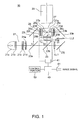
- Fig. 1 is a view showing optical system of the projector of the first embodiment.
- the projector 10 includes: a light source device 21 to generate light-source light; a light division optical system 23 to split light-source light from the light source device 21 into beams of light for three colors of RGB; a light modulation portion 25 illuminated by beams of illumination light of respective colors emitted from the light division optical system 23; a cross dichroic prism 27 to synthesize images of light of respective colors from the light modulation portion 25; and a projection lens 29 serving as a projection optical system to project images of light synthesized in the cross dichroic prism 27 onto a screen (not shown).
- the projector 10 includes an image processing portion 40 to generate driving signals for display devices of respective colors (described below) incorporated in the light modulation portion 25, and a control device 50 to control the overall apparatus systematically by activating the image processing portion 40 or the like as needed.
- the light source device 21 includes a light source lamp 21a, a pair of fly's eye optical systems 21b and 21c, a polarization converting member 21d, and a superimposing lens 21e.
- the light source lamp 21a comprises, for example, a high-pressure mercury lamp and is provided with a concave mirror to collimate light-source light.
- the pair of fly's eye optical systems 21b and 21c comprises a plurality of element lenses placed in a matrix fashion, and these element lenses split light-source light from the light source lamp 21a to be condensed or dispersed independently.
- the polarization converting member 21d converts light-source light emitted from the fly's eye 21c, for example, to S-polarized light components alone, which are perpendicular to the sheet surface of FIG. 1, and feeds them to an optical system in the following stage.
- the superimposing lens 21e converges illumination light as a whole that has passed through the polarization converting member 21d as needed, and thereby enables superimposed illumination by the display devices of respective colors.
- illumination light having passed through the both fly's eye optical systems 21b and 21c and the superimposing lens 21e, passes through the light division optical system 23 and thereby achieves homogeneous, superimposed illumination on display devices 25a, 25b, and 25c of respective colors provided to the light modulation portion 25, which will be described in detail below.
- the light division optical system 23 includes first and second dichroic mirrors 23a and 23b, three field lenses 23f, 23g, and 23h, and reflection mirrors 23i, 23j, and 23k, and forms an illuminating device together with the light source device 21.
- the first dichroic mirror 23a reflects R light and transmits G light and B light.
- the second dichroic mirror 23b reflects G light and transmits B light.
- R light reflected on the first dichroic mirror 23a passes through the reflection mirror 23i, and then goes incident on the field lens 23f used to regulate an angle of incidence in the form of S-polarized light, after which it is converted to P-polarized light from S-polarized light by passing through a ⁇ /2 phase difference plate 23d.
- G light having passed through the first dichroic mirror 23a and reflected on the second dichroic mirror 23b, passes through a neutral density filter 31 of a parallel plate shape, and then goes incident on the field lens 23g used to regulate an angle of incidence.
- B light having passed through the second dichroic mirror 23b, passes through relay lenses LL1 and LL2 to compensate a difference of optical paths and the reflection mirrors 23j and 23k, and then goes incident on the field lens 23h used to regulate an angle of incidence in the form of S-polarized light, after which it is converted to P-polarized light from S-polarized light by passing through the ⁇ /2 phase difference plate 23d.
- R light, B light, and G light are composed of different beams of polarized light. It should be appreciated, however, that R light, B light, and G light may be composed of the same beams of polarized light.
- the neutral density filter 31 comprises a parallel plate made of glass, on one surface of which is uniformly formed a dielectric multi-layer film, and has desired transmittance with respect to G light. Because the neutral density filter 31 is a filter of a reflective type using a dielectric multi-layer film, it does not absorb light when reducing light. Hence, the temperature rises little, but unwanted reflection light is generated as a byproduct. Although it will be described in detail below, such by-productive reflection light can be released to the outside of the light path by tilting the neutral density filter 31 by a minute angle with respect to the optical axis, which can prevent the reflection light from resulting in stray light. An angle of tilt of the neutral density filter 31 can be fine-adjusted by a posture regulating mechanism 33 serving as holding means. It is thus possible to fine-adjust a degree of reduction of light by the neutral density filter 31.
- the display devices 25a, 25b, and 25c of respective colors that form the light modulation portion 25 include three liquid crystal light valves 26a, 26b, and 26c, respectively, each serving as a light modulation device.
- R light, reflected on the first dichroic mirror 23a goes incident on the liquid crystal light valve 26a provided to the R display device 25a via the field lens 23f and the ⁇ /2 phase difference plate 23d.
- Each of the liquid crystal light valves 26a through 26c is a display device of a spatial light modulation type that modulates a spatial intensity distribution of incident illumination light. Beams of illumination light of three colors that come incident on the liquid crystal light valves 26a through 26c, respectively, are modulated according to a driving signal or an image signal inputted as an electric signal to each of the liquid crystal light valves 26a through 26c.
- the cross dichroic prism 27 is a light synthesizing member, having inside a dielectric multi-layer film 27a for reflecting R light and a dielectric multi-layer film 27b for reflecting B light that intersect with each other at right angles.
- R light from the R display device 25a is reflected on the dielectric multi-layer film 27a to be emitted to the right in a travel direction.
- G light from the G display device 25b is emitted to travel straight via the dielectric multi-layer films 27a and 27b.
- B light from the B display device 25c is reflected on the dielectric multi-layer film 27b to be emitted to the left in a travel direction.
- the image processing portion 40 operates as per instructions from the control device 50 that systematically controls the operations of the overall projector 10, to which digital image signals from a personal computer and video image signals from a video player or the like are inputted via a connector 61.
- the image processing portion 40 converts these image signals into control signals to activate the respective liquid crystal light valves 26a through 26c as needed, and outputs the control signals to a liquid crystal driving portion 41.
- the liquid crystal driving portion 41 outputs driving signals needed for pixel-by-pixel display operations by the respective liquid crystal light valves 26a through 26c to each of the liquid crystal light valves 26a through 26c. It is thus possible to form 2-D polarization characteristic distributions, corresponding to luminance of respective colors in a projection image, in the respective liquid crystal light valves 26a through 26c.
- FIG. 2 is a view showing the concrete placement of the light modulation portion 25 and optical components on the periphery.
- a first polarization filter 26e is placed on the light incident side of the liquid crystal light valve 26b so as to oppose the light incident surface, which makes it possible to illuminate exactly the liquid crystal light valve 26b with polarized components in a specific direction (to be specific, S-polarized light).
- a second polarization filter 26f is placed on the light emission side of the liquid crystal light valve 26b so as to oppose the light emission surface, which makes it possible to read out only polarized components having passed through the liquid crystal light valve 26b, in a direction that intersects with the specific direction at right angles.
- a optical compensating element is placed in a space between the liquid crystal light valve 26b and the second polarized filter 26f. Hence, when an electric field is formed in the liquid crystal layer, a phase difference remaining on the light incident side and the light emission side is compensated, and the display at the black level is thereby increased.
- the R display device 25a and the B display device 25c have the same structure as the G display device 25b except that the ⁇ /2 phase difference plate 23d is additionally interposed.
- the neutral density filter 31 is placed in the preceding stage of the field lens 23g on the G light emission side of the second dichroic mirror 23b.
- a tilting angle of the neutral density filter 31 with respect to the optical axis OA can be adjusted by means of the posture regulating mechanism 33.
- the posture regulating mechanism 33 includes a pivoted member 34 to pivotally support the neutral density filter 31 at one end, and a fixing device 35 to fix the neutral density filter 31 at the other end.
- the neutral density filter 31 held by the posture regulating mechanism 33 is supported by the pivoted member 34, and is in a state tilted, for example, by about 8° with respect to the optical axis OA.
- An angle of tilt can be fine-adjusted about the angle of 8° by the settings of the fixing device 35.
- an angle of tilt of the neutral density filter 31 even in a case where the provided dielectric multi-layer film per se has irregularities in transmittance or in a case where transmittance varies due to aberration, absorption, etc. of the optical system up to the neutral density filter 31, not only can targeted white balance be achieved, but also a high-quality image can be projected by canceling out these irregularities in transmittance.
- FIG. 3 is a perspective view showing the posture regulating mechanism 33.
- the posture regulating mechanism 33 comprises the pivoted member 34 to hold a frame 37 that holds the neutral density filter 31 rotatably about an axis AX1 perpendicular to the optical axis OA at the basal, which is the side portion of the frame 37, and the fixing device 35 to fix the tip end on the side of the frame 37 to allow displacement.
- the latter fixing device 35 includes a stay 35a fixedly attached to an unillustrated main body member on the tip end of the frame 37, and a screw 35b screwed into a female screw member 37a through a long hole 35f provided in the stay 35a.
- the neutral density filter 31 is in a state tilted by about 8° with respect to the optical axis OA.
- the screw 35b is screwed into the female screw member 37a and tightened in this state, the stay 35a and the female screw member 37a are fixed to each other, and the frame 37, that is, the neutral density filter 31, is held while being tilted by about 8° to 15° with respect to the optical axis OA.
- the screw 35b is loosened from the female screw member 37a
- the female screw member 37a is allowed to move with respect to the stay 35a, and the frame 37, that is, the neutral density filter 31, rotates about the axis AX1 as the axis of rotation.
- FIG. 4 is a perspective view showing the modification of the posture regulating mechanism 33.
- the posture regulating mechanism 33 comprises a pivoted member 134 to support the frame 37 that holds the neutral density filter 31 rotatably about an axis AX2 perpendicular to the optical axis OA at the basal, which is the bottom portion of the frame 37, and a fixing device 135 to fix the tip end on the upper side of the frame 37 to allow displacement.
- the latter fixing device 135 includes a stay 135a fixedly attached to an unillustrated main body member at the tip end of the frame 37, and a screw 135b screwed into a female screw member 137a through a long hole 135f provided in the stay 135a.
- the neutral density filter 31 is in a state tilted by about 8° with respect to the optical axis OA.
- the screw 135b is screwed into the female screw member 137a and tightened in this state, the stay 135a and the female screw member 137a are fixed to each other, and the frame 37, that is, the neutral density filter 31, is held while being tilted by about 8° to 15° with respect to the optical axis OA.
- the screw 135b is loosened from the female screw member 137a
- the female screw member 137a is allowed to move with respect to the stay 135a, and the frame 37, that is, the neutral density filter 31, rotates about the axis AX2 as the axis of rotation.
- FIG. 5 is a graph to explain the simulation result of angle independency of transmittance of the neutral density filter 31.
- the abscissa is used for a wavelength (nm) and the ordinate is used for transmittance (%).
- an angle of tilt of the neutral density filter 31 is determined by pre-setting the wavelength and a target light-reducing ratio of illumination light (G light in this embodiment) passing through the neutral density filter 31.
- Table 1 set forth below shows the result when a change in transmittance of the neutral density filter 31 was measured by fine-adjusting an angle of tilt of the neutral density filter 31.
- FIG. 6 is a graph to explain a relation of a tilt of the neutral density filter 31 and a luminance distribution.
- the abscissa is used for positions on the neutral density filter 31, and the ordinate is used for apparent transmittance at respective positions.
- transmittance that is, luminance of a projection image
- transmittance that is, luminance of the projection image
- transmittance that is, luminance of a projection image
- transmittance is made homogeneous at the center and the both ends.
- the neutral density filter 31 is tilted by a predetermined angle or greater with respect to the optical axis, it is possible to prevent a phenomenon that illumination light concentrates at the center of the screen and the center of a projection image becomes brighter, that is, the occurrence of greenish irregularities in color at the center of a projection image.
- Table 2 set forth below is a table to explain a change of measured values of transmittance when angles of tilt for a plurality of neutral density filters 31 are set as needed.
- filter 1 and filter 2 mean that separate filters each having different transmittance are used as the neutral density filter 31.
- rows titled “center”, “right end”, and “left end” indicate transmittance corresponding to respective positions on the screen.
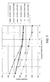
- FIG. 7 is a graph when the measured values of Table 2 are plotted.
- the abscissa is used for an angle of tilt of the neutral density filter 31, and the ordinate is used for apparent transmittance at respective positions.
- transmittance across the entire surface became almost equal when an angle of tilt of these filters was 8° or greater.
- FIG. 8 is a view showing the relation of the posture of the neutral density filter 31 and a transmittance distribution.
- FIG. 8(a) is a view to explain an illumination characteristic when the neutral density filter 31 is not tilted at all.
- FIG. 8(b) is a view to explain an illumination characteristic when the neutral density filter 31 is tilted as needed.
- the neutral density filter 31 in a case where the neutral density filter 31 is placed so as to intersect with the optical axis OA at right angles, because the field lens 23f having positive power is placed in the latter stage of the neutral density filter 31 on which initial illumination light L1 goes incident, return light L2, reflected on the liquid crystal light valve 26b, the first polarization filter 26e, etc. as unwanted light, is condensed by means of the field lens 23f and then goes incident on the neutral density filter 31.
- the neutral density filter 31 allows stray light L3 to go incident again on the field lens 23f while condensing return light L2 by reflection. A degree of convergence of stray light L3 that goes incident on the field lens 23f is greater than a degree of convergence of the initial illumination light L1.
- Stray light L3 thus becomes able to illuminate the liquid crystal light valve 26b at a central region alone. Multi-reflection takes place while such phenomena are repeated, which causes illumination at the central region to intensify.
- luminance is increased at the center of the screen, but light is reduced on the periphery (see a dotted line on the graph of FIG. 6). That is to say, of the entire image projected onto the screen, brightness of G is increased at the central portion, which is equivalent to the occurrence of irregularities in color when viewed entirely.
- an image of G light has homogeneous brightness across the entire screen (see the solid line of FIG. 6). In short, it is possible to project an image having no irregularities in color across the entire screen.
- Light-source light from the light source device 21 is split into beams of light according to colors by the first and second dichroic mirrors 23a and 23b provided in the light division optical system 23, and these beams of light go incident on the corresponding liquid crystal light valves 26a through 26c as illumination light.
- the respective liquid crystal light valves 26a through 26c are modulated by image signals from the outside and have 2-D refractive index distributions, thereby modulating illumination light 2-D spatially pixel by pixel.
- Beams of illumination light, that is, images of light, modulated by the respective liquid crystal light valves 26a through 26c are synthesized in the cross dichroic prism 27, and then go incident on the projection lens 29.
- the images of light that come incident on the projection lens 29 are projected onto the unillustrated screen.
- the neutral density filter 31, of which posture can be fine-adjusted by means of the posture regulating mechanism 33 is placed in a space between the second dichroic mirror 23b and the liquid crystal light valve 26b, it is possible to remove stray light, which corresponds to condensed light resulted from multi-pass through the field lens 23f or the like, to the outside of the light path in a reliable manner by merely tilting the neutral density filter 31 adequately. It is thus possible to project an image having homogeneous brightness (illuminance at the white level) across the entire screen, which in turn makes it possible to project an image having no irregularities in color across the entire screen.
- a projector according to a second embodiment is a projector employing a digital mirror device (DMD) comprising a light-modulating element of a reflective type.
- DMD digital mirror device
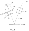
- FIG. 9 is a view showing the optical system of the projector of the second embodiment.
- the projector 210 comprises a light source device 221, a color wheel 271, a neutral density filter 231, a digital mirror device (DMD) 225, and a projection lens 229, which are placed sequentially along a system optical axis SA.
- DMD digital mirror device
- the light source device 221 comprises a light source lamp and a reflector.
- Light-source light from the light source device 221 goes incident on the color wheel 271 and is split into beams of illumination light of respective colors that switch with time by passing through the color wheel 271, which go incident on the digital mirror device 225 by way of the neutral density filter 231.
- the digital mirror device 225 is a spatial light-modulating device of a reflection direction control type furnished with a function of emitting image light representing an image in a direction to the projection lens 229, by reflecting incident beams of illumination light of respective colors on micro mirrors corresponding to respective pixels according to image signals. Image light emitted from the digital mirror device 225 is projected onto a screen (not shown) by means of the projection lens 229.
- the neutral density filter 231 is used to adjust color balance and luminance.
- the neutral density filter 231 is held by the posture regulating mechanism 33 in a state tilted by a minute angle with respect to the system optical axis SA. It is thus possible to release stray light that causes irregularities in color to the outside of the light path.
- the position of the neutral density filter 31 is not limited to somewhere between the second dichroic mirror 23b and the liquid crystal light valve 26b, and can be somewhere between the first dichroic mirror 23a and the second dichroic mirror 23b or somewhere between the first dichroic mirror 23a and the light source device 121.
- the neutral density filter 31 can be placed not only in a space between the second dichroic mirror 23b and the liquid crystal light valve 26b, but also in the preceding stages of the other liquid crystal light valves 26a and 26c.
- the projector 10 may be configured in such a manner that light-source light from a white light source is condensed by a mirror or the like to go incident on the light incident end of a rod integrator in obtaining homogeneous illumination light at the light emission end of the rod integrator, so that a single liquid crystal light valve of a color display type, placed oppositely to the light emission end of the rod integrator, is directly illuminated by the illumination light thus obtained.
- a single liquid crystal light valve of a color display type placed oppositely to the light emission end of the rod integrator
Landscapes
- Physics & Mathematics (AREA)
- General Physics & Mathematics (AREA)
- Engineering & Computer Science (AREA)
- Multimedia (AREA)
- Signal Processing (AREA)
- Projection Apparatus (AREA)
- Liquid Crystal (AREA)
- Transforming Electric Information Into Light Information (AREA)
Applications Claiming Priority (2)
| Application Number | Priority Date | Filing Date | Title |
|---|---|---|---|
| JP2003379912 | 2003-11-10 | ||
| JP2003379912A JP4141938B2 (ja) | 2003-11-10 | 2003-11-10 | プロジェクタ |
Publications (2)
| Publication Number | Publication Date |
|---|---|
| EP1530378A2 true EP1530378A2 (fr) | 2005-05-11 |
| EP1530378A3 EP1530378A3 (fr) | 2007-01-24 |
Family
ID=34431388
Family Applications (1)
| Application Number | Title | Priority Date | Filing Date |
|---|---|---|---|
| EP04256856A Withdrawn EP1530378A3 (fr) | 2003-11-10 | 2004-11-05 | Projecteur |
Country Status (6)
| Country | Link |
|---|---|
| US (1) | US7168812B2 (fr) |
| EP (1) | EP1530378A3 (fr) |
| JP (1) | JP4141938B2 (fr) |
| KR (1) | KR100691071B1 (fr) |
| CN (1) | CN100390659C (fr) |
| TW (1) | TWI287165B (fr) |
Cited By (1)
| Publication number | Priority date | Publication date | Assignee | Title |
|---|---|---|---|---|
| CN102081285B (zh) * | 2009-11-27 | 2012-07-04 | 中强光电股份有限公司 | 调整装置及具有该调整装置的投影机 |
Families Citing this family (14)
| Publication number | Priority date | Publication date | Assignee | Title |
|---|---|---|---|---|
| KR20040091730A (ko) * | 2002-03-14 | 2004-10-28 | 코닌클리케 필립스 일렉트로닉스 엔.브이. | 모드 선택 유닛을 가진 프로젝션 디바이스 |
| KR101120601B1 (ko) | 2004-04-01 | 2012-03-16 | 뮤젼 시스템즈 리미티드 | 페퍼스 고스트 환상용 투사 장치 및 방법 |
| JP4645371B2 (ja) * | 2005-09-01 | 2011-03-09 | セイコーエプソン株式会社 | プロジェクタ |
| WO2007056595A1 (fr) * | 2005-11-09 | 2007-05-18 | Thomson Licensing | Regleur de couture optique |
| KR100707860B1 (ko) * | 2005-12-21 | 2007-04-17 | 주식회사 이오테크닉스 | 레이저 빔을 이용한 비아홀 형성방법 |
| JP2007322923A (ja) * | 2006-06-02 | 2007-12-13 | Sharp Corp | 光学装置及び投射型表示装置 |
| JP5648368B2 (ja) | 2010-08-23 | 2015-01-07 | ミツミ電機株式会社 | 光走査装置 |
| JP5861324B2 (ja) * | 2011-08-30 | 2016-02-16 | セイコーエプソン株式会社 | プロジェクター、及び、プロジェクターの制御方法 |
| TWI456333B (zh) * | 2013-03-28 | 2014-10-11 | Delta Electronics Inc | 適用於數位電影投影裝置之光源系統 |
| WO2017179655A1 (fr) * | 2016-04-15 | 2017-10-19 | 日本精機株式会社 | Écran de transmission et dispositif d'affichage à balayage laser |
| JP6946650B2 (ja) * | 2017-02-01 | 2021-10-06 | セイコーエプソン株式会社 | 光源装置及びプロジェクター |
| JP7081256B2 (ja) * | 2018-03-27 | 2022-06-07 | セイコーエプソン株式会社 | 光学ユニット、および表示装置 |
| CN111352287A (zh) * | 2018-12-24 | 2020-06-30 | 深圳光峰科技股份有限公司 | 光源系统及投影设备 |
| CN111323998B (zh) * | 2020-03-13 | 2021-12-03 | 聊城市坚果教育科技有限公司 | 一种可调节的高光度多媒体投放平台 |
Family Cites Families (20)
| Publication number | Priority date | Publication date | Assignee | Title |
|---|---|---|---|---|
| JPH02293732A (ja) * | 1989-05-08 | 1990-12-04 | Matsushita Electric Ind Co Ltd | 投写型表示装置 |
| JPH03221914A (ja) * | 1990-01-29 | 1991-09-30 | Ricoh Co Ltd | 光書込み装置 |
| JP2934737B2 (ja) * | 1991-02-15 | 1999-08-16 | 株式会社半導体エネルギー研究所 | 表示装置およびその表示方法 |
| JP3015201B2 (ja) * | 1992-05-06 | 2000-03-06 | キヤノン株式会社 | 画像形成装置、投射型表示装置並びに光変調装置 |
| KR100330109B1 (ko) * | 1994-06-17 | 2002-11-22 | 똥송 쎄에스에프 | 광학필터링장치및액정프로젝터 |
| KR970045345A (ko) * | 1995-12-14 | 1997-07-26 | 김태구 | 시동 스위치 어셈블리(Astarting switch assembly) |
| KR100207681B1 (ko) * | 1996-05-23 | 1999-07-15 | 윤종용 | 프로젝터용 화상투사장치 |
| US6111700A (en) * | 1996-09-05 | 2000-08-29 | Fujitsu Limited | Optical display device having a reflection-type polarizer |
| US6650357B1 (en) * | 1997-04-09 | 2003-11-18 | Richardson Technologies, Inc. | Color translating UV microscope |
| JPH10311968A (ja) | 1997-05-13 | 1998-11-24 | Sony Corp | 液晶プロジェクタ |
| JP2001100311A (ja) * | 1999-07-23 | 2001-04-13 | Seiko Epson Corp | プロジェクタ |
| JP2001092419A (ja) * | 1999-09-22 | 2001-04-06 | Canon Inc | 表示装置 |
| KR100364399B1 (ko) * | 2000-10-26 | 2002-12-12 | 엘지전자 주식회사 | 액정 프로젝터의 광학계 |
| JP4776785B2 (ja) | 2001-01-12 | 2011-09-21 | キヤノン株式会社 | 投射型表示装置 |
| JP2002277820A (ja) * | 2001-03-22 | 2002-09-25 | Fuji Photo Optical Co Ltd | 照明光学系およびこれを用いた投写型カラー画像表示装置 |
| JP2003114480A (ja) * | 2001-10-04 | 2003-04-18 | Seiko Epson Corp | プロジェクタの光学系の変更に応じた画像処理 |
| CN2510883Y (zh) * | 2001-12-28 | 2002-09-11 | 北京澳柯玛视美乐信息技术有限公司 | 反射式硅基液晶投影机光学机构 |
| JP3693959B2 (ja) * | 2002-01-10 | 2005-09-14 | Necビューテクノロジー株式会社 | ディスプレイシステム |
| JP2003295318A (ja) * | 2002-04-08 | 2003-10-15 | Plus Vision Corp | プロジェクタ |
| KR100518869B1 (ko) * | 2002-12-31 | 2005-10-04 | 엘지전자 주식회사 | 엘씨디 프로젝터의 편광판 위치 조정 장치 |
-
2003
- 2003-11-10 JP JP2003379912A patent/JP4141938B2/ja not_active Expired - Fee Related
-
2004
- 2004-11-04 US US10/980,330 patent/US7168812B2/en not_active Expired - Fee Related
- 2004-11-05 EP EP04256856A patent/EP1530378A3/fr not_active Withdrawn
- 2004-11-09 TW TW093134137A patent/TWI287165B/zh not_active IP Right Cessation
- 2004-11-09 KR KR1020040091004A patent/KR100691071B1/ko not_active Expired - Fee Related
- 2004-11-10 CN CNB2004100909453A patent/CN100390659C/zh not_active Expired - Fee Related
Cited By (1)
| Publication number | Priority date | Publication date | Assignee | Title |
|---|---|---|---|---|
| CN102081285B (zh) * | 2009-11-27 | 2012-07-04 | 中强光电股份有限公司 | 调整装置及具有该调整装置的投影机 |
Also Published As
| Publication number | Publication date |
|---|---|
| CN100390659C (zh) | 2008-05-28 |
| CN1617043A (zh) | 2005-05-18 |
| JP4141938B2 (ja) | 2008-08-27 |
| US20050128439A1 (en) | 2005-06-16 |
| TW200527112A (en) | 2005-08-16 |
| KR20050045863A (ko) | 2005-05-17 |
| KR100691071B1 (ko) | 2007-03-09 |
| US7168812B2 (en) | 2007-01-30 |
| EP1530378A3 (fr) | 2007-01-24 |
| JP2005141152A (ja) | 2005-06-02 |
| TWI287165B (en) | 2007-09-21 |
Similar Documents
| Publication | Publication Date | Title |
|---|---|---|
| US6402325B1 (en) | Illuminating optical system having multiple light sources and lenticular arrays for use with a projection-type display unit | |
| EP1530378A2 (fr) | Projecteur | |
| JP4144624B2 (ja) | プロジェクタ | |
| JP2002023106A (ja) | 照明光学系およびこれを備えたプロジェクタ | |
| US6712473B2 (en) | Mirror array device and projection type display apparatus using the same | |
| JP4144623B2 (ja) | プロジェクタ | |
| US7329007B2 (en) | Projector | |
| US8025411B2 (en) | Liquid crystal panel and projector using the same | |
| US20040125274A1 (en) | Image display apparatus | |
| CN100460992C (zh) | 投影机 | |
| TW200537235A (en) | Projector | |
| JP4631422B2 (ja) | プロジェクタ | |
| JP2005106983A (ja) | プロジェクタ | |
| JPH0372332A (ja) | 投写型カラー表示装置 | |
| US12432323B2 (en) | Optics for projection display | |
| JP4609028B2 (ja) | プロジェクタ | |
| JP4036123B2 (ja) | プロジェクタ | |
| JP2822114B2 (ja) | 投写型液晶ディスプレイ | |
| JP4543680B2 (ja) | 照明光学系 | |
| JP2006084618A (ja) | プロジェクタ | |
| JP2009237091A (ja) | プロジェクタ | |
| JP2008134276A (ja) | プロジェクタ | |
| JP2007264245A (ja) | プロジェクタ | |
| JP2000180793A (ja) | 映像表示装置 | |
| JP2009086400A (ja) | プロジェクタ |
Legal Events
| Date | Code | Title | Description |
|---|---|---|---|
| PUAI | Public reference made under article 153(3) epc to a published international application that has entered the european phase |
Free format text: ORIGINAL CODE: 0009012 |
|
| AK | Designated contracting states |
Kind code of ref document: A2 Designated state(s): AT BE BG CH CY CZ DE DK EE ES FI FR GB GR HU IE IS IT LI LU MC NL PL PT RO SE SI SK TR |
|
| AX | Request for extension of the european patent |
Extension state: AL HR LT LV MK YU |
|
| PUAL | Search report despatched |
Free format text: ORIGINAL CODE: 0009013 |
|
| AK | Designated contracting states |
Kind code of ref document: A3 Designated state(s): AT BE BG CH CY CZ DE DK EE ES FI FR GB GR HU IE IS IT LI LU MC NL PL PT RO SE SI SK TR |
|
| AX | Request for extension of the european patent |
Extension state: AL HR LT LV MK YU |
|
| 17P | Request for examination filed |
Effective date: 20070712 |
|
| AKX | Designation fees paid |
Designated state(s): DE FR GB |
|
| 17Q | First examination report despatched |
Effective date: 20080218 |
|
| GRAP | Despatch of communication of intention to grant a patent |
Free format text: ORIGINAL CODE: EPIDOSNIGR1 |
|
| STAA | Information on the status of an ep patent application or granted ep patent |
Free format text: STATUS: THE APPLICATION IS DEEMED TO BE WITHDRAWN |
|
| 18D | Application deemed to be withdrawn |
Effective date: 20100223 |