EP1528816A2 - BILDERFASSUNGSfCEINRICHTUNG UND VERFAHREN - Google Patents
BILDERFASSUNGSfCEINRICHTUNG UND VERFAHREN Download PDFInfo
- Publication number
- EP1528816A2 EP1528816A2 EP04256429A EP04256429A EP1528816A2 EP 1528816 A2 EP1528816 A2 EP 1528816A2 EP 04256429 A EP04256429 A EP 04256429A EP 04256429 A EP04256429 A EP 04256429A EP 1528816 A2 EP1528816 A2 EP 1528816A2
- Authority
- EP
- European Patent Office
- Prior art keywords
- white balance
- filter
- ratio
- image pickup
- video signals
- Prior art date
- Legal status (The legal status is an assumption and is not a legal conclusion. Google has not performed a legal analysis and makes no representation as to the accuracy of the status listed.)
- Withdrawn
Links
Images


Classifications
-
- H—ELECTRICITY
- H04—ELECTRIC COMMUNICATION TECHNIQUE
- H04N—PICTORIAL COMMUNICATION, e.g. TELEVISION
- H04N9/00—Details of colour television systems
- H04N9/64—Circuits for processing colour signals
- H04N9/73—Colour balance circuits, e.g. white balance circuits or colour temperature control
-
- H—ELECTRICITY
- H04—ELECTRIC COMMUNICATION TECHNIQUE
- H04N—PICTORIAL COMMUNICATION, e.g. TELEVISION
- H04N23/00—Cameras or camera modules comprising electronic image sensors; Control thereof
- H04N23/80—Camera processing pipelines; Components thereof
- H04N23/84—Camera processing pipelines; Components thereof for processing colour signals
- H04N23/88—Camera processing pipelines; Components thereof for processing colour signals for colour balance, e.g. white-balance circuits or colour temperature control
Definitions
- the present invention relates to a device and a method for image pickup.
- Embodiments of the present invention relate to a device and a method for image pickup that can perform white balance control according to whether an infrared cut filter is present or not.
- a digital video camera which selectively switches an infrared cut filter to a position on an optical axis of a lens group and a position off the optical axis so that the digital video camera can be used for both picture taking using near-infrared light and picture taking using visible light (see for example Patent Document 1).
- gray balance adjustment Adjustment of a color balance of a camera is referred to as white balance adjustment.
- a method is proposed which controls an RGB integral ratio to 1:1:1 on the basis of a hypothesis that a spatial average of reflectance of a surface of an object in a scene is close to gray (hereinafter referred to as gray world control).
- This gray world control is detailed in a document of G. Buchesbaum, "A Spatial Processor Model for Object Color Perception," J. FranklinInst., 310, 1980.
- blackbody curve control a method which performs control such that a ratio between respective integral values of an R component, a G component, and a B component of an entire screen is the same as an RGB ratio of blackbody curve data L as shown in FIG. 1 (hereinafter referred to as blackbody curve control).
- an axis of ordinates indicates ratio (B/G) between the integral values of the B component and the G component
- an axis of abscissas indicates ratio (R/G) between the integral values of the R component and the G component.
- the blackbody curve data L indicates ratios between primary color signals R, G, and B based on a white subject taken under a light source at various color temperatures, and represents a curve such that as one of the ratios is increased, the other ratio is decreased. Also, the color temperature rises as the B/G ratio is increased, and the color temperature falls as the R/G ratio is increased. In the example of FIG. 1, integral value ratios when the color temperature is 7500 K, 5800 K, and 3200 K, respectively, are plotted. Details of the blackbody curve control are disclosed in Japanese Patent Publication No. 2751297.
- the gray world control assumes that there is no color deviation within a screen. When there is a color deviation, a white balance is disturbed greatly. On the other hand, the blackbody curve control has an advantage of not readily causing a shift in the white balance even when there is a color deviation. Thus the blackbody curve control is now a mainstream white balance system.
- rays of light including the infrared rays redden an entire screen.
- FIG. 2 is a flowchart of assistance in explaining a process of selectively switching between a time of normal picture taking and a time of night-shot picture taking and performing white balance control.
- step S1 the digital video camera determines whether the infrared cut filter is disposed on the optical axis of the lens group, that is, whether a mode of picture taking under normal visible light is set according to a user instruction.
- the process proceeds to step S2, where the digital video camera performs blackbody curve control so that a ratio between respective integral values of an R component, a G component, and a B component of an entire screen becomes the same as the RGB ratio of the blackbody curve data L shown in FIG. 1.
- step S1 when the digital video camera determines in step S1 that the infrared cut filter is not disposed on the optical axis of the lens group, that is, that a mode of night-shot picture taking under light including infrared light is set according to a user instruction, the process proceeds to step S3, where the digital video camera performs control to make the entire screen a monotone screen for output.
- the digital video camera controls the white balance of the camera according to picture taking conditions at the time of normal picture taking and the time of night-shot picture taking, for example.
- Patent Document 2 is effective for a vehicle-mounted camera, a front-door intercom camera or the like that assumes outdoor picture taking, but is not suitable for digital cameras that need to take pictures under various light sources such as fluorescent lamps, incandescent lamps and the like.
- Embodiments of the present invention seek to realize natural color reproduction of a camera at a time of picture taking under light including an infrared component.
- an image pickup device comprising: a detecting unit configured to detect a position of a filter for changing light separation; and a white balance controlling unit configured to perform white balance control on a basis of the position of the filter detected by the detecting unit.
- the white balance controlling unit may perform control such that a ratio between integral values of video signals obtained by picture taking becomes a ratio between integral values of video signals based on a white subject.
- the white balance controlling unit may perform control such that a ratio between integral values of video signals obtained by picture taking becomes one.
- the controlling unit may perform control such that a ratio between integral values of a high-luminance portion of the video signals becomes one.
- the controlling unit may perform control such that a ratio between integral values of a predetermined luminance range portion of the video signals becomes one.
- the white balance controlling unit may perform control such that a ratio between integral values of video signals obtained by picture taking becomes a ratio between integral values of video signals based on a white subject taking an infrared component into consideration.
- the white balance controlling unit may avoid performing low-illuminance achromatization.
- an image pickup method comprising the steps of: detecting a position of a filter for changing light separation; and performing white balance control on a basis of the position of the filter detected by a process of the detecting step.
- an image pickup device comprising: detecting means for detecting a position of a filter for changing light separation; and white balance controlling means for performing white balance control on a basis of the position of the filter detected by the detecting means.
- a position of a filter for changing light separation is detected, and white balance control is performed on a basis of the detected position of the filter.
- Embodiments of the present invention provide an image pickup device (for example a video camera in FIGS. 3 to 6) comprising: a detecting unit (for example a microcomputer 58 in FIG. 6 that performs a process of step S11 in FIG. 10, step S21 in FIG. 11, step S31 in FIG. 12, or step S41 in FIG. 13) configured to detect a position of a filter for changing light separation; and a white balance controlling unit (for example the microcomputer 58 in FIG. 6 that performs a process of steps S13 and S15 in FIG. 10, steps S23 and S25 in FIG. 11, steps S33 and S35 in FIG. 12, or steps S43 and S45 in FIG. 13) configured to perform white balance control on a basis of the position of the filter detected by the detecting unit.
- a detecting unit for example a microcomputer 58 in FIG. 6 that performs a process of step S11 in FIG. 10, step S21 in FIG. 11, step S31 in FIG. 12, or step S41 in FIG. 13
- the white balance controlling unit can perform control such that a ratio between integral values of video signals obtained by picture taking becomes a ratio of integral values of video signals based on a white subject (for example becomes the same as an RGB ratio of blackbody curve data LA in FIG. 9).
- the white balance controlling unit can perform control such that a ratio between integral values of video signals obtained by picture taking becomes one.
- the controlling unit can perform control such that a ratio between integral values of a high-luminance portion of the video signals becomes one.
- the controlling unit can perform control such that a ratio between integral values of a predetermined luminance range portion of the video signals becomes one.
- the white balance controlling unit can perform control such that a ratio between integral values of video signals obtained by picture taking becomes a ratio between integral values of video signals based on a white subject taking an infrared component into consideration (for example becomes the same as an RGB ratio of blackbody curve data LB obtained by taking an infrared component into consideration in FIG. 9).
- the white balance controlling unit can avoid performing low-illuminance achromatization.
- embodiments of the present invention provide an image pickup method, comprising the steps of: detecting a position of a filter for changing light separation (for example step S11 in FIG. 10, step S21 in FIG. 11, step S31 in FIG. 12, or step S41 in FIG. 13); and performing white balance control on a basis of the position of the filter detected by a process of the detecting step (for example steps S13 and S15 in FIG. 10, steps S23 and S25 in FIG. 11, steps S33 and S35 in FIG. 12, or steps S43 and S45 in FIG. 13).
- FIGS. 3 to 5 are diagrams showing an example of structure of a video camera 1 of an embodiment of the present invention.
- FIG. 3 is a perspective external view of the video camera 1.
- FIG. 4 is a sectional view taken along a line A-A shown in FIG. 3 (a sectional view of a lens block of the video camera 1).
- FIG. 5 is an exploded perspective view of a link device.
- the video camera 1 comprises: a camera mechanism unit configured to capture an image of a subject as light and convert the optical image into an electric signal; a video mechanism unit configured to record the electric signal from the camera mechanism unit and reproduce the recorded electric signal; and a camera exterior body 2, as a cabinet, configured to house the camera mechanism unit and the video mechanism unit.
- the camera mechanism unit comprises for example: a lens group 51 (FIG. 6) including an objective lens 3 opposed to a subject, configured to transmit an optical image of the subject which image is made incident as light from the objective lens 3, and form the image on a light receiving unit; an image pickup element 54 (FIG. 6) configured to convert the optical image transmitted by the lens group 51 and formed on the light receiving unit into an electric signal; a viewfinder 4 configured to view the image captured by the objective lens 3 with an eye; and a control unit (not shown) configured to control driving of a motor for focusing the lens group 51, adjusting an amount of iris opening and the like.
- a lens hole 2a is provided in an upper part of a front of the camera exterior body 2.
- a lens block 5 comprising the lens group 51 including an autofocus mechanism, a zoom mechanism and the like, and a block casing 11 for fixedly or movably holding the lens group 51 is disposed inside the lens hole 2a.
- the objective lens 3 placed at the front of the lens block 5 is exposed in the lens hole 2a.
- An infrared cut filter 21 (FIG. 4) is disposed between the lens group 51 and the image pickup element 54.
- a filter holding link 23 is rotatably supported on a rotating shaft 22 disposed in the block casing 11 of the lens block 5.
- the filter holding link 23 has an arm portion 23a with a bearing hole at an intermediate part thereof in which bearing hole the rotating shaft 22 is rotatably fitted, and a filter holding portion 23b in a form of a ring formed continuously at one end of the arm portion 23a.
- the infrared cut filter 21 is fixed to the filter holding portion 23b.
- the infrared cut filter 21 fixed to the filter holding link 23 is formed such that a center of the infrared cut filter 21 in a free state of being held by fitting and hung on the rotating shaft 22 is positioned on an optical axis of the lens group 51.
- An input portion 23c formed into a forked shape is disposed at an opposite end of the arm portion 23a of the filter holding link 23 from the filter holding portion 23b.
- a rotation moment is applied to the input portion 23c to rotate the filter holding link 23 on the rotating shaft 22, whereby the infrared cut filter 21 can be selectively positioned at an optical axis position A on the optical axis of the lens group 51 and an external position B off the optical axis.
- an engaging pin 30b provided at a rear end of a rear arm 30a of a rotating link 30 is inserted in the forked portion of the input portion 23c.
- the rotating link 30 is rotatably supported on the block casing 11 at a middle portion thereof by a mounting screw 32.
- a front arm 30c extending to the front from a center of rotation of the rotating link 30 is provided with a connecting pin 33 projecting in an upward direction and a spring engaging pin 34 projecting in a downward direction.
- the spring engaging pin 34 engages with an end of an ⁇ -shaped spring 35.
- Another end of the ⁇ -shaped spring 35 engages with a spring engaging pin 36 provided to the block casing 11.
- a force of the ⁇ -shaped spring 35 biases the rotating link 30 so that the rotating link 30 is at one of the optical axis position A and the external position B off the optical axis.
- An engaging hole 41 of a slide link 40 is fitted in the connecting pin 33 of the rotating link 30.
- the slide link 40 is formed of a plate member formed in a curved manner so as to make slide movement on the outside of the lens block 5 in an arc manner along an outer circumference of the lens block 5.
- the slide link 40 has a connecting arm 40a on one side thereof in a direction of the curve.
- a square engaging hole 41 is made open in a tip portion of the connecting arm 40a.
- Guide grooves 42a, 42b, and 42c extending in the direction of the curve are disposed at three positions of the slide link 40 including the connecting arm 40a.
- the three guide grooves 42a, 42b, and 42c are provided to move the slide link 40 in a circumferential direction smoothly.
- Three guide projections (not shown) are provided on the camera exterior body 2 to correspond to the guide grooves 42a, 42b, and 42c, respectively.
- the slide link 40 is held to the camera exterior body 2 so as to be able to make slide movement in the circumferential direction in a state in which the guide projections of the camera exterior body 2 are engaged with the guide grooves 42a, 42b, and 42c, respectively.
- An operating handle 6 projecting on an outer surface side is provided on an outside of the guide groove 42c of the slide link 40.
- the operating handle 6 is disposed so as to extend in the same direction as the guide groove 42c.
- the operating handle 6 is passed through an opening of the camera exterior body 2 so that a knurled portion (not shown) provided in a top surface of the operating handle 6 projects to the outside of the camera exterior body 2.
- a projecting part 45 for clicking in the form of a mountain is provided on an inner surface opposite from the operating handle 6 of the slide link 40.
- a plate spring 46 for providing a sense of clicking at a time of operation of the slide link 40 is attached to the camera exterior body 2 to correspond to the projecting part 45.
- the plate spring 46 is formed of a plate body in a shape of a strip having such a length as to be hidden inside the slide link 40.
- the plate spring 46 has a convex portion 46a projecting to the slide link 40 side in a shape of a mountain at a middle portion in a direction of length of the plate spring 46.
- the infrared cut filter 21 included in the lens block 5 selectively changes its position to allow taking of a picture of a subject according to an amount of ambient light.
- the infrared cut filter 21 is disposed at the optical axis position A at a time of normal picture taking and disposed at the external position B at a time of night-shot picture taking.
- FIG. 6 is a block diagram showing an example of internal configuration of the video camera 1.
- the lens group 51 condenses light from a subject to form an image on the image pickup element 54.
- the image pickup element 54 is formed by two-dimensionally arranging a photoelectric conversion element for performing photoelectric conversion, such for example as a CCD (Charge Coupled Device). Color separating filters (not shown) arranged in a mosaic manner are mounted on a front surface of the photoelectric conversion element.
- the image pickup element 54 subjects the optical image of the subject which image enters the image pickup element 54 via the lens group 51 and the color separating filters, thereby generates an image pickup signal (charge), and then outputs the generated image pickup signal to an S/H (sample-and-hold) & AGC (Automatic Gain Control) circuit 55.
- S/H sample-and-hold
- AGC Automatic Gain Control
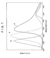
- FIG. 7 shows an example of spectral characteristics of RGB (red, green, and blue) primary color filters.
- FIG. 8 shows an example of spectral characteristics of CMY (cyan, magenta, and yellow) complementary color filters.
- an axis of ordinates indicates sensitivity, and an axis of abscissas indicates wavelength (nm).
- a B filter of the RGB primary color filters transmits a component of wavelengths from about 350 nm to about 550 nm, and transmits a component of wavelengths in the vicinity of 450 nm most.
- a G filter transmits a component of wavelengths from about 450 nm to about 650 nm, and transmits a component of wavelengths in the vicinity of 550 nm most.
- An R filter transmits a component of wavelengths from about 550 nm to about 1000 nm, and transmits a component of wavelengths in the vicinity of 650 nm most.
- a C filter of the CMY complementary color filters transmits a component of wavelengths from about 350 nm to about 650 nm, and transmits a component of wavelengths in the vicinity of 500 nm most, and also transmits a component of wavelengths from about 700 nm to about 1000 nm, and transmits a component of wavelengths in the vicinity of 750 nm most.
- An M filter transmits a component of wavelengths from about 350 nm to about 550 nm, and transmits a component of wavelengths in the vicinity of 400 nm most, and also transmits a component of wavelengths from about 550 nm to about 1000 nm, and transmits a component of wavelengths in the vicinity of 650 nm most.
- a Y filter transmits a component of wavelengths from about 450 nm to about 1000 nm, and transmits a component of wavelengths in the vicinity of 600 nm most.
- a G filter transmits a component of wavelengths from about 450 nm to about 650 nm, and transmits a component of wavelengths in the vicinity of 500 nm most, and also transmits a component of wavelengths from about 700 nm to about 1000 nm, and transmits a component of wavelengths in the vicinity of 750 nm most.
- the R filter of the RGB primary color filters (FIG. 7) transmits most of an infrared component in a range of 700 nm and more.
- the Y filter and the M filter of the CMY complementary color filters (FIG. 8) transmit the infrared component, and also the C filter starts transmitting the infrared component gradually at 700 nm.
- the CMY complementary color filters are used as the color separating filters of the image pickup element 54 to obtain a more natural color balance than the RGB primary color filters.
- the infrared cut filter 21 is positioned at one of the optical axis position A and the external position B off the optical axis in response to an operation of the operating handle 6 (FIG. 3).
- a switch 52 is connected to the infrared cut filter 21, and the switch 52 is turned on in a state in which the infrared cut filter 21 is at the external position B.
- the switch 52 is connected in parallel with a resistance 53 to which a predetermined voltage is applied.
- the image pickup element 54 generally has sensitivity to not only visible light (400 to 700 nm) but also infrared light (700 to 1000 nm).
- the infrared cut filter 21 is disposed at the optical axis position A, whereby an optical image of only a visible light component excluding an infrared light component is formed on the image pickup element 54.
- the infrared cut filter 21 is disposed at the external position B, whereby an optical image including a visible light component and an infrared light component is formed on the image pickup element 54.
- the S/H & AGC circuit 55 samples and holds the image pickup signal inputted thereto, performs automatic gain control, and then outputs the result as a video signal to an RGB separation circuit 56.
- the RGB separation circuit 56 separates the video signal inputted thereto into an R component, a G component, and a B component.
- the RGB separation circuit 56 outputs the R component, the G component, and the B component to an OPD (OPtical Detector) circuit 57, and also outputs the R component, the G component, and the B component to a white balance amplifier circuit 59.
- OPD OPD
- the OPD circuit 57 is a so-called detector circuit.
- the OPD circuit 57 detects color information within a screen from video signals (hereinafter referred to as video signals R, G, and B) of the R component, the G component, and the B component inputted from the RGB separation circuit 56, and then supplies a result of the detection to a microcomputer 58.
- the microcomputer 58 detects whether the infrared cut filter 21 is disposed at the optical axis position A or at the external position B by detecting the on/off state of the switch 52 on the basis of a current inputted via the resistance 53.
- the microcomputer 58 calculates respective integral values of the video signals R, G, and B on the basis of the result of the detection (the color information within the screen) supplied from the OPD circuit 57. Further, on the basis of a result of the calculation, the microcomputer 58 calculates a ratio (R/G) of the integral value of the video signal R to the integral value of the video signal G, and calculates a ratio (B/G) of the integral value of the video signal B to the integral value of the video signal G.
- the microcomputer 58 retains in advance blackbody curve data LA (FIG. 9) obtained by taking only visible light into consideration as a microcomputer table.
- the microcomputer 58 then calculates respective optimum gains for the video signals R, G, and B so that the calculated integral value ratios (R/G and B/G) become the same as an RGB ratio of the blackbody curve data LA.
- the microcomputer 58 supplies a result of the calculation as a control signal to the white balance amplifier circuit 59.
- the microcomputer 58 calculates respective integral values of the video signals R, G, and B on the basis of the result of the detection (the color information within the screen) supplied from the OPD circuit 57. Further, the microcomputer 58 calculates integral value ratios (R/G and B/G). The microcomputer 58 then calculates respective optimum gains for the video signals R, G, and B so that the calculated integral value ratios (R/G and B/G) become one. The microcomputer 58 supplies a result of the calculation as a control signal to the white balance amplifier circuit 59. Alternatively, the microcomputer 58 retains in advance blackbody curve data LB (FIG.
- the microcomputer 58 then calculates respective optimum gains for the video signals R, G, and B so that the calculated integral value ratios (R/G and B/G) become the same as an RGB ratio of the blackbody curve data LB obtained by taking the infrared component into consideration.
- the microcomputer 58 supplies a result of the calculation as a control signal to the white balance amplifier circuit 59.
- FIG. 9 shows examples of the blackbody curve data LA and the blackbody curve data LB obtained by taking the infrared component into consideration as the microcomputer table retained by the microcomputer 58.
- an axis of ordinates indicates the ratio (B/G) between the integral values of the B component and the G component
- an axis of abscissas indicates the ratio (R/G) between the integral values of the R component and the G component.
- the blackbody curve data LA of a visible light component indicates ratios between primary color signals R, G, and B based on a white subject taken under a light source at various color temperatures, and represents a curve such that as one of the ratios is increased, the other ratio is decreased.
- the blackbody curve data LB obtained by taking the infrared component into consideration indicates ratios between primary color signals R, G, and B based on a white subject taken under a light source at various color temperatures, with the infrared component additionally taken into consideration, and represents a curve such that as one of the ratios is increased, the other ratio is decreased. Also, the blackbody curve data LA and LB indicates that the color temperature rises as the B/G ratio is increased, and that the color temperature falls as the R/G ratio is increased. In the example of FIG. 9, integral value ratios when the color temperature is 7500 K, 5800 K, and 3200 K, respectively, are plotted.
- the white balance amplifier circuit 59 performs white balance control by controlling respective gains for the video signals R, G, and B on the basis of the control signal supplied from the microcomputer 58. Specifically, at a time of normal picture taking, the white balance amplifier circuit 59 performs blackbody curve control so that the ratio between the integral values of the three primary color signals R, G, and B becomes the same as the RGB ratio of the blackbody curve data LA (FIG. 9). At a time of night-shot picture taking, the white balance amplifier circuit 59 performs blackbody curve control so that the ratio between the integral values of the three primary color signals R, G, and B becomes the same as the RGB ratio of the blackbody curve data LB (FIG. 9) obtained by taking the infrared component into consideration, or performs gray world control so that the ratio between the integral values of the three primary color signals R, G, and B becomes one.
- a terminal 60 outputs a video signal whose white balance is controlled (that is, whose color balance is adjusted) by the white balance amplifier circuit 59.
- a white balance control process will next be described with reference to a flowchart of FIG. 10.
- the microcomputer 58 retains in advance the blackbody curve data LA and LB (FIG. 9) as microcomputer tables corresponding to picture taking conditions.
- step S11 the microcomputer 58 determines whether the infrared cut filter 21 is disposed at the optical axis position A, that is, whether the switch 52 is off on the basis of the current inputted via the resistance 53.
- the process proceeds to step S12 to read the normal blackbody curve data LA (FIG. 9).
- the microcomputer 58 calculates respective integral values of video signals R, G, and B on the basis of a detection result (color information within a screen) supplied from the OPD circuit 57.
- the microcomputer 58 calculates a ratio (R/G) of the integral value of the video signal R to the integral value of the video signal G, and calculates a ratio (B/G) of the integral value of the video signal B to the integral value of the video signal G.
- the microcomputer 58 then calculates respective optimum gains for the video signals R, G, and B so that the calculated integral value ratios (R/G and B/G) become the same as the RGB ratio of the blackbody curve data LA (FIG. 9).
- the microcomputer 58 supplies a result of the calculation as a control signal to the white balance amplifier circuit 59.
- step S13 under control of the microcomputer 58, the white balance amplifier circuit 59 performs blackbody curve control on the video signals R, G, and B so as to attain the optimum gains calculated on the basis of the blackbody curve data LA read by the process of step S12.
- step S11 When the microcomputer 58 determines in step S11 that the infrared cut filter 21 is not disposed at the optical axis position A, that is, that the infrared cut filter 21 is disposed at the external position B, the process proceeds to step S14, where the microcomputer 58 reads the blackbody curve data LB (FIG. 9) obtained by taking the infrared component into consideration. Then, the microcomputer 58 calculates respective integral values of video signals R, G, and B on the basis of a detection result (color information within a screen) supplied from the OPD circuit 57. Further, the microcomputer 58 calculates integral value ratios (R/G and B/G).
- the microcomputer 58 then calculates respective optimum gains for the video signals R, G, and B so that the calculated integral value ratios (R/G and B/G) become the same as the RGB ratio of the blackbody curve data LB (FIG. 9).
- the microcomputer 58 supplies a result of the calculation as a control signal to the white balance amplifier circuit 59.
- step S15 under control of the microcomputer 58, the white balance amplifier circuit 59 performs blackbody curve control on the video signals R, G, and B so as to attain the optimum gains calculated on the basis of the blackbody curve data LB read by the process of step S14.
- the blackbody curve data LA is read and the blackbody curve control is performed.
- the blackbody curve data LB obtained by taking the infrared component into consideration is read and the blackbody curve control is performed. Thereby optimum white balance control is performed according to picture taking conditions.
- the light source is on the blackbody curve data LA or LB, in particular, it is possible to adjust the color balance with high accuracy.
- the microcomputer 58 retains in advance the blackbody curve data LA (FIG. 9) as a microcomputer table at a time of normal picture taking.
- a process of steps S21 to S23 is the same as the above-described process of steps S11 to S13 in FIG. 10, and therefore description thereof will be omitted.
- the microcomputer 58 determines that the infrared cut filter 21 is disposed at the optical axis position A, the normal blackbody curve data LA (FIG. 9) is read, optimum gains are calculated such that ratios (R/G and B/G) between integral values of video signals R, G, and B become the same as the RGB ratio of the blackbody curve data LA, and blackbody curve control on the video signals R, G, and B is performed on the basis of a result of the calculation.
- step S21 When the microcomputer 58 determines in step S21 that the infrared cut filter 21 is not disposed at the optical axis position A, that is, that the infrared cut filter 21 is disposed at the external position B, the process proceeds to step S24, where the microcomputer 58 calculates respective integral values of video signals R, G, and B on the basis of a detection result (color information within a screen) supplied from the OPD circuit 57. Further, the microcomputer 58 calculates integral value ratios (R/G and B/G). In step S25, the microcomputer 58 then calculates respective optimum gains for the video signals R, G, and B so that the integral value ratios (R/G and B/G) calculated by the process of step S24 become one.
- the microcomputer 58 supplies a result of the calculation as a control signal to the white balance amplifier circuit 59.
- the white balance amplifier circuit 59 performs gray world control so that the integral value ratios of the video signals R, G, and B become one.
- the infrared cut filter 21 when the infrared cut filter 21 is disposed at the optical axis position A (at a time of normal picture taking), the blackbody curve data LA is read and the blackbody curve control is performed.
- the gray world control is effected so that the ratio between the video signals R, G, and B becomes one. Thereby optimum white balance control is performed according to picture taking conditions. This process is suitable especially when a color deviation is small.
- this process does not require the microcomputer 58 to retain the two kinds of blackbody curve data LA and LB in advance.
- the microcomputer 58 retains in advance the blackbody curve data LA (FIG. 9) as a microcomputer table at a time of normal picture taking.
- a process of steps S31 to S33 is the same as the above-described process of steps S11 to S13 in FIG. 10, and therefore description thereof will be omitted.
- the microcomputer 58 determines that the infrared cut filter 21 is disposed at the optical axis position A, the normal blackbody curve data LA (FIG. 9) is read, optimum gains are calculated such that ratios (R/G and B/G) between integral values of video signals R, G, and B become the same as the RGB ratio of the blackbody curve data LA, and blackbody curve control on the video signals R, G, and B is performed on the basis of a result of the calculation.
- step S31 When the microcomputer 58 determines in step S31 that the infrared cut filter 21 is not disposed at the optical axis position A, that is, that the infrared cut filter 21 is disposed at the external position B, the process proceeds to step S34, where the microcomputer 58 calculates respective integral values of video signals R, G, and B of a region of high luminance levels higher than a predetermined level on the basis of a detection result (color information within a screen) supplied from the OPD circuit 57. Further, the microcomputer 58 calculates integral value ratios (R/G and B/G).
- the region of high luminance levels higher than the predetermined level refers to luminance levels of a high luminance part whose frequency distribution accounts for 5% in a frequency distribution of luminance of the entire screen, for examples.
- This high luminance level region can be set or changed arbitrarily.
- step S35 the microcomputer 58 then calculates respective optimum gains for the video signals R, G, and B so that the integral value ratios (R/G and B/G) calculated by the process of step S34 become one.
- the microcomputer 58 supplies a result of the calculation as a control signal to the white balance amplifier circuit 59.
- the white balance amplifier circuit 59 performs gray world control so that the integral value ratios of the video signals R, G, and B become one.
- the blackbody curve data LA is read and the blackbody curve control is performed.
- the gray world control is effected so that the ratio between the integral values of the video signals R, G, and B of the high luminance level region becomes one. Thereby optimum white balance control is performed according to picture taking conditions. This process results in a smaller shift in color balance even when there is a color deviation, as compared with the above-described process of FIG. 11.
- the microcomputer 58 retains in advance the blackbody curve data LA (FIG. 9) as a microcomputer table at a time of normal picture taking.
- a process of steps S41 to S43 is the same as the above-described process of steps S11 to S13 in FIG. 10, and therefore description thereof will be omitted.
- the microcomputer 58 determines that the infrared cut filter 21 is disposed at the optical axis position A, the normal blackbody curve data LA (FIG. 9) is read, optimum gains are calculated such that ratios (R/G and B/G) between integral values of video signals R, G, and B become the same as the RGB ratio of the blackbody curve data LA, and blackbody curve control on the video signals R, G, and B is performed on the basis of a result of the calculation.
- step S41 determines in step S41 that the infrared cut filter 21 is not disposed at the optical axis position A, that is, that the infrared cut filter 21 is disposed at the external position B
- the microcomputer 58 determines that it is a time of night-shot picture taking, and the process proceeds to step S44, where the microcomputer 58 calculates respective integral values of video signals R, G, and B of a region of medium luminance levels higher than a predetermined level and lower than a saturation luminance level on the basis of a detection result (color information within a screen) supplied from the OPD circuit 57. Further, the microcomputer 58 calculates integral value ratios (R/G and B/G).
- the region of medium luminance levels higher than the predetermined level and lower than the saturation luminance level refers to luminance levels excluding luminance levels of a high luminance part whose frequency distribution accounts for 5% in a frequency distribution of luminance of the entire screen and luminance levels of a low luminance part whose frequency distribution accounts for 20% in the frequency distribution of luminance of the entire screen, for example.
- This medium luminance level region can be set or changed arbitrarily.
- step S45 the microcomputer 58 then calculates respective optimum gains for the video signals R, G, and B so that the integral value ratios (R/G and B/G) calculated by the process of step S44 become one.
- the microcomputer 58 supplies a result of the calculation as a control signal to the white balance amplifier circuit 59.
- the white balance amplifier circuit 59 performs gray world control so that the integral value ratios of the video signals R, G, and B become one.
- the blackbody curve data LA is read and the blackbody curve control is performed.
- the gray world control is effected so that the ratio between the integral values of the video signals R, G, and B of the medium luminance level region becomes one. Thereby optimum white balance control is performed according to picture taking conditions. This process results in a smaller shift in color balance even when there are many saturation luminance levels, as compared with the above-described process of FIG. 12.
- the microcomputer 58 detects presence or absence of the infrared cut filter 21 on the basis of an on state or an off state of the switch 52.
- the infrared cut filter 21 is disposed at the optical axis position A (at a time of normal picture taking)
- the normal blackbody curve control is performed.
- the blackbody curve control taking the infrared component into consideration is performed, or the gray world control is performed according to luminance levels. In other words, a method of controlling a white balance is changed according to whether the infrared cut filter 21 is present or not. It is thereby possible to realize natural color reproduction of the camera even when an infrared component is present.
- Embodiments of the present invention can be effectively applied particularly to subjects in night views, at twilight, and under a dim fluorescent light, heavenly bodies and the like to thereby realize natural color reproduction of the camera and improve sensitivity.
- the white balance control method is changed according to whether the infrared cut filter 21 is present or not
- embodiments of the present invention are not necessarily limited to this.
- the white balance control method can be changed according to whether the filter is present or not.
- the microcomputer 58 can realize natural color reproduction of the camera without retaining new blackbody curve data adjusted to the filter with an infrared component taken into consideration.
- embodiments of the present invention do not perform achromatization (produces color output) at a time of low illuminance because of increased sensitivity and non-noticeable color noise at a time of low illuminance. Embodiments of the present invention thus makes it possible to realize more natural color reproduction.
- the series of processes described above can be carried out not only by hardware but also by software.
- a program comprising the software is installed from a network or a recording medium onto a computer incorporated in special hardware, or onto for example a general-purpose personal computer that can perform various functions by installing various programs thereon.
- FIG. 14 is a diagram showing an example of internal configuration of a general-purpose personal computer 100.
- a CPU (Central Processing Unit) 101 performs various processing according to a program stored in a ROM (Read Only Memory) 102 or a program loaded into a RAM (Random Access Memory) 103 from a storage unit 108.
- the RAM 103 also stores data and the like necessary for the CPU 101 to perform the various processing, as required.
- the CPU 101, the ROM 102, and the RAM 103 are connected to each other via a bus 104.
- the bus 104 is also connected with an input-output interface 105.
- the input-output interface 105 is connected with an input unit 106 comprising a keyboard, a mouse and the like, an output unit 107 comprising a display and the like, a storage unit 108, and a communication unit 109.
- the communication unit 109 performs communication processing via a network.
- the input-output interface 105 is also connected with a drive 110, into which a removable medium 111 such as a magnetic disk, an optical disk, a magneto-optical disk, a semiconductor memory or the like is inserted as required.
- a removable medium 111 such as a magnetic disk, an optical disk, a magneto-optical disk, a semiconductor memory or the like is inserted as required.
- a computer program read from the removable medium 111 is installed in the storage unit 108 as required.
- the recording medium on which the program to be installed onto the computer and set in a state of being executable by the computer is recorded is not only formed by the removable medium 111 distributed to users to provide the program separately from the apparatus proper, the removable medium 111 comprising a magnetic disk (including flexible disks), an optical disk (including CD-ROM (Compact Disk-Read Only Memory) and DVD (Digital Versatile Disk)), a magneto-optical disk (including MD (Mini-Disk) (trademark)), a semiconductor memory or the like which has the program recorded thereon, but also formed by the ROM 103, a hard disk included in the storage unit 108, or the like which has the program recorded thereon and is provided to the user in a state of being preincorporated in the apparatus proper.
- the removable medium 111 comprising a magnetic disk (including flexible disks), an optical disk (including CD-ROM (Compact Disk-Read Only Memory) and DVD (Digital Versatile Disk)), a magneto-optical disk (including MD (Mini-Disk)
- the steps describing the program stored on the recording medium include not only processing carried out in time series in the included order but also processing carried out in parallel or individually and not necessarily in time series.
Landscapes
- Engineering & Computer Science (AREA)
- Multimedia (AREA)
- Signal Processing (AREA)
- Color Television Image Signal Generators (AREA)
- Processing Of Color Television Signals (AREA)
Applications Claiming Priority (2)
| Application Number | Priority Date | Filing Date | Title |
|---|---|---|---|
| JP2003365462 | 2003-10-27 | ||
| JP2003365462A JP4210922B2 (ja) | 2003-10-27 | 2003-10-27 | 撮像装置および方法 |
Publications (2)
| Publication Number | Publication Date |
|---|---|
| EP1528816A2 true EP1528816A2 (de) | 2005-05-04 |
| EP1528816A3 EP1528816A3 (de) | 2007-03-28 |
Family
ID=34420090
Family Applications (1)
| Application Number | Title | Priority Date | Filing Date |
|---|---|---|---|
| EP04256429A Withdrawn EP1528816A3 (de) | 2003-10-27 | 2004-10-19 | BILDERFASSUNGSfCEINRICHTUNG UND VERFAHREN |
Country Status (5)
| Country | Link |
|---|---|
| US (1) | US7746386B2 (de) |
| EP (1) | EP1528816A3 (de) |
| JP (1) | JP4210922B2 (de) |
| KR (1) | KR101035788B1 (de) |
| CN (1) | CN1612616B (de) |
Cited By (1)
| Publication number | Priority date | Publication date | Assignee | Title |
|---|---|---|---|---|
| EP2785046B1 (de) * | 2013-03-28 | 2018-09-12 | Fujitsu Limited | Bildkorrekturvorrichtung, Bildkorrekturverfahren und biometrische Authentifizierungsvorrichtung |
Families Citing this family (35)
| Publication number | Priority date | Publication date | Assignee | Title |
|---|---|---|---|---|
| JP2007074299A (ja) | 2005-09-06 | 2007-03-22 | Sony Corp | 画像処理方法、画像処理プログラムおよび画像処理装置、ならびに、撮像装置、撮像方法および撮像プログラム |
| CN100484203C (zh) * | 2006-04-19 | 2009-04-29 | 中国科学院自动化研究所 | 同视场多光谱视频流的获取装置和方法 |
| JP2008131292A (ja) * | 2006-11-20 | 2008-06-05 | Olympus Corp | 撮像装置 |
| US8049789B2 (en) * | 2006-12-15 | 2011-11-01 | ON Semiconductor Trading, Ltd | White balance correction using illuminant estimation |
| JP4720771B2 (ja) * | 2007-04-03 | 2011-07-13 | ソニー株式会社 | 撮像装置及び撮像方法 |
| JP5349790B2 (ja) * | 2007-11-16 | 2013-11-20 | キヤノン株式会社 | 画像処理装置、画像処理方法、及びプログラム |
| JP4813517B2 (ja) * | 2008-05-29 | 2011-11-09 | オリンパス株式会社 | 画像処理装置、画像処理プログラム、画像処理方法、および電子機器 |
| EP2395499A1 (de) * | 2008-07-23 | 2011-12-14 | Qualcomm Mems Technologies, Inc | Kalibrierung von Pixelelementen durch Ermittlung der Leuchtdichte von Weisslicht und Kompensation von Verschiebungen im Farbspektrum |
| KR101531709B1 (ko) * | 2008-10-17 | 2015-07-06 | 삼성전자 주식회사 | 고감도 컬러 영상을 제공하기 위한 영상 처리 장치 및 방법 |
| JP4821847B2 (ja) * | 2008-12-26 | 2011-11-24 | ソニー株式会社 | 光学部品の切換機構、レンズ鏡筒及び撮像装置 |
| JP5432075B2 (ja) * | 2010-07-06 | 2014-03-05 | パナソニック株式会社 | 撮像装置および色温度算出方法 |
| JP5539079B2 (ja) * | 2010-07-15 | 2014-07-02 | キヤノン株式会社 | 撮像装置、その制御方法及びプログラム |
| TW201208350A (en) * | 2010-08-06 | 2012-02-16 | Hon Hai Prec Ind Co Ltd | Image sensing board inspecting device, system and method |
| US9071740B1 (en) | 2011-10-28 | 2015-06-30 | Google Inc. | Modular camera system |
| US9197686B1 (en) | 2012-01-06 | 2015-11-24 | Google Inc. | Backfill of video stream |
| JP2016012746A (ja) | 2012-11-07 | 2016-01-21 | ソニー株式会社 | 信号処理装置、信号処理方法及び信号処理プログラム |
| CN104113743B (zh) * | 2013-04-18 | 2017-09-15 | 深圳中兴力维技术有限公司 | 低照度下彩色摄像机自动白平衡处理方法及装置 |
| CN104113744B (zh) * | 2013-04-18 | 2018-01-19 | 深圳中兴力维技术有限公司 | 全天候彩色摄像机白平衡处理方法及装置 |
| US9521385B2 (en) | 2014-03-27 | 2016-12-13 | Himax Imaging Limited | Image sensor equipped with additional group of selectively transmissive filters for illuminant estimation, and associated illuminant estimation method |
| EP3149936B1 (de) * | 2014-05-29 | 2020-04-01 | Nokia Technologies Oy | Vorrichtung und verfahren zur bildverarbeitung |
| JP6508890B2 (ja) * | 2014-07-07 | 2019-05-08 | キヤノン株式会社 | 画像処理装置、その制御方法、および制御プログラム |
| WO2016093070A1 (ja) | 2014-12-10 | 2016-06-16 | ソニー株式会社 | 撮像装置、撮像方法、およびプログラム、並びに画像処理装置 |
| JP2016213628A (ja) | 2015-05-07 | 2016-12-15 | ソニー株式会社 | 撮像装置、撮像方法、およびプログラム、並びに画像処理装置 |
| US9544485B2 (en) | 2015-05-27 | 2017-01-10 | Google Inc. | Multi-mode LED illumination system |
| US9386230B1 (en) * | 2015-06-12 | 2016-07-05 | Google Inc. | Day and night detection based on one or more of illuminant detection, lux level detection, and tiling |
| US9554063B2 (en) | 2015-06-12 | 2017-01-24 | Google Inc. | Using infrared images of a monitored scene to identify windows |
| US9454820B1 (en) | 2015-06-12 | 2016-09-27 | Google Inc. | Using a scene illuminating infrared emitter array in a video monitoring camera for depth determination |
| JP6650691B2 (ja) * | 2015-07-02 | 2020-02-19 | キヤノン株式会社 | 撮像装置 |
| US10180615B2 (en) | 2016-10-31 | 2019-01-15 | Google Llc | Electrochromic filtering in a camera |
| CN106709887A (zh) * | 2017-01-06 | 2017-05-24 | 凌云光技术集团有限责任公司 | 基于色温曲线的图像的灰度世界白平衡调整方法及装置 |
| JP6443867B1 (ja) * | 2017-06-15 | 2018-12-26 | キヤノン株式会社 | 発光装置、表示装置、及び、制御方法 |
| JP7614893B2 (ja) * | 2021-03-15 | 2025-01-16 | キヤノン株式会社 | 画像処理装置、画像処理方法、及びプログラム |
| JP7790899B2 (ja) | 2021-09-09 | 2025-12-23 | キヤノン株式会社 | 画像処理装置、画像処理方法、及びプログラム |
| US12256157B2 (en) | 2021-09-09 | 2025-03-18 | Canon Kabushiki Kaisha | Image processing apparatus, image processing method, and storage medium |
| JP2023161376A (ja) | 2022-04-25 | 2023-11-07 | キヤノン株式会社 | 画像処理装置、画像処理方法、及びプログラム |
Family Cites Families (48)
| Publication number | Priority date | Publication date | Assignee | Title |
|---|---|---|---|---|
| JPH0286385A (ja) | 1988-09-22 | 1990-03-27 | Sony Corp | カラーモード・赤外モード共用ビデオカメラ |
| JP2751297B2 (ja) | 1989-01-24 | 1998-05-18 | ソニー株式会社 | オートホワイトバランス回路 |
| US5282022A (en) | 1989-11-17 | 1994-01-25 | Sanyo Electric Co., Ltd. | White balance adjusting apparatus for automatically adjusting white balance in response to luminance information signal and color information signal obtained from image sensing device |
| US5235428A (en) * | 1990-02-21 | 1993-08-10 | Sony Corporation | Auto-focus system for video camera |
| US5155585A (en) * | 1990-08-13 | 1992-10-13 | Brother Kogyo Kabushiki Kaisha | Image pickup apparatus for receiving light and converting to an electrical signal corresponding to the light |
| JPH0568257A (ja) | 1991-07-15 | 1993-03-19 | Canon Inc | カラー撮像装置 |
| US5648818A (en) * | 1992-10-09 | 1997-07-15 | Canon Kabushiki Kaisha | Image pickup apparatus having color separation matrix |
| JPH06133191A (ja) * | 1992-10-16 | 1994-05-13 | Canon Inc | 撮像装置 |
| JPH0779444A (ja) * | 1993-09-06 | 1995-03-20 | Asahi Optical Co Ltd | スチルビデオカメラ |
| US6421083B1 (en) * | 1996-03-29 | 2002-07-16 | Sony Corporation | Color imaging device and method |
| US5978379A (en) * | 1997-01-23 | 1999-11-02 | Gadzoox Networks, Inc. | Fiber channel learning bridge, learning half bridge, and protocol |
| JPH1188896A (ja) * | 1997-09-03 | 1999-03-30 | Canon Inc | 撮像装置 |
| JP3867367B2 (ja) | 1997-09-26 | 2007-01-10 | ソニー株式会社 | ホワイトバランス制御機能を備えたビデオ撮影装置 |
| WO1999043002A2 (en) * | 1998-02-24 | 1999-08-26 | Seagate Technology Llc | Preserving loop fairness with dynamic half-duplex |
| JPH11341502A (ja) | 1998-05-27 | 1999-12-10 | Sony Corp | 固体撮像素子の信号処理回路およびカメラシステム |
| US6421711B1 (en) * | 1998-06-29 | 2002-07-16 | Emc Corporation | Virtual ports for data transferring of a data storage system |
| US6401128B1 (en) * | 1998-08-07 | 2002-06-04 | Brocade Communiations Systems, Inc. | System and method for sending and receiving frames between a public device and a private device |
| JP2000059798A (ja) | 1998-08-10 | 2000-02-25 | Sony Corp | 近赤外光/可視光共用撮像装置 |
| US6717910B1 (en) * | 1998-09-30 | 2004-04-06 | Stmicroelectronics, Inc. | Method and apparatus for controlling network data congestion |
| JP2000152072A (ja) * | 1998-11-11 | 2000-05-30 | Minolta Co Ltd | デジタルカメラ |
| JP3849834B2 (ja) * | 1999-02-02 | 2006-11-22 | 富士写真フイルム株式会社 | オートホワイトバランス制御方法 |
| GB2350032B (en) * | 1999-05-12 | 2001-04-11 | 3Com Corp | Method and apparatus for configuration of stackable units in packet-based communication systems |
| US6930723B1 (en) * | 1999-07-13 | 2005-08-16 | Canon Kabushiki Kaisha | Quantity-of-light adjusting apparatus |
| JP2001216206A (ja) * | 2000-02-01 | 2001-08-10 | Nec Corp | ループ状インターフェースの障害解析方法及び障害解析機能を有するシステム |
| DE60131079T2 (de) * | 2000-06-05 | 2008-08-07 | Qlogic Switch Products, Inc., Aliso Viejo | Hardware-erzwungene loop-level hard zoning für faserkanalschalteranordnung |
| JP3892648B2 (ja) * | 2000-06-30 | 2007-03-14 | 株式会社リコー | 画像入力装置、ホワイトバランス調整方法、およびその方法を実行するためのプログラムを格納したコンピュータが読取可能な記録媒体 |
| JP4003399B2 (ja) * | 2000-10-23 | 2007-11-07 | ソニー株式会社 | 画像処理装置および方法、並びに記録媒体 |
| US6744772B1 (en) * | 2000-11-30 | 2004-06-01 | Western Digital Ventures, Inc. | Converting asynchronous packets into isochronous packets for transmission through a multi-dimensional switched fabric network |
| JP2002218481A (ja) | 2001-01-12 | 2002-08-02 | Olympus Optical Co Ltd | 撮像装置 |
| US6968463B2 (en) * | 2001-01-17 | 2005-11-22 | Hewlett-Packard Development Company, L.P. | System for controlling access to resources in a storage area network |
| JP2002232906A (ja) * | 2001-01-31 | 2002-08-16 | Ricoh Co Ltd | ホワイトバランス制御装置 |
| US6834311B2 (en) * | 2001-04-04 | 2004-12-21 | Sun Microsystems, Inc. | Method, system, and program for enabling communication between devices using dynamic addressing |
| US7110394B1 (en) * | 2001-06-25 | 2006-09-19 | Sanera Systems, Inc. | Packet switching apparatus including cascade ports and method for switching packets |
| GB0119070D0 (en) * | 2001-08-06 | 2001-09-26 | Ibm | Method and apparatus for managing a loop network |
| US7265781B2 (en) * | 2001-08-22 | 2007-09-04 | Fujifilm Corporation | Method and apparatus for determining a color correction matrix by minimizing a color difference maximum or average value |
| JP2003070009A (ja) | 2001-08-28 | 2003-03-07 | Sharp Corp | 撮像装置 |
| US20030084219A1 (en) * | 2001-10-26 | 2003-05-01 | Maxxan Systems, Inc. | System, apparatus and method for address forwarding for a computer network |
| JP2003141055A (ja) * | 2001-11-07 | 2003-05-16 | Hitachi Ltd | 計算機システムの接続設定方法 |
| US7206287B2 (en) * | 2001-12-26 | 2007-04-17 | Alcatel Canada Inc. | Method and system for isolation of a fault location in a communications device |
| US7047326B1 (en) * | 2002-01-31 | 2006-05-16 | Harman International Industries, Inc. | Use of a remote control with a device having a built-in communication port |
| US7310389B2 (en) * | 2002-03-14 | 2007-12-18 | Syntle Sys Research, Inc | Method and apparatus for determining the errors of a multi-valued data signal that are outside the limits of an eye mask |
| US7787387B2 (en) * | 2002-03-21 | 2010-08-31 | Broadcom Corporation | Auto-selection of SGMII or SerDes pass-through modes |
| US7194538B1 (en) * | 2002-06-04 | 2007-03-20 | Veritas Operating Corporation | Storage area network (SAN) management system for discovering SAN components using a SAN management server |
| US7664018B2 (en) * | 2002-07-02 | 2010-02-16 | Emulex Design & Manufacturing Corporation | Methods and apparatus for switching fibre channel arbitrated loop devices |
| US7533256B2 (en) * | 2002-10-31 | 2009-05-12 | Brocade Communications Systems, Inc. | Method and apparatus for encryption of data on storage units using devices inside a storage area network fabric |
| US20040100944A1 (en) * | 2002-11-27 | 2004-05-27 | Scott Richmond | Serial ATA frame structure routing circuitry and protocols |
| US7289434B2 (en) * | 2002-12-05 | 2007-10-30 | Cisco Technology, Inc. | Method for verifying function of redundant standby packet forwarder |
| US7221650B1 (en) * | 2002-12-23 | 2007-05-22 | Intel Corporation | System and method for checking data accumulators for consistency |
-
2003
- 2003-10-27 JP JP2003365462A patent/JP4210922B2/ja not_active Expired - Fee Related
-
2004
- 2004-10-01 US US10/954,308 patent/US7746386B2/en active Active
- 2004-10-19 EP EP04256429A patent/EP1528816A3/de not_active Withdrawn
- 2004-10-26 KR KR1020040085540A patent/KR101035788B1/ko not_active Expired - Fee Related
- 2004-10-26 CN CN2004100810005A patent/CN1612616B/zh not_active Expired - Fee Related
Cited By (1)
| Publication number | Priority date | Publication date | Assignee | Title |
|---|---|---|---|---|
| EP2785046B1 (de) * | 2013-03-28 | 2018-09-12 | Fujitsu Limited | Bildkorrekturvorrichtung, Bildkorrekturverfahren und biometrische Authentifizierungsvorrichtung |
Also Published As
| Publication number | Publication date |
|---|---|
| JP4210922B2 (ja) | 2009-01-21 |
| US7746386B2 (en) | 2010-06-29 |
| CN1612616B (zh) | 2011-03-16 |
| JP2005130317A (ja) | 2005-05-19 |
| CN1612616A (zh) | 2005-05-04 |
| EP1528816A3 (de) | 2007-03-28 |
| KR20050040733A (ko) | 2005-05-03 |
| US20050088537A1 (en) | 2005-04-28 |
| KR101035788B1 (ko) | 2011-05-20 |
Similar Documents
| Publication | Publication Date | Title |
|---|---|---|
| US7746386B2 (en) | Image pickup device and method | |
| EP1725051B1 (de) | Weissabgleichssteuerung für eine Bildaufnahmevorrichtung | |
| US5319449A (en) | White balance control device and video camera with a white balance control device | |
| KR920003652B1 (ko) | 촬상장치 | |
| US8692903B2 (en) | Imaging device, imaging method and computer readable recording medium storing program for performing the imaging method | |
| US7437065B2 (en) | Imaging apparatus | |
| JPH01269389A (ja) | カメラの白バランス調整装置 | |
| JP2004120202A (ja) | 撮像装置,撮像モード切替方法 | |
| JP2012119788A (ja) | 撮影装置、画像処理装置、撮影方法及び画像処理方法 | |
| JP4670465B2 (ja) | ホワイトバランス制御装置 | |
| JP3142603B2 (ja) | 画像撮影装置のホワイトバランス装置 | |
| JP2009033386A (ja) | 撮影装置及び撮影方法 | |
| JPH11341500A (ja) | カラー撮像装置およびホワイトバランス補正方法 | |
| JP4239219B2 (ja) | オートホワイトバランス調整方法及び装置 | |
| JP3535678B2 (ja) | スチルビデオカメラのホワイトバランス調整装置 | |
| JP3163065B2 (ja) | 画像撮影装置 | |
| KR100319860B1 (ko) | 캠코더의 화이트 밸런스 보정장치 | |
| KR19990020315A (ko) | 조리개 자동제어방법 | |
| JP2005303837A (ja) | 電子カメラ | |
| JP2007020020A (ja) | 映像信号処理装置 | |
| JPH0723411A (ja) | ビデオカメラ | |
| JPH08280033A (ja) | ホワイトバランス制御方法 | |
| JP2006186536A (ja) | 撮像装置及びホワイトバランス制御方法 | |
| KR19990048849A (ko) | 필름 카메라가 부착된 캠코더 및 그 작동 방법 | |
| JP2007036677A (ja) | 撮像装置及びその制御方法 |
Legal Events
| Date | Code | Title | Description |
|---|---|---|---|
| PUAI | Public reference made under article 153(3) epc to a published international application that has entered the european phase |
Free format text: ORIGINAL CODE: 0009012 |
|
| AK | Designated contracting states |
Kind code of ref document: A2 Designated state(s): AT BE BG CH CY CZ DE DK EE ES FI FR GB GR HU IE IT LI LU MC NL PL PT RO SE SI SK TR |
|
| AX | Request for extension of the european patent |
Extension state: AL HR LT LV MK |
|
| PUAL | Search report despatched |
Free format text: ORIGINAL CODE: 0009013 |
|
| AK | Designated contracting states |
Kind code of ref document: A3 Designated state(s): AT BE BG CH CY CZ DE DK EE ES FI FR GB GR HU IE IT LI LU MC NL PL PT RO SE SI SK TR |
|
| AX | Request for extension of the european patent |
Extension state: AL HR LT LV MK |
|
| 17P | Request for examination filed |
Effective date: 20070912 |
|
| 17Q | First examination report despatched |
Effective date: 20071029 |
|
| AKX | Designation fees paid |
Designated state(s): DE FR GB |
|
| STAA | Information on the status of an ep patent application or granted ep patent |
Free format text: STATUS: THE APPLICATION IS DEEMED TO BE WITHDRAWN |
|
| 18D | Application deemed to be withdrawn |
Effective date: 20140501 |