EP1522671A2 - Store à rouleau - Google Patents
Store à rouleau Download PDFInfo
- Publication number
- EP1522671A2 EP1522671A2 EP04024283A EP04024283A EP1522671A2 EP 1522671 A2 EP1522671 A2 EP 1522671A2 EP 04024283 A EP04024283 A EP 04024283A EP 04024283 A EP04024283 A EP 04024283A EP 1522671 A2 EP1522671 A2 EP 1522671A2
- Authority
- EP
- European Patent Office
- Prior art keywords
- winding
- winding device
- web
- webs
- surface web
- Prior art date
- Legal status (The legal status is an assumption and is not a legal conclusion. Google has not performed a legal analysis and makes no representation as to the accuracy of the status listed.)
- Granted
Links
Images
Classifications
-
- E—FIXED CONSTRUCTIONS
- E06—DOORS, WINDOWS, SHUTTERS, OR ROLLER BLINDS IN GENERAL; LADDERS
- E06B—FIXED OR MOVABLE CLOSURES FOR OPENINGS IN BUILDINGS, VEHICLES, FENCES OR LIKE ENCLOSURES IN GENERAL, e.g. DOORS, WINDOWS, BLINDS, GATES
- E06B9/00—Screening or protective devices for wall or similar openings, with or without operating or securing mechanisms; Closures of similar construction
- E06B9/24—Screens or other constructions affording protection against light, especially against sunshine; Similar screens for privacy or appearance; Slat blinds
- E06B9/40—Roller blinds
-
- E—FIXED CONSTRUCTIONS
- E06—DOORS, WINDOWS, SHUTTERS, OR ROLLER BLINDS IN GENERAL; LADDERS
- E06B—FIXED OR MOVABLE CLOSURES FOR OPENINGS IN BUILDINGS, VEHICLES, FENCES OR LIKE ENCLOSURES IN GENERAL, e.g. DOORS, WINDOWS, BLINDS, GATES
- E06B9/00—Screening or protective devices for wall or similar openings, with or without operating or securing mechanisms; Closures of similar construction
- E06B9/56—Operating, guiding or securing devices or arrangements for roll-type closures; Spring drums; Tape drums; Counterweighting arrangements therefor
- E06B9/64—Operating, guiding or securing devices or arrangements for roll-type closures; Spring drums; Tape drums; Counterweighting arrangements therefor with lowerable roller
-
- E—FIXED CONSTRUCTIONS
- E06—DOORS, WINDOWS, SHUTTERS, OR ROLLER BLINDS IN GENERAL; LADDERS
- E06B—FIXED OR MOVABLE CLOSURES FOR OPENINGS IN BUILDINGS, VEHICLES, FENCES OR LIKE ENCLOSURES IN GENERAL, e.g. DOORS, WINDOWS, BLINDS, GATES
- E06B9/00—Screening or protective devices for wall or similar openings, with or without operating or securing mechanisms; Closures of similar construction
- E06B9/56—Operating, guiding or securing devices or arrangements for roll-type closures; Spring drums; Tape drums; Counterweighting arrangements therefor
- E06B9/66—Operating, guiding or securing devices or arrangements for roll-type closures; Spring drums; Tape drums; Counterweighting arrangements therefor with a roller situated at the bottom
-
- E—FIXED CONSTRUCTIONS
- E06—DOORS, WINDOWS, SHUTTERS, OR ROLLER BLINDS IN GENERAL; LADDERS
- E06B—FIXED OR MOVABLE CLOSURES FOR OPENINGS IN BUILDINGS, VEHICLES, FENCES OR LIKE ENCLOSURES IN GENERAL, e.g. DOORS, WINDOWS, BLINDS, GATES
- E06B9/00—Screening or protective devices for wall or similar openings, with or without operating or securing mechanisms; Closures of similar construction
- E06B9/24—Screens or other constructions affording protection against light, especially against sunshine; Similar screens for privacy or appearance; Slat blinds
- E06B2009/2423—Combinations of at least two screens
- E06B2009/2441—Screens joined one below the other
-
- E—FIXED CONSTRUCTIONS
- E06—DOORS, WINDOWS, SHUTTERS, OR ROLLER BLINDS IN GENERAL; LADDERS
- E06B—FIXED OR MOVABLE CLOSURES FOR OPENINGS IN BUILDINGS, VEHICLES, FENCES OR LIKE ENCLOSURES IN GENERAL, e.g. DOORS, WINDOWS, BLINDS, GATES
- E06B9/00—Screening or protective devices for wall or similar openings, with or without operating or securing mechanisms; Closures of similar construction
- E06B9/24—Screens or other constructions affording protection against light, especially against sunshine; Similar screens for privacy or appearance; Slat blinds
- E06B2009/2423—Combinations of at least two screens
- E06B2009/2447—Parallel screens
- E06B2009/2458—Parallel screens moving simultaneously
-
- E—FIXED CONSTRUCTIONS
- E06—DOORS, WINDOWS, SHUTTERS, OR ROLLER BLINDS IN GENERAL; LADDERS
- E06B—FIXED OR MOVABLE CLOSURES FOR OPENINGS IN BUILDINGS, VEHICLES, FENCES OR LIKE ENCLOSURES IN GENERAL, e.g. DOORS, WINDOWS, BLINDS, GATES
- E06B9/00—Screening or protective devices for wall or similar openings, with or without operating or securing mechanisms; Closures of similar construction
- E06B9/24—Screens or other constructions affording protection against light, especially against sunshine; Similar screens for privacy or appearance; Slat blinds
- E06B9/40—Roller blinds
- E06B2009/405—Two rollers
Definitions
- the present invention relates to a winding device, in particular a Winding blind with the features of the independent claim.
- Venetian blinds where a rotatable winding roll is arranged above an opening to be covered, allow only a Aufund Unrolling the fabric web on the winding roll and thus a variable opening upwards.
- Such Venetian blinds serve, for example, for shading Window openings in houses and apartments.
- Venetian blinds are used, for example, in greenhouses.
- the Fabric web can in such conventional winding devices of only be opened down to the top, which is unfavorable for some applications.
- DE 202 14 076 U1 Another system for variable ventilation and / or shading of Buildings or rooms is known from DE 202 14 076 U1.
- This device comprises an upper and a lower roll system for winding and unrolling a screen, so that different tissue types are optional on the top or bottom Wrapping roll can be rolled up.
- the room is, for example, with a Tight fabric type shaded or by means of a very marmaschig woven Fabric type made air and translucent.
- the two winding elements are each rigidly anchored above and below the room opening.
- Such a device can not extend over any width, because the differences in the Diameters of the upper and lower roll at any time by means of a Clamping device must be balanced and the storage of the upper Winding roll is problematic for very wide and thus heavy shielding.
- the use of such a device to cover a very wide Carteres thus requires a juxtaposition of several such devices.
- a similar kind of roller blind device with a first and a different provided second material web, which are each wound around a winding axis, and each with a first end in the region of its winding axis on a holder are fixed, is further known from DE 92 10 938 U1.
- the first and the second Material web are firmly connected together at their free second end and the Holders are movable relative to each other toward or away from each other, wherein in these movements, the two webs are up or unwound.
- An object of the present invention is to provide a winding device for variable covering of surfaces, for example openings in rooms or buildings, with Covering elements of different textures or cropping these surfaces which is simple to set up and operate and which is also suitable for large areas is suitable.
- the winding device with the features of independent claim allows variable coverage of areas, eg. Openings in rooms or buildings, with cover elements, where a Cover element at least two or more differently procured, includes adjacent surface webs and being associated with the arrangement of two or more winding elements, the area to be covered as required, each with at least one surface track of a constant selectable condition can remain covered.
- a Cover element at least two or more differently procured, includes adjacent surface webs and being associated with the arrangement of two or more winding elements, the area to be covered as required, each with at least one surface track of a constant selectable condition can remain covered.
- a Cover element at least two or more differently procured, includes adjacent surface webs and being associated with the arrangement of two or more winding elements, the area to be covered as required, each with at least one surface track of a constant selectable condition can remain covered.
- the present invention is different in the range of at least two surface webs Textures each arranged at least one rotatable winding element, wherein the respective surface paths each variable
- the winding device With the winding device according to the invention, it is possible to one Covering or releasing opening in a housing, a building, a Stable, a greenhouse or the like to open or close variably to shade or largely release.
- the inventive Winding device is an advantageous development, since the currently known Venetian blind devices with upper rigid attachment variable ventilation of one upper opening with simultaneous coverage of a lower area of the opening is not allow.
- winding device in addition to those already mentioned, there are numerous other applications for the winding device according to the invention.
- such winding devices be used as mobile partitions in the outer and / or interior, for example.
- variably manageable fire protection walls, Soundproof walls and / or noise barriers are realized only in the If necessary, pulled out of their upper suspension and when not in use again can be rolled.
- UV barriers for example for shielding welding workplaces.
- the winding device according to the invention can be used advantageously.
- the mentioned Use cases or parts thereof are each by means of a winding device easily realizable, since the different tissue or surface webs be adapted to the respective purposes and be rolled out accordingly can.
- surface web or “Surfaces of different textures” are used, so are with it basically includes sections of shielding elements and includes, which optionally from different types of fabric such as net mesh or conventional more or less densely woven fabrics, of strings running side by side, Ropes or flat bands, or even from closed surfaces such as.
- Plastic or synthetic fiber films or tarpaulins can exist.
- the like designed sections can each be made of natural and / or synthetic fibers or foils o.
- a preferred embodiment of the present invention extends Such a portion of a shielding over the entire width or Length of the winding device in the longitudinal direction of the winding elements and corresponds in its length or width approximately the length or width of the Covered area, so that a single such section at appropriate Winding the winding device can cover the entire area to be covered.
- a typical width of a winding device according to the invention can, for example, up to 20 Meters or more. Depending on the need, however, are also much larger Widths variably coverable.
- any number of such sections are each fixed at their longitudinal edges connected together, so that the entire shielding be arbitrarily long can.
- According to the invention is always such a large proportion of the shielding on the rolled up at least two winding elements that the length of the exposed, the Surface covering portion of the shielding member maximum of the height or width of the corresponds to the area to be covered.
- At least one winding element is arranged in each case.
- the Winding elements of the winding device according to the invention are in particular in one Arranged middle region of their respective associated surface track and at this place firmly connected to the corresponding surface track, so that at a rotation of the corresponding winding element emanating from its center two-ply winding of the respective surface web around the winding element around he follows.
- two or more winding elements within a Be arranged portion of the shielding must be in each case so be distributed over the area of the surface track that they are during the Winding process does not interfere with each other. For example. must when using two Wickelelementen per surface web the first about in the upper quarter and the second be arranged in the lower fourth of the surface web.
- a arranged in the region of the lowest arranged surface web Winding element can optionally be arranged at the lower end of the surface web be, so that at least the lowermost surface web of a lower edge can be wound single-layer starting.
- By winding the bottom one Surface track can be an exemption of the area, eg. The building or Room opening, done from below.
- it is alternatively possible with a already rolled up lower surface to roll up only the upper winding element and at the same time to fix the lower winding element in its height. Possibly. can do this lower winding element to be rotatably anchored, so that the surface to be covered not completely exposed, but only with one of several optional Surfaces can be covered.
- the Winding elements not firmly anchored in the direction of movement of the cover, but lead during the winding process in the direction of movement of the Covering directed movement, resulting from the shortening or Extension of the exposed surface of the respective surface track results.
- a hanging embodiment of the present invention moves Wrapping element during the winding up and during the Unwinding down, if not another, overlying Winding performs a winding process, the absolute up or Downward movement of the lower winding element compensates.
- the winding elements can - like the cover - hang freely in the room. Alternatively you can with Side areas that can protrude laterally beyond the cover, in Guide elements, eg. Guide rails, engage.
- one or more of the winding elements rotatable and in be stored predetermined height, so that no complete release of the Covering opening is possible, but only an optional covering with a or a partial covering with several of the existing surfaces.
- the drive of the winding elements - these are in particular known Winding tubes, winding rods or the like - can be manually, carried out by electric motor or otherwise. For example. can engine revolutions By means of cardan shafts, toothed belt or V-belt mechanisms on the Winding elements are transferred, or motors can each within the Be arranged winding elements.
- Such winding drives are known and not part of the present invention. They are therefore not explained in detail at this point. Examples of drives of winding elements, as described in the present The invention can be used, inter alia, in DE 202 14 076 U1, in EP 0 567 030 A2, in DE 203 20 335 U1 or in DE 103 36 944 A1.
- An uppermost surface web can, for example, at the lower end a Have winding element, so that when it turns a double-layer winding the first surface track and a subsequent second Surface track takes place.
- the second surface sheet is preferably longer than the second surface sheet first track, for example, twice as long as this.
- the second Surface web have another winding element, so that a variable Covering a surface to be covered by means of the first and / or the second Surface web or its exposure at fully rolled up first and second Rail is possible.
- the uppermost arranged surface web according to the invention at a Upper edge of a rigid attachment can be the top of the top Section of the shielding rigid to a fixed part of the building, eg. At one Be attached outer wall, so that the upper end of the winding device in solid Position is anchored.
- the attachment can alternatively by the connection with a rigid holding device, eg. A rail done. This rail can turn be attached firmly to a building part.
- she can also use one Lifting device combined for uniform lifting or lowering of the Rail can provide. By means of such a variant can, for example. By lowering the entire winding device into the area of the building or room opening into it a complete or partial exemption of the building opening from above done without the incidence of light or air circulation through a fabric web is hampered.
- a first Surface track to allow air circulation and release of a Be provided light from the outside.
- this surface web for example. a wide mesh fabric or alternatively a number of side by side arranged ropes, cords or the like.
- a second, with the first Surface web firmly connected surface web is denser according to the invention woven or closed structure, for example.
- a plastic sheet so that a Incidence of light more or less prevents and air circulation also more or less less is prevented. Both surface webs are on each one of them assigned winding elements wound up.
- a building opening either completely with the first surface track and thus light and be permeable to air, or completely covered with the second surface web and thus be covered light and air impermeable, or in any ratio in an upper area with the first surface track and thus light and permeable to air and in a lower area with the second surface track and thus be covered light and air impermeable.
- this is Embodiment of the invention is advantageous in that it provides at all times a draft-protected, can ensure ground-level area, and at the same time a needs-based ventilation and / or exposing or providing a visual and / or insect protection in upper range allows.
- the invention makes it possible in a simple manner, by means of the winding device in one operation optionally a ventilation, an exposure, a shading, to ensure a visual, insect, wind or rain protection and to Covering area constantly to keep covered with a portion of the cover or alternatively release.
- a ventilation an exposure, a shading
- surface or tissue type surface can consist of different tissues if their physical Properties are similar or the same (e.g., light or air permeability).
- bands or ropes as explained in more detail in the exemplary embodiment, Can be used to save material and easier installation.
- the upper, weightmaschigere tissue type by vertically extending ropes, Cords or bands replaced. These are assigned by theirs Winding element in the same way up or unrolled as in a tissue or Film web is the case.
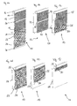
- FIGS 1a to 1f show an embodiment of an inventive Winding device in different Aufrolllagen, whereby the different Cover conditions can be clarified, which can be realized with the winding device are.
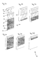
- FIGS. 2 a to 2 f show the reeling positions of FIG. 1 equivalent to those of FIG alternative embodiment of the present invention.
- Fig. 3 shows a further alternative embodiment of the present invention Invention.
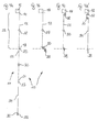
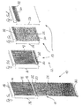
- Figures 4a to 4d show schematic side views of another alternative embodiment of the winding device according to the invention, consisting of three joined surface webs is formed.
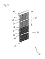
- Figures 5a to 5d show schematic perspective views of another alternative embodiment of the winding device according to the invention, consisting of two formed surface webs is formed, each having different lengths are.
- Winding device 10 comprises in the illustrated embodiment, a cover 11, which consists of two differently designed surface webs 12, 22nd composed.
- a first surface track 12 is provided with an upper longitudinal side 14 rigidly anchored to a bracket 16.
- a lower longitudinal side 18 of the first Surface web 12 is provided with an upper longitudinal side 20 of a second surface web 22 whose lower longitudinal side 24 hang loosely down or through here not shown guide elements can be guided laterally.
- a first winding element 26 Approximately in the middle between upper longitudinal side 14 and lower longitudinal side 18 of the first surface track 12 is a first winding element 26, which by a rotation for a two-ply winding the first tissue or surface web 12 can provide.
- the second surface web 22 is pulled upwards, so that a to be covered surface 28 with the second surface web 22 is variably covered.
- the first surface web 12 is considered loose woven net grid formed while the second surface web 22 denser woven or from a closed structure - for example, a foil or tarpaulin - can exist.
- a second winding member 30 is disposed, which is applied by an externally applied Rotational movement for a single-layer curling of the second surface web 22 of below can care.
- FIG. 1a The schematic perspective view of Fig. 1a shows the winding device 10 in the fully unrolled state. Both surface webs 12 and 22 are here shown unrolled to their respective full length.
- the cover 11 can basically any number of such surface webs, each preferred different properties in terms of their permeability to air, light, heat, Sound, etc., exist and thus be almost arbitrarily long.
- FIG Winding device 10 in practice normally no application, since the Covering 11 is significantly longer than the area to be covered 28.
- a corresponding winding of the cover 11 on the winding elements 26, 30 is the length of the cover 11 to the size of the surface to be covered 28th customized.
- the area to be covered 28 may, for example, a building opening, a Building side wall o. The like. Be.
- the area to be covered 28 can basically but also a variable opening or closing opening cross-section be within a building, a hall or any other room using the cover 11 with respect to its permeability to light, air, sound, Heat, UV radiation o. The like. Can be variably modified.
- the surface 28 can be variable completely with the first surface track 12 (Fig. 1b) or completely with the second surface track 22 (FIG. 1d) or with the first and the second Surface web in any proportions (Fig. 1c) imposed or alternatively opened and finally fully exposed ( Figures 1e and 1f).
- Fig. 1b illustrates a first operating position of the invention Winding device 10.
- the second surface web 22 is here almost completely rolled up on its lower longitudinal side 24 winding element 30 rolled up.
- winding element 30 rolled up.
- it can also be a lying below the surface to be covered 28, also expose the surface 32 to be covered.
- the first or upper surface to be covered 28 is imposed in the illustrated operating position of the first surface track 12, since this is in the fully unrolled state. That within the range the upper surface web 12 arranged winding element 26 is in this position completely free.
- Fig. 1c illustrates a partially rolled first surface web 12, in the the first winding element 26 is rotated relative to the illustration of FIG. 1b, so that the first surface web 12 is partially wound on this and thus shortened.
- the second winding element 30 are rotated in such a way that the second Surface web 22 is partially unrolled. This can, for example, by holding the lower winding element 30 happen.
- the lower winding element 30 but also an independent rotary motion by its own drive To run.
- the second surface track 22 is tracked in this way to the To be covered area 28 partially obscure.
- Execution of the two rotational movements remains in this adjustment to covering surface 28 at all times with the two surface sheets 12, 22nd covered, it only changes the relationship in which the two Surface webs 12, 22 contribute to cover the surface 28.
- this ratio is shifted to the second surface web 22 out.
- the first surface web 12 is completely rolled up onto the first winding element 26, whereby the surface to be covered 28 largely from the second fabric web 22nd is covered.
- the second winding element 30 can hereby almost completely rolled out be.
- Figures 1e and 1f show how by turning the second Winding element 30, a rolling up of the second, lower surface web 22 and thus an exposure of the surface 28 takes place from below.
- Fig. 1f is the fully open Position of the winding device 10 is reached, in which the surface 28 is largely uncovered is.
- FIGS. 1b to 1d can also be understood as meaning that the second winding element 30 in its height in the region at the lower edge of the covering surface 28 is rotatably fixed and not according to the figures 1a, 1e and 1f can be adjusted in height.
- the one to be covered Surface 28 are not completely exposed, but only optionally with the first Surface 12 (Fig. 1b), with the second surface 22 (Fig. 1d) or in any Division ratio with both surfaces 12, 22 (Fig. 1c) are covered.
- the second Winder element 30 can passively rotate here, since it is mounted laterally. This sets However, foresee that for a reverse rotation of the second winding element 30th what is, for example, by means of a suitable return spring, a suitable Other clamping device o. The like. Can be achieved.
- FIGS. 1a to 1f Winding device 10 The schematic perspective views of Figures 2a to 2f illustrate again the corresponding operating positions shown in FIGS. 1a to 1f Winding device 10.
- the upper Surface track 12 of several, juxtaposed ropes, cords or bands, which are analogous to the mesh fabric in Figures 1a to 1f for varying the Covering be rolled onto the corresponding winding element 26.
- FIG. 3 illustrates another Variant in which the second winding element 30 is not on the lower longitudinal side 24 of second surface track 22, but is disposed approximately in the middle thereof, so that Also, the second winding element 30 for a double-layer winding the corresponding fabric web 22 can provide, as in the first fabric web 12 according to the figures 1a to 1f and 2a to 2f is the case.
- the lower Long side 24 of the second surface 22 optionally also at the bottom of the zu Covering surface 28 and the opening may be fixed, for example.
- a rigid Anchoring In this case, no complete release of the opening is possible, but only an optional or partial covering with the first surface 12th or the second surface 22.
- Figures 4a to 4d show schematic side views of another alternative embodiment of the winding device 10 according to the invention, whose Covering element 11 of three joined surface webs 12, 22 and 34th is formed.
- FIG. 4a illustrates the cover 11 in the fully unrolled state, in which the first surface 12 with its upper longitudinal side 14 rigidly on the holder 16 is anchored.
- the lower longitudinal side 18 of the first surface 12 is connected to the upper Long side 20 of the second surface 22 is connected, the lower longitudinal side 24th in turn connected to an upper longitudinal side 35 of a third surface 34.
- the first winding element 26 is arranged.
- the second winding element 30 is arranged at the lower longitudinal side 36 of the third Surface 34.
- FIG. 4b illustrates that with the first Surface 12 covered surface 28.
- the second surface 22 and the third surface 34 are here on the second winding element 30 (double-layered) or on the third Winding element 38 (single layer) rolled up.
- Second and third winding element 30 and 38 are located near the lower edge of the surface 28 to be covered.
- FIG. 4c illustrates that with the second Surface 22 covered surface 28.
- the first surface 12 and the third surface 34 are here on the first winding element 26 (double-layered) or on the third Winding element 38 (single layer) rolled up.
- the first winding element 26 is located in this case near the upper edge of the surface 28 to be covered.
- the third Winding element 38 is in this case close to the lower edge of the to be covered Area 28.
- FIG. 4d illustrates that with the third Surface 34 covered surface 28.
- the first surface 12 and the second surface 22 are here on the first winding element 26 (double-layered) or on the second Winding element 30 (double-layered) rolled up.
- First and second winding element 26 and 30 are here near the upper edge of the surface to be covered 28.
- Das third winding element 38 is in this case close to the lower edge of the covering area 28.
- the winding device 10 shown in FIGS. 4 a to 4 d can, for example, be used for variable formation of heat, sound and / or light at least partially shielding partition in a production hall o.
- the like. Serve.
- the first surface 12 may be a UV light impermeable layer which allows Welding work is carried out in one area of the production hall without that the immediately adjacent areas are affected.
- the second Surface 22 may, for example, a sound largely impermeable or noise be insulating layer, which makes it possible to adjacent production areas to shield from noise-intensive work.
- the third surface 34 may, for example, a Heat insulating layer that can allow it in part of the hall Charging or manufacturing work to be carried out with open external doors, without In this case, adjacent to the area exposed to the weather.
- Figures 5a to 5d show schematic perspective views of another alternative embodiment of the winding device 10 according to the invention, which two adjoining surface sheets 12 and 22 is formed, respectively are different lengths.
- the schematic representation of Fig. 5a illustrates the Winding device 10 with unrolled cover 11 whose uppermost arranged first surface 12 with its upper longitudinal side 14 by means of rigid Attachment is anchored to the bracket 16.
- the area to be covered 28 corresponds in height about the length of the first surface 12 to its lower Longitudinal side 18, to which the second surface 22 connects.
- the first winding element 26 is located in this variant of Winding device 10 between the lower longitudinal side 18 of the first surface 12th and the upper longitudinal side 20 of the second surface 22, so that when turning the first winding element 26 is a two-ply winding of the first and second Surfaces 12 and 22 are superimposed (see Fig. 5c).
- the second winding element 30 is located on the lower longitudinal side 24 of the second surface 22, so that these are wound in a single layer during a rotation of the second winding element 30 can (see Fig. 5b).
- Winding element 30 may be a variable covering of the surface 28 with the second or the first surface 22 or 12 take place.
- the surface 28 of the first surface 12th covered ( Figure 5b).
- first winding element 26 When placed at the top of the surface 28 first winding element 26, surface 28 is covered by second surface 22 (FIG. 5c).
- second surface 22 When placed at the top of the surface 28 first winding element 26, surface 28 is covered by second surface 22 (FIG. 5c).
- intermediates between these two cover variants are by appropriate rotation of the first winding element 26 possible, in which case in each case the second winding element 30 is rotated, since when turning the first winding element 26, the second Surface 22 is unrolled from the second winding element 30 and rolled up on this.
- the surface 28 is largely released by the first rolled up Winding element 26 and the second winding element 30 is rolled up (Fig. 5d).
- the preferably flexible connections of the individual surfaces 12, 22 and / or 34 or tarpaulins, fabric webs or the like. at their respective adjacent Long sides can also be done in different ways.
- the surfaces can For example, welded together, riveted, sewn or otherwise unsolvable be connected to each other.
- detachable connections can also be used be meaningful, for example.
- the Connections can also be made through lockable and / or openable Connecting rings or be produced by means of connecting cords or bands, the through corresponding openings near the adjacent longitudinal sides of the Surfaces are looped or braided.
- there are many more Types of compounds conceivable as equivalents of each of the present invention are included.
Landscapes
- Engineering & Computer Science (AREA)
- Structural Engineering (AREA)
- Architecture (AREA)
- Civil Engineering (AREA)
- Operating, Guiding And Securing Of Roll- Type Closing Members (AREA)
- Winding Of Webs (AREA)
- Rolls And Other Rotary Bodies (AREA)
- Massaging Devices (AREA)
- Blinds (AREA)
Priority Applications (1)
| Application Number | Priority Date | Filing Date | Title |
|---|---|---|---|
| PL04024283T PL1522671T3 (pl) | 2003-10-12 | 2004-10-12 | Urządzenie zwijane, zwłaszcza żaluzja zwijana |
Applications Claiming Priority (2)
| Application Number | Priority Date | Filing Date | Title |
|---|---|---|---|
| DE20315853U DE20315853U1 (de) | 2003-10-12 | 2003-10-12 | Wickelverfahren für variable Bedeckung von Flächen mit unterschiedlichen Gewebearten |
| DE20315853U | 2003-10-12 |
Publications (4)
| Publication Number | Publication Date |
|---|---|
| EP1522671A2 true EP1522671A2 (fr) | 2005-04-13 |
| EP1522671A3 EP1522671A3 (fr) | 2005-11-09 |
| EP1522671B1 EP1522671B1 (fr) | 2012-02-15 |
| EP1522671B9 EP1522671B9 (fr) | 2012-08-08 |
Family
ID=31984636
Family Applications (1)
| Application Number | Title | Priority Date | Filing Date |
|---|---|---|---|
| EP04024283A Expired - Lifetime EP1522671B9 (fr) | 2003-10-12 | 2004-10-12 | Store à rouleau |
Country Status (4)
| Country | Link |
|---|---|
| EP (1) | EP1522671B9 (fr) |
| AT (1) | ATE545759T1 (fr) |
| DE (1) | DE20315853U1 (fr) |
| PL (1) | PL1522671T3 (fr) |
Cited By (8)
| Publication number | Priority date | Publication date | Assignee | Title |
|---|---|---|---|---|
| GB2431190A (en) * | 2005-10-13 | 2007-04-18 | John Benjamin Slater | Adjustable screen |
| EP1522671B1 (fr) * | 2003-10-12 | 2012-02-15 | Markus Zettl | Store à rouleau |
| US20160130873A1 (en) * | 2014-11-10 | 2016-05-12 | Lock Antriebstechnik Gmbh | Winding device for covering of building openings |
| JP2022024585A (ja) * | 2020-07-28 | 2022-02-09 | Ykk Ap株式会社 | ロールスクリーンユニット |
| CN116491345A (zh) * | 2023-05-06 | 2023-07-28 | 北京丰隆科技有限公司 | 卷被机构及温室大棚 |
| CN116548316A (zh) * | 2023-04-19 | 2023-08-08 | 内蒙古奥科斯牧业有限公司 | 一种基于太阳光照角度的可调式采光采暖牛棚 |
| JP2023170644A (ja) * | 2022-05-19 | 2023-12-01 | 株式会社大林組 | 遮蔽部材 |
| JP2023170646A (ja) * | 2022-05-19 | 2023-12-01 | 株式会社大林組 | 遮蔽装置 |
Families Citing this family (1)
| Publication number | Priority date | Publication date | Assignee | Title |
|---|---|---|---|---|
| AU2020391113A1 (en) | 2019-11-25 | 2022-05-26 | Hunter Douglas Inc. | Covering with multiple shade configurations |
Citations (5)
| Publication number | Priority date | Publication date | Assignee | Title |
|---|---|---|---|---|
| DE9210938U1 (de) | 1992-08-15 | 1992-12-17 | Remis Gesellschaft für Entwicklung und Vertrieb von technischen Elementen mbH Köln, 5000 Köln | Rollo-Vorrichtung |
| EP0567030A2 (fr) | 1992-04-21 | 1993-10-27 | Hüppe Form Sonnenschutz- und Raumtrennsysteme GmbH | Couverture en plusieurs stores parallèles |
| DE20214076U1 (de) | 2002-09-10 | 2003-05-08 | Bvba Vervaeke, Ruiselede | Vorrichtung zum Abschirmen eines Raumes |
| DE10336944A1 (de) | 2002-08-07 | 2004-02-26 | Lock Antriebstechnik Gmbh | Wickeljalousie |
| DE20320335U1 (de) | 2003-08-07 | 2004-06-17 | Lock Antriebstechnik Gmbh | Wickeljalousie |
Family Cites Families (5)
| Publication number | Priority date | Publication date | Assignee | Title |
|---|---|---|---|---|
| US3306344A (en) * | 1965-10-11 | 1967-02-28 | R L Kuss And Company Inc | Flexible closure |
| FR2211585B1 (fr) * | 1972-12-21 | 1976-08-27 | Nijmegen Metaal Nv | |
| US4809760A (en) * | 1979-03-14 | 1989-03-07 | Lew Hyok S | Self-coiling partition |
| SE524182C2 (sv) * | 2002-03-13 | 2004-07-06 | Ronny Kogsta | Rullgardinssystem, förfarande för montering av rullgardin samt monteringsfärdig rullgardinssats |
| DE20315853U1 (de) * | 2003-10-12 | 2004-03-04 | Zettl, Markus | Wickelverfahren für variable Bedeckung von Flächen mit unterschiedlichen Gewebearten |
-
2003
- 2003-10-12 DE DE20315853U patent/DE20315853U1/de not_active Expired - Lifetime
-
2004
- 2004-10-12 PL PL04024283T patent/PL1522671T3/pl unknown
- 2004-10-12 AT AT04024283T patent/ATE545759T1/de active
- 2004-10-12 EP EP04024283A patent/EP1522671B9/fr not_active Expired - Lifetime
Patent Citations (5)
| Publication number | Priority date | Publication date | Assignee | Title |
|---|---|---|---|---|
| EP0567030A2 (fr) | 1992-04-21 | 1993-10-27 | Hüppe Form Sonnenschutz- und Raumtrennsysteme GmbH | Couverture en plusieurs stores parallèles |
| DE9210938U1 (de) | 1992-08-15 | 1992-12-17 | Remis Gesellschaft für Entwicklung und Vertrieb von technischen Elementen mbH Köln, 5000 Köln | Rollo-Vorrichtung |
| DE10336944A1 (de) | 2002-08-07 | 2004-02-26 | Lock Antriebstechnik Gmbh | Wickeljalousie |
| DE20214076U1 (de) | 2002-09-10 | 2003-05-08 | Bvba Vervaeke, Ruiselede | Vorrichtung zum Abschirmen eines Raumes |
| DE20320335U1 (de) | 2003-08-07 | 2004-06-17 | Lock Antriebstechnik Gmbh | Wickeljalousie |
Cited By (11)
| Publication number | Priority date | Publication date | Assignee | Title |
|---|---|---|---|---|
| EP1522671B1 (fr) * | 2003-10-12 | 2012-02-15 | Markus Zettl | Store à rouleau |
| GB2431190A (en) * | 2005-10-13 | 2007-04-18 | John Benjamin Slater | Adjustable screen |
| GB2431190B (en) * | 2005-10-13 | 2010-02-24 | John Benjamin Slater | Adjustable screen |
| US20160130873A1 (en) * | 2014-11-10 | 2016-05-12 | Lock Antriebstechnik Gmbh | Winding device for covering of building openings |
| US10041295B2 (en) * | 2014-11-10 | 2018-08-07 | Lock Antriebstechnik Gmbh | Winding device for covering of building openings |
| JP2022024585A (ja) * | 2020-07-28 | 2022-02-09 | Ykk Ap株式会社 | ロールスクリーンユニット |
| JP7547103B2 (ja) | 2020-07-28 | 2024-09-09 | Ykk Ap株式会社 | ロールスクリーンユニット |
| JP2023170644A (ja) * | 2022-05-19 | 2023-12-01 | 株式会社大林組 | 遮蔽部材 |
| JP2023170646A (ja) * | 2022-05-19 | 2023-12-01 | 株式会社大林組 | 遮蔽装置 |
| CN116548316A (zh) * | 2023-04-19 | 2023-08-08 | 内蒙古奥科斯牧业有限公司 | 一种基于太阳光照角度的可调式采光采暖牛棚 |
| CN116491345A (zh) * | 2023-05-06 | 2023-07-28 | 北京丰隆科技有限公司 | 卷被机构及温室大棚 |
Also Published As
| Publication number | Publication date |
|---|---|
| ATE545759T1 (de) | 2012-03-15 |
| PL1522671T3 (pl) | 2012-07-31 |
| EP1522671B9 (fr) | 2012-08-08 |
| EP1522671A3 (fr) | 2005-11-09 |
| EP1522671B1 (fr) | 2012-02-15 |
| DE20315853U1 (de) | 2004-03-04 |
Similar Documents
| Publication | Publication Date | Title |
|---|---|---|
| DE69637425T2 (de) | Abdichtbare Abdeckung | |
| DE69231657T2 (de) | Doppellagige Verschattungseinrichtung | |
| DE3521084C2 (fr) | ||
| EP0089657B1 (fr) | Store isolant | |
| EP1522671B1 (fr) | Store à rouleau | |
| DE3643233A1 (de) | Vorgefertigte fenster- und rolladenvorrichtung fuer haeuser u.dgl. | |
| EP0426046A2 (fr) | Moustiquaire-grille à rouleau | |
| DE202018105151U1 (de) | Aufrollbare Markise | |
| DE69004825T2 (de) | Mobiles Verschlussmittel für Wandöffnung. | |
| DE202004020298U1 (de) | Wickelvorrichtung, insbesondere Wickeljalousie | |
| EP1300541B1 (fr) | Caisson de volet roulant | |
| DE29916738U1 (de) | Rolloeinrichtung | |
| DE19805272A1 (de) | Einrichtung zum Schützen, Abdecken, Verschließen, Abtrennen o. dgl. Abgrenzen von Bereichen | |
| DE19844678C2 (de) | Als Seitenwand eines Stalls ausgebildete Belüftungsanlage | |
| EP0693614A1 (fr) | Dispositif d'ombrage | |
| DE8633840U1 (de) | Vorgefertigte Fenster- und Rolladenvorrichtung für Häuser u. dgl. | |
| DE19515426A1 (de) | Abdeckungsvorrichtung | |
| DE2527383A1 (de) | Dachflaechenfenster | |
| DE102007002075B4 (de) | Rollladenkasten mit einer Walze und einem darauf gewickelten Rollladen | |
| DE2639275A1 (de) | Rollo fuer fenster, tueren oder dergleichen | |
| WO2023061917A1 (fr) | Dispositif d'aménagement de façade à fixer dans la zone d'une ouverture extérieure d'un bâtiment | |
| DE7707746U1 (de) | Fahrzeug, insbesondere wohnwagen oder wohnmobil | |
| DE2242672C3 (de) | Nichtfaltbares Schiebedach, insbesondere zur Abdeckung von Dachausschnitten | |
| WO2021069639A1 (fr) | Dispositif pour agir sur le rythme jour/nuit d'une plante | |
| DE102010052501A1 (de) | Verschattungsvorrichtung für Fenster oder Türen, insbesondere Rollladen |
Legal Events
| Date | Code | Title | Description |
|---|---|---|---|
| PUAI | Public reference made under article 153(3) epc to a published international application that has entered the european phase |
Free format text: ORIGINAL CODE: 0009012 |
|
| AK | Designated contracting states |
Kind code of ref document: A2 Designated state(s): AT BE BG CH CY CZ DE DK EE ES FI FR GB GR HU IE IT LI LU MC NL PL PT RO SE SI SK TR |
|
| AX | Request for extension of the european patent |
Extension state: AL HR LT LV MK |
|
| PUAL | Search report despatched |
Free format text: ORIGINAL CODE: 0009013 |
|
| AK | Designated contracting states |
Kind code of ref document: A3 Designated state(s): AT BE BG CH CY CZ DE DK EE ES FI FR GB GR HU IE IT LI LU MC NL PL PT RO SE SI SK TR |
|
| AX | Request for extension of the european patent |
Extension state: AL HR LT LV MK |
|
| 17P | Request for examination filed |
Effective date: 20060221 |
|
| RAP1 | Party data changed (applicant data changed or rights of an application transferred) |
Owner name: ZETTL, MARKUS |
|
| RIN1 | Information on inventor provided before grant (corrected) |
Inventor name: ZETTL, MARKUS |
|
| AKX | Designation fees paid |
Designated state(s): AT BE BG CH CY CZ DE DK EE ES FI FR GB GR HU IE IT LI LU MC NL PL PT RO SE SI SK TR |
|
| 17Q | First examination report despatched |
Effective date: 20060904 |
|
| GRAP | Despatch of communication of intention to grant a patent |
Free format text: ORIGINAL CODE: EPIDOSNIGR1 |
|
| GRAS | Grant fee paid |
Free format text: ORIGINAL CODE: EPIDOSNIGR3 |
|
| GRAA | (expected) grant |
Free format text: ORIGINAL CODE: 0009210 |
|
| AK | Designated contracting states |
Kind code of ref document: B1 Designated state(s): AT BE BG CH CY CZ DE DK EE ES FI FR GB GR HU IE IT LI LU MC NL PL PT RO SE SI SK TR |
|
| REG | Reference to a national code |
Ref country code: GB Ref legal event code: FG4D Free format text: NOT ENGLISH Ref country code: CH Ref legal event code: EP |
|
| REG | Reference to a national code |
Ref country code: IE Ref legal event code: FG4D Free format text: LANGUAGE OF EP DOCUMENT: GERMAN |
|
| REG | Reference to a national code |
Ref country code: AT Ref legal event code: REF Ref document number: 545759 Country of ref document: AT Kind code of ref document: T Effective date: 20120315 |
|
| REG | Reference to a national code |
Ref country code: DE Ref legal event code: R096 Ref document number: 502004013293 Country of ref document: DE Effective date: 20120412 |
|
| REG | Reference to a national code |
Ref country code: RO Ref legal event code: EPE |
|
| REG | Reference to a national code |
Ref country code: NL Ref legal event code: T3 |
|
| REG | Reference to a national code |
Ref country code: PL Ref legal event code: T3 |
|
| PG25 | Lapsed in a contracting state [announced via postgrant information from national office to epo] |
Ref country code: FI Free format text: LAPSE BECAUSE OF FAILURE TO SUBMIT A TRANSLATION OF THE DESCRIPTION OR TO PAY THE FEE WITHIN THE PRESCRIBED TIME-LIMIT Effective date: 20120215 Ref country code: PT Free format text: LAPSE BECAUSE OF FAILURE TO SUBMIT A TRANSLATION OF THE DESCRIPTION OR TO PAY THE FEE WITHIN THE PRESCRIBED TIME-LIMIT Effective date: 20120615 Ref country code: GR Free format text: LAPSE BECAUSE OF FAILURE TO SUBMIT A TRANSLATION OF THE DESCRIPTION OR TO PAY THE FEE WITHIN THE PRESCRIBED TIME-LIMIT Effective date: 20120516 |
|
| REG | Reference to a national code |
Ref country code: IE Ref legal event code: FD4D |
|
| PG25 | Lapsed in a contracting state [announced via postgrant information from national office to epo] |
Ref country code: CY Free format text: LAPSE BECAUSE OF FAILURE TO SUBMIT A TRANSLATION OF THE DESCRIPTION OR TO PAY THE FEE WITHIN THE PRESCRIBED TIME-LIMIT Effective date: 20120215 |
|
| PG25 | Lapsed in a contracting state [announced via postgrant information from national office to epo] |
Ref country code: SI Free format text: LAPSE BECAUSE OF FAILURE TO SUBMIT A TRANSLATION OF THE DESCRIPTION OR TO PAY THE FEE WITHIN THE PRESCRIBED TIME-LIMIT Effective date: 20120215 Ref country code: SE Free format text: LAPSE BECAUSE OF FAILURE TO SUBMIT A TRANSLATION OF THE DESCRIPTION OR TO PAY THE FEE WITHIN THE PRESCRIBED TIME-LIMIT Effective date: 20120215 Ref country code: DK Free format text: LAPSE BECAUSE OF FAILURE TO SUBMIT A TRANSLATION OF THE DESCRIPTION OR TO PAY THE FEE WITHIN THE PRESCRIBED TIME-LIMIT Effective date: 20120215 Ref country code: EE Free format text: LAPSE BECAUSE OF FAILURE TO SUBMIT A TRANSLATION OF THE DESCRIPTION OR TO PAY THE FEE WITHIN THE PRESCRIBED TIME-LIMIT Effective date: 20120215 Ref country code: IE Free format text: LAPSE BECAUSE OF FAILURE TO SUBMIT A TRANSLATION OF THE DESCRIPTION OR TO PAY THE FEE WITHIN THE PRESCRIBED TIME-LIMIT Effective date: 20120215 |
|
| REG | Reference to a national code |
Ref country code: HU Ref legal event code: AG4A Ref document number: E014500 Country of ref document: HU |
|
| PG25 | Lapsed in a contracting state [announced via postgrant information from national office to epo] |
Ref country code: IT Free format text: LAPSE BECAUSE OF FAILURE TO SUBMIT A TRANSLATION OF THE DESCRIPTION OR TO PAY THE FEE WITHIN THE PRESCRIBED TIME-LIMIT Effective date: 20120215 Ref country code: SK Free format text: LAPSE BECAUSE OF FAILURE TO SUBMIT A TRANSLATION OF THE DESCRIPTION OR TO PAY THE FEE WITHIN THE PRESCRIBED TIME-LIMIT Effective date: 20120215 |
|
| PLBE | No opposition filed within time limit |
Free format text: ORIGINAL CODE: 0009261 |
|
| STAA | Information on the status of an ep patent application or granted ep patent |
Free format text: STATUS: NO OPPOSITION FILED WITHIN TIME LIMIT |
|
| 26N | No opposition filed |
Effective date: 20121116 |
|
| REG | Reference to a national code |
Ref country code: DE Ref legal event code: R097 Ref document number: 502004013293 Country of ref document: DE Effective date: 20121116 |
|
| PG25 | Lapsed in a contracting state [announced via postgrant information from national office to epo] |
Ref country code: ES Free format text: LAPSE BECAUSE OF FAILURE TO SUBMIT A TRANSLATION OF THE DESCRIPTION OR TO PAY THE FEE WITHIN THE PRESCRIBED TIME-LIMIT Effective date: 20120526 |
|
| PG25 | Lapsed in a contracting state [announced via postgrant information from national office to epo] |
Ref country code: MC Free format text: LAPSE BECAUSE OF NON-PAYMENT OF DUE FEES Effective date: 20121031 |
|
| PG25 | Lapsed in a contracting state [announced via postgrant information from national office to epo] |
Ref country code: BG Free format text: LAPSE BECAUSE OF FAILURE TO SUBMIT A TRANSLATION OF THE DESCRIPTION OR TO PAY THE FEE WITHIN THE PRESCRIBED TIME-LIMIT Effective date: 20120515 |
|
| PG25 | Lapsed in a contracting state [announced via postgrant information from national office to epo] |
Ref country code: LU Free format text: LAPSE BECAUSE OF NON-PAYMENT OF DUE FEES Effective date: 20121012 |
|
| REG | Reference to a national code |
Ref country code: FR Ref legal event code: PLFP Year of fee payment: 12 |
|
| REG | Reference to a national code |
Ref country code: FR Ref legal event code: PLFP Year of fee payment: 13 |
|
| PGFP | Annual fee paid to national office [announced via postgrant information from national office to epo] |
Ref country code: RO Payment date: 20160927 Year of fee payment: 13 |
|
| PGFP | Annual fee paid to national office [announced via postgrant information from national office to epo] |
Ref country code: TR Payment date: 20160927 Year of fee payment: 13 |
|
| PGFP | Annual fee paid to national office [announced via postgrant information from national office to epo] |
Ref country code: HU Payment date: 20161019 Year of fee payment: 13 Ref country code: CZ Payment date: 20161011 Year of fee payment: 13 |
|
| REG | Reference to a national code |
Ref country code: FR Ref legal event code: PLFP Year of fee payment: 14 |
|
| PG25 | Lapsed in a contracting state [announced via postgrant information from national office to epo] |
Ref country code: CZ Free format text: LAPSE BECAUSE OF NON-PAYMENT OF DUE FEES Effective date: 20171012 |
|
| PG25 | Lapsed in a contracting state [announced via postgrant information from national office to epo] |
Ref country code: RO Free format text: LAPSE BECAUSE OF NON-PAYMENT OF DUE FEES Effective date: 20171012 Ref country code: HU Free format text: LAPSE BECAUSE OF NON-PAYMENT OF DUE FEES Effective date: 20171013 |
|
| REG | Reference to a national code |
Ref country code: FR Ref legal event code: PLFP Year of fee payment: 15 |
|
| PGFP | Annual fee paid to national office [announced via postgrant information from national office to epo] |
Ref country code: NL Payment date: 20201028 Year of fee payment: 17 |
|
| PGFP | Annual fee paid to national office [announced via postgrant information from national office to epo] |
Ref country code: FR Payment date: 20201021 Year of fee payment: 17 |
|
| PGFP | Annual fee paid to national office [announced via postgrant information from national office to epo] |
Ref country code: GB Payment date: 20211022 Year of fee payment: 18 |
|
| PGFP | Annual fee paid to national office [announced via postgrant information from national office to epo] |
Ref country code: BE Payment date: 20211020 Year of fee payment: 18 |
|
| PGFP | Annual fee paid to national office [announced via postgrant information from national office to epo] |
Ref country code: PL Payment date: 20211011 Year of fee payment: 18 |
|
| REG | Reference to a national code |
Ref country code: NL Ref legal event code: MM Effective date: 20211101 |
|
| PG25 | Lapsed in a contracting state [announced via postgrant information from national office to epo] |
Ref country code: TR Free format text: LAPSE BECAUSE OF NON-PAYMENT OF DUE FEES Effective date: 20171012 |
|
| PG25 | Lapsed in a contracting state [announced via postgrant information from national office to epo] |
Ref country code: NL Free format text: LAPSE BECAUSE OF NON-PAYMENT OF DUE FEES Effective date: 20211101 |
|
| PG25 | Lapsed in a contracting state [announced via postgrant information from national office to epo] |
Ref country code: FR Free format text: LAPSE BECAUSE OF NON-PAYMENT OF DUE FEES Effective date: 20211031 |
|
| REG | Reference to a national code |
Ref country code: BE Ref legal event code: MM Effective date: 20221031 |
|
| GBPC | Gb: european patent ceased through non-payment of renewal fee |
Effective date: 20221012 |
|
| PG25 | Lapsed in a contracting state [announced via postgrant information from national office to epo] |
Ref country code: BE Free format text: LAPSE BECAUSE OF NON-PAYMENT OF DUE FEES Effective date: 20221031 |
|
| PG25 | Lapsed in a contracting state [announced via postgrant information from national office to epo] |
Ref country code: GB Free format text: LAPSE BECAUSE OF NON-PAYMENT OF DUE FEES Effective date: 20221012 |
|
| PG25 | Lapsed in a contracting state [announced via postgrant information from national office to epo] |
Ref country code: PL Free format text: LAPSE BECAUSE OF NON-PAYMENT OF DUE FEES Effective date: 20221012 |
|
| PGFP | Annual fee paid to national office [announced via postgrant information from national office to epo] |
Ref country code: DE Payment date: 20231020 Year of fee payment: 20 Ref country code: CH Payment date: 20231102 Year of fee payment: 20 Ref country code: AT Payment date: 20231020 Year of fee payment: 20 |
|
| REG | Reference to a national code |
Ref country code: DE Ref legal event code: R071 Ref document number: 502004013293 Country of ref document: DE |
|
| REG | Reference to a national code |
Ref country code: CH Ref legal event code: PL |
|
| REG | Reference to a national code |
Ref country code: AT Ref legal event code: MK07 Ref document number: 545759 Country of ref document: AT Kind code of ref document: T Effective date: 20241012 |