EP1522671A2 - Roller shade - Google Patents
Roller shade Download PDFInfo
- Publication number
- EP1522671A2 EP1522671A2 EP04024283A EP04024283A EP1522671A2 EP 1522671 A2 EP1522671 A2 EP 1522671A2 EP 04024283 A EP04024283 A EP 04024283A EP 04024283 A EP04024283 A EP 04024283A EP 1522671 A2 EP1522671 A2 EP 1522671A2
- Authority
- EP
- European Patent Office
- Prior art keywords
- winding
- winding device
- web
- webs
- surface web
- Prior art date
- Legal status (The legal status is an assumption and is not a legal conclusion. Google has not performed a legal analysis and makes no representation as to the accuracy of the status listed.)
- Granted
Links
Images
Classifications
-
- E—FIXED CONSTRUCTIONS
- E06—DOORS, WINDOWS, SHUTTERS, OR ROLLER BLINDS IN GENERAL; LADDERS
- E06B—FIXED OR MOVABLE CLOSURES FOR OPENINGS IN BUILDINGS, VEHICLES, FENCES OR LIKE ENCLOSURES IN GENERAL, e.g. DOORS, WINDOWS, BLINDS, GATES
- E06B9/00—Screening or protective devices for wall or similar openings, with or without operating or securing mechanisms; Closures of similar construction
- E06B9/24—Screens or other constructions affording protection against light, especially against sunshine; Similar screens for privacy or appearance; Slat blinds
- E06B9/40—Roller blinds
-
- E—FIXED CONSTRUCTIONS
- E06—DOORS, WINDOWS, SHUTTERS, OR ROLLER BLINDS IN GENERAL; LADDERS
- E06B—FIXED OR MOVABLE CLOSURES FOR OPENINGS IN BUILDINGS, VEHICLES, FENCES OR LIKE ENCLOSURES IN GENERAL, e.g. DOORS, WINDOWS, BLINDS, GATES
- E06B9/00—Screening or protective devices for wall or similar openings, with or without operating or securing mechanisms; Closures of similar construction
- E06B9/56—Operating, guiding or securing devices or arrangements for roll-type closures; Spring drums; Tape drums; Counterweighting arrangements therefor
- E06B9/64—Operating, guiding or securing devices or arrangements for roll-type closures; Spring drums; Tape drums; Counterweighting arrangements therefor with lowerable roller
-
- E—FIXED CONSTRUCTIONS
- E06—DOORS, WINDOWS, SHUTTERS, OR ROLLER BLINDS IN GENERAL; LADDERS
- E06B—FIXED OR MOVABLE CLOSURES FOR OPENINGS IN BUILDINGS, VEHICLES, FENCES OR LIKE ENCLOSURES IN GENERAL, e.g. DOORS, WINDOWS, BLINDS, GATES
- E06B9/00—Screening or protective devices for wall or similar openings, with or without operating or securing mechanisms; Closures of similar construction
- E06B9/56—Operating, guiding or securing devices or arrangements for roll-type closures; Spring drums; Tape drums; Counterweighting arrangements therefor
- E06B9/66—Operating, guiding or securing devices or arrangements for roll-type closures; Spring drums; Tape drums; Counterweighting arrangements therefor with a roller situated at the bottom
-
- E—FIXED CONSTRUCTIONS
- E06—DOORS, WINDOWS, SHUTTERS, OR ROLLER BLINDS IN GENERAL; LADDERS
- E06B—FIXED OR MOVABLE CLOSURES FOR OPENINGS IN BUILDINGS, VEHICLES, FENCES OR LIKE ENCLOSURES IN GENERAL, e.g. DOORS, WINDOWS, BLINDS, GATES
- E06B9/00—Screening or protective devices for wall or similar openings, with or without operating or securing mechanisms; Closures of similar construction
- E06B9/24—Screens or other constructions affording protection against light, especially against sunshine; Similar screens for privacy or appearance; Slat blinds
- E06B2009/2423—Combinations of at least two screens
- E06B2009/2441—Screens joined one below the other
-
- E—FIXED CONSTRUCTIONS
- E06—DOORS, WINDOWS, SHUTTERS, OR ROLLER BLINDS IN GENERAL; LADDERS
- E06B—FIXED OR MOVABLE CLOSURES FOR OPENINGS IN BUILDINGS, VEHICLES, FENCES OR LIKE ENCLOSURES IN GENERAL, e.g. DOORS, WINDOWS, BLINDS, GATES
- E06B9/00—Screening or protective devices for wall or similar openings, with or without operating or securing mechanisms; Closures of similar construction
- E06B9/24—Screens or other constructions affording protection against light, especially against sunshine; Similar screens for privacy or appearance; Slat blinds
- E06B2009/2423—Combinations of at least two screens
- E06B2009/2447—Parallel screens
- E06B2009/2458—Parallel screens moving simultaneously
-
- E—FIXED CONSTRUCTIONS
- E06—DOORS, WINDOWS, SHUTTERS, OR ROLLER BLINDS IN GENERAL; LADDERS
- E06B—FIXED OR MOVABLE CLOSURES FOR OPENINGS IN BUILDINGS, VEHICLES, FENCES OR LIKE ENCLOSURES IN GENERAL, e.g. DOORS, WINDOWS, BLINDS, GATES
- E06B9/00—Screening or protective devices for wall or similar openings, with or without operating or securing mechanisms; Closures of similar construction
- E06B9/24—Screens or other constructions affording protection against light, especially against sunshine; Similar screens for privacy or appearance; Slat blinds
- E06B9/40—Roller blinds
- E06B2009/405—Two rollers
Definitions
- the present invention relates to a winding device, in particular a Winding blind with the features of the independent claim.
- Venetian blinds where a rotatable winding roll is arranged above an opening to be covered, allow only a Aufund Unrolling the fabric web on the winding roll and thus a variable opening upwards.
- Such Venetian blinds serve, for example, for shading Window openings in houses and apartments.
- Venetian blinds are used, for example, in greenhouses.
- the Fabric web can in such conventional winding devices of only be opened down to the top, which is unfavorable for some applications.
- DE 202 14 076 U1 Another system for variable ventilation and / or shading of Buildings or rooms is known from DE 202 14 076 U1.
- This device comprises an upper and a lower roll system for winding and unrolling a screen, so that different tissue types are optional on the top or bottom Wrapping roll can be rolled up.
- the room is, for example, with a Tight fabric type shaded or by means of a very marmaschig woven Fabric type made air and translucent.
- the two winding elements are each rigidly anchored above and below the room opening.
- Such a device can not extend over any width, because the differences in the Diameters of the upper and lower roll at any time by means of a Clamping device must be balanced and the storage of the upper Winding roll is problematic for very wide and thus heavy shielding.
- the use of such a device to cover a very wide Carteres thus requires a juxtaposition of several such devices.
- a similar kind of roller blind device with a first and a different provided second material web, which are each wound around a winding axis, and each with a first end in the region of its winding axis on a holder are fixed, is further known from DE 92 10 938 U1.
- the first and the second Material web are firmly connected together at their free second end and the Holders are movable relative to each other toward or away from each other, wherein in these movements, the two webs are up or unwound.
- An object of the present invention is to provide a winding device for variable covering of surfaces, for example openings in rooms or buildings, with Covering elements of different textures or cropping these surfaces which is simple to set up and operate and which is also suitable for large areas is suitable.
- the winding device with the features of independent claim allows variable coverage of areas, eg. Openings in rooms or buildings, with cover elements, where a Cover element at least two or more differently procured, includes adjacent surface webs and being associated with the arrangement of two or more winding elements, the area to be covered as required, each with at least one surface track of a constant selectable condition can remain covered.
- a Cover element at least two or more differently procured, includes adjacent surface webs and being associated with the arrangement of two or more winding elements, the area to be covered as required, each with at least one surface track of a constant selectable condition can remain covered.
- a Cover element at least two or more differently procured, includes adjacent surface webs and being associated with the arrangement of two or more winding elements, the area to be covered as required, each with at least one surface track of a constant selectable condition can remain covered.
- the present invention is different in the range of at least two surface webs Textures each arranged at least one rotatable winding element, wherein the respective surface paths each variable
- the winding device With the winding device according to the invention, it is possible to one Covering or releasing opening in a housing, a building, a Stable, a greenhouse or the like to open or close variably to shade or largely release.
- the inventive Winding device is an advantageous development, since the currently known Venetian blind devices with upper rigid attachment variable ventilation of one upper opening with simultaneous coverage of a lower area of the opening is not allow.
- winding device in addition to those already mentioned, there are numerous other applications for the winding device according to the invention.
- such winding devices be used as mobile partitions in the outer and / or interior, for example.
- variably manageable fire protection walls, Soundproof walls and / or noise barriers are realized only in the If necessary, pulled out of their upper suspension and when not in use again can be rolled.
- UV barriers for example for shielding welding workplaces.
- the winding device according to the invention can be used advantageously.
- the mentioned Use cases or parts thereof are each by means of a winding device easily realizable, since the different tissue or surface webs be adapted to the respective purposes and be rolled out accordingly can.
- surface web or “Surfaces of different textures” are used, so are with it basically includes sections of shielding elements and includes, which optionally from different types of fabric such as net mesh or conventional more or less densely woven fabrics, of strings running side by side, Ropes or flat bands, or even from closed surfaces such as.
- Plastic or synthetic fiber films or tarpaulins can exist.
- the like designed sections can each be made of natural and / or synthetic fibers or foils o.
- a preferred embodiment of the present invention extends Such a portion of a shielding over the entire width or Length of the winding device in the longitudinal direction of the winding elements and corresponds in its length or width approximately the length or width of the Covered area, so that a single such section at appropriate Winding the winding device can cover the entire area to be covered.
- a typical width of a winding device according to the invention can, for example, up to 20 Meters or more. Depending on the need, however, are also much larger Widths variably coverable.
- any number of such sections are each fixed at their longitudinal edges connected together, so that the entire shielding be arbitrarily long can.
- According to the invention is always such a large proportion of the shielding on the rolled up at least two winding elements that the length of the exposed, the Surface covering portion of the shielding member maximum of the height or width of the corresponds to the area to be covered.
- At least one winding element is arranged in each case.
- the Winding elements of the winding device according to the invention are in particular in one Arranged middle region of their respective associated surface track and at this place firmly connected to the corresponding surface track, so that at a rotation of the corresponding winding element emanating from its center two-ply winding of the respective surface web around the winding element around he follows.
- two or more winding elements within a Be arranged portion of the shielding must be in each case so be distributed over the area of the surface track that they are during the Winding process does not interfere with each other. For example. must when using two Wickelelementen per surface web the first about in the upper quarter and the second be arranged in the lower fourth of the surface web.
- a arranged in the region of the lowest arranged surface web Winding element can optionally be arranged at the lower end of the surface web be, so that at least the lowermost surface web of a lower edge can be wound single-layer starting.
- By winding the bottom one Surface track can be an exemption of the area, eg. The building or Room opening, done from below.
- it is alternatively possible with a already rolled up lower surface to roll up only the upper winding element and at the same time to fix the lower winding element in its height. Possibly. can do this lower winding element to be rotatably anchored, so that the surface to be covered not completely exposed, but only with one of several optional Surfaces can be covered.
- the Winding elements not firmly anchored in the direction of movement of the cover, but lead during the winding process in the direction of movement of the Covering directed movement, resulting from the shortening or Extension of the exposed surface of the respective surface track results.
- a hanging embodiment of the present invention moves Wrapping element during the winding up and during the Unwinding down, if not another, overlying Winding performs a winding process, the absolute up or Downward movement of the lower winding element compensates.
- the winding elements can - like the cover - hang freely in the room. Alternatively you can with Side areas that can protrude laterally beyond the cover, in Guide elements, eg. Guide rails, engage.
- one or more of the winding elements rotatable and in be stored predetermined height, so that no complete release of the Covering opening is possible, but only an optional covering with a or a partial covering with several of the existing surfaces.
- the drive of the winding elements - these are in particular known Winding tubes, winding rods or the like - can be manually, carried out by electric motor or otherwise. For example. can engine revolutions By means of cardan shafts, toothed belt or V-belt mechanisms on the Winding elements are transferred, or motors can each within the Be arranged winding elements.
- Such winding drives are known and not part of the present invention. They are therefore not explained in detail at this point. Examples of drives of winding elements, as described in the present The invention can be used, inter alia, in DE 202 14 076 U1, in EP 0 567 030 A2, in DE 203 20 335 U1 or in DE 103 36 944 A1.
- An uppermost surface web can, for example, at the lower end a Have winding element, so that when it turns a double-layer winding the first surface track and a subsequent second Surface track takes place.
- the second surface sheet is preferably longer than the second surface sheet first track, for example, twice as long as this.
- the second Surface web have another winding element, so that a variable Covering a surface to be covered by means of the first and / or the second Surface web or its exposure at fully rolled up first and second Rail is possible.
- the uppermost arranged surface web according to the invention at a Upper edge of a rigid attachment can be the top of the top Section of the shielding rigid to a fixed part of the building, eg. At one Be attached outer wall, so that the upper end of the winding device in solid Position is anchored.
- the attachment can alternatively by the connection with a rigid holding device, eg. A rail done. This rail can turn be attached firmly to a building part.
- she can also use one Lifting device combined for uniform lifting or lowering of the Rail can provide. By means of such a variant can, for example. By lowering the entire winding device into the area of the building or room opening into it a complete or partial exemption of the building opening from above done without the incidence of light or air circulation through a fabric web is hampered.
- a first Surface track to allow air circulation and release of a Be provided light from the outside.
- this surface web for example. a wide mesh fabric or alternatively a number of side by side arranged ropes, cords or the like.
- a second, with the first Surface web firmly connected surface web is denser according to the invention woven or closed structure, for example.
- a plastic sheet so that a Incidence of light more or less prevents and air circulation also more or less less is prevented. Both surface webs are on each one of them assigned winding elements wound up.
- a building opening either completely with the first surface track and thus light and be permeable to air, or completely covered with the second surface web and thus be covered light and air impermeable, or in any ratio in an upper area with the first surface track and thus light and permeable to air and in a lower area with the second surface track and thus be covered light and air impermeable.
- this is Embodiment of the invention is advantageous in that it provides at all times a draft-protected, can ensure ground-level area, and at the same time a needs-based ventilation and / or exposing or providing a visual and / or insect protection in upper range allows.
- the invention makes it possible in a simple manner, by means of the winding device in one operation optionally a ventilation, an exposure, a shading, to ensure a visual, insect, wind or rain protection and to Covering area constantly to keep covered with a portion of the cover or alternatively release.
- a ventilation an exposure, a shading
- surface or tissue type surface can consist of different tissues if their physical Properties are similar or the same (e.g., light or air permeability).
- bands or ropes as explained in more detail in the exemplary embodiment, Can be used to save material and easier installation.
- the upper, weightmaschigere tissue type by vertically extending ropes, Cords or bands replaced. These are assigned by theirs Winding element in the same way up or unrolled as in a tissue or Film web is the case.
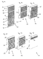
- FIGS 1a to 1f show an embodiment of an inventive Winding device in different Aufrolllagen, whereby the different Cover conditions can be clarified, which can be realized with the winding device are.
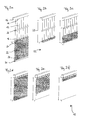
- FIGS. 2 a to 2 f show the reeling positions of FIG. 1 equivalent to those of FIG alternative embodiment of the present invention.
- Fig. 3 shows a further alternative embodiment of the present invention Invention.
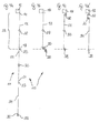
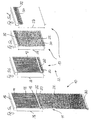
- Figures 4a to 4d show schematic side views of another alternative embodiment of the winding device according to the invention, consisting of three joined surface webs is formed.
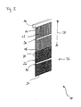
- Figures 5a to 5d show schematic perspective views of another alternative embodiment of the winding device according to the invention, consisting of two formed surface webs is formed, each having different lengths are.
- Winding device 10 comprises in the illustrated embodiment, a cover 11, which consists of two differently designed surface webs 12, 22nd composed.
- a first surface track 12 is provided with an upper longitudinal side 14 rigidly anchored to a bracket 16.
- a lower longitudinal side 18 of the first Surface web 12 is provided with an upper longitudinal side 20 of a second surface web 22 whose lower longitudinal side 24 hang loosely down or through here not shown guide elements can be guided laterally.
- a first winding element 26 Approximately in the middle between upper longitudinal side 14 and lower longitudinal side 18 of the first surface track 12 is a first winding element 26, which by a rotation for a two-ply winding the first tissue or surface web 12 can provide.
- the second surface web 22 is pulled upwards, so that a to be covered surface 28 with the second surface web 22 is variably covered.
- the first surface web 12 is considered loose woven net grid formed while the second surface web 22 denser woven or from a closed structure - for example, a foil or tarpaulin - can exist.
- a second winding member 30 is disposed, which is applied by an externally applied Rotational movement for a single-layer curling of the second surface web 22 of below can care.
- FIG. 1a The schematic perspective view of Fig. 1a shows the winding device 10 in the fully unrolled state. Both surface webs 12 and 22 are here shown unrolled to their respective full length.
- the cover 11 can basically any number of such surface webs, each preferred different properties in terms of their permeability to air, light, heat, Sound, etc., exist and thus be almost arbitrarily long.
- FIG Winding device 10 in practice normally no application, since the Covering 11 is significantly longer than the area to be covered 28.
- a corresponding winding of the cover 11 on the winding elements 26, 30 is the length of the cover 11 to the size of the surface to be covered 28th customized.
- the area to be covered 28 may, for example, a building opening, a Building side wall o. The like. Be.
- the area to be covered 28 can basically but also a variable opening or closing opening cross-section be within a building, a hall or any other room using the cover 11 with respect to its permeability to light, air, sound, Heat, UV radiation o. The like. Can be variably modified.
- the surface 28 can be variable completely with the first surface track 12 (Fig. 1b) or completely with the second surface track 22 (FIG. 1d) or with the first and the second Surface web in any proportions (Fig. 1c) imposed or alternatively opened and finally fully exposed ( Figures 1e and 1f).
- Fig. 1b illustrates a first operating position of the invention Winding device 10.
- the second surface web 22 is here almost completely rolled up on its lower longitudinal side 24 winding element 30 rolled up.
- winding element 30 rolled up.
- it can also be a lying below the surface to be covered 28, also expose the surface 32 to be covered.
- the first or upper surface to be covered 28 is imposed in the illustrated operating position of the first surface track 12, since this is in the fully unrolled state. That within the range the upper surface web 12 arranged winding element 26 is in this position completely free.
- Fig. 1c illustrates a partially rolled first surface web 12, in the the first winding element 26 is rotated relative to the illustration of FIG. 1b, so that the first surface web 12 is partially wound on this and thus shortened.
- the second winding element 30 are rotated in such a way that the second Surface web 22 is partially unrolled. This can, for example, by holding the lower winding element 30 happen.
- the lower winding element 30 but also an independent rotary motion by its own drive To run.
- the second surface track 22 is tracked in this way to the To be covered area 28 partially obscure.
- Execution of the two rotational movements remains in this adjustment to covering surface 28 at all times with the two surface sheets 12, 22nd covered, it only changes the relationship in which the two Surface webs 12, 22 contribute to cover the surface 28.
- this ratio is shifted to the second surface web 22 out.
- the first surface web 12 is completely rolled up onto the first winding element 26, whereby the surface to be covered 28 largely from the second fabric web 22nd is covered.
- the second winding element 30 can hereby almost completely rolled out be.
- Figures 1e and 1f show how by turning the second Winding element 30, a rolling up of the second, lower surface web 22 and thus an exposure of the surface 28 takes place from below.
- Fig. 1f is the fully open Position of the winding device 10 is reached, in which the surface 28 is largely uncovered is.
- FIGS. 1b to 1d can also be understood as meaning that the second winding element 30 in its height in the region at the lower edge of the covering surface 28 is rotatably fixed and not according to the figures 1a, 1e and 1f can be adjusted in height.
- the one to be covered Surface 28 are not completely exposed, but only optionally with the first Surface 12 (Fig. 1b), with the second surface 22 (Fig. 1d) or in any Division ratio with both surfaces 12, 22 (Fig. 1c) are covered.
- the second Winder element 30 can passively rotate here, since it is mounted laterally. This sets However, foresee that for a reverse rotation of the second winding element 30th what is, for example, by means of a suitable return spring, a suitable Other clamping device o. The like. Can be achieved.
- FIGS. 1a to 1f Winding device 10 The schematic perspective views of Figures 2a to 2f illustrate again the corresponding operating positions shown in FIGS. 1a to 1f Winding device 10.
- the upper Surface track 12 of several, juxtaposed ropes, cords or bands, which are analogous to the mesh fabric in Figures 1a to 1f for varying the Covering be rolled onto the corresponding winding element 26.
- FIG. 3 illustrates another Variant in which the second winding element 30 is not on the lower longitudinal side 24 of second surface track 22, but is disposed approximately in the middle thereof, so that Also, the second winding element 30 for a double-layer winding the corresponding fabric web 22 can provide, as in the first fabric web 12 according to the figures 1a to 1f and 2a to 2f is the case.
- the lower Long side 24 of the second surface 22 optionally also at the bottom of the zu Covering surface 28 and the opening may be fixed, for example.
- a rigid Anchoring In this case, no complete release of the opening is possible, but only an optional or partial covering with the first surface 12th or the second surface 22.
- Figures 4a to 4d show schematic side views of another alternative embodiment of the winding device 10 according to the invention, whose Covering element 11 of three joined surface webs 12, 22 and 34th is formed.
- FIG. 4a illustrates the cover 11 in the fully unrolled state, in which the first surface 12 with its upper longitudinal side 14 rigidly on the holder 16 is anchored.
- the lower longitudinal side 18 of the first surface 12 is connected to the upper Long side 20 of the second surface 22 is connected, the lower longitudinal side 24th in turn connected to an upper longitudinal side 35 of a third surface 34.
- the first winding element 26 is arranged.
- the second winding element 30 is arranged at the lower longitudinal side 36 of the third Surface 34.
- FIG. 4b illustrates that with the first Surface 12 covered surface 28.
- the second surface 22 and the third surface 34 are here on the second winding element 30 (double-layered) or on the third Winding element 38 (single layer) rolled up.
- Second and third winding element 30 and 38 are located near the lower edge of the surface 28 to be covered.
- FIG. 4c illustrates that with the second Surface 22 covered surface 28.
- the first surface 12 and the third surface 34 are here on the first winding element 26 (double-layered) or on the third Winding element 38 (single layer) rolled up.
- the first winding element 26 is located in this case near the upper edge of the surface 28 to be covered.
- the third Winding element 38 is in this case close to the lower edge of the to be covered Area 28.
- FIG. 4d illustrates that with the third Surface 34 covered surface 28.
- the first surface 12 and the second surface 22 are here on the first winding element 26 (double-layered) or on the second Winding element 30 (double-layered) rolled up.
- First and second winding element 26 and 30 are here near the upper edge of the surface to be covered 28.
- Das third winding element 38 is in this case close to the lower edge of the covering area 28.
- the winding device 10 shown in FIGS. 4 a to 4 d can, for example, be used for variable formation of heat, sound and / or light at least partially shielding partition in a production hall o.
- the like. Serve.
- the first surface 12 may be a UV light impermeable layer which allows Welding work is carried out in one area of the production hall without that the immediately adjacent areas are affected.
- the second Surface 22 may, for example, a sound largely impermeable or noise be insulating layer, which makes it possible to adjacent production areas to shield from noise-intensive work.
- the third surface 34 may, for example, a Heat insulating layer that can allow it in part of the hall Charging or manufacturing work to be carried out with open external doors, without In this case, adjacent to the area exposed to the weather.
- Figures 5a to 5d show schematic perspective views of another alternative embodiment of the winding device 10 according to the invention, which two adjoining surface sheets 12 and 22 is formed, respectively are different lengths.
- the schematic representation of Fig. 5a illustrates the Winding device 10 with unrolled cover 11 whose uppermost arranged first surface 12 with its upper longitudinal side 14 by means of rigid Attachment is anchored to the bracket 16.
- the area to be covered 28 corresponds in height about the length of the first surface 12 to its lower Longitudinal side 18, to which the second surface 22 connects.
- the first winding element 26 is located in this variant of Winding device 10 between the lower longitudinal side 18 of the first surface 12th and the upper longitudinal side 20 of the second surface 22, so that when turning the first winding element 26 is a two-ply winding of the first and second Surfaces 12 and 22 are superimposed (see Fig. 5c).
- the second winding element 30 is located on the lower longitudinal side 24 of the second surface 22, so that these are wound in a single layer during a rotation of the second winding element 30 can (see Fig. 5b).
- Winding element 30 may be a variable covering of the surface 28 with the second or the first surface 22 or 12 take place.
- the surface 28 of the first surface 12th covered ( Figure 5b).
- first winding element 26 When placed at the top of the surface 28 first winding element 26, surface 28 is covered by second surface 22 (FIG. 5c).
- second surface 22 When placed at the top of the surface 28 first winding element 26, surface 28 is covered by second surface 22 (FIG. 5c).
- intermediates between these two cover variants are by appropriate rotation of the first winding element 26 possible, in which case in each case the second winding element 30 is rotated, since when turning the first winding element 26, the second Surface 22 is unrolled from the second winding element 30 and rolled up on this.
- the surface 28 is largely released by the first rolled up Winding element 26 and the second winding element 30 is rolled up (Fig. 5d).
- the preferably flexible connections of the individual surfaces 12, 22 and / or 34 or tarpaulins, fabric webs or the like. at their respective adjacent Long sides can also be done in different ways.
- the surfaces can For example, welded together, riveted, sewn or otherwise unsolvable be connected to each other.
- detachable connections can also be used be meaningful, for example.
- the Connections can also be made through lockable and / or openable Connecting rings or be produced by means of connecting cords or bands, the through corresponding openings near the adjacent longitudinal sides of the Surfaces are looped or braided.
- there are many more Types of compounds conceivable as equivalents of each of the present invention are included.
Landscapes
- Engineering & Computer Science (AREA)
- Structural Engineering (AREA)
- Architecture (AREA)
- Civil Engineering (AREA)
- Operating, Guiding And Securing Of Roll- Type Closing Members (AREA)
- Winding Of Webs (AREA)
- Rolls And Other Rotary Bodies (AREA)
- Massaging Devices (AREA)
- Blinds (AREA)
Abstract
Description
Die vorliegende Erfindung betrifft eine Wickelvorrichtung, insbesondere eine Wickeljalousie mit den Merkmalen des unabhängigen Anspruchs.The present invention relates to a winding device, in particular a Winding blind with the features of the independent claim.
Anwendungsbereiche für derartige Wickeljalousien sind vielfältig. So kommen sie bspw. zur variablen Abschirmung von Räumen, zur variablen Belüftung und/oder Abschattung von Tierställen, von Gewächshäusern oder dergleichen zum Einsatz. Üblicherweise weisen derartige Abschirmvorrichtungen Rollsysteme mit variabel aufund abrollbaren Gewebebahnen auf, um eine gewünschte Abschattung bzw. Abschirmung der Gebäude- oder Wandöffnung zu ermöglichen.Areas of application for such winding blinds are diverse. So come For example, for variable shielding of rooms, for variable ventilation and / or Shading of animal houses, greenhouses or the like for use. Typically, such shielding devices have variable pitch roll systems unrolled fabric webs to a desired shading or To shield the building or wall opening.
Herkömmliche Jalousieeinrichtungen, bei denen eine drehbare Wickelrolle oberhalb einer zu bedeckenden Öffnung angeordnet ist, ermöglichen lediglich ein Aufund Abrollen der Gewebebahn auf der Wickelrolle und damit eine variable Öffnung nach oben hin. Derartige Jalousieeinrichtungen dienen bspw. zur Beschattung von Fensteröffnungen in Häusern und Wohnungen. Daneben gibt es Jalousieeinrichtungen, bei denen eine obere Längsseite einer Gewebebahn starr befestigt und eine untere Längsseite mit einer höhenverstellbaren Wickelrolle versehen ist. Derartige Jalousieeinrichtungen werden bspw. bei Gewächshäusern eingesetzt. Die Gewebebahn kann bei derartigen herkömmlichen Wickelvorrichtungen lediglich von unten nach oben geöffnet werden, was für manche Anwendungsfälle ungünstig ist.Conventional Venetian blinds, where a rotatable winding roll is arranged above an opening to be covered, allow only a Aufund Unrolling the fabric web on the winding roll and thus a variable opening upwards. Such Venetian blinds serve, for example, for shading Window openings in houses and apartments. There are also blinds, in which an upper longitudinal side of a fabric web rigidly fixed and a lower Long side is provided with a height-adjustable winding roll. such Venetian blinds are used, for example, in greenhouses. The Fabric web can in such conventional winding devices of only be opened down to the top, which is unfavorable for some applications.
So ist bspw. in Tierställen eine ständige Bedeckung des unteren Bereichs der Öffnung bei gleichzeitig variabel luft- und/oder lichtdurchlässig gestaltbarem oberem Bereich erwünscht. Aus diesem Grund sind variablere Abschirmvorrichtungen bekannt geworden, bei denen die zuvor starr oberhalb der zu bedeckenden Öffnung angeordnete Wickelrolle höhenverstellbar ausgeführt ist. Eine derartige Abschirmvorrichtung, bei der eine obere Wickelrolle bzw. eine obere Fixierung einer Gewebebahn mittels eines Seilzugsystems in der Höhe verstellbar gemacht ist, ist bspw. aus der DE 103 36 944 A1 bekannt. Die obere Seilführung ist hierbei allerdings relativ aufwändig, schwer zu justieren und im länger andauernden Betrieb störungsanfällig. For example, in animal stalls a permanent covering of the lower area of the Opening at the same time variably air- and / or translucent formable upper Area desired. For this reason, more variable shielding devices are known become, with which previously rigidly above the opening to be covered arranged winding roller is designed height adjustable. Such Shielding device, in which an upper winding roll or an upper fixation of a Fabric web is made adjustable by means of a cable system in height is For example, from DE 103 36 944 A1 known. The upper cable guide is here, however relatively complex, difficult to adjust and in longer lasting operation trouble-prone.
Ein anderes System zur variablen Belüftung und/oder Beschattung von Gebäuden oder Räumen ist aus der DE 202 14 076 U1 bekannt. Diese Vorrichtung umfasst ein oberes und ein unteres Rollsystem zum Auf- und Abrollen eines Schirms, so dass unterschiedliche Gewebearten wahlweise auf der oberen oder unteren Wickelrolle aufgerollt werden können. Hierdurch wird der Raum bspw. mit einer dichteren Gewebeart beschattet oder mittels einer sehr weitmaschig gewebten Gewebeart luft- und lichtdurchlässig gemacht. Die beiden Wickelelemente sind jeweils starr oberhalb und unterhalb der Raumöffnung verankert. Eine derartige Vorrichtung kann sich nicht über eine beliebige Breite erstrecken, da die Unterschiede in den Durchmessern der oberen und unteren Rolle jederzeit mittels einer Aufspannvorrichtung ausgeglichen werden müssen und die Lagerung der oberen Wickelrolle bei sehr breiten und somit schweren Abschirmbahnen problematisch ist. Die Verwendung der derartigen Vorrichtung zur Abdeckung eines sehr breiten Bereiches erfordert somit ein Aneinanderreihen mehrerer derartiger Vorrichtungen.Another system for variable ventilation and / or shading of Buildings or rooms is known from DE 202 14 076 U1. This device comprises an upper and a lower roll system for winding and unrolling a screen, so that different tissue types are optional on the top or bottom Wrapping roll can be rolled up. As a result, the room is, for example, with a Tight fabric type shaded or by means of a very weitmaschig woven Fabric type made air and translucent. The two winding elements are each rigidly anchored above and below the room opening. Such a device can not extend over any width, because the differences in the Diameters of the upper and lower roll at any time by means of a Clamping device must be balanced and the storage of the upper Winding roll is problematic for very wide and thus heavy shielding. The use of such a device to cover a very wide Bereiches thus requires a juxtaposition of several such devices.
Eine ähnlich geartete Rollovorrichtung mit einer ersten und einer abweichend beschaffenen zweiten Materialbahn, die jeweils um eine Wickelachse wickelbar sind, und die jeweils mit einem ersten Ende im Bereich ihrer Wickelachse an einem Halter befestigt sind, ist weiterhin aus der DE 92 10 938 U1 bekannt. Die erste und die zweite Materialbahn sind an ihrem freien zweiten Ende miteinander fest verbunden und die Halter sind relativ zueinander aufeinander zu bzw. voneinander weg bewegbar, wobei bei diesen Bewegungen die beiden Materialbahnen auf- bzw. abwickelbar sind.A similar kind of roller blind device with a first and a different provided second material web, which are each wound around a winding axis, and each with a first end in the region of its winding axis on a holder are fixed, is further known from DE 92 10 938 U1. The first and the second Material web are firmly connected together at their free second end and the Holders are movable relative to each other toward or away from each other, wherein in these movements, the two webs are up or unwound.
Ein Ziel der vorliegenden Erfindung besteht darin, eine Wickelvorrichtung zum variablen Bedecken von Flächen, bspw. Öffnungen in Räumen oder Gebäuden, mit Abdeckelementen unterschiedlicher Beschaffenheiten bzw. Freistellen dieser Flächen zur Verfügung zu stellen, die einfach aufgebaut und betätigbar ist und die sich auch für große Flächen eignet.An object of the present invention is to provide a winding device for variable covering of surfaces, for example openings in rooms or buildings, with Covering elements of different textures or cropping these surfaces which is simple to set up and operate and which is also suitable for large areas is suitable.
Dieses Ziel der Erfindung wird mit dem Gegenstand des unabhängigen Anspruchs erreicht. Merkmale vorteilhafter Weiterbildungen der Erfindung ergeben sich aus den abhängigen Ansprüchen.This object of the invention is with the subject matter of the independent Achieved. Features of advantageous developments of the invention will become apparent from the dependent claims.
Die erfindungsgemäße Wickelvorrichtung mit den Merkmalen des unabhängigen Anspruchs ermöglicht eine variable Bedeckung von Flächen, bspw. Öffnungen in Räumen oder Gebäuden, mit Abdeckelementen, wobei ein Abdeckelement wenigstens zwei oder mehrere unterschiedlich beschaffene, aneinander grenzende Oberflächenbahnen umfasst und wobei im Zusammenhang mit der Anordnung von zwei oder mehreren Wickelelementen die zu bedeckende Fläche nach Erfordernis konstant mit jeweils wenigstens einer Oberflächenbahn einer wählbaren Beschaffenheit bedeckt bleiben kann. Gemäß der vorliegenden Erfindung ist im Bereich von wenigstens zwei Oberflächenbahnen unterschiedlicher Beschaffenheiten je wenigstens ein drehbares Wickelelement angeordnet, wobei die jeweiligen Oberflächenbahnen jeweils variabel auf die jeweiligen drehbaren Wickelelemente aufrollbar sind und eine zuoberst angeordnete Oberflächenbahn an einer Oberkante eine starre Befestigung aufweist.The winding device according to the invention with the features of independent claim allows variable coverage of areas, eg. Openings in rooms or buildings, with cover elements, where a Cover element at least two or more differently procured, includes adjacent surface webs and being associated with the arrangement of two or more winding elements, the area to be covered as required, each with at least one surface track of a constant selectable condition can remain covered. According to the present invention is different in the range of at least two surface webs Textures each arranged at least one rotatable winding element, wherein the respective surface paths each variable to the respective rotatable Winding elements are rolled up and an uppermost arranged surface web an upper edge has a rigid attachment.
Mit der erfindungsgemäßen Wickelvorrichtung ist es möglich, eine zu bedeckende oder freizugebende Öffnung in einem Gehäuse, einem Gebäude, einem Stall, einem Gewächshaus oder dergleichen variabel zu öffnen oder zu schließen bzw. zu beschatten oder weitgehend freizugeben. Damit stellt die erfindungsgemäße Wickelvorrichtung eine vorteilhafte Weiterentwicklung dar, da die derzeit bekannten Jalousievorrichtungen mit oberer starrer Befestigung ein variables Belüften einer oberen Öffnung mit gleichzeitiger Abdeckung eines unteren Bereichs der Öffnung nicht zulassen.With the winding device according to the invention, it is possible to one Covering or releasing opening in a housing, a building, a Stable, a greenhouse or the like to open or close variably to shade or largely release. Thus, the inventive Winding device is an advantageous development, since the currently known Venetian blind devices with upper rigid attachment variable ventilation of one upper opening with simultaneous coverage of a lower area of the opening is not allow.
Neben den bereits genannten gibt es zahlreiche weitere Anwendungsgebiete für die erfindungsgemäße Wickelvorrichtung. So können derartige Wickelvorrichtungen als mobile Trennwände im Außen- und/oder Innenbereich eingesetzt werden, bspw. als mobile Trennwände in Fertigungshallen, die den unterschiedlichsten Anforderungen genügen können. So können damit bspw. variabel handhabbare Brandschutzwände, Schallschutzwände und/oder Lärmschutzwände realisiert werden, die nur im Bedarfsfall aus ihrer oberen Aufhängung gezogen und bei Nichtgebrauch wieder eingerollt werden können. An manchen Fertigungsstätten sind UV-Schutzwände notwendig, bspw. zur Abschirmung von Schweißarbeitsplätzen. Auch hier kann die erfindungsgemäße Wickelvorrichtung vorteilhaft eingesetzt werden. Die genannten Anwendungsfälle oder Teile davon sind mittels jeweils einer Wickelvorrichtung problemlos realisierbar, da die unterschiedlichen Gewebe- bzw. Oberflächenbahnen den jeweiligen Einsatzzwecken angepasst sein und entsprechend ausgerollt werden können. In addition to those already mentioned, there are numerous other applications for the winding device according to the invention. Thus, such winding devices be used as mobile partitions in the outer and / or interior, for example. As mobile partitions in production halls, which meet the most diverse requirements can suffice. Thus, for example, variably manageable fire protection walls, Soundproof walls and / or noise barriers are realized only in the If necessary, pulled out of their upper suspension and when not in use again can be rolled. In some factories there are UV barriers necessary, for example for shielding welding workplaces. Again, the winding device according to the invention can be used advantageously. The mentioned Use cases or parts thereof are each by means of a winding device easily realizable, since the different tissue or surface webs be adapted to the respective purposes and be rolled out accordingly can.
Wenn im vorliegenden Zusammenhang die Begriffe "Oberflächenbahn" bzw. "Oberflächen unterschiedlicher Beschaffenheiten" verwendet werden, so sind damit grundsätzlich Abschnitte von Abschirmelementen gemeint und umfasst, die wahlweise aus unterschiedlichsten Gewebearten wie Netzgittergewebe bzw. herkömmlichen mehr oder weniger dicht gewebten Stoffen, aus nebeneinander verlaufenden Schnüren, Seilen oder flachen Bändern, oder auch aus geschlossenen Oberflächen wie bspw. Kunststoff- oder Kunstfaserfolien bzw. -planen bestehen können. Die derart gestalteten Abschnitte können jeweils aus Natur- und/oder Kunstfasern bzw. -folien o. dgl. gefertigt sein und weisen bevorzugt jeweils unterschiedliche Eigenschaften bezüglich ihrer Durchlässigkeiten bspw. für Licht, Luft, Wasser, aber auch für Staub oder andere Luftpartikel, Insekten etc. auf.If, in the present context, the terms "surface web" or "Surfaces of different textures" are used, so are with it basically includes sections of shielding elements and includes, which optionally from different types of fabric such as net mesh or conventional more or less densely woven fabrics, of strings running side by side, Ropes or flat bands, or even from closed surfaces such as. Plastic or synthetic fiber films or tarpaulins can exist. The like designed sections can each be made of natural and / or synthetic fibers or foils o. Like. Be manufactured and preferably each have different properties in terms of their permeabilities, for example, for light, air, water, but also for dust or other air particles, insects, etc.
Wenn von unterschiedlichen Beschaffenheiten der Oberflächen die Rede ist, so können damit grundsätzlich neben den erwähnten Eigenschaften der Licht- und Luftdurch- bzw. -undurchlässigkeit auch andere physikalische und/oder chemische Eigenschaften gemeint sein, bspw. eine - oben bereits erwähnte - zumindest teilweise Undurchlässigkeit für UV-Licht, für Schall o. dgl. Je nach gewählter Ausgestaltung kann die Wickelvorrichtung somit den vielfältigsten Einsatzzwecken genügen.When talking about different textures of the surfaces, so can thus in addition to the mentioned properties of the light and Air impermeability and other physical and / or chemical Be meant properties, for example, one - already mentioned above - at least partially Impermeability to UV light, for sound o. The like. Depending on the selected configuration the winding device thus satisfy the most varied uses.
Wenn auch im Zusammenhang mit der vorliegenden Beschreibung sowie des nachfolgenden Ausführungsbeispiels meist von einem sich in vertikaler Richtung erstreckenden Abdeckelement bzw. von senkrecht nach unten hängenden Oberflächen, Planen o.ä. die Rede ist, so ist eine solche Anordnung keineswegs zwingend. Es versteht sich für den Fachmann von selbst, dass auch eine schräge oder horizontale Anordnung der erfindungsgemäßen Wickelvorrichtung möglich ist und sinnvoll sein kann, wobei hier ggf. für eine entsprechende Straffung des aufwickelbaren Abdeckelementes zu sorgen ist. Insbesondere bei den Varianten, bei denen sowohl eine obere Kante als auch eine untere Kante jeweils starr eingespannt ist, können geeignete seitliche Führungen bzw. Spannelemente genügen, um einen unerwünschten Durchhang zu verhindern.Although in connection with the present description and the following embodiment, usually from a in the vertical direction extending cover or hanging from vertical downwards Surfaces, tarpaulins or similar there is no question of such an arrangement mandatory. It goes without saying for the expert that even an oblique or horizontal arrangement of the winding device according to the invention is possible and can be useful, where appropriate, if necessary for a corresponding streamlining of the aufwickelbaren Covering is to ensure. Especially in the variants where both an upper edge and a lower edge is respectively rigidly clamped can suitable lateral guides or clamping elements are sufficient to a prevent unwanted slack.
Gemäß einer bevorzugten Ausgestaltung der vorliegenden Erfindung erstreckt sich ein derartiger Abschnitt eines Abschirmelementes über die gesamte Breite bzw. Länge der Wickelvorrichtung in Längserstreckungsrichtung der Wickelelemente und entspricht in seiner Länge bzw. Breite ungefähr der Länge bzw. Breite der abzudeckenden Fläche, so dass ein einzelner derartiger Abschnitt bei entsprechender Wicklung der Wickelvorrichtung die gesamte abzudeckende Fläche bedecken kann. Eine typische Breite einer erfindungsgemäßen Wickelvorrichtung kann bspw. bis zu 20 Meter oder mehr betragen. Je nach Bedarf sind jedoch auch wesentlich größere Breiten variabel abdeckbar. Für den Fachmann versteht sich von selbst, dass sehr breite abzudeckende Flächen wahlweise auch mit in mehrere Abschnitte bzw. Segmente unterteilten Wickelvorrichtungen variabel bedeckt werden können, bei denen wahlweise mehrere Wickelvorrichtungen parallel angeordnet sind, oder bei denen lediglich die Oberflächen segmentiert und jeweils auf gemeinsamen Wickelelementen aufrollbar sind.According to a preferred embodiment of the present invention extends Such a portion of a shielding over the entire width or Length of the winding device in the longitudinal direction of the winding elements and corresponds in its length or width approximately the length or width of the Covered area, so that a single such section at appropriate Winding the winding device can cover the entire area to be covered. A typical width of a winding device according to the invention can, for example, up to 20 Meters or more. Depending on the need, however, are also much larger Widths variably coverable. For the expert it goes without saying that very much Wide to be covered surfaces optionally also in several sections or Segments subdivided winding devices can be covered variably, at which optionally a plurality of winding devices are arranged in parallel, or at which only the surfaces segmented and each on common Winding elements are rolled up.
Beliebig viele derartige Abschnitte sind jeweils an ihren Längskanten fest miteinander verbunden, so dass das gesamte Abschirmelement beliebig lang sein kann. Erfindungsgemäß ist immer ein so großer Anteil des Abschirmelements auf die wenigstens zwei Wickelelemente aufgerollt, dass die Länge des freiliegenden, die Fläche bedeckenden Anteils des Abschirmelements maximal der Höhe bzw. Breite der zu bedeckenden Fläche entspricht.Any number of such sections are each fixed at their longitudinal edges connected together, so that the entire shielding be arbitrarily long can. According to the invention is always such a large proportion of the shielding on the rolled up at least two winding elements that the length of the exposed, the Surface covering portion of the shielding member maximum of the height or width of the corresponds to the area to be covered.
Innerhalb von wenigstens zwei derartigen Abschnitten des Abschirmelementes ist erfindungsgemäß jeweils wenigstens ein Wickelelement angeordnet. Die Wickelelemente der erfindungsgemäßen Wickelvorrichtung sind insbesondere in einem mittleren Bereich der ihnen jeweils zugeordneten Oberflächenbahn angeordnet und an dieser Stelle fest mit der entsprechenden Oberflächenbahn verbunden, so dass bei einer Drehung des entsprechenden Wickelelements ein von ihrer Mitte ausgehendes doppellagiges Wickeln der jeweiligen Oberflächenbahn um das Wickelelement herum erfolgt. Alternativ können auch zwei oder mehrere Wickelelemente innerhalb eines Abschnitts des Abschirmelements angeordnet sein. Diese müssen hierbei jeweils so über den Bereich der Oberflächenbahn verteilt sein, dass sie sich während des Wickelvorgangs nicht gegenseitig behindern. Bspw. muss beim Einsatz von zwei Wickelelementen pro Oberflächenbahn das erste etwa im oberen Viertel und das zweite im unteren Viertel der Oberflächenbahn angeordnet sein.Within at least two such sections of the shielding element According to the invention, at least one winding element is arranged in each case. The Winding elements of the winding device according to the invention are in particular in one Arranged middle region of their respective associated surface track and at this place firmly connected to the corresponding surface track, so that at a rotation of the corresponding winding element emanating from its center two-ply winding of the respective surface web around the winding element around he follows. Alternatively, two or more winding elements within a Be arranged portion of the shielding. These must be in each case so be distributed over the area of the surface track that they are during the Winding process does not interfere with each other. For example. must when using two Wickelelementen per surface web the first about in the upper quarter and the second be arranged in the lower fourth of the surface web.
Ein im Bereich der zuunterst angeordneten Oberflächenbahn angeordnetes Wickelelement kann wahlweise am unteren Ende der Oberflächenbahn angeordnet sein, so dass zumindest die zuunterst liegende Oberflächenbahn von einer Unterkante ausgehend einlagig aufgewickelt werden kann. Durch das Aufwickeln der untersten Oberflächenbahn kann ein Freistellen der Fläche, bspw. der Gebäude- oder Raumöffnung, von unten her erfolgen. Weiterhin ist es alternativ möglich, bei einer bereits aufgerollten unteren Oberfläche nur das obere Wickelelement aufzurollen und gleichzeitig das untere Wickelelement in seiner Höhe zu fixieren. Ggf. kann hierzu das untere Wickelelement drehbar verankert sein, so dass die zu bedeckende Fläche nicht vollständig freigelegt werden, sondern nur wahlweise mit einer von mehreren Oberflächen bedeckt werden kann.A arranged in the region of the lowest arranged surface web Winding element can optionally be arranged at the lower end of the surface web be, so that at least the lowermost surface web of a lower edge can be wound single-layer starting. By winding the bottom one Surface track can be an exemption of the area, eg. The building or Room opening, done from below. Furthermore, it is alternatively possible with a already rolled up lower surface to roll up only the upper winding element and at the same time to fix the lower winding element in its height. Possibly. can do this lower winding element to be rotatably anchored, so that the surface to be covered not completely exposed, but only with one of several optional Surfaces can be covered.
Gemäß einem vorteilhaften Aspekt der vorliegenden Erfindung sind die Wickelelemente in Bewegungsrichtung des Abdeckelements nicht fest verankert, sondern führen während des Wickelvorgangs eine in Bewegungsrichtung des Abdeckelements gerichtete Bewegung aus, die sich aus der Verkürzung bzw. Verlängerung der freiliegenden Fläche der jeweiligen Oberflächenbahn ergibt. Bei einer hängenden Ausführungsform der vorliegenden Erfindung bewegt sich das Wickelelement während des Aufwickelvorgangs nach oben und während des Abwickelvorgangs nach unten, sofern nicht ein weiteres, darüber liegendes Wickelelement einen Wickelvorgang ausführt, der die absolute Auf- oder Abwärtsbewegung des unteren Wickelelementes ausgleicht. Die Wickelelemente können - wie das Abdeckelement - frei im Raum hängen. Alternativ können sie mit Seitenbereichen, die seitlich über die Abdeckelemente hinausragen können, in Führungselemente, bspw. Führungsschienen, eingreifen. Wie bereits zuvor erwähnt, kann jedoch wahlweise eines oder mehrere der Wickelelemente drehbar und in vorgegebener Höhe gelagert sein, so dass keine vollständiges Freigabe der zu bedeckenden Öffnung möglich ist, sondern nur eine wahlweise Bedeckung mit einer bzw. eine teilweise Bedeckung mit mehreren der vorhandenen Oberflächen.According to an advantageous aspect of the present invention, the Winding elements not firmly anchored in the direction of movement of the cover, but lead during the winding process in the direction of movement of the Covering directed movement, resulting from the shortening or Extension of the exposed surface of the respective surface track results. At a hanging embodiment of the present invention moves Wrapping element during the winding up and during the Unwinding down, if not another, overlying Winding performs a winding process, the absolute up or Downward movement of the lower winding element compensates. The winding elements can - like the cover - hang freely in the room. Alternatively you can with Side areas that can protrude laterally beyond the cover, in Guide elements, eg. Guide rails, engage. As mentioned earlier, However, optionally one or more of the winding elements rotatable and in be stored predetermined height, so that no complete release of the Covering opening is possible, but only an optional covering with a or a partial covering with several of the existing surfaces.
Der Antrieb der Wickelelemente - dies sind insbesondere bekannte Wickelrohre, Wickelstangen oder dergleichen - kann wahlweise manuell, elektromotorisch oder auf sonstige Weise erfolgen. Bspw. können Motorumdrehungen mittels Kardanwellen, Zahnriemen- oder Keilriemenmechanismen auf die Wickelelemente übertragen werden, oder Motoren können jeweils innerhalb der Wickelelemente angeordnet sein. Derartige Wickelantriebe sind bekannt und nicht Teil der vorliegenden Erfindung. Sie werden daher an dieser Stelle nicht näher erläutert. Beispiele für Antriebe von Wickelelementen, wie sie im Rahmen der vorliegenden Erfindung verwendet werden können, finden sich unter anderem in der DE 202 14 076 U1, in der EP 0 567 030 A2, in der DE 203 20 335 U1 oder in der DE 103 36 944 A1. The drive of the winding elements - these are in particular known Winding tubes, winding rods or the like - can be manually, carried out by electric motor or otherwise. For example. can engine revolutions By means of cardan shafts, toothed belt or V-belt mechanisms on the Winding elements are transferred, or motors can each within the Be arranged winding elements. Such winding drives are known and not part of the present invention. They are therefore not explained in detail at this point. Examples of drives of winding elements, as described in the present The invention can be used, inter alia, in DE 202 14 076 U1, in EP 0 567 030 A2, in DE 203 20 335 U1 or in DE 103 36 944 A1.
Nicht alle Oberflächenbahnen, die das Abdeckelement bilden, müssen ein Wickelelement aufweisen. Es ist ebenso möglich, dass eine Oberflächenbahn ohne Wickelelement an dem Abdeckelement beteiligt ist, welches dann weniger variabel einsetzbar ist. Bspw. ist es denkbar, dass eine Grenze zwischen zwei unterschiedlich gearteten Oberflächenbahnen mittels eines Einsatzes aus einer weiteren, wiederum anders beschaffenen Oberflächenbahn gestaltet ist. Auch die zuoberst angeordnete Oberflächenbahn kann bspw. ohne Wickelelement ausgeführt sein, so dass sie als feststehende obere Abdeckung jederzeit vorhanden ist.Not all surface webs that make up the cover need to Have winding element. It is also possible that a surface web without Winding element is involved in the cover, which then less variable can be used. For example. It is conceivable that a border between two different type surface webs by means of an insert from another, in turn differently designed surface track is designed. Even the topmost arranged Surface web can be performed, for example, without winding element, so that they as fixed top cover is always available.
Nicht alle Oberflächenbahnen müssen jeweils die selbe Länge aufweisen. Grundsätzlich sind nahezu beliebige unterschiedliche oder gleiche Längen möglich. Eine zuoberst angeordnete Oberflächenbahn kann bspw. am unteren Ende ein Wickelelement aufweisen, so dass bei dessen Drehung ein doppellagiges Aufwickeln der ersten Oberflächenbahn sowie einer sich daran anschließenden zweiten Oberflächenbahn erfolgt. Die zweite Oberflächenbahn ist vorzugsweise länger als die erste Bahn, bspw. doppelt so lang wie diese. Am unteren Ende kann die zweite Oberflächenbahn ein weiteres Wickelelement aufweisen, so dass eine variable Abdeckung einer zu bedeckenden Fläche mittels der ersten und/oder der zweiten Oberflächenbahn bzw. deren Freilegung bei vollständig aufgerollter erster und zweiter Bahn ermöglicht ist.Not all surface webs must each have the same length. Basically, almost any different or equal lengths are possible. An uppermost surface web can, for example, at the lower end a Have winding element, so that when it turns a double-layer winding the first surface track and a subsequent second Surface track takes place. The second surface sheet is preferably longer than the second surface sheet first track, for example, twice as long as this. At the bottom, the second Surface web have another winding element, so that a variable Covering a surface to be covered by means of the first and / or the second Surface web or its exposure at fully rolled up first and second Rail is possible.
Die zuoberst angeordnete Oberflächenbahn weist erfindungsgemäß an einer Oberkante eine starre Befestigung auf. Bspw. kann die Oberkante des obersten Abschnitts des Abschirmelements starr an einem festen Gebäudeteil, bspw. an einer Außenwand befestigt sein, so dass das obere Ende der Wickelvorrichtung in fester Position verankert ist. Die Befestigung kann alternativ durch die Verbindung mit einer starren Halteeinrichtung, bspw. einer Schiene erfolgen. Diese Schiene kann wiederum fest an einem Gebäudeteil angebracht sein. Alternativ kann sie auch mit einer Hebevorrichtung kombiniert sein, die für ein gleichmäßiges Heben oder Senken der Schiene sorgen kann. Mittels einer solchen Variante kann bspw. durch Absenken der gesamten Wickelvorrichtung in den Bereich der Gebäude- oder Raumöffnung hinein eine vollständige oder teilweise Freistellung der Gebäudeöffnung von oben her erfolgen, ohne dass der Lichteinfall bzw. die Luftzirkulation durch eine Gewebebahn behindert wird. The uppermost arranged surface web according to the invention at a Upper edge of a rigid attachment. For example. can be the top of the top Section of the shielding rigid to a fixed part of the building, eg. At one Be attached outer wall, so that the upper end of the winding device in solid Position is anchored. The attachment can alternatively by the connection with a rigid holding device, eg. A rail done. This rail can turn be attached firmly to a building part. Alternatively, she can also use one Lifting device combined for uniform lifting or lowering of the Rail can provide. By means of such a variant can, for example. By lowering the entire winding device into the area of the building or room opening into it a complete or partial exemption of the building opening from above done without the incidence of light or air circulation through a fabric web is hampered.
Gemäß einer bevorzugten Ausführungsform der Erfindung kann eine erste Oberflächenbahn zur Ermöglichung einer Luftzirkulation sowie zur Freigabe eines Lichteinfalls von außen vorgesehen sein. Hierzu kann diese Oberflächenbahn bspw. ein weitmaschiges Gittergewebe oder alternativ eine Anzahl von nebeneinander angeordneten Seilen, Schnüren oder dergleichen sein. Eine zweite, mit der ersten Oberflächen- bahn fest verbundene Oberflächenbahn ist erfindungsgemäß dichter gewebt bzw. von geschlossener Struktur, bspw. eine Kunststoffplane, so dass ein Lichteinfall mehr oder weniger verhindert und eine Luftzirkulation ebenfalls mehr oder weniger unterbunden wird. Beide Oberflächenbahnen sind auf jeweils ihnen zugeordnete Wickelelemente aufwickelbar. Mittels einer derartig ausgeführten erfindungsgemäßen Wickelvorrichtung kann eine Fläche, bspw. eine Gebäudeöffnung, entweder vollständig mit der ersten Oberflächenbahn und somit licht- und luftdurchlässig bedeckt sein, oder vollständig mit der zweiten Oberflächenbahn und somit licht- und luftundurchlässig bedeckt sein, oder in einem beliebigen Verhältnis in einem oberen Bereich mit der ersten Oberflächenbahn und somit licht- und luftdurchlässig und in einem unteren Bereich mit der zweiten Oberflächenbahn und somit licht- und luftundurchlässig bedeckt sein. Insbesondere in Tierställen ist diese Ausführungsform der Erfindung von Vorteil, da sie jederzeit einen zugluftgeschützten, bodennahen Bereich sicherstellen kann, und gleichzeitig ein bedarfsgerechtes Lüften und/oder Belichten bzw. ein Bereitstellen eines Sicht- und/oder Insektenschutzes im oberen Bereich ermöglicht.According to a preferred embodiment of the invention, a first Surface track to allow air circulation and release of a Be provided light from the outside. For this purpose, this surface web, for example. a wide mesh fabric or alternatively a number of side by side arranged ropes, cords or the like. A second, with the first Surface web firmly connected surface web is denser according to the invention woven or closed structure, for example. A plastic sheet, so that a Incidence of light more or less prevents and air circulation also more or less less is prevented. Both surface webs are on each one of them assigned winding elements wound up. By means of such executed winding device according to the invention, a surface, for example. A building opening, either completely with the first surface track and thus light and be permeable to air, or completely covered with the second surface web and thus be covered light and air impermeable, or in any ratio in an upper area with the first surface track and thus light and permeable to air and in a lower area with the second surface track and thus be covered light and air impermeable. Especially in animal stables this is Embodiment of the invention is advantageous in that it provides at all times a draft-protected, can ensure ground-level area, and at the same time a needs-based ventilation and / or exposing or providing a visual and / or insect protection in upper range allows.
Die Erfindung ermöglicht es auf einfache Weise, mittels der Wickelvorrichtung in einem Arbeitsgang wahlweise eine Belüftung, eine Belichtung, eine Beschattung, einen Sicht-, Insekten-, Wind- oder Regenschutz zu gewährleisten und die zu bedeckende Fläche konstant mit einem Teil des Abdeckelements bedeckt zu halten oder alternativ freizugeben. Darüber hinaus sind vielfältige weitere Anwendungsgebiete denkbar und möglich, bspw. die Realisierung variabel einsetzbarer Wärme-, Schall-, UV- oder Brandschutzwände.The invention makes it possible in a simple manner, by means of the winding device in one operation optionally a ventilation, an exposure, a shading, to ensure a visual, insect, wind or rain protection and to Covering area constantly to keep covered with a portion of the cover or alternatively release. In addition, there are many other fields of application conceivable and possible, for example, the realization of variably usable heat, sound, UV or fire walls.
Durch die Erfindung ist es ermöglicht, die zu bedeckende Fläche mit den verschiedenen Oberflächenarten variabel zu bedecken und die unterschiedlichen Materialeigenschaften der einzelnen Oberflächenarten gezielt einzusetzen. So können bspw. wechselweise Gittergewebe zur Belüftung und geschlossene Gewebe, Gewirke oder Strukturen (z.B. Planen oder Folien) zum Windschutz eingesetzt werden. Eine im vorliegenden Zusammenhang als Oberflächen- oder Gewebeart bezeichnete Fläche kann aus unterschiedlichen Geweben bestehen, wenn deren physikalische Eigenschaften ähnlich oder gleich sind (z.B. Licht- oder Luftdurchlässigkeit). Der Einsatz von Bändern oder Seilen, wie im Ausführungsbeispiel noch näher erläutert, kann der Materialersparnis und der leichteren Montage dienen. Bei einer derartigen Variante kann die obere, weitmaschigere Gewebeart durch vertikal verlaufende Seile, Schnüre oder Bänder ersetzt sein. Diese werden durch das ihnen zugeordnete Wickelelement in gleicher Weise auf- oder abgerollt wie dies bei einer Gewebe- oder Folienbahn der Fall ist.By the invention it is possible, the area to be covered with the variably cover different surface types and the different Use material properties of the individual surface types. So can For example, alternately mesh fabric for ventilation and closed fabric, knitted fabric or structures (e.g., tarpaulins or foils) for windbreak. An im present context referred to as surface or tissue type surface can consist of different tissues if their physical Properties are similar or the same (e.g., light or air permeability). Of the Use of bands or ropes, as explained in more detail in the exemplary embodiment, Can be used to save material and easier installation. In such a Variant, the upper, weitmaschigere tissue type by vertically extending ropes, Cords or bands replaced. These are assigned by theirs Winding element in the same way up or unrolled as in a tissue or Film web is the case.
Die Erfindung wird nachfolgend anhand bevorzugter Ausführungsbeispiele unter Bezugnahme auf die beiliegenden Zeichnungen näher erläutert.The invention will be described below with reference to preferred embodiments explained in more detail with reference to the accompanying drawings.
Die Figuren 1a bis 1f zeigen ein Ausführungsbeispiel einer erfindungsgemäßen Wickelvorrichtung in unterschiedlichen Aufrolllagen, wodurch die verschiedenen Bedeckungszustände verdeutlicht werden, die mit der Wickelvorrichtung realisierbar sind.Figures 1a to 1f show an embodiment of an inventive Winding device in different Aufrolllagen, whereby the different Cover conditions can be clarified, which can be realized with the winding device are.
Die Figuren 2a bis 2f zeigen die zu Figuren 1 äquivalenten Aufrolllagen einer alternativen Ausführungsform der vorliegenden Erfindung.FIGS. 2 a to 2 f show the reeling positions of FIG. 1 equivalent to those of FIG alternative embodiment of the present invention.
Fig. 3 zeigt ein weiteres alternatives Ausführungsbeispiel der vorliegenden Erfindung.Fig. 3 shows a further alternative embodiment of the present invention Invention.
Die Figuren 4a bis 4d zeigen schematische Seitenansichten einer weiteren alternativen Ausführungsform der erfindungsgemäßen Wickelvorrichtung, die aus drei aneinander gefügten Oberflächenbahnen gebildet ist.Figures 4a to 4d show schematic side views of another alternative embodiment of the winding device according to the invention, consisting of three joined surface webs is formed.
Die Figuren 5a bis 5d zeigen schematische Perspektivansichten einer weiteren alternativen Ausführungsform der erfindungsgemäßen Wickelvorrichtung, die aus zwei aneinander gefügten Oberflächenbahnen gebildet ist, die jeweils unterschiedlich lang sind.Figures 5a to 5d show schematic perspective views of another alternative embodiment of the winding device according to the invention, consisting of two formed surface webs is formed, each having different lengths are.
Die schematischen Perspektivdarstellungen der Figuren 1a bis 1f verdeutlichen
die Ausführung und die Funktion einer erfindungsgemäßen Wickelvorrichtung 10. Die
Wickelvorrichtung 10 umfasst im dargestellten Ausführungsbeispiel ein Abdeckelement
11, welches sich aus zwei unterschiedlich beschaffenen Oberflächenbahnen 12, 22
zusammensetzt. Eine erste Oberflächenbahn 12 ist mit einer oberen Längsseite 14
starr an einer Halterung 16 verankert. Eine untere Längsseite 18 der ersten
Oberflächenbahn 12 ist mit einer oberen Längsseite 20 einer zweiten Oberflächenbahn
22 verbunden, deren untere Längsseite 24 lose nach unten hängen bzw. durch hier
nicht dargestellte Führungselemente seitlich geführt sein kann. Ungefähr mittig
zwischen oberer Längsseite 14 und unterer Längsseite 18 der ersten Oberflächenbahn
12 befindet sich ein erstes Wickelelement 26, das durch eine Rotation für ein
doppellagiges Aufwickeln der ersten Gewebe- bzw. Oberflächenbahn 12 sorgen kann.
Hierdurch wird auch die zweite Oberflächenbahn 22 nach oben gezogen, so dass eine
zu bedeckende Fläche 28 mit der zweiten Oberflächenbahn 22 variabel bedeckbar ist.
Im dargestellten Ausführungsbeispiel ist die erste Oberflächenbahn 12 als lose
gewebtes Netzgitter ausgebildet, während die zweite Oberflächenbahn 22 dichter
gewebt ist oder aus einer geschlossenen Struktur - bspw. einer Folie oder Plane -
bestehen kann. An der unteren Längsseite 24 der zweiten Oberflächenbahn 22 ist ein
zweites Wickelelement 30 angeordnet, das durch eine von außen aufgebrachte
Rotationsbewegung für ein einlagiges Aufrollen der zweiten Oberflächenbahn 22 von
unten her sorgen kann.The schematic perspective views of Figures 1a to 1f illustrate
the execution and the function of a winding
Die schematische Perspektivdarstellung der Fig. 1a zeigt die Wickelvorrichtung
10 im vollständig ausgerollten Zustand. Beide Oberflächenbahnen 12 und 22 sind hier
auf ihre jeweilige volle Länge entrollt dargestellt. Das Abdeckelement 11 kann
grundsätzlich aus beliebig vielen derartigen Oberflächenbahnen, die jeweils bevorzugt
unterschiedliche Eigenschaften bezüglich ihrer Durchlässigkeit für Luft, Licht, Wärme,
Schall, etc. aufweisen, bestehen und somit nahezu beliebig lang sein.The schematic perspective view of Fig. 1a shows the winding
In der vollständig entrollten Form (Fig. 1a) findet die erfindungsgemäße
Wickelvorrichtung 10 in der Praxis normalerweise keine Anwendung, da das
Abdeckelement 11 deutlich länger ist als die zu bedeckende Fläche 28. Durch eine
entsprechende Wicklung des Abdeckelementes 11 auf die Wickelelemente 26, 30 wird
die Länge des Abdeckelementes 11 an die Größe der zu bedeckenden Fläche 28
angepasst.In the completely unrolled form (
Die zu bedeckende Fläche 28 kann bspw. eine Gebäudeöffnung, eine
Gebäudeseitenwand o. dgl. sein. Die zu bedeckende Fläche 28 kann grundsätzlich
jedoch auch ein variabel zu öffnender bzw. zu verschließender Öffnungsquerschnitt
innerhalb eines Gebäudes, einer Halle oder eines sonstigen Raumes sein, der mittels
des Abdeckelementes 11 hinsichtlich seiner Durchlässigkeit für Licht, Luft, Schall,
Wärme, UV-Strahlung o. dgl. variabel modifiziert werden kann.The area to be covered 28 may, for example, a building opening, a
Building side wall o. The like. Be. The area to be covered 28 can basically
but also a variable opening or closing opening cross-section
be within a building, a hall or any other room using
the
Bei einer zu bedeckenden Fläche 28, deren Höhe ungefähr der Länge der
einzelnen Oberflächenbahnen 12, 22 entspricht, kann die Fläche 28 variabel
vollständig mit der ersten Oberflächenbahn 12 (Fig. 1b) oder vollständig mit der
zweiten Oberflächenbahn 22 (Fig. 1d) oder mit der ersten und der zweiten
Oberflächenbahn in beliebigen Verhältnissen (Fig. 1c) verhängt oder alternativ geöffnet
und schließlich vollständig freigelegt (Figuren 1e und 1f) werden.In an area to be covered 28, whose height is approximately the length of
Fig. 1b verdeutlicht eine erste Betriebsstellung der erfindungsgemäßen
Wickelvorrichtung 10. Die zweite Oberflächenbahn 22 ist hier nahezu vollständig auf
das an ihrer unteren Längsseite 24 angeordnete Wickelelement 30 aufgerollt. Bspw.
kann sie somit auch eine unterhalb der zu bedeckenden Fläche 28 liegende, ebenfalls
zu bedeckende Fläche 32 freilegen. Die erste bzw. obere zu bedeckende Fläche 28 ist
in der dargestellten Betriebsstellung von der ersten Oberflächenbahn 12 verhängt, da
diese sich im vollständig ausgerollten Zustand befindet. Das innerhalb des Bereichs
der oberen Oberflächenbahn 12 angeordnete Wickelelement 26 ist in dieser Stellung
völlig frei.Fig. 1b illustrates a first operating position of the
Fig. 1c verdeutlicht eine teilweise aufgerollte erste Oberflächenbahn 12, bei der
das erste Wickelelement 26 gegenüber der Darstellung der Fig. 1b gedreht ist, so dass
die erste Oberflächenbahn 12 teilweise auf dieses aufgewickelt und somit verkürzt ist.
Durch die feste Verbindung der ersten und der zweiten Oberflächenbahn kann hierbei
das zweite Wickelelement 30 in der Weise mitgedreht werden, dass die zweite
Oberflächenbahn 22 teilweise ausgerollt wird. Dies kann bspw. durch ein Festhalten
des unteren Wickelelements 30 geschehen. Alternativ kann das untere Wickelelement
30 aber auch eine eigenständige Drehbewegung durch einen eigenen Antrieb
ausführen. Die zweite Oberflächenbahn 22 wird auf diese Weise nachgeführt, um die
zu bedeckende Fläche 28 teilweise zu verdecken. Bei gleichzeitiger bzw. synchroner
Ausführung der beiden Drehbewegungen bleibt bei diesem Verstellvorgang die zu
bedeckende Fläche 28 zu jeder Zeit mit den beiden Oberflächenbahnen 12, 22
bedeckt, es verändert sich lediglich das Verhältnis, in dem die beiden
Oberflächenbahnen 12, 22 zur Abdeckung der Fläche 28 beitragen. Fig. 1c illustrates a partially rolled
In Fig. 1d ist dieses Verhältnis zur zweiten Oberflächenbahn 22 hin verschoben.
Die erste Oberflächenbahn 12 ist vollständig auf das erste Wickelelement 26 aufgerollt,
wodurch die zu bedeckende Fläche 28 weitgehend von der zweiten Gewebebahn 22
bedeckt ist. Das zweite Wickelelement 30 kann hierbei nahezu vollständig ausgerollt
sein.In Fig. 1d, this ratio is shifted to the
Die Figuren 1e und 1f zeigen, wie durch das Drehen des zweiten
Wickelelements 30 ein Aufrollen der zweiten, unteren Oberflächenbahn 22 und somit
ein Freilegen der Fläche 28 von unten her erfolgt. In Fig. 1f ist die vollständig offene
Position der Wickelvorrichtung 10 erreicht, in der die Fläche 28 weitgehend freigelegt
ist.Figures 1e and 1f show how by turning the
Die Figuren 1b bis 1d können auch dahingehend verstanden werden, dass das
zweite Wickelelement 30 in seiner Höhe im Bereich an der Unterkante der zu
bedeckenden Fläche 28 drehbar fixiert ist und nicht entsprechend der Figuren 1a, 1e
und 1f in der Höhe verstellt werden kann. In diesem Fall kann die zu bedeckende
Fläche 28 nicht vollständig freigelegt werden, sondern nur wahlweise mit der ersten
Oberfläche 12 (Fig. 1b), mit der zweiten Oberfläche 22 (Fig. 1d) oder in beliebigem
Teilungsverhältnis mit beiden Oberflächen 12, 22 (Fig. 1c) bedeckt werden. Bei dieser
Variante genügt es, wenn nur das erste Wickelelement 26 entsprechend des
gewünschten Bedeckungszustandes angetrieben und gedreht wird. Das zweite
Wickelelement 30 kann hierbei passiv mitdrehen, da es seitlich gelagert ist. Dies setzt
allerdings voraus, dass für eine Rückdrehbewegung des zweiten Wickelelementes 30
gesorgt ist, was bspw. mittels einer geeigneten Rückstellfeder, einer geeigneten
anderen Spannvorrichtung o. dgl. erreicht werden kann.FIGS. 1b to 1d can also be understood as meaning that the
second winding
Die schematischen Perspektivansichten der Figuren 2a bis 2f verdeutlichen
nochmals die entsprechenden in Figuren 1a bis 1f dargestellten Betriebslagen der
Wickelvorrichtung 10. In der dargestellten Ausführungsform besteht die obere
Oberflächenbahn 12 aus mehreren, nebeneinander angeordneten Seilen, Schnüren
oder Bändern, die analog zu dem Gittergewebe in Figuren 1a bis 1f zur Variation der
Abdeckfläche auf das entsprechende Wickelelement 26 aufgerollt werden.The schematic perspective views of Figures 2a to 2f illustrate
again the corresponding operating positions shown in FIGS. 1a to 1f
Die schematische Perspektivansicht der Fig. 3 verdeutlicht eine weitere
Variante, bei der das zweite Wickelelement 30 nicht an der unteren Längsseite 24 der
zweiten Oberflächenbahn 22, sondern ungefähr in deren Mitte angeordnet ist, so dass
auch das zweite Wickelelement 30 für ein doppellagiges Aufwickeln der
entsprechenden Gewebebahn 22 sorgen kann, wie dies bei der ersten Gewebebahn
12 gemäß der Figuren 1a bis 1f und 2a bis 2f der Fall ist.The schematic perspective view of Fig. 3 illustrates another
Variant in which the second winding
Es sollte erwähnt werden, dass bei der Variante entsprechend Fig. 3 die untere
Längsseite 24 der zweiten Oberfläche 22 wahlweise auch am unteren Bereich der zu
bedeckenden Fläche 28 bzw. der Öffnung befestigt sein kann, bspw. durch eine starre
Verankerung. In diesem Fall ist kein vollständiges Freigeben der Öffnung möglich,
sondern nur eine wahlweise bzw. teilweise Bedeckung mit der ersten Oberfläche 12
bzw. der zweiten Oberfläche 22. Ggf. können hierbei die Antriebe (nicht dargestellt) der
beiden Wickelelemente 26 und 30 in einer vorgebbaren Synchronisation - wahlweise
mit festen Umdrehungsverhältnissen zueinander - betrieben werden, um eine
gleichmäßige und straffe Bespannung aufrechtzuerhalten und um ein Durchhängen
des Abdeckelementes 11 zu vermeiden.It should be noted that in the variant according to FIG. 3, the lower
Die Figuren 4a bis 4d zeigen schematische Seitenansichten einer weiteren
alternativen Ausführungsform der erfindungsgemäßen Wickelvorrichtung 10, deren
Abdeckelement 11 aus drei aneinander gefügten Oberflächenbahnen 12, 22 und 34
gebildet ist.Figures 4a to 4d show schematic side views of another
alternative embodiment of the winding
Fig. 4a verdeutlicht das Abdeckelement 11 im vollständig ausgerollten Zustand,
bei dem die erste Oberfläche 12 mit ihrer oberen Längsseite 14 starr an der Halterung
16 verankert ist. Die untere Längsseite 18 der ersten Oberfläche 12 ist mit der oberen
Längsseite 20 der zweiten Oberfläche 22 verbunden, deren untere Längsseite 24
wiederum mit einer oberen Längsseite 35 einer dritten Oberfläche 34 verbunden ist.
Ungefähr mittig zwischen oberer Längsseite 14 und unterer Längsseite 18 der ersten
Oberfläche 12 ist das erste Wickelelement 26 angeordnet. Ebenfalls ungefähr mittig
zwischen oberer Längsseite 20 und unterer Längsseite 24 der zweiten Oberfläche 22
ist das zweite Wickelelement 30 angeordnet. An der unteren Längsseite 36 der dritten
Oberfläche 34 ist ein drittes Wickelelement 38 angeordnet.4a illustrates the
Die schematische Darstellung der Fig. 4b verdeutlicht die mit der ersten
Oberfläche 12 bedeckte Fläche 28. Die zweite Oberfläche 22 und die dritte Oberfläche
34 sind hierbei auf dem zweiten Wickelelement 30 (doppellagig) bzw. auf dem dritten
Wickelelement 38 (einlagig) aufgerollt. Zweites und drittes Wickelelement 30 und 38
befinden sich hierbei nahe des unteren Randes der zu bedeckenden Fläche 28. The schematic representation of FIG. 4b illustrates that with the
Die schematische Darstellung der Fig. 4c verdeutlicht die mit der zweiten
Oberfläche 22 bedeckte Fläche 28. Die erste Oberfläche 12 und die dritte Oberfläche
34 sind hierbei auf dem ersten Wickelelement 26 (doppellagig) bzw. auf dem dritten
Wickelelement 38 (einlagig) aufgerollt. Das erste Wickelelement 26 befindet sich
hierbei nahe des oberen Randes der zu bedeckenden Fläche 28. Das dritte
Wickelelement 38 befindet sich hierbei nahe des unteren Randes der zu bedeckenden
Fläche 28.The schematic representation of FIG. 4c illustrates that with the
Die schematische Darstellung der Fig. 4d verdeutlicht die mit der dritten
Oberfläche 34 bedeckte Fläche 28. Die erste Oberfläche 12 und die zweite Oberfläche
22 sind hierbei auf dem ersten Wickelelement 26 (doppellagig) bzw. auf dem zweiten
Wickelelement 30 (doppellagig) aufgerollt. Erstes und zweites Wickelelement 26 und
30 befinden sich hierbei nahe des oberen Randes der zu bedeckenden Fläche 28. Das
dritte Wickelelement 38 befindet sich hierbei nahe des unteren Randes der zu
bedeckenden Fläche 28.The schematic representation of FIG. 4d illustrates that with the
Die in den Figuren 4a bis 4d dargestellte Wickelvorrichtung 10 kann bspw. zur
variablen Bildung einer Wärme, Schall und/oder Licht zumindest teilweise
abschirmenden Trennwand in einer Fertigungshalle o. dgl. dienen. So kann bspw. die
erste Oberfläche 12 eine für UV-Licht undurchlässige Schicht sein, die es ermöglicht,
dass in einem Bereich der Fertigungshalle Schweißarbeiten durchgeführt werden, ohne
dass die unmittelbar benachbarten Bereiche dadurch beeinträchtigt werden. Die zweite
Oberfläche 22 kann bspw. eine für Schall weitgehend undurchlässige bzw. eine Lärm
dämmende Schicht sein, die es ermöglicht, angrenzende Fertigungsbereiche vor
lärmintensiven Arbeiten abzuschirmen. Die dritte Oberfläche 34 kann bspw. eine
Wärme dämmende Schicht sein, die es ermöglichen kann, in einem Teil der Halle
Lade- oder Fertigungsarbeiten bei geöffneten Außentoren durchzuführen, ohne dass
hierbei angrenzende Bereich der Witterung ausgesetzt werden.The winding
Die Figuren 5a bis 5d zeigen schematische Perspektivansichten einer weiteren
alternativen Ausführungsform der erfindungsgemäßen Wickelvorrichtung 10, die aus
zwei aneinander gefügten Oberflächenbahnen 12 und 22 gebildet ist, die jeweils
unterschiedlich lang sind. Die schematische Darstellung der Fig. 5a verdeutlicht die
Wickelvorrichtung 10 mit ausgerolltem Abdeckelement 11, dessen zuoberst
angeordnete erste Oberfläche 12 mit ihrer oberen Längsseite 14 mittels starrer
Befestigung an der Halterung 16 verankert ist. Die zu bedeckende Fläche 28 entspricht
in ihrer Höhe in etwa der Länge der ersten Oberfläche 12 bis zu ihrer unteren
Längsseite 18, an die sich die zweite Oberfläche 22 anschließt.Figures 5a to 5d show schematic perspective views of another
alternative embodiment of the winding
Das erste Wickelelement 26 befindet sich bei dieser Variante der
Wickelvorrichtung 10 zwischen der unteren Längsseite 18 der ersten Oberfläche 12
und der oberen Längsseite 20 der zweiten Oberfläche 22, so dass beim Drehen des
ersten Wickelelementes 26 ein doppellagiges Aufwickeln der ersten und zweiten
Oberflächen 12 und 22 übereinander erfolgt (vgl. Fig. 5c). Das zweite Wickelelement
30 befindet sich an der unteren Längsseite 24 der zweiten Oberfläche 22, so dass
diese bei einer Drehung des zweiten Wickelelements 30 einlagig aufgewickelt werden
kann (vgl. Fig. 5b).The first winding
Da die zweite Oberfläche 22 ungefähr die doppelte Länge der ersten
Oberfläche 12 aufweist, muss bei dieser Variante der Wickelvorrichtung 10 keine
mittige Anordnung des ersten Wickelelements 26 im Bereich der ersten Oberfläche 12
vorgesehen sein.Since the
Mittels dieser Ausführungsform der Wickelvorrichtung 10 sind die folgenden
Bedeckungsvarianten möglich: Bei vollständig ausgerolltem Abdeckelement 11 (Fig.
5a) ist die Fläche 28 mit der ersten Oberfläche 12 bedeckt, bspw. ein licht- und
luftdurchlässiges Gitternetzgewebe. Die selbe Bedeckung der Fläche 28 ist bei
teilweise oder vollständig aufgewickelter zweiter Oberfläche 22 ermöglicht (Fig. 5b),
wobei hier eine ggf. unterhalb der oberen Fläche 28 angeordnete untere zu
bedeckende Fläche 32 teilweise oder vollständig freigegeben sein kann.By means of this embodiment of the winding
Bei einem ungefähr am unteren Rand der Fläche 28 platzierten zweiten
Wickelelement 30 kann eine variable Bedeckung der Fläche 28 mit der zweiten oder
der ersten Oberfläche 22 oder 12 erfolgen. Bei am unteren Rand der Fläche 28
platziertem ersten Wickelelement 26 wird die Fläche 28 von der ersten Oberfläche 12
bedeckt (Fig. 5b). Bei am oberen Rand der Fläche 28 platziertem ersten Wickelelement
26 wird die Fläche 28 von der zweiten Oberfläche 22 bedeckt (Fig. 5c). Zwischenstufen
zwischen diesen beiden Bedeckungsvarianten sind durch entsprechende Verdrehung
des ersten Wickelelementes 26 möglich, wobei hier jeweils das zweite Wickelelement
30 mitgedreht wird, da beim Drehen des ersten Wickelelementes 26 die zweite
Oberfläche 22 vom zweiten Wickelelement 30 abgerollt bzw. auf dieses aufgerollt wird.
Die Fläche 28 wird weitgehend freigegeben, indem bei nach oben gerolltem ersten
Wickelelement 26 auch das zweite Wickelelement 30 nach oben gerollt wird (Fig. 5d).At a second placed approximately at the bottom of the
Die vorzugsweise flexiblen Verbindungen der einzelnen Oberflächen 12, 22
und/oder 34 bzw. Planen, Gewebebahnen o.ä. an ihren jeweils aneinander grenzenden
Längsseiten kann auch unterschiedliche Weise erfolgen. Die Oberflächen können
bspw. miteinander verschweißt, vernietet, vernäht oder auf andere Weise unlösbar
miteinander verbunden sein. Alternativ hierzu können auch lösbare Verbindungen
sinnvoll sein, bspw. mittels geeignet geformter Kederschienen o. dgl. Die
Verbindungen können auch durch verschließbare und/oder öffenbare
Verbindungsringe oder mittels Verbindungsschnüren oder Bändern hergestellt sein, die
durch entsprechende Öffnungen nahe der aneinander grenzenden Längsseiten der
Oberflächen geschlungen oder geflochten sind. Darüber hinaus sind zahlreiche weitere
Verbindungsarten denkbar, die als Äquivalente jeweils von der vorliegenden Erfindung
mitumfasst sind.The preferably flexible connections of the
Die in der vorstehenden Beschreibung, den Zeichnungen und den Ansprüchen offenbarten Merkmale der Erfindung können sowohl einzeln als auch in beliebiger Kombination für die Verwirklichung der Erfindung in ihren verschiedenen Ausgestaltungen von Bedeutung sein. Die Erfindung ist nicht auf die vorstehenden Ausführungsbeispiele beschränkt. Vielmehr ist eine Vielzahl von Varianten und Abwandlungen denkbar, die von dem erfindungsgemäßen Gedanken Gebrauch machen und deshalb ebenfalls in den Schutzbereich fallen. The in the above description, the drawings and the claims disclosed features of the invention can both individually and in any Combination for the realization of the invention in its various Embodiments of importance. The invention is not limited to the above Embodiments limited. Rather, a variety of variants and Modifications conceivable that use the idea according to the invention and therefore also fall within the scope of protection.
- 1010
- Wickelvorrichtungwinder
- 1111
- Abdeckelementcover
- 1212
- erste Oberflächefirst surface
- 1414
- obere Längsseiteupper longitudinal side
- 1616
- Halterungbracket
- 1818
- untere Längsseitelower longitudinal side
- 2020
- obere Längsseiteupper longitudinal side
- 2222
- zweite Oberflächesecond surface
- 2424
- untere Längsseitelower longitudinal side
- 2626
- erstes Wickelelementfirst winding element
- 2828
- obere zu bedeckende Flächeupper surface to be covered
- 3030
- zweites Wickelelementsecond winding element
- 3232
- untere zu bedeckende Flächelower area to be covered
- 3434
- dritte Oberflächethird surface
- 3535
- obere Längsseiteupper longitudinal side
- 3636
- untere Längsseitelower longitudinal side
- 3838
- drittes Wickelelementthird winding element
Claims (18)
Priority Applications (1)
| Application Number | Priority Date | Filing Date | Title |
|---|---|---|---|
| PL04024283T PL1522671T3 (en) | 2003-10-12 | 2004-10-12 | Roller shade |
Applications Claiming Priority (2)
| Application Number | Priority Date | Filing Date | Title |
|---|---|---|---|
| DE20315853U DE20315853U1 (en) | 2003-10-12 | 2003-10-12 | Winding method for variable covering of surfaces with different types of fabric |
| DE20315853U | 2003-10-12 |
Publications (4)
| Publication Number | Publication Date |
|---|---|
| EP1522671A2 true EP1522671A2 (en) | 2005-04-13 |
| EP1522671A3 EP1522671A3 (en) | 2005-11-09 |
| EP1522671B1 EP1522671B1 (en) | 2012-02-15 |
| EP1522671B9 EP1522671B9 (en) | 2012-08-08 |
Family
ID=31984636
Family Applications (1)
| Application Number | Title | Priority Date | Filing Date |
|---|---|---|---|
| EP04024283A Expired - Lifetime EP1522671B9 (en) | 2003-10-12 | 2004-10-12 | Roller shade |
Country Status (4)
| Country | Link |
|---|---|
| EP (1) | EP1522671B9 (en) |
| AT (1) | ATE545759T1 (en) |
| DE (1) | DE20315853U1 (en) |
| PL (1) | PL1522671T3 (en) |
Cited By (8)
| Publication number | Priority date | Publication date | Assignee | Title |
|---|---|---|---|---|
| GB2431190A (en) * | 2005-10-13 | 2007-04-18 | John Benjamin Slater | Adjustable screen |
| EP1522671B1 (en) * | 2003-10-12 | 2012-02-15 | Markus Zettl | Roller shade |
| US20160130873A1 (en) * | 2014-11-10 | 2016-05-12 | Lock Antriebstechnik Gmbh | Winding device for covering of building openings |
| JP2022024585A (en) * | 2020-07-28 | 2022-02-09 | Ykk Ap株式会社 | Roll screen unit |
| CN116491345A (en) * | 2023-05-06 | 2023-07-28 | 北京丰隆科技有限公司 | Quilt mechanism and greenhouse |
| CN116548316A (en) * | 2023-04-19 | 2023-08-08 | 内蒙古奥科斯牧业有限公司 | An adjustable lighting and heating cowshed based on the angle of sunlight |
| JP2023170644A (en) * | 2022-05-19 | 2023-12-01 | 株式会社大林組 | Shielding member |
| JP2023170646A (en) * | 2022-05-19 | 2023-12-01 | 株式会社大林組 | shielding device |
Families Citing this family (1)
| Publication number | Priority date | Publication date | Assignee | Title |
|---|---|---|---|---|
| AU2020391113A1 (en) | 2019-11-25 | 2022-05-26 | Hunter Douglas Inc. | Covering with multiple shade configurations |
Citations (5)
| Publication number | Priority date | Publication date | Assignee | Title |
|---|---|---|---|---|
| DE9210938U1 (en) | 1992-08-15 | 1992-12-17 | Remis Gesellschaft für Entwicklung und Vertrieb von technischen Elementen mbH Köln, 5000 Köln | Roller blind device |
| EP0567030A2 (en) | 1992-04-21 | 1993-10-27 | Hüppe Form Sonnenschutz- und Raumtrennsysteme GmbH | Covering with multiple parallel roller blinds |
| DE20214076U1 (en) | 2002-09-10 | 2003-05-08 | Bvba Vervaeke, Ruiselede | Vertical roller blind system for protection from sun, wind or frost. |
| DE10336944A1 (en) | 2002-08-07 | 2004-02-26 | Lock Antriebstechnik Gmbh | Powered roller blind has mid-mounted moving roller simultaneously opening or closing two sections |
| DE20320335U1 (en) | 2003-08-07 | 2004-06-17 | Lock Antriebstechnik Gmbh | Shutter for building opening, has guides along which drive unit moves linearly, and shaft having reduction factor when rolling up covering component |
Family Cites Families (5)
| Publication number | Priority date | Publication date | Assignee | Title |
|---|---|---|---|---|
| US3306344A (en) * | 1965-10-11 | 1967-02-28 | R L Kuss And Company Inc | Flexible closure |
| FR2211585B1 (en) * | 1972-12-21 | 1976-08-27 | Nijmegen Metaal Nv | |
| US4809760A (en) * | 1979-03-14 | 1989-03-07 | Lew Hyok S | Self-coiling partition |
| SE524182C2 (en) * | 2002-03-13 | 2004-07-06 | Ronny Kogsta | Roller blind system, procedure for mounting roller blinds and ready-made roller blind assembly |
| DE20315853U1 (en) * | 2003-10-12 | 2004-03-04 | Zettl, Markus | Winding method for variable covering of surfaces with different types of fabric |
-
2003
- 2003-10-12 DE DE20315853U patent/DE20315853U1/en not_active Expired - Lifetime
-
2004
- 2004-10-12 PL PL04024283T patent/PL1522671T3/en unknown
- 2004-10-12 AT AT04024283T patent/ATE545759T1/en active
- 2004-10-12 EP EP04024283A patent/EP1522671B9/en not_active Expired - Lifetime
Patent Citations (5)
| Publication number | Priority date | Publication date | Assignee | Title |
|---|---|---|---|---|
| EP0567030A2 (en) | 1992-04-21 | 1993-10-27 | Hüppe Form Sonnenschutz- und Raumtrennsysteme GmbH | Covering with multiple parallel roller blinds |
| DE9210938U1 (en) | 1992-08-15 | 1992-12-17 | Remis Gesellschaft für Entwicklung und Vertrieb von technischen Elementen mbH Köln, 5000 Köln | Roller blind device |
| DE10336944A1 (en) | 2002-08-07 | 2004-02-26 | Lock Antriebstechnik Gmbh | Powered roller blind has mid-mounted moving roller simultaneously opening or closing two sections |
| DE20214076U1 (en) | 2002-09-10 | 2003-05-08 | Bvba Vervaeke, Ruiselede | Vertical roller blind system for protection from sun, wind or frost. |
| DE20320335U1 (en) | 2003-08-07 | 2004-06-17 | Lock Antriebstechnik Gmbh | Shutter for building opening, has guides along which drive unit moves linearly, and shaft having reduction factor when rolling up covering component |
Cited By (11)
| Publication number | Priority date | Publication date | Assignee | Title |
|---|---|---|---|---|
| EP1522671B1 (en) * | 2003-10-12 | 2012-02-15 | Markus Zettl | Roller shade |
| GB2431190A (en) * | 2005-10-13 | 2007-04-18 | John Benjamin Slater | Adjustable screen |
| GB2431190B (en) * | 2005-10-13 | 2010-02-24 | John Benjamin Slater | Adjustable screen |
| US20160130873A1 (en) * | 2014-11-10 | 2016-05-12 | Lock Antriebstechnik Gmbh | Winding device for covering of building openings |
| US10041295B2 (en) * | 2014-11-10 | 2018-08-07 | Lock Antriebstechnik Gmbh | Winding device for covering of building openings |
| JP2022024585A (en) * | 2020-07-28 | 2022-02-09 | Ykk Ap株式会社 | Roll screen unit |
| JP7547103B2 (en) | 2020-07-28 | 2024-09-09 | Ykk Ap株式会社 | Roller Screen Unit |
| JP2023170644A (en) * | 2022-05-19 | 2023-12-01 | 株式会社大林組 | Shielding member |
| JP2023170646A (en) * | 2022-05-19 | 2023-12-01 | 株式会社大林組 | shielding device |
| CN116548316A (en) * | 2023-04-19 | 2023-08-08 | 内蒙古奥科斯牧业有限公司 | An adjustable lighting and heating cowshed based on the angle of sunlight |
| CN116491345A (en) * | 2023-05-06 | 2023-07-28 | 北京丰隆科技有限公司 | Quilt mechanism and greenhouse |
Also Published As
| Publication number | Publication date |
|---|---|
| ATE545759T1 (en) | 2012-03-15 |
| PL1522671T3 (en) | 2012-07-31 |
| EP1522671B9 (en) | 2012-08-08 |
| EP1522671A3 (en) | 2005-11-09 |
| EP1522671B1 (en) | 2012-02-15 |
| DE20315853U1 (en) | 2004-03-04 |
Similar Documents
| Publication | Publication Date | Title |
|---|---|---|
| DE69637425T2 (en) | Sealable cover | |
| DE69231657T2 (en) | Double-layer shading device | |
| DE3521084C2 (en) | ||
| EP0089657B1 (en) | Insulating curtain | |
| EP1522671B1 (en) | Roller shade | |
| DE3643233A1 (en) | Prefabricated window and roller-blind apparatus for houses and the like | |
| EP0426046A2 (en) | Insectprotection-roller grill | |
| DE202018105151U1 (en) | Roll-up awning | |
| DE69004825T2 (en) | Mobile closure for wall opening. | |
| DE202004020298U1 (en) | Variable effect roller blind has at least two different panels with attached rollers to position either panel totally of partially over the opening | |
| EP1300541B1 (en) | Roller shutter box | |
| DE29916738U1 (en) | Roller blind device | |
| DE19805272A1 (en) | Device for protecting, covering, closing, separating or the like delimiting areas | |
| DE19844678C2 (en) | Ventilation system designed as a side wall of a barn | |
| EP0693614A1 (en) | Shading device | |
| DE8633840U1 (en) | Prefabricated window and roller shutter devices for houses etc. | |
| DE19515426A1 (en) | Roller blind or shutter for openings in buildings | |
| DE2527383A1 (en) | Movable sun and hail screen for skylight - with venetian blind or awning above window leaving intervening space | |
| DE102007002075B4 (en) | Roller shutter box with a roller and a roller shutter wound on it | |
| DE2639275A1 (en) | Ventilating, insect screening roller shutter or blind - has fabric or plastics sheet perforated with small holes | |
| WO2023061917A1 (en) | Exterior attachment device for fastening in the region of an outer opening of a building | |
| DE7707746U1 (en) | VEHICLE, IN PARTICULAR CARAVAN OR MOTORHOME | |
| DE2242672C3 (en) | Non-foldable sunroof, especially for covering roof cutouts | |
| WO2021069639A1 (en) | Device for influencing the day/night rhythm of a plant | |
| DE102010052501A1 (en) | Shading device e.g. roller blind, for e.g. window on facade of building, has side guide rails comprising upper arms, lower arms and joints, where upper and lower arms are connected by joints, and upper arms are exposed with lowered cover |
Legal Events
| Date | Code | Title | Description |
|---|---|---|---|
| PUAI | Public reference made under article 153(3) epc to a published international application that has entered the european phase |
Free format text: ORIGINAL CODE: 0009012 |
|
| AK | Designated contracting states |
Kind code of ref document: A2 Designated state(s): AT BE BG CH CY CZ DE DK EE ES FI FR GB GR HU IE IT LI LU MC NL PL PT RO SE SI SK TR |
|
| AX | Request for extension of the european patent |
Extension state: AL HR LT LV MK |
|
| PUAL | Search report despatched |
Free format text: ORIGINAL CODE: 0009013 |
|
| AK | Designated contracting states |
Kind code of ref document: A3 Designated state(s): AT BE BG CH CY CZ DE DK EE ES FI FR GB GR HU IE IT LI LU MC NL PL PT RO SE SI SK TR |
|
| AX | Request for extension of the european patent |
Extension state: AL HR LT LV MK |
|
| 17P | Request for examination filed |
Effective date: 20060221 |
|
| RAP1 | Party data changed (applicant data changed or rights of an application transferred) |
Owner name: ZETTL, MARKUS |
|
| RIN1 | Information on inventor provided before grant (corrected) |
Inventor name: ZETTL, MARKUS |
|
| AKX | Designation fees paid |
Designated state(s): AT BE BG CH CY CZ DE DK EE ES FI FR GB GR HU IE IT LI LU MC NL PL PT RO SE SI SK TR |
|
| 17Q | First examination report despatched |
Effective date: 20060904 |
|
| GRAP | Despatch of communication of intention to grant a patent |
Free format text: ORIGINAL CODE: EPIDOSNIGR1 |
|
| GRAS | Grant fee paid |
Free format text: ORIGINAL CODE: EPIDOSNIGR3 |
|
| GRAA | (expected) grant |
Free format text: ORIGINAL CODE: 0009210 |
|
| AK | Designated contracting states |
Kind code of ref document: B1 Designated state(s): AT BE BG CH CY CZ DE DK EE ES FI FR GB GR HU IE IT LI LU MC NL PL PT RO SE SI SK TR |
|
| REG | Reference to a national code |
Ref country code: GB Ref legal event code: FG4D Free format text: NOT ENGLISH Ref country code: CH Ref legal event code: EP |
|
| REG | Reference to a national code |
Ref country code: IE Ref legal event code: FG4D Free format text: LANGUAGE OF EP DOCUMENT: GERMAN |
|
| REG | Reference to a national code |
Ref country code: AT Ref legal event code: REF Ref document number: 545759 Country of ref document: AT Kind code of ref document: T Effective date: 20120315 |
|
| REG | Reference to a national code |
Ref country code: DE Ref legal event code: R096 Ref document number: 502004013293 Country of ref document: DE Effective date: 20120412 |
|
| REG | Reference to a national code |
Ref country code: RO Ref legal event code: EPE |
|
| REG | Reference to a national code |
Ref country code: NL Ref legal event code: T3 |
|
| REG | Reference to a national code |
Ref country code: PL Ref legal event code: T3 |
|
| PG25 | Lapsed in a contracting state [announced via postgrant information from national office to epo] |
Ref country code: FI Free format text: LAPSE BECAUSE OF FAILURE TO SUBMIT A TRANSLATION OF THE DESCRIPTION OR TO PAY THE FEE WITHIN THE PRESCRIBED TIME-LIMIT Effective date: 20120215 Ref country code: PT Free format text: LAPSE BECAUSE OF FAILURE TO SUBMIT A TRANSLATION OF THE DESCRIPTION OR TO PAY THE FEE WITHIN THE PRESCRIBED TIME-LIMIT Effective date: 20120615 Ref country code: GR Free format text: LAPSE BECAUSE OF FAILURE TO SUBMIT A TRANSLATION OF THE DESCRIPTION OR TO PAY THE FEE WITHIN THE PRESCRIBED TIME-LIMIT Effective date: 20120516 |
|
| REG | Reference to a national code |
Ref country code: IE Ref legal event code: FD4D |
|
| PG25 | Lapsed in a contracting state [announced via postgrant information from national office to epo] |
Ref country code: CY Free format text: LAPSE BECAUSE OF FAILURE TO SUBMIT A TRANSLATION OF THE DESCRIPTION OR TO PAY THE FEE WITHIN THE PRESCRIBED TIME-LIMIT Effective date: 20120215 |
|
| PG25 | Lapsed in a contracting state [announced via postgrant information from national office to epo] |
Ref country code: SI Free format text: LAPSE BECAUSE OF FAILURE TO SUBMIT A TRANSLATION OF THE DESCRIPTION OR TO PAY THE FEE WITHIN THE PRESCRIBED TIME-LIMIT Effective date: 20120215 Ref country code: SE Free format text: LAPSE BECAUSE OF FAILURE TO SUBMIT A TRANSLATION OF THE DESCRIPTION OR TO PAY THE FEE WITHIN THE PRESCRIBED TIME-LIMIT Effective date: 20120215 Ref country code: DK Free format text: LAPSE BECAUSE OF FAILURE TO SUBMIT A TRANSLATION OF THE DESCRIPTION OR TO PAY THE FEE WITHIN THE PRESCRIBED TIME-LIMIT Effective date: 20120215 Ref country code: EE Free format text: LAPSE BECAUSE OF FAILURE TO SUBMIT A TRANSLATION OF THE DESCRIPTION OR TO PAY THE FEE WITHIN THE PRESCRIBED TIME-LIMIT Effective date: 20120215 Ref country code: IE Free format text: LAPSE BECAUSE OF FAILURE TO SUBMIT A TRANSLATION OF THE DESCRIPTION OR TO PAY THE FEE WITHIN THE PRESCRIBED TIME-LIMIT Effective date: 20120215 |
|
| REG | Reference to a national code |
Ref country code: HU Ref legal event code: AG4A Ref document number: E014500 Country of ref document: HU |
|
| PG25 | Lapsed in a contracting state [announced via postgrant information from national office to epo] |
Ref country code: IT Free format text: LAPSE BECAUSE OF FAILURE TO SUBMIT A TRANSLATION OF THE DESCRIPTION OR TO PAY THE FEE WITHIN THE PRESCRIBED TIME-LIMIT Effective date: 20120215 Ref country code: SK Free format text: LAPSE BECAUSE OF FAILURE TO SUBMIT A TRANSLATION OF THE DESCRIPTION OR TO PAY THE FEE WITHIN THE PRESCRIBED TIME-LIMIT Effective date: 20120215 |
|
| PLBE | No opposition filed within time limit |
Free format text: ORIGINAL CODE: 0009261 |
|
| STAA | Information on the status of an ep patent application or granted ep patent |
Free format text: STATUS: NO OPPOSITION FILED WITHIN TIME LIMIT |
|
| 26N | No opposition filed |
Effective date: 20121116 |
|
| REG | Reference to a national code |
Ref country code: DE Ref legal event code: R097 Ref document number: 502004013293 Country of ref document: DE Effective date: 20121116 |
|
| PG25 | Lapsed in a contracting state [announced via postgrant information from national office to epo] |
Ref country code: ES Free format text: LAPSE BECAUSE OF FAILURE TO SUBMIT A TRANSLATION OF THE DESCRIPTION OR TO PAY THE FEE WITHIN THE PRESCRIBED TIME-LIMIT Effective date: 20120526 |
|
| PG25 | Lapsed in a contracting state [announced via postgrant information from national office to epo] |
Ref country code: MC Free format text: LAPSE BECAUSE OF NON-PAYMENT OF DUE FEES Effective date: 20121031 |
|
| PG25 | Lapsed in a contracting state [announced via postgrant information from national office to epo] |
Ref country code: BG Free format text: LAPSE BECAUSE OF FAILURE TO SUBMIT A TRANSLATION OF THE DESCRIPTION OR TO PAY THE FEE WITHIN THE PRESCRIBED TIME-LIMIT Effective date: 20120515 |
|
| PG25 | Lapsed in a contracting state [announced via postgrant information from national office to epo] |
Ref country code: LU Free format text: LAPSE BECAUSE OF NON-PAYMENT OF DUE FEES Effective date: 20121012 |
|
| REG | Reference to a national code |
Ref country code: FR Ref legal event code: PLFP Year of fee payment: 12 |
|
| REG | Reference to a national code |
Ref country code: FR Ref legal event code: PLFP Year of fee payment: 13 |
|
| PGFP | Annual fee paid to national office [announced via postgrant information from national office to epo] |
Ref country code: RO Payment date: 20160927 Year of fee payment: 13 |
|
| PGFP | Annual fee paid to national office [announced via postgrant information from national office to epo] |
Ref country code: TR Payment date: 20160927 Year of fee payment: 13 |
|
| PGFP | Annual fee paid to national office [announced via postgrant information from national office to epo] |
Ref country code: HU Payment date: 20161019 Year of fee payment: 13 Ref country code: CZ Payment date: 20161011 Year of fee payment: 13 |
|
| REG | Reference to a national code |
Ref country code: FR Ref legal event code: PLFP Year of fee payment: 14 |
|
| PG25 | Lapsed in a contracting state [announced via postgrant information from national office to epo] |
Ref country code: CZ Free format text: LAPSE BECAUSE OF NON-PAYMENT OF DUE FEES Effective date: 20171012 |
|
| PG25 | Lapsed in a contracting state [announced via postgrant information from national office to epo] |
Ref country code: RO Free format text: LAPSE BECAUSE OF NON-PAYMENT OF DUE FEES Effective date: 20171012 Ref country code: HU Free format text: LAPSE BECAUSE OF NON-PAYMENT OF DUE FEES Effective date: 20171013 |
|
| REG | Reference to a national code |
Ref country code: FR Ref legal event code: PLFP Year of fee payment: 15 |
|
| PGFP | Annual fee paid to national office [announced via postgrant information from national office to epo] |
Ref country code: NL Payment date: 20201028 Year of fee payment: 17 |
|
| PGFP | Annual fee paid to national office [announced via postgrant information from national office to epo] |
Ref country code: FR Payment date: 20201021 Year of fee payment: 17 |
|
| PGFP | Annual fee paid to national office [announced via postgrant information from national office to epo] |
Ref country code: GB Payment date: 20211022 Year of fee payment: 18 |
|
| PGFP | Annual fee paid to national office [announced via postgrant information from national office to epo] |
Ref country code: BE Payment date: 20211020 Year of fee payment: 18 |
|
| PGFP | Annual fee paid to national office [announced via postgrant information from national office to epo] |
Ref country code: PL Payment date: 20211011 Year of fee payment: 18 |
|
| REG | Reference to a national code |
Ref country code: NL Ref legal event code: MM Effective date: 20211101 |
|
| PG25 | Lapsed in a contracting state [announced via postgrant information from national office to epo] |
Ref country code: TR Free format text: LAPSE BECAUSE OF NON-PAYMENT OF DUE FEES Effective date: 20171012 |
|
| PG25 | Lapsed in a contracting state [announced via postgrant information from national office to epo] |
Ref country code: NL Free format text: LAPSE BECAUSE OF NON-PAYMENT OF DUE FEES Effective date: 20211101 |
|
| PG25 | Lapsed in a contracting state [announced via postgrant information from national office to epo] |
Ref country code: FR Free format text: LAPSE BECAUSE OF NON-PAYMENT OF DUE FEES Effective date: 20211031 |
|
| REG | Reference to a national code |
Ref country code: BE Ref legal event code: MM Effective date: 20221031 |
|
| GBPC | Gb: european patent ceased through non-payment of renewal fee |
Effective date: 20221012 |
|
| PG25 | Lapsed in a contracting state [announced via postgrant information from national office to epo] |
Ref country code: BE Free format text: LAPSE BECAUSE OF NON-PAYMENT OF DUE FEES Effective date: 20221031 |
|
| PG25 | Lapsed in a contracting state [announced via postgrant information from national office to epo] |
Ref country code: GB Free format text: LAPSE BECAUSE OF NON-PAYMENT OF DUE FEES Effective date: 20221012 |
|
| PG25 | Lapsed in a contracting state [announced via postgrant information from national office to epo] |
Ref country code: PL Free format text: LAPSE BECAUSE OF NON-PAYMENT OF DUE FEES Effective date: 20221012 |
|
| PGFP | Annual fee paid to national office [announced via postgrant information from national office to epo] |
Ref country code: DE Payment date: 20231020 Year of fee payment: 20 Ref country code: CH Payment date: 20231102 Year of fee payment: 20 Ref country code: AT Payment date: 20231020 Year of fee payment: 20 |
|
| REG | Reference to a national code |
Ref country code: DE Ref legal event code: R071 Ref document number: 502004013293 Country of ref document: DE |
|
| REG | Reference to a national code |
Ref country code: CH Ref legal event code: PL |
|
| REG | Reference to a national code |
Ref country code: AT Ref legal event code: MK07 Ref document number: 545759 Country of ref document: AT Kind code of ref document: T Effective date: 20241012 |