EP1522671B1 - Store à rouleau - Google Patents
Store à rouleau Download PDFInfo
- Publication number
- EP1522671B1 EP1522671B1 EP04024283A EP04024283A EP1522671B1 EP 1522671 B1 EP1522671 B1 EP 1522671B1 EP 04024283 A EP04024283 A EP 04024283A EP 04024283 A EP04024283 A EP 04024283A EP 1522671 B1 EP1522671 B1 EP 1522671B1
- Authority
- EP
- European Patent Office
- Prior art keywords
- panel
- winding
- winding device
- covered
- panels
- Prior art date
- Legal status (The legal status is an assumption and is not a legal conclusion. Google has not performed a legal analysis and makes no representation as to the accuracy of the status listed.)
- Active
Links
- 239000000463 material Substances 0.000 claims abstract description 8
- 238000004804 winding Methods 0.000 claims description 140
- 239000004744 fabric Substances 0.000 claims description 19
- 239000010410 layer Substances 0.000 claims description 7
- 239000002356 single layer Substances 0.000 claims description 3
- 238000009423 ventilation Methods 0.000 abstract description 6
- 238000004519 manufacturing process Methods 0.000 description 5
- 230000035699 permeability Effects 0.000 description 5
- 238000000034 method Methods 0.000 description 4
- 241000238631 Hexapoda Species 0.000 description 3
- 241001465754 Metazoa Species 0.000 description 3
- 238000005192 partition Methods 0.000 description 3
- 238000011161 development Methods 0.000 description 2
- 230000018109 developmental process Effects 0.000 description 2
- 239000012209 synthetic fiber Substances 0.000 description 2
- 229920002994 synthetic fiber Polymers 0.000 description 2
- 230000000007 visual effect Effects 0.000 description 2
- 238000003466 welding Methods 0.000 description 2
- 239000002759 woven fabric Substances 0.000 description 2
- 238000004873 anchoring Methods 0.000 description 1
- 230000004888 barrier function Effects 0.000 description 1
- 230000015572 biosynthetic process Effects 0.000 description 1
- 230000001419 dependent effect Effects 0.000 description 1
- 239000000428 dust Substances 0.000 description 1
- 239000011888 foil Substances 0.000 description 1
- 238000009434 installation Methods 0.000 description 1
- 238000009413 insulation Methods 0.000 description 1
- 230000007246 mechanism Effects 0.000 description 1
- 239000002245 particle Substances 0.000 description 1
- 230000000704 physical effect Effects 0.000 description 1
- 230000002035 prolonged effect Effects 0.000 description 1
- 230000001681 protective effect Effects 0.000 description 1
- 230000005855 radiation Effects 0.000 description 1
- 230000002441 reversible effect Effects 0.000 description 1
- 238000005096 rolling process Methods 0.000 description 1
- 238000007665 sagging Methods 0.000 description 1
- 238000000926 separation method Methods 0.000 description 1
- 238000004904 shortening Methods 0.000 description 1
- 230000000087 stabilizing effect Effects 0.000 description 1
- 238000003860 storage Methods 0.000 description 1
- 239000000126 substance Substances 0.000 description 1
- 239000000725 suspension Substances 0.000 description 1
- 230000001360 synchronised effect Effects 0.000 description 1
- 238000013022 venting Methods 0.000 description 1
- XLYOFNOQVPJJNP-UHFFFAOYSA-N water Substances O XLYOFNOQVPJJNP-UHFFFAOYSA-N 0.000 description 1
Images


Classifications
-
- E—FIXED CONSTRUCTIONS
- E06—DOORS, WINDOWS, SHUTTERS, OR ROLLER BLINDS IN GENERAL; LADDERS
- E06B—FIXED OR MOVABLE CLOSURES FOR OPENINGS IN BUILDINGS, VEHICLES, FENCES OR LIKE ENCLOSURES IN GENERAL, e.g. DOORS, WINDOWS, BLINDS, GATES
- E06B9/00—Screening or protective devices for wall or similar openings, with or without operating or securing mechanisms; Closures of similar construction
- E06B9/24—Screens or other constructions affording protection against light, especially against sunshine; Similar screens for privacy or appearance; Slat blinds
- E06B9/40—Roller blinds
-
- E—FIXED CONSTRUCTIONS
- E06—DOORS, WINDOWS, SHUTTERS, OR ROLLER BLINDS IN GENERAL; LADDERS
- E06B—FIXED OR MOVABLE CLOSURES FOR OPENINGS IN BUILDINGS, VEHICLES, FENCES OR LIKE ENCLOSURES IN GENERAL, e.g. DOORS, WINDOWS, BLINDS, GATES
- E06B9/00—Screening or protective devices for wall or similar openings, with or without operating or securing mechanisms; Closures of similar construction
- E06B9/56—Operating, guiding or securing devices or arrangements for roll-type closures; Spring drums; Tape drums; Counterweighting arrangements therefor
- E06B9/64—Operating, guiding or securing devices or arrangements for roll-type closures; Spring drums; Tape drums; Counterweighting arrangements therefor with lowerable roller
-
- E—FIXED CONSTRUCTIONS
- E06—DOORS, WINDOWS, SHUTTERS, OR ROLLER BLINDS IN GENERAL; LADDERS
- E06B—FIXED OR MOVABLE CLOSURES FOR OPENINGS IN BUILDINGS, VEHICLES, FENCES OR LIKE ENCLOSURES IN GENERAL, e.g. DOORS, WINDOWS, BLINDS, GATES
- E06B9/00—Screening or protective devices for wall or similar openings, with or without operating or securing mechanisms; Closures of similar construction
- E06B9/56—Operating, guiding or securing devices or arrangements for roll-type closures; Spring drums; Tape drums; Counterweighting arrangements therefor
- E06B9/66—Operating, guiding or securing devices or arrangements for roll-type closures; Spring drums; Tape drums; Counterweighting arrangements therefor with a roller situated at the bottom
-
- E—FIXED CONSTRUCTIONS
- E06—DOORS, WINDOWS, SHUTTERS, OR ROLLER BLINDS IN GENERAL; LADDERS
- E06B—FIXED OR MOVABLE CLOSURES FOR OPENINGS IN BUILDINGS, VEHICLES, FENCES OR LIKE ENCLOSURES IN GENERAL, e.g. DOORS, WINDOWS, BLINDS, GATES
- E06B9/00—Screening or protective devices for wall or similar openings, with or without operating or securing mechanisms; Closures of similar construction
- E06B9/24—Screens or other constructions affording protection against light, especially against sunshine; Similar screens for privacy or appearance; Slat blinds
- E06B2009/2423—Combinations of at least two screens
- E06B2009/2441—Screens joined one below the other
-
- E—FIXED CONSTRUCTIONS
- E06—DOORS, WINDOWS, SHUTTERS, OR ROLLER BLINDS IN GENERAL; LADDERS
- E06B—FIXED OR MOVABLE CLOSURES FOR OPENINGS IN BUILDINGS, VEHICLES, FENCES OR LIKE ENCLOSURES IN GENERAL, e.g. DOORS, WINDOWS, BLINDS, GATES
- E06B9/00—Screening or protective devices for wall or similar openings, with or without operating or securing mechanisms; Closures of similar construction
- E06B9/24—Screens or other constructions affording protection against light, especially against sunshine; Similar screens for privacy or appearance; Slat blinds
- E06B2009/2423—Combinations of at least two screens
- E06B2009/2447—Parallel screens
- E06B2009/2458—Parallel screens moving simultaneously
-
- E—FIXED CONSTRUCTIONS
- E06—DOORS, WINDOWS, SHUTTERS, OR ROLLER BLINDS IN GENERAL; LADDERS
- E06B—FIXED OR MOVABLE CLOSURES FOR OPENINGS IN BUILDINGS, VEHICLES, FENCES OR LIKE ENCLOSURES IN GENERAL, e.g. DOORS, WINDOWS, BLINDS, GATES
- E06B9/00—Screening or protective devices for wall or similar openings, with or without operating or securing mechanisms; Closures of similar construction
- E06B9/24—Screens or other constructions affording protection against light, especially against sunshine; Similar screens for privacy or appearance; Slat blinds
- E06B9/40—Roller blinds
- E06B2009/405—Two rollers
Definitions
- the present invention relates to a winding device, in particular a winding blind with the features of the independent claim.
- winding blinds are diverse. For example, they are used for variable shielding of rooms, for variable ventilation and / or shading of animal houses, greenhouses or the like.
- shielding devices roll systems with variably alsund roll-up tissue webs in order to enable a desired shading or shielding of the building or wall opening.
- Venetian blind devices in which a rotatable winding roll is arranged above an opening to be covered, only allow a Aufund unrolling of the fabric web on the winding roll and thus a variable opening towards the top.
- Such Venetian blinds serve, for example, for the shading of window openings in houses and apartments.
- blind devices in which an upper longitudinal side of a fabric web rigidly fixed and a lower longitudinal side is provided with a height-adjustable winding roll.
- Such blinds are used, for example, in greenhouses.
- the fabric web can be opened in such conventional winding devices only from bottom to top, which is unfavorable for some applications.
- This device comprises an upper and a lower roll system for winding and unwinding a screen, so that different types of fabric can optionally be rolled up on the upper or lower winding roll.
- the space is, for example, shaded with a denser type of fabric or rendered air and light-permeable by means of a very wide-meshed woven fabric.
- the two winding elements are each anchored rigidly above and below the space opening.
- Such a device can not extend over any width, since the differences in the diameters of the upper and lower rollers must be compensated at all times by means of a jig and the storage of the upper winding roll is problematic for very wide and thus heavy Ablebahnen.
- the use of such a device to cover a very wide area thus requires a series of several such devices.
- a similar kind of roller blind device with a first and a deviated second material web, which are each wound around a winding axis, and which are each secured with a first end in the region of its winding axis to a holder, is further from the DE 92 10 938 U1 named.
- the first and the second material web are firmly connected to one another at their free second end and the holders are movable relative to one another toward or away from one another, the two material webs being able to be unwound or unwound during these movements.
- a flexible shielding device for very large openings eg. For the separation of rooms in aircraft hangars, is from the US 3,306,344 A known.
- This comprises a flexible curtain whose upper edge is attached to a horizontal head portion and whose side edges extend in lateral guide elements, one or more horizontally arranged rollers attached to the curtain, and drive means for simultaneously rotating the rollers at the same speed, opening upon opening the curtain moves each of the rollers upwards because they wrap around portions of the curtain above and below them.
- Such a shielding device can have almost any width due to the rigid attachment to the upper edge.
- the winding technique leads to an accelerated according to the number of rollers used winding and thus a fast opening and closing of large areas.
- An object of the present invention is a winding device according to the preamble of claim 1 for the variable covering of surfaces, for example. Openings in rooms or buildings, with surface paths of different textures or to cropping these surfaces as known from WO-A-03076756 to provide, which is simple to set up and operate and which is also suitable for large areas.
- the winding device according to the invention with the features of the independent claim allows variable coverage of surfaces, for example. Openings in rooms or buildings.
- the winding device according to the invention it is possible to open or close or shadow or largely release an opening to be covered or released in a housing, a building, a stable, a greenhouse or the like variable.
- the winding device according to the invention represents an advantageous development, since the currently known blind devices with upper rigid attachment do not allow variable venting an upper opening with simultaneous coverage of a lower portion of the opening.
- winding devices can be used as mobile partitions in outdoor and / or indoor use, for example.
- mobile partitions in production halls that can meet a variety of requirements.
- variably manageable fire protection walls, sound insulation walls and / or noise barriers can be realized, which can be pulled out of their upper suspension only when needed and rolled back when not in use.
- the winding device according to the invention can be used advantageously.
- the applications mentioned or parts thereof can be easily realized by means of a winding device, since the different tissue or surface webs can be adapted to the respective purposes and can be rolled out accordingly.
- surface web or “surfaces of different textures” are basically sections of shielding elements and includes, optionally of different types of fabric such as net mesh fabric or conventional more or less densely woven fabrics, running side by side Lacing, ropes or flat tapes, or may consist of closed surfaces such as plastic or synthetic fiber films or tarpaulins.
- the sections designed in this way can each be made from natural and / or synthetic fibers or films or the like and preferably have different properties with regard to their permeabilities, for example for light, air, water, but also for dust or other air particles, insects etc. on.
- the winding device can thus satisfy the most diverse uses.
- such a portion of a shielding element extends over the entire width or length of the winding device in the longitudinal direction of the winding elements and corresponds in its length or width approximately the length or width of surface to be covered, so that a single such section with appropriate winding of the winding device can cover the entire surface to be covered.
- a typical width of a winding device according to the invention may be, for example, up to 20 meters or more. Depending on requirements, however, much larger widths can be covered variably.
- any number of such sections are each firmly connected to one another at their longitudinal edges, so that the entire shielding element can be of any desired length.
- such a large proportion of the shielding element is always rolled up onto the at least two winding elements such that the length of the exposed portion of the shielding element covering the surface corresponds at most to the height or width of the surface to be covered.
- At least one winding element is arranged according to the invention.
- the winding elements of the winding device according to the invention are arranged in particular in a central region of their associated surface web and firmly connected at this point with the corresponding surface web, so that upon rotation of the corresponding winding element emanating from its center two-ply winding the respective surface web around the winding element around he follows.
- two or more winding elements may be arranged within a portion of the shielding. These must each be distributed over the area of the surface web so that they do not interfere with each other during the winding process. For example. When using two winding elements per surface web, the first must be arranged approximately in the upper quarter and the second in the lower quarter of the surface web.
- a winding element arranged in the region of the lowermost surface web can optionally be arranged at the lower end of the surface web, so that at least the lowermost surface web can be wound up in one layer from a lower edge.
- By winding the bottom one Surface track can be an exemption of the surface, eg. The building or room opening, done from below.
- the lower winding element can be rotatably anchored so that the surface to be covered can not be fully exposed, but can only be optionally covered with one of several surfaces.
- the winding elements are not firmly anchored in the direction of movement of the cover, but perform during the winding process directed in the direction of movement of the cover movement, resulting from the shortening or extension of the exposed surface of the respective surface path.
- the winding element moves upwards during the winding process and down during the unwinding operation unless another overlying winding element performs a winding operation which compensates for the absolute upward or downward movement of the lower winding element.
- the winding elements can - like the cover - hang freely in the room. Alternatively, they can engage with side areas which can protrude laterally beyond the cover elements into guide elements, for example guide rails.
- one or more of the winding elements can be rotatable and mounted at a predetermined height, so that a complete release of the opening to be covered is not possible, but only an optional covering with one or a partial covering with several of the existing surfaces ,
- the drive of the winding elements - these are in particular known winding tubes, winding rods or the like - can be done either manually, by electric motor or otherwise. For example. Engine revolutions can be transmitted to the winding elements by means of cardan shafts, toothed belt or V-belt mechanisms, or motors can each be arranged within the winding elements.
- Such winding drives are known and not part of the present invention. They are therefore not explained in detail at this point. Examples of drives of winding elements, as they can be used in the context of the present invention, can be found inter alia in the DE 202 14 076 U1 , in the EP 0 567 030 A2 , in the DE 203 20 335 U1 or in the DE 103 36 944 A1 ,
- An uppermost arranged surface web may, for example, at the lower end have a winding element, so that when it rotates a double-layer winding of the first surface web and an adjoining second surface web takes place.
- the second surface web is preferably longer than the first web, for example twice as long as this.
- the second surface web can have a further winding element, so that a variable covering of a surface to be covered by means of the first and / or the second surface web or its exposure is made possible with fully rolled up first and second web.
- the uppermost arranged surface web has according to the invention on a top edge to a rigid attachment.
- the upper edge of the uppermost portion of the shielding member may be rigidly secured to a fixed part of the building, for example, to an outer wall, so that the upper end of the winding apparatus is anchored in a fixed position.
- the attachment can be effected by the connection to a rigid holding device, for example a rail.
- This rail can in turn be fixedly attached to a part of the building.
- it can also be combined with a lifting device that can provide for a uniform lifting or lowering of the rail.
- a first surface track may be provided to allow air circulation and to release light from outside.
- this surface web for example, a wide-mesh fabric or alternatively a number of juxtaposed ropes, cords or the like.
- a second surface web fixedly connected to the first surface web is, according to the invention, densely woven or of a closed structure, for example a plastic tarpaulin, so that a light incidence is more or less prevented and an air circulation is also more or less prevented. Both surface webs are wound on their respective associated winding elements.
- a surface for example.
- a building opening either completely covered with the first surface web and thus permeable to light and air, or completely covered with the second surface web and thus light and air impermeable, or in any ratio be covered in an upper region with the first surface web and thus light and air permeable and in a lower region with the second surface web and thus light and air impermeable.
- this embodiment of the invention is advantageous because it can ensure at any time a zugluftgeflatten, near-ground area, while allowing needs-based ventilation and / or exposure or providing a visual and / or insect protection in the upper area.
- the invention makes it possible in a simple manner, by means of the winding device in one operation optionally a ventilation, an exposure, a shading, a visual, insect, wind or rain protection and the area to be covered constantly covered with a portion of the cover hold or alternatively release.
- a ventilation optionally a ventilation, an exposure, a shading, a visual, insect, wind or rain protection and the area to be covered constantly covered with a portion of the cover hold or alternatively release.
- a variety of other applications are conceivable and possible, for example.
- alternating mesh fabrics for ventilation and closed fabrics, knits or structures eg tarpaulins or foils
- An im present context referred to as surface or tissue type may consist of different tissues, if their physical properties are similar or the same (eg light or air permeability).
- bands or ropes as explained in more detail in the embodiment, can be used to save material and easier installation.
- the upper, lemaschigere tissue type may be replaced by vertically extending ropes, cords or ribbons. These are wound or unwound in the same way by the winding element assigned to them as is the case with a fabric or film web.
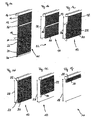
- FIGS. 1a to 1f show an embodiment of a winding device according to the invention in different Maurolllagen, whereby the different coverage conditions are illustrated, which can be realized with the winding device.
- FIGS. 2a to 2f show that too FIGS. 1 equivalent reels of an alternative embodiment of the present invention.
- Fig. 3 shows another alternative embodiment of the present invention.
- FIGS. 4a to 4d show schematic side views of a further alternative embodiment of the winding device according to the invention, which is formed from three joined surface webs.
- FIGS. 1a to 1f illustrate the design and function of a winding device 10 according to the invention.
- the winding device 10 comprises in the illustrated embodiment, a cover 11, which is composed of two differently designed surface webs 12, 22.
- a first surface track 12 is provided with an upper longitudinal side 14 rigidly anchored to a bracket 16.
- a lower longitudinal side 18 of the first surface track 12 is connected to an upper longitudinal side 20 of a second surface track 22, the lower longitudinal side 24 hang down loosely or can be guided laterally by guide elements, not shown here.
- a first winding element 26 Approximately centrally between the upper longitudinal side 14 and the lower longitudinal side 18 of the first surface track 12 there is a first winding element 26, which can provide a rotation for a double-layer winding of the first fabric or surface web 12.
- the second surface web 22 is pulled upwards so that a surface 28 to be covered with the second surface web 22 is variably coverable.
- the first surface web 12 is formed as a loosely woven net grid, while the second surface web 22 is more densely woven or from a closed structure - eg. A film or tarpaulin - may exist.
- a second winding element 30 is arranged, which can provide by an externally applied rotational movement for a single-layer curling of the second surface web 22 from below.
- FIG. 1a The schematic perspective view of Fig. 1a shows the winding device 10 in the fully unrolled state. Both surface webs 12 and 22 are shown unrolled here to their respective full length.
- the cover element 11 can in principle consist of any number of such surface webs, which preferably each have different properties with regard to their permeability to air, light, heat, sound, etc., and thus can be of almost any length.
- the winding device 10 In the completely unrolled form ( Fig. 1a ), the winding device 10 according to the invention is normally not used in practice, since the cover 11 is significantly longer than the surface to be covered 28. By a corresponding winding of the cover 11 on the winding elements 26, 30, the length of the cover 11 to the size of adapted to be covered area 28.
- the area to be covered 28 may, for example, a building opening, a building side wall o. The like. Be. In principle, however, the area 28 to be covered may also be an opening cross-section which is to be opened or closed variably within a building, a hall or another room which can be opened by means of the cover 11 with respect to its permeability to light, air, sound, heat, UV radiation o. The like. Can be variably modified.
- the surface 28 can be variably completely filled with the first surface web 12 (FIG. Fig. 1b ) or completely with the second surface track 22 (FIG. Fig. 1d ) or with the first and the second surface web in any proportions ( Fig. 1c ) or alternatively opened and finally completely uncovered ( FIGS. 1e and 1f ) become.
- Fig. 1b illustrates a first operating position of the winding device 10 according to the invention.
- the second surface web 22 is here almost completely rolled onto the arranged on its lower longitudinal side 24 winding element 30.
- it can also expose a surface 32 which is also to be covered underneath the surface 28 to be covered.
- the first or upper surface to be covered 28 is imposed in the illustrated operating position of the first surface sheet 12, since it is in the fully unrolled state.
- the winding element 26 arranged within the region of the upper surface web 12 is completely free in this position.
- Fig. 1c illustrates a partially rolled up first surface web 12, wherein the first winding element 26 with respect to the representation of the Fig. 1b is rotated, so that the first surface web 12 is partially wound on this and thus shortened.
- the second winding element 30 can be rotated in such a way that the second surface web 22 is partially unrolled. This can happen, for example, by holding the lower winding element 30.
- the lower winding element 30 can also perform an independent rotational movement by its own drive.
- the second surface track 22 is tracked in this way to partially cover the area to be covered 28. In simultaneous or synchronous execution of the two rotational movements in this adjustment, the area to be covered 28 at all times covered with the two surface webs 12, 22, it changes only the ratio in which the two surface webs 12, 22 to cover the surface 28th contribute.
- FIGS. 1e and 1f show how by rotating the second winding element 30, a rolling of the second lower surface web 22 and thus exposing the surface 28 from below takes place.
- Fig. 1f the fully open position of the winding device 10 is reached, in which the surface 28 is largely exposed.
- FIGS. 1b to 1d can also be understood to mean that the second winding element 30 is rotatably fixed in its height in the region at the lower edge of the surface to be covered 28 and not according to the FIGS. 1a, 1e and 1f can be adjusted in height.
- the surface to be covered 28 can not be completely exposed, but only selectively with the first surface 12 (FIG. Fig. 1b ), with the second surface 22 (FIG. Fig. 1d ) or in any division ratio with both surfaces 12, 22 (FIG. Fig. 1c ).
- the second winding element 30 can passively rotate here, since it is mounted laterally. This requires, however, that is provided for a reverse rotation of the second winding element 30, which, for example, by means of a suitable return spring, a suitable other clamping device o. The like. Can be achieved.
- FIGS. 2a to 2f clarify again the corresponding in FIGS. 1a to 1f
- the upper surface web 12 of a plurality of juxtaposed ropes, cords or ribbons which is analogous to the mesh fabric in FIGS. 1a to 1f be rolled onto the corresponding winding element 26 for varying the covering surface.
- FIG. 3 illustrates a further variant in which the second winding element 30 is not arranged on the lower longitudinal side 24 of the second surface web 22, but approximately in the center, so that Also, the second winding element 30 can provide for a two-ply winding the corresponding fabric web 22, as in the first fabric web 12 according to the FIGS. 1a to 1f and 2a to 2f the case is.
- the lower longitudinal side 24 of the second surface 22 can optionally also be fastened to the lower region of the surface 28 to be covered or the opening, for example by a rigid anchoring. In this case, no complete release of the opening is possible, but only an optional or partial covering with the first surface 12 and the second surface 22. Ggf. In this case, the drives (not shown) of the two winding elements 26 and 30 in a predetermined synchronization - either with fixed rotational ratios to each other - are operated to maintain a uniform and tight clothing and to prevent sagging of the cover 11.
- FIGS. 4a to 4d show schematic side views of another alternative embodiment of the winding device 10 according to the invention, the cover 11 is formed of three mutually joined surface webs 12, 22 and 34.
- Fig. 4a illustrates the cover 11 in the fully unrolled state in which the first surface 12 is anchored with its upper longitudinal side 14 rigidly to the bracket 16.
- the lower longitudinal side 18 of the first surface 12 is connected to the upper longitudinal side 20 of the second surface 22, whose lower longitudinal side 24 is in turn connected to an upper longitudinal side 35 of a third surface 34.
- the first winding element 26 is arranged.
- the second winding element 30 is arranged.
- a third winding element 38 is arranged at the lower longitudinal side 36 of the third surface 34.
- FIG. 4b illustrates the covered with the first surface 12 surface 28.
- the second surface 22 and the third surface 34 are in this case on the second winding element 30 (double-layered) or on the third winding element 38 (single-layer) rolled up.
- Second and third winding element 30 and 38 are in this case close to the lower edge of the surface to be covered 28th
- the schematic representation of Fig. 4c illustrates the surface 28 covered with the second surface 22.
- the first surface 12 and the third surface 34 are in this case rolled up on the first winding element 26 (double-layered) or on the third winding element 38 (single-layered).
- the first winding element 26 is located near the upper edge of the surface 28 to be covered.
- the third winding element 38 is located near the lower edge of the surface 28 to be covered.
- the schematic representation of Fig. 4d illustrates the surface 28 covered with the third surface 34.
- the first surface 12 and the second surface 22 are in this case rolled up on the first winding element 26 (double-layered) or on the second winding element 30 (double-layered).
- First and second winding element 26 and 30 are in this case close to the upper edge of the surface to be covered 28.
- the third winding element 38 is in this case close to the lower edge of the surface to be covered 28th
- the first surface 12 may be a UV light impermeable layer that allows welding to be performed in an area of the shop floor without affecting the immediately adjacent areas.
- the second surface 22 may, for example, be a sound-impermeable or noise-insulating layer, which makes it possible to shield adjacent production areas from noisy work.
- the third surface 34 may, for example, be a heat-insulating layer, which may make it possible to carry out loading or production work with the outer doors open in one part of the hall, without exposing adjacent areas to the weather.
Claims (12)
- Dispositif d'enroulement (10), en particulier store à enroulement pour le recouvrement variable de surfaces (28), comprenant au moins deux éléments d'enroulement (26, 30) et au moins un élément de recouvrement (11), le au moins un élément de recouvrement (11) comprenant au moins deux bandes de surface (12, 22, 34) se touchant par leurs arêtes longitudinales, la surface (28) à recouvrir pouvant rester au moins en partie constamment recouverte avec une partie de l'élément de recouvrement (11) en rapport avec l'agencement des au moins deux éléments d'enroulement (26, 30, 38) et les au moins deux bandes de surface (12, 22, 34), pouvant être utilisées pour le recouvrement variable de la surface (28), présentant une conception différente, à chaque fois au moins l'un des éléments d'enroulement (26, 30, 38) rotatifs étant disposé dans la zone d'au moins deux de ces bandes de surface (12, 22, 34), de telle sorte que les bandes de surface (12, 22, 34) respectives peuvent être enroulées à chaque fois de façon variable sur les éléments d'enroulement (26, 30, 38) rotatifs respectifs et que le au moins un élément de recouvrement (11), dans la forme complètement déroulée, est nettement plus long que la surface (28) à recouvrir, caractérisé en ce que la bande de surface (12) disposée tout en haut est ancrée sur une arête supérieure (14) de façon rigide sur un support (16) et en ce que l'élément d'enroulement (26) attribué à la bande de surface (12) supérieure est disposé dans une zone centrale de la bande de surface (12) supérieure, de sorte qu'on a un enroulement à double couche de l'élément de recouvrement (11) autour de l'élément d'enroulement (26) attribué à la bande de surface (12) supérieure.
- Dispositif d'enroulement selon la revendication 1, caractérisé en ce qu'au moins l'une des bandes de surface (12, 22, 34) de conception différente recouvre largement l'ensemble de la surface (28) à recouvrir dans l'état déroulé.
- Dispositif d'enroulement selon la revendication 1, caractérisé en ce que chacune des bandes de surface (12, 22, 34) de conception différente recouvre largement l'ensemble de la surface (28) à recouvrir dans l'état déroulé.
- Dispositif d'enroulement selon l'une quelconque des revendications précédentes, caractérisé en ce que l'un des au moins deux éléments d'enroulement (30 ; 38) est disposé dans la zone d'un bord inférieur de la bande de surface (22 ; 34) disposée tout en bas.
- Dispositif d'enroulement selon la revendication 4, caractérisé en ce qu'une rotation de l'élément d'enroulement (30, 38) disposé tout en bas entraîne un enroulement à une couche de la bande de surface (22, 34) disposée tout en bas.
- Dispositif d'enroulement selon l'une quelconque des revendications précédentes, caractérisé en ce qu'au moins l'une des bandes de surface (12, 22) utilisées est perméable à l'air et/ou à la lumière.
- Dispositif d'enroulement selon la revendication 6, caractérisé en ce que la au moins une bande de surface (12) perméable à l'air et/ou à la lumière est formée à base d'un tissu à mailles fileté et/ou par des câbles disposés verticalement et/ou par des câbles agencés perpendiculairement à la direction d'extension longitudinale des éléments d'enroulement (26, 30, 38).
- Dispositif d'enroulement selon l'une quelconque des revendications 5 à 7, caractérisé en ce que la au moins une bande de surface (22, 34), en particulier imperméable au vent et/ou à la lumière, présente un tissu et/ou une bâche plastique.
- Dispositif d'enroulement selon l'une quelconque des revendications précédentes, caractérisé en ce que la fixation rigide de l'arête supérieure (14) de la bande de surface (12) disposée tout en haut est formée par sa liaison avec une partie de bâtiment fixe.
- Dispositif d'enroulement selon l'une quelconque des revendications précédentes, caractérisé en ce que la fixation rigide de l'arête supérieure (14) de la bande de surface (12) disposée tout en haut s'effectue par sa liaison avec un dispositif de retenue (16) rigide.
- Dispositif d'enroulement selon la revendication 10, caractérisé en ce que le dispositif de retenue (16) rigide pour la fixation de l'arête supérieure (14) de la bande de surface (12) disposée tout en haut peut être réglé de façon variable en hauteur.
- Dispositif d'enroulement selon l'une quelconque des revendications précédentes, caractérisé en ce qu'au moins l'élément d'enroulement (30 ; 38) de la bande de surface (22 ; 34) disposée tout en bas est monté de façon à pouvoir tourner dans une position de hauteur pouvant être prédéfinie.
Priority Applications (1)
| Application Number | Priority Date | Filing Date | Title |
|---|---|---|---|
| PL04024283T PL1522671T3 (pl) | 2003-10-12 | 2004-10-12 | Urządzenie zwijane, zwłaszcza żaluzja zwijana |
Applications Claiming Priority (2)
| Application Number | Priority Date | Filing Date | Title |
|---|---|---|---|
| DE20315853U | 2003-10-12 | ||
| DE20315853U DE20315853U1 (de) | 2003-10-12 | 2003-10-12 | Wickelverfahren für variable Bedeckung von Flächen mit unterschiedlichen Gewebearten |
Publications (4)
| Publication Number | Publication Date |
|---|---|
| EP1522671A2 EP1522671A2 (fr) | 2005-04-13 |
| EP1522671A3 EP1522671A3 (fr) | 2005-11-09 |
| EP1522671B1 true EP1522671B1 (fr) | 2012-02-15 |
| EP1522671B9 EP1522671B9 (fr) | 2012-08-08 |
Family
ID=31984636
Family Applications (1)
| Application Number | Title | Priority Date | Filing Date |
|---|---|---|---|
| EP04024283A Active EP1522671B9 (fr) | 2003-10-12 | 2004-10-12 | Store à rouleau |
Country Status (4)
| Country | Link |
|---|---|
| EP (1) | EP1522671B9 (fr) |
| AT (1) | ATE545759T1 (fr) |
| DE (1) | DE20315853U1 (fr) |
| PL (1) | PL1522671T3 (fr) |
Cited By (1)
| Publication number | Priority date | Publication date | Assignee | Title |
|---|---|---|---|---|
| US20160130873A1 (en) * | 2014-11-10 | 2016-05-12 | Lock Antriebstechnik Gmbh | Winding device for covering of building openings |
Families Citing this family (2)
| Publication number | Priority date | Publication date | Assignee | Title |
|---|---|---|---|---|
| DE20315853U1 (de) * | 2003-10-12 | 2004-03-04 | Zettl, Markus | Wickelverfahren für variable Bedeckung von Flächen mit unterschiedlichen Gewebearten |
| GB2431190B (en) * | 2005-10-13 | 2010-02-24 | John Benjamin Slater | Adjustable screen |
Citations (1)
| Publication number | Priority date | Publication date | Assignee | Title |
|---|---|---|---|---|
| EP1522671A2 (fr) * | 2003-10-12 | 2005-04-13 | Markus Zettl | Store à rouleau |
Family Cites Families (9)
| Publication number | Priority date | Publication date | Assignee | Title |
|---|---|---|---|---|
| US3306344A (en) * | 1965-10-11 | 1967-02-28 | R L Kuss And Company Inc | Flexible closure |
| FR2211585B1 (fr) * | 1972-12-21 | 1976-08-27 | Nijmegen Metaal Nv | |
| US4809760A (en) * | 1979-03-14 | 1989-03-07 | Lew Hyok S | Self-coiling partition |
| DE4213108C2 (de) | 1992-04-21 | 1995-10-26 | Hueppe Form Sonnenschutz | Abdeckung mit mehreren parallelen Rollos |
| DE9210938U1 (fr) | 1992-08-15 | 1992-12-17 | Remis Gesellschaft Fuer Entwicklung Und Vertrieb Von Technischen Elementen Mbh Koeln, 5000 Koeln, De | |
| SE524182C2 (sv) * | 2002-03-13 | 2004-07-06 | Ronny Kogsta | Rullgardinssystem, förfarande för montering av rullgardin samt monteringsfärdig rullgardinssats |
| DE20212193U1 (de) | 2002-08-07 | 2002-12-12 | Lock Antriebstechnik Gmbh | Wickeljalousie |
| DE20214076U1 (de) | 2002-09-10 | 2003-05-08 | Bvba Vervaeke Ruiselede | Vorrichtung zum Abschirmen eines Raumes |
| DE20320335U1 (de) | 2003-08-07 | 2004-06-17 | Lock Antriebstechnik Gmbh | Wickeljalousie |
-
2003
- 2003-10-12 DE DE20315853U patent/DE20315853U1/de not_active Expired - Lifetime
-
2004
- 2004-10-12 PL PL04024283T patent/PL1522671T3/pl unknown
- 2004-10-12 EP EP04024283A patent/EP1522671B9/fr active Active
- 2004-10-12 AT AT04024283T patent/ATE545759T1/de active
Patent Citations (1)
| Publication number | Priority date | Publication date | Assignee | Title |
|---|---|---|---|---|
| EP1522671A2 (fr) * | 2003-10-12 | 2005-04-13 | Markus Zettl | Store à rouleau |
Cited By (1)
| Publication number | Priority date | Publication date | Assignee | Title |
|---|---|---|---|---|
| US20160130873A1 (en) * | 2014-11-10 | 2016-05-12 | Lock Antriebstechnik Gmbh | Winding device for covering of building openings |
Also Published As
| Publication number | Publication date |
|---|---|
| PL1522671T3 (pl) | 2012-07-31 |
| ATE545759T1 (de) | 2012-03-15 |
| DE20315853U1 (de) | 2004-03-04 |
| EP1522671B9 (fr) | 2012-08-08 |
| EP1522671A2 (fr) | 2005-04-13 |
| EP1522671A3 (fr) | 2005-11-09 |
Similar Documents
| Publication | Publication Date | Title |
|---|---|---|
| DE69637425T2 (de) | Abdichtbare Abdeckung | |
| DE3521084C2 (fr) | ||
| EP0089657B1 (fr) | Store isolant | |
| DE3643233A1 (de) | Vorgefertigte fenster- und rolladenvorrichtung fuer haeuser u.dgl. | |
| DE102015117548B4 (de) | Verschlussvorrichtung und Verfahren zur Montage einer Verschlussvorrichtung für eine Bauwerksöffnung | |
| EP1522671B9 (fr) | Store à rouleau | |
| DE60031591T2 (de) | In zwei Teile geteilter Rolladen mit variablem Fenster | |
| DE2744451A1 (de) | Verschlusseinrichtung fuer fenster, tueren o.dgl. oeffnungen | |
| DE202004020298U1 (de) | Wickelvorrichtung, insbesondere Wickeljalousie | |
| DE102007003233A1 (de) | Vorrichtung zur Beeinflussung der Durchlässigkeit von Hüllkonstruktionen | |
| DE19960032A1 (de) | Auf- und abwickelbares Rollo | |
| EP1300541A2 (fr) | Caisson de volet roulant | |
| EP0693614A1 (fr) | Dispositif d'ombrage | |
| DE19830195B4 (de) | Verschlusseinrichtung für Einfahröffnungen, insbesondere von Garagen | |
| DE19833031C1 (de) | Rollo | |
| DE19805272A1 (de) | Einrichtung zum Schützen, Abdecken, Verschließen, Abtrennen o. dgl. Abgrenzen von Bereichen | |
| DE4220434A1 (de) | Schallschutzvorrichtung für Gebäude | |
| DE19808624C1 (de) | Fassadenrollo | |
| DE2639275A1 (de) | Rollo fuer fenster, tueren oder dergleichen | |
| DE3227721A1 (de) | Rolladen fuer fenster und tueren an gebaeuden | |
| DE19515426A1 (de) | Abdeckungsvorrichtung | |
| DE102020105229A1 (de) | Vorrichtung zum Abschatten eines Raums und Verfahren zur Steuerung der Vorrichtung | |
| DE102007002075B4 (de) | Rollladenkasten mit einer Walze und einem darauf gewickelten Rollladen | |
| WO2023061917A1 (fr) | Dispositif d'aménagement de façade à fixer dans la zone d'une ouverture extérieure d'un bâtiment | |
| DE3000112A1 (de) | Einrichtung zur innenausstattung |
Legal Events
| Date | Code | Title | Description |
|---|---|---|---|
| PUAI | Public reference made under article 153(3) epc to a published international application that has entered the european phase |
Free format text: ORIGINAL CODE: 0009012 |
|
| AK | Designated contracting states |
Kind code of ref document: A2 Designated state(s): AT BE BG CH CY CZ DE DK EE ES FI FR GB GR HU IE IT LI LU MC NL PL PT RO SE SI SK TR |
|
| AX | Request for extension of the european patent |
Extension state: AL HR LT LV MK |
|
| PUAL | Search report despatched |
Free format text: ORIGINAL CODE: 0009013 |
|
| AK | Designated contracting states |
Kind code of ref document: A3 Designated state(s): AT BE BG CH CY CZ DE DK EE ES FI FR GB GR HU IE IT LI LU MC NL PL PT RO SE SI SK TR |
|
| AX | Request for extension of the european patent |
Extension state: AL HR LT LV MK |
|
| 17P | Request for examination filed |
Effective date: 20060221 |
|
| RAP1 | Party data changed (applicant data changed or rights of an application transferred) |
Owner name: ZETTL, MARKUS |
|
| RIN1 | Information on inventor provided before grant (corrected) |
Inventor name: ZETTL, MARKUS |
|
| AKX | Designation fees paid |
Designated state(s): AT BE BG CH CY CZ DE DK EE ES FI FR GB GR HU IE IT LI LU MC NL PL PT RO SE SI SK TR |
|
| 17Q | First examination report despatched |
Effective date: 20060904 |
|
| GRAP | Despatch of communication of intention to grant a patent |
Free format text: ORIGINAL CODE: EPIDOSNIGR1 |
|
| GRAS | Grant fee paid |
Free format text: ORIGINAL CODE: EPIDOSNIGR3 |
|
| GRAA | (expected) grant |
Free format text: ORIGINAL CODE: 0009210 |
|
| AK | Designated contracting states |
Kind code of ref document: B1 Designated state(s): AT BE BG CH CY CZ DE DK EE ES FI FR GB GR HU IE IT LI LU MC NL PL PT RO SE SI SK TR |
|
| REG | Reference to a national code |
Ref country code: GB Ref legal event code: FG4D Free format text: NOT ENGLISH Ref country code: CH Ref legal event code: EP |
|
| REG | Reference to a national code |
Ref country code: IE Ref legal event code: FG4D Free format text: LANGUAGE OF EP DOCUMENT: GERMAN |
|
| REG | Reference to a national code |
Ref country code: AT Ref legal event code: REF Ref document number: 545759 Country of ref document: AT Kind code of ref document: T Effective date: 20120315 |
|
| REG | Reference to a national code |
Ref country code: DE Ref legal event code: R096 Ref document number: 502004013293 Country of ref document: DE Effective date: 20120412 |
|
| REG | Reference to a national code |
Ref country code: RO Ref legal event code: EPE |
|
| REG | Reference to a national code |
Ref country code: NL Ref legal event code: T3 |
|
| REG | Reference to a national code |
Ref country code: PL Ref legal event code: T3 |
|
| PG25 | Lapsed in a contracting state [announced via postgrant information from national office to epo] |
Ref country code: FI Free format text: LAPSE BECAUSE OF FAILURE TO SUBMIT A TRANSLATION OF THE DESCRIPTION OR TO PAY THE FEE WITHIN THE PRESCRIBED TIME-LIMIT Effective date: 20120215 Ref country code: PT Free format text: LAPSE BECAUSE OF FAILURE TO SUBMIT A TRANSLATION OF THE DESCRIPTION OR TO PAY THE FEE WITHIN THE PRESCRIBED TIME-LIMIT Effective date: 20120615 Ref country code: GR Free format text: LAPSE BECAUSE OF FAILURE TO SUBMIT A TRANSLATION OF THE DESCRIPTION OR TO PAY THE FEE WITHIN THE PRESCRIBED TIME-LIMIT Effective date: 20120516 |
|
| REG | Reference to a national code |
Ref country code: IE Ref legal event code: FD4D |
|
| PG25 | Lapsed in a contracting state [announced via postgrant information from national office to epo] |
Ref country code: CY Free format text: LAPSE BECAUSE OF FAILURE TO SUBMIT A TRANSLATION OF THE DESCRIPTION OR TO PAY THE FEE WITHIN THE PRESCRIBED TIME-LIMIT Effective date: 20120215 |
|
| PG25 | Lapsed in a contracting state [announced via postgrant information from national office to epo] |
Ref country code: EE Free format text: LAPSE BECAUSE OF FAILURE TO SUBMIT A TRANSLATION OF THE DESCRIPTION OR TO PAY THE FEE WITHIN THE PRESCRIBED TIME-LIMIT Effective date: 20120215 Ref country code: IE Free format text: LAPSE BECAUSE OF FAILURE TO SUBMIT A TRANSLATION OF THE DESCRIPTION OR TO PAY THE FEE WITHIN THE PRESCRIBED TIME-LIMIT Effective date: 20120215 Ref country code: SI Free format text: LAPSE BECAUSE OF FAILURE TO SUBMIT A TRANSLATION OF THE DESCRIPTION OR TO PAY THE FEE WITHIN THE PRESCRIBED TIME-LIMIT Effective date: 20120215 Ref country code: SE Free format text: LAPSE BECAUSE OF FAILURE TO SUBMIT A TRANSLATION OF THE DESCRIPTION OR TO PAY THE FEE WITHIN THE PRESCRIBED TIME-LIMIT Effective date: 20120215 Ref country code: DK Free format text: LAPSE BECAUSE OF FAILURE TO SUBMIT A TRANSLATION OF THE DESCRIPTION OR TO PAY THE FEE WITHIN THE PRESCRIBED TIME-LIMIT Effective date: 20120215 |
|
| REG | Reference to a national code |
Ref country code: HU Ref legal event code: AG4A Ref document number: E014500 Country of ref document: HU |
|
| PG25 | Lapsed in a contracting state [announced via postgrant information from national office to epo] |
Ref country code: SK Free format text: LAPSE BECAUSE OF FAILURE TO SUBMIT A TRANSLATION OF THE DESCRIPTION OR TO PAY THE FEE WITHIN THE PRESCRIBED TIME-LIMIT Effective date: 20120215 Ref country code: IT Free format text: LAPSE BECAUSE OF FAILURE TO SUBMIT A TRANSLATION OF THE DESCRIPTION OR TO PAY THE FEE WITHIN THE PRESCRIBED TIME-LIMIT Effective date: 20120215 |
|
| PLBE | No opposition filed within time limit |
Free format text: ORIGINAL CODE: 0009261 |
|
| STAA | Information on the status of an ep patent application or granted ep patent |
Free format text: STATUS: NO OPPOSITION FILED WITHIN TIME LIMIT |
|
| 26N | No opposition filed |
Effective date: 20121116 |
|
| REG | Reference to a national code |
Ref country code: DE Ref legal event code: R097 Ref document number: 502004013293 Country of ref document: DE Effective date: 20121116 |
|
| PG25 | Lapsed in a contracting state [announced via postgrant information from national office to epo] |
Ref country code: ES Free format text: LAPSE BECAUSE OF FAILURE TO SUBMIT A TRANSLATION OF THE DESCRIPTION OR TO PAY THE FEE WITHIN THE PRESCRIBED TIME-LIMIT Effective date: 20120526 |
|
| PG25 | Lapsed in a contracting state [announced via postgrant information from national office to epo] |
Ref country code: MC Free format text: LAPSE BECAUSE OF NON-PAYMENT OF DUE FEES Effective date: 20121031 |
|
| PG25 | Lapsed in a contracting state [announced via postgrant information from national office to epo] |
Ref country code: BG Free format text: LAPSE BECAUSE OF FAILURE TO SUBMIT A TRANSLATION OF THE DESCRIPTION OR TO PAY THE FEE WITHIN THE PRESCRIBED TIME-LIMIT Effective date: 20120515 |
|
| PG25 | Lapsed in a contracting state [announced via postgrant information from national office to epo] |
Ref country code: LU Free format text: LAPSE BECAUSE OF NON-PAYMENT OF DUE FEES Effective date: 20121012 |
|
| REG | Reference to a national code |
Ref country code: FR Ref legal event code: PLFP Year of fee payment: 12 |
|
| REG | Reference to a national code |
Ref country code: FR Ref legal event code: PLFP Year of fee payment: 13 |
|
| PGFP | Annual fee paid to national office [announced via postgrant information from national office to epo] |
Ref country code: RO Payment date: 20160927 Year of fee payment: 13 |
|
| PGFP | Annual fee paid to national office [announced via postgrant information from national office to epo] |
Ref country code: TR Payment date: 20160927 Year of fee payment: 13 |
|
| PGFP | Annual fee paid to national office [announced via postgrant information from national office to epo] |
Ref country code: HU Payment date: 20161019 Year of fee payment: 13 Ref country code: CZ Payment date: 20161011 Year of fee payment: 13 |
|
| REG | Reference to a national code |
Ref country code: FR Ref legal event code: PLFP Year of fee payment: 14 |
|
| PG25 | Lapsed in a contracting state [announced via postgrant information from national office to epo] |
Ref country code: CZ Free format text: LAPSE BECAUSE OF NON-PAYMENT OF DUE FEES Effective date: 20171012 |
|
| PG25 | Lapsed in a contracting state [announced via postgrant information from national office to epo] |
Ref country code: RO Free format text: LAPSE BECAUSE OF NON-PAYMENT OF DUE FEES Effective date: 20171012 Ref country code: HU Free format text: LAPSE BECAUSE OF NON-PAYMENT OF DUE FEES Effective date: 20171013 |
|
| REG | Reference to a national code |
Ref country code: FR Ref legal event code: PLFP Year of fee payment: 15 |
|
| PGFP | Annual fee paid to national office [announced via postgrant information from national office to epo] |
Ref country code: NL Payment date: 20201028 Year of fee payment: 17 |
|
| PGFP | Annual fee paid to national office [announced via postgrant information from national office to epo] |
Ref country code: FR Payment date: 20201021 Year of fee payment: 17 |
|
| PGFP | Annual fee paid to national office [announced via postgrant information from national office to epo] |
Ref country code: GB Payment date: 20211022 Year of fee payment: 18 |
|
| PGFP | Annual fee paid to national office [announced via postgrant information from national office to epo] |
Ref country code: BE Payment date: 20211020 Year of fee payment: 18 |
|
| PGFP | Annual fee paid to national office [announced via postgrant information from national office to epo] |
Ref country code: PL Payment date: 20211011 Year of fee payment: 18 |
|
| REG | Reference to a national code |
Ref country code: NL Ref legal event code: MM Effective date: 20211101 |
|
| PG25 | Lapsed in a contracting state [announced via postgrant information from national office to epo] |
Ref country code: TR Free format text: LAPSE BECAUSE OF NON-PAYMENT OF DUE FEES Effective date: 20171012 |
|
| PG25 | Lapsed in a contracting state [announced via postgrant information from national office to epo] |
Ref country code: NL Free format text: LAPSE BECAUSE OF NON-PAYMENT OF DUE FEES Effective date: 20211101 |
|
| PG25 | Lapsed in a contracting state [announced via postgrant information from national office to epo] |
Ref country code: FR Free format text: LAPSE BECAUSE OF NON-PAYMENT OF DUE FEES Effective date: 20211031 |
|
| REG | Reference to a national code |
Ref country code: BE Ref legal event code: MM Effective date: 20221031 |
|
| GBPC | Gb: european patent ceased through non-payment of renewal fee |
Effective date: 20221012 |
|
| PG25 | Lapsed in a contracting state [announced via postgrant information from national office to epo] |
Ref country code: BE Free format text: LAPSE BECAUSE OF NON-PAYMENT OF DUE FEES Effective date: 20221031 |
|
| PG25 | Lapsed in a contracting state [announced via postgrant information from national office to epo] |
Ref country code: GB Free format text: LAPSE BECAUSE OF NON-PAYMENT OF DUE FEES Effective date: 20221012 |
|
| PG25 | Lapsed in a contracting state [announced via postgrant information from national office to epo] |
Ref country code: PL Free format text: LAPSE BECAUSE OF NON-PAYMENT OF DUE FEES Effective date: 20221012 |
|
| PGFP | Annual fee paid to national office [announced via postgrant information from national office to epo] |
Ref country code: DE Payment date: 20231020 Year of fee payment: 20 Ref country code: CH Payment date: 20231102 Year of fee payment: 20 Ref country code: AT Payment date: 20231020 Year of fee payment: 20 |