EP1521663B1 - Procede et dispositif pour rectifier un cylindre rotatif a l'aide d'un support de lunette fixe elastique - Google Patents
Procede et dispositif pour rectifier un cylindre rotatif a l'aide d'un support de lunette fixe elastique Download PDFInfo
- Publication number
- EP1521663B1 EP1521663B1 EP03763887A EP03763887A EP1521663B1 EP 1521663 B1 EP1521663 B1 EP 1521663B1 EP 03763887 A EP03763887 A EP 03763887A EP 03763887 A EP03763887 A EP 03763887A EP 1521663 B1 EP1521663 B1 EP 1521663B1
- Authority
- EP
- European Patent Office
- Prior art keywords
- roller
- grinding
- padding body
- contact
- grinding wheel
- Prior art date
- Legal status (The legal status is an assumption and is not a legal conclusion. Google has not performed a legal analysis and makes no representation as to the accuracy of the status listed.)
- Expired - Lifetime
Links
- 238000000034 method Methods 0.000 title claims description 53
- 239000000314 lubricant Substances 0.000 claims description 21
- 239000007788 liquid Substances 0.000 claims description 8
- 238000001816 cooling Methods 0.000 claims description 5
- 230000001050 lubricating effect Effects 0.000 claims description 5
- 230000002093 peripheral effect Effects 0.000 claims description 5
- 230000006978 adaptation Effects 0.000 claims description 2
- 230000008878 coupling Effects 0.000 claims description 2
- 238000010168 coupling process Methods 0.000 claims description 2
- 238000005859 coupling reaction Methods 0.000 claims description 2
- 238000006073 displacement reaction Methods 0.000 claims description 2
- 239000000839 emulsion Substances 0.000 claims description 2
- 239000003921 oil Substances 0.000 claims description 2
- 239000013013 elastic material Substances 0.000 claims 2
- 239000007787 solid Substances 0.000 claims 2
- 230000003213 activating effect Effects 0.000 claims 1
- 239000005068 cooling lubricant Substances 0.000 claims 1
- 238000013016 damping Methods 0.000 abstract description 13
- 230000001172 regenerating effect Effects 0.000 abstract description 6
- 239000011343 solid material Substances 0.000 abstract description 3
- 230000008569 process Effects 0.000 description 16
- 239000002826 coolant Substances 0.000 description 7
- 241000951498 Brachypteraciidae Species 0.000 description 3
- 229910000831 Steel Inorganic materials 0.000 description 3
- 230000000694 effects Effects 0.000 description 3
- 230000002706 hydrostatic effect Effects 0.000 description 3
- 239000002184 metal Substances 0.000 description 3
- 239000010959 steel Substances 0.000 description 3
- 238000005299 abrasion Methods 0.000 description 2
- 239000000919 ceramic Substances 0.000 description 2
- 230000008859 change Effects 0.000 description 2
- 229910052593 corundum Inorganic materials 0.000 description 2
- 239000010431 corundum Substances 0.000 description 2
- 238000003754 machining Methods 0.000 description 2
- 238000004519 manufacturing process Methods 0.000 description 2
- 239000000463 material Substances 0.000 description 2
- 230000010355 oscillation Effects 0.000 description 2
- 239000004033 plastic Substances 0.000 description 2
- 238000012545 processing Methods 0.000 description 2
- 230000009471 action Effects 0.000 description 1
- 230000004323 axial length Effects 0.000 description 1
- 210000001217 buttock Anatomy 0.000 description 1
- 238000010276 construction Methods 0.000 description 1
- 238000013461 design Methods 0.000 description 1
- 238000011161 development Methods 0.000 description 1
- 230000018109 developmental process Effects 0.000 description 1
- 238000010586 diagram Methods 0.000 description 1
- 238000005516 engineering process Methods 0.000 description 1
- 230000005284 excitation Effects 0.000 description 1
- 238000002474 experimental method Methods 0.000 description 1
- 239000006260 foam Substances 0.000 description 1
- 239000010687 lubricating oil Substances 0.000 description 1
- 238000005461 lubrication Methods 0.000 description 1
- 238000010327 methods by industry Methods 0.000 description 1
- 230000000284 resting effect Effects 0.000 description 1
- 238000004904 shortening Methods 0.000 description 1
- 238000003860 storage Methods 0.000 description 1
- 238000012549 training Methods 0.000 description 1
- XLYOFNOQVPJJNP-UHFFFAOYSA-N water Substances O XLYOFNOQVPJJNP-UHFFFAOYSA-N 0.000 description 1
Images


Classifications
-
- B—PERFORMING OPERATIONS; TRANSPORTING
- B24—GRINDING; POLISHING
- B24B—MACHINES, DEVICES, OR PROCESSES FOR GRINDING OR POLISHING; DRESSING OR CONDITIONING OF ABRADING SURFACES; FEEDING OF GRINDING, POLISHING, OR LAPPING AGENTS
- B24B5/00—Machines or devices designed for grinding surfaces of revolution on work, including those which also grind adjacent plane surfaces; Accessories therefor
- B24B5/02—Machines or devices designed for grinding surfaces of revolution on work, including those which also grind adjacent plane surfaces; Accessories therefor involving centres or chucks for holding work
- B24B5/04—Machines or devices designed for grinding surfaces of revolution on work, including those which also grind adjacent plane surfaces; Accessories therefor involving centres or chucks for holding work for grinding cylindrical surfaces externally
-
- B—PERFORMING OPERATIONS; TRANSPORTING
- B24—GRINDING; POLISHING
- B24B—MACHINES, DEVICES, OR PROCESSES FOR GRINDING OR POLISHING; DRESSING OR CONDITIONING OF ABRADING SURFACES; FEEDING OF GRINDING, POLISHING, OR LAPPING AGENTS
- B24B41/00—Component parts such as frames, beds, carriages, headstocks
- B24B41/007—Weight compensation; Temperature compensation; Vibration damping
-
- B—PERFORMING OPERATIONS; TRANSPORTING
- B24—GRINDING; POLISHING
- B24B—MACHINES, DEVICES, OR PROCESSES FOR GRINDING OR POLISHING; DRESSING OR CONDITIONING OF ABRADING SURFACES; FEEDING OF GRINDING, POLISHING, OR LAPPING AGENTS
- B24B41/00—Component parts such as frames, beds, carriages, headstocks
- B24B41/06—Work supports, e.g. adjustable steadies
- B24B41/065—Steady rests
Definitions
- the invention relates to a method and a device according to the preamble of claim 1 or 17.
- a method and such a device is known from DE 16 27 998 A.
- slender, elongate rolls are required which rotate during operation, are partly driven and often have to be heated or cooled from the inside.
- Such rolls may for example have a length of about 1000 mm and a diameter of 85 mm.
- the rollers are also often tubular with a small wall thickness down to 1 mm. High demands are placed on the surface quality of these rolls and on their dimensional accuracy. The grinding of such rolls to the finished size and the required surface finish therefore places high demands on the expert's skill.
- a known disadvantageous aspect of external grinding of rollers is that they deflect laterally when the grinding wheel acts on its peripheral surface. This can lead to the finished roll deviating from the cylindrical shape.
- the roller gets into self-excited transverse vibrations, the so-called regenerative rattling.
- the result of this regenerative rattling are chatter marks on the peripheral surface of the roll, which mean a reduced surface quality and render the resulting roll useless for many applications.
- a well-known from practice in the method of the type mentioned is that the roller is first pre-ground in Einstech psychologist with an existing corundum grinding wheel. For this purpose, the roller is processed to a roughing in the way that the grinding wheel is pierced several times side by side until the whole length of the roller is pre-ground to this degree. Subsequently, the same grinding wheel is dressed and then fine or finish ground.
- the finish grinding is carried out by longitudinal grinding, wherein the rotating grinding wheel and the rotating roller are moved in the longitudinal direction of the roller at its outer periphery relative to each other.
- With a length of the roller of, for example, 1000 mm grinding wheels with a width of, for example, 100 mm are used for this purpose.
- the disadvantage of the known method is that the grinding wheels consisting of corundum often have to be dressed. This may also be required during a single finish grinding operation. Overall, the known grinding process is very tedious.
- a follower buttstock for supporting cylindrical workpieces in a grinding machine which forms a hydrostatic half bearing.
- the rotating workpiece to be ground thus rests on a liquid film, which must be constantly renewed.
- a liquid flow is continuously fed to the hydrostatic half bearing.
- the liquid can be a coolant that is required anyway during grinding.
- the invention is therefore an object of the invention to provide a method of the type mentioned, which allows the use of CBN grinding wheels and significantly reduced processing times, while still leading to rollers of high dimensional accuracy and surface quality.
- the pad body is made in the circumferential area opposite the grinding wheel to the roller to be ground, the transverse vibrations of the roller as well as resulting from the grinding wheel vibrations are successfully damped. The regenerative rattle does not occur, and thus the dreaded chatter marks are no longer recorded.
- the upholstery body does not lead to any running marks which mean reduced surface quality and can be recognized immediately by the person skilled in the art.
- the requirement of the circumference area opposite the grinding wheel means that the cushion body, for instance, is to be mounted radially opposite the grinding wheel on the opposite side of the roller.
- the inventive method as longitudinal grinding, wherein the rotating grinding wheel 13 and the rotating roller 6 are moved in the longitudinal direction of the roller 6 at the outer periphery relative to each other.
- the roller which is mounted in tips and driven by this or by a driver for rotation, are passed on a grinding table on the rotating grinding wheel.
- the continuous longitudinal grinding better corresponds to an automated procedure than the piercing grinding required in paragraphs; moreover, there is no problem of the grinding marks at the crossing points.
- a particularly advantageous embodiment of the method according to the invention is therefore that the roller 6 in one single clamping successively with one ceramic bonded CBN grinding wheel 12, 13 is pre-ground and finished and the employment of the cushion body 6 at least during regrinding.
- the following advantageous embodiments of the method according to the invention relate to how the cushion body - hereinafter collectively referred to as a "resilient pad" - hired to the roller and optionally moved towards her.
- the pad 15 is employed elastically yielding to the roller 6.
- this can be done by a linear guide with a positioning spring whose tension is adjustable.
- the employment by a pressure medium, but also an electronically controlled employment by electric motors is conceivable.
- the contact force with which the resilient pad 15 is made to the roller 6, is adjustable and can also be zero before the start of the grinding process.
- the employment of the at least one resilient pad is because the roller bends under the influence of the machining forces of the grinding wheel in the direction of the pad.
- a control of the adjusting force which can be controlled particularly well from a technical point of view, results from a pneumatic adjustment of the yielding cushion 15 to the roller 6.
- the simplest method of the invention according to another embodiment is carried out in that the employment of the at least one resilient pad during grinding takes place at a constant point in the longitudinal extent of the roller. For example, if the roller is mounted between tips and the grinding wheel is guided past the outer circumference of the roller in the longitudinal direction, it is preferable to arrange the resilient pad substantially in the axial center of the roller, because there the strongest transverse vibrations occur.
- the resilient pad 15, 23, 26, 34 adapts to the cylindrical contour when it is being set against the roller 6 to be ground.
- the adaptation can be carried out particularly advantageously in that a pressure medium, in particular a gas, acts on a flexible outer skin of the pad 23, 26, 34 resting against the roller to be ground 6 from the inside. In this way, the pad is inflated like a balloon that adapts softly to an obstacle.
- the contact point of the resilient pad 23, 26, 34 is supplied to the roller 6, a liquid or gaseous lubricant.
- the associated method can be particularly easily designed in such a way that the lubricant is formed by the pressure medium of the pad 34 and the contact point is supplied through outlet openings 35, which are in the roller 6 facing outer skin of the pad 34.
- a certain longitudinal contour of the roller during grinding can be achieved by setting the compliant cushion across the roller so that the roller deflects during the grinding process and by grinding in the final state a longitudinal contour of the roller with a slight concave or convex curvature comes.
- the roller here assumes a desired deflection during grinding, without transverse vibrations occurring. If the compliant pad has a certain distance from its outer periphery when the roller is at rest, the roller will deflect under the influence of the wheel until it touches the pad. But also the setting of a bias voltage is possible, in which case the roller is bulged in the direction of the grinding wheel. With proper control of the corresponding grinding processes arise rollers with an axial longitudinal contour, which runs in the desired manner concave or convex.
- the resulting transverse vibrations also change, depending on in which axial region of the roll the grinding wheel is currently located. Therefore, it is advantageous for fine tuning of the grinding process when the contact force of the at least one resilient pad is changed during the grinding process and / or is set to different values for a plurality of pads 39, 40, 41.
- the change in the contact force is carried out in accordance with the respective axial region of the roller, in which the grinding wheel and / or the pad just act on the roller. The required values can be quickly determined by calculations or practical experiments.
- the invention also relates to a device for external grinding of rollers, in particular for carrying out the method according to the invention according to the above-cited claims.
- a device for external grinding of rollers in particular for carrying out the method according to the invention according to the above-cited claims.
- the invention provided according to claim 17 is thus an apparatus for grinding outer rollers 6, in particular for carrying out the method according to claims 1 to 16, with clamping and Antriebsgliedem for clamping the roller 6 at its front ends and for the rotary drive of the roller 6, with at least a grinding wheel 13 driving grinding spindle 11 which is movable in a direction transverse to the longitudinal axis of the roller 6, whereby the grinding wheel 13 against the roller 6 can be adjusted, with drives for mutual longitudinal displacement of roller 6 and grinding wheel 13 and at least one in the periphery of the roller 6 located opposite the grinding wheel 13 device 14 through which a cushion body 15, 23, 26, 34, 39, 40, 41 of a resilient solid material or an elastic, filled with an elastic pressure medium outer skin also transverse to the longitudinal direction of the
- the means for adjusting the cushion body may for example be provided on the machine bed or on a grinding table which also carries the roll to be ground.
- the hiring can be done mechanically, electrically or by a pressure medium.
- the following embodiments relate to how the contact force can be constructively advantageous and selectively applied in height.
- a control arrangement for adjusting the adjusting force is provided, with which the resilient pad 15 is employed against the circumference of the roller 6 to be ground.
- each pad 39, 40, 41 can be adjusted individually and independently of the other pads.
- the device for adjusting the resilient pad 15 comprises a double-acting pneumatic push cylinder 17, on the piston rod 19, the pad 15 is attached. If a plurality of flexible pads 39, 40, 41 arranged along the roller 6 to be ground are present, then each pneumatic push cylinder is assigned its own pressure control valve 44, 45, 46. In this way, a perfect pneumatic control is ensured, with which the vibrations are successfully damped at several points of the axial extent of the roller.
- the resilient pad 15 is formed by a body of a resilient solid material.
- a high-quality, with closed cells trained foam plastic which has an abrasion-resistant surface or is provided with it, can already fulfill this task well. It will already adapt to a certain extent to the outer contour of the roller and thus successfully dampen the vibrations.
- the resilient pad 23 is formed by a hollow body of an elastic outer skin in which a pressure medium is located.
- This pressure medium may be a gas, preferably compressed air.
- a pressurized hollow body is adapted to the outer contour of the roller particularly well suited, the effect can still be controlled by the fact that the internal pressure is optimally adjusted depending on the grinding process to be performed.
- lubrication and cooling agent is supplied to the contact point.
- supply lines are provided according to an advantageous embodiment, which open in the region of the contact point of the resilient pad on the roller and through which the contact point, a lubricant is supplied.
- Suitable lubricants are the grinding emulsions, synthetic coolants and grinding oils customary in grinding technology. But also compressed air can be considered. If the supply lines leading the lubricant are guided through the resilient pad directly to the contact point of the pad on the roller, then the lubricant is located directly where it can act most strongly.
- a film forms between the roller and the compliant pad, which corresponds to the hydroplaning of the automobile tire and is particularly effective. If lubricated with compressed air, so an air cushion can be formed, as it is known from hovercraft. It must be emphasized that the lubricant film or air cushion effectively reduces the friction losses during grinding without thereby reducing the effect of vibration damping.
- a structurally particularly effective solution consists in that the supply lines leading through the flexible cushion 26 are designed as hoses 30 which are made in one piece with the elastic outer skin of the pad 26, the lubricant and the pressure medium being separated from one another.
- the pressure medium of the pad itself as a coolant in question it is structurally particularly simple that the elastic outer skin of the resilient pad 34 at its facing the roller to be grounded 6 contact surface with a variety is provided by outlet openings through which passes the pressure medium to form the cooling and lubricating film to the contact point.
- this training must thus constantly pressure medium from the resilient pad to the contact point to pass outwards. It is a constant supply of the pressure medium required, which, however, is easy to control by pressure control valves.
- the solution can be perfected even further by the fact that the pneumatic control of the push cylinder, on whose piston rod the yielding cushion is located, is also included in the process.
- a wheel spindle 8 with two grinding spindles 10, 11 is provided, which can be brought selectively into operative position and of which the first 10 carries a ceramically bonded CBN grinding wheel 12 for rough grinding and the second a ceramically bonded CBN grinding wheel 13 for finish grinding, wherein an automatic coupling is provided by which the at least one means for adjusting the resilient pad 15 to the To be ground roller 6 is activated when the second grinding spindle 11 is brought into operative position.
- the device according to the invention is prepared in this way for automation, which is often desired in modern mass production on production lines.
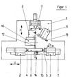
- FIG. 1 is a schematic representation of a conventional cylindrical grinding machine for external grinding of cylindrical parts.
- a machine bed 1 can be seen, on which a workpiece headstock 2 and a tailstock 3 are located.
- Workpiece headstock 2 and tailstock 3 are mutually adjustable in the axial direction, so that by means of the tips 4 and 5 located on them, the roller 6 to be ground can be clamped and driven for rotation.
- the roller can also be driven by drivers, which are customary and therefore not shown separately here.
- the workpiece headstock 2 and the tailstock 3 are located on a grinding table 7, which can be moved as a whole in the Z direction.
- the grinding headstock carries a first grinding spindle 10 and a second grinding spindle 11.
- the first grinding spindle 10 carries a first grinding wheel 12, which serves for roughing or roughing
- the second grinding spindle 11 carries a second grinding wheel 13 intended for finish grinding or finishing.
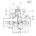
- the wheelhead 8 By pivoting about the vertical pivot axis 9, the wheelhead 8 moves in the direction of arrow B, so that either the grinding wheel 12 ( Figure 1) or the second grinding wheel 13 ( Figure 2) can be brought into operative position.
- the entire wheelhead 8 can be moved numerically controlled in the X direction, whereby the grinding wheel, which is in the active position in each case, comes into contact with the roller 6 to be grounded in a controlled manner.
- the axial length of the roller 6 to be ground is a multiple of the grinding wheel width, so that for grinding during so-called longitudinal grinding, the grinding wheel and the roller to be grounded must be moved past each other in the axial direction.
- the roller 6 located on the grinding carriage can be moved past the grinding wheel.
- the roller to be ground is fixed in the axial direction, while the wheel head is moved past her.
- a vibration damping device 14 is designated, by means of which a resilient pad 15 can be controlled to the roller employed.
- Figure 1 shows the device 14 in its ineffective position; In this case, the resilient pad 14 is at a distance from the surface of the roller to be ground.
- the yielding cushion 15 is set against the roller. It is located in the radial direction opposite the grinding wheel 13. When the grinding wheel acts on the roller 6, this will bend laterally and thereby tend to transverse vibrations, especially when the length / diameter ratio is greater than shown in the drawing. Also, tubular rolls with low material thickness are particularly susceptible to such vibrations.
- the device 14 is exactly opposite the grinding wheels 12 and 13.
- the roller 6 to be ground by means of the grinding table 7 in the axial direction of the grinding wheel is moved past, also changes the position of the Device 14 in relation to the grinding wheel. It is therefore advantageous if, over the axial extension of the roller 6 to be ground, a plurality of devices with various resilient cushions are provided, as illustrated in FIG. 7, which will be explained in more detail later.
- Figures 1 and 2 illustrate at the same time a particularly preferred method according to the invention, in which the pre-grinding is carried out by means of a ceramic bonded CBN grinding wheel while the device 14 for damping the vibrations still remains out of operation.
- the grinding wheel 13 is brought into operative position for finish grinding, the device 14 is automatically coupled with it, as is shown in FIG.
- finish grinding or finishing transverse vibrations are thus effectively suppressed, so that optimum surface qualities are achieved despite a short processing time.
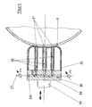
- FIG. 3 shows the view AA according to Figure 2 in an enlarged view. It explains a device for vibration damping, which is pneumatically operated.
- a base 16 is provided, which may be attached directly to the machine bed 1 or to the grinding table 7.
- the base 16 carries a pneumatic double-acting thrust cylinder 17, in which a piston 18 can be acted upon from two sides.
- the piston 18 carries a piston rod 19, to which a mounting plate 20 is located.
- On the mounting plate 20 is the yielding Pad 15 glued or vulcanized.
- the pad may be made of a rubber-like material or a plastic with closed hollow cells, which is thus particularly flexible and adaptable. It is crucial that the outer surface of the resilient pad 15, although elastic, but yet resistant and resistant to abrasion.
- the roller 21 and 22 are compressed air lines through which the thrust cylinder is controlled. He can thus press the resilient pad 15 with precisely adjustable contact force against the roller 6.
- the roller 6, which in this case is a hollow roller is acted on both sides between the grinding wheel 13 and the resilient pad 15. The roller will thus dodge slightly under the contact force of the grinding wheel 13, but occurring transverse vibrations are suppressed by the damping effect of the resilient pad 15.
- the basic position of it yielding pad 15 before the start of the grinding process is adjustable. For example, at the beginning of the contact force zero, so that only under the action of the grinding wheel 13, a depression of the roller 6 takes place in the resilient pad 15.
- a device 14 for vibration damping in which the resilient pad 23 is formed as a hollow body with an elastic outer skin, comparable to the pneumatic tire of vehicles.
- compressed air may be introduced into the interior of the resilient pad 23 with a supply conduit 24, whereby different elasticity characteristics may be achieved.
- FIG. 5 also explains a compliant pad 26 filled with a pressure medium, which is also located on a mounting plate 25 and connected thereto.
- the mounting plate 25 is connected to a supply line 27 for the pressure medium, for the compressed air comes into question in the first place.
- the pressure medium Via an internal, located in the mounting plate 25 channel 28, the pressure medium is introduced into the cavity of the resilient pad 26.
- the resilient pad 26 tubes 30 are passed, which consist of the outer skin of the pad 26 in one piece, but have no connection to the interior of the pad 26.
- the hoses 30 are connected to a channel system 29, which is located in the mounting plate 25 and by a cooling and lubricating medium by means of the hoses 30 is applied directly to the contact surface of the resilient pad 26 on the roller 6.
- the hoses 30 end in outlet openings 31, which are directed directly to the roller 6.
- the outlet openings 31 open on the surface of the roller 6, so that the coolant and lubricant reaches exactly where it is most needed.
- the pressure medium located in the hollow compliant padding can simultaneously serve as coolant and lubricant, separate supply lines for the pressure medium of the pad on the one hand and the cooling and lubricating medium on the other hand are no longer required.
- the constructive implementation which is advantageous in this case is shown in FIG. 6.
- a compliant pad 34 is glued or vulcanized onto a mounting plate 32 again, wherein a supply line 33 via a pressure regulator P21 leads into the interior of the resilient pad 34.
- the resilient pad is provided at its the roller 6 facing end side with a number of outlet openings 35.
- the pressure medium of the pad passes continuously through the outlet openings 35 in the direction of the surface of the roller 6.
- the resilient pad 34 must be continuously updated pressure medium so that the required contact pressure is maintained.
- FIGS. 4 to 6 show how well the inflatable pads conform to the contour of the roller.
- the cooling and lubricating medium between the resilient pad and the roller forms a film, comparable to the water film in the so-called aquaplaning or air cushion in vehicles of the type Hoovercraft vehicles.
- the embodiment according to FIG. 6 is particularly advantageous when working with an air cushion.
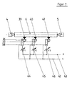
- FIG. 7 shows diagrammatically how the actuation of the devices for vibration damping is to take place when several of these devices are provided along the axial extent of the roller 6 to be ground.
- three means 36, 37, 38 are provided, each of which a resilient pad 39, 40, 41 hires to be ground roller 6.
- the hiring takes place pneumatically, to which each of the devices 36, 37, 38 may have a push cylinder according to the figure 3.
- the oscillation amplitudes in the middle of the roller 6 clamped between the tips 4 and 5 will be greater than in the region of their outer ends, which are closer to the clamping points. Therefore, it is expedient to choose the adjusting force of the device 37 higher than that of the devices 36 and 38.
- a separate pressure control valve 44, 45, 46 is provided, so that the thrust cylinder of each device can obtain the optimum for the vibration damping pneumatic pressure.
- the compressed air supply lines P and return line L are formed together for all facilities.
Landscapes
- Engineering & Computer Science (AREA)
- Mechanical Engineering (AREA)
- Grinding Of Cylindrical And Plane Surfaces (AREA)
- Constituent Portions Of Griding Lathes, Driving, Sensing And Control (AREA)
- Finish Polishing, Edge Sharpening, And Grinding By Specific Grinding Devices (AREA)
- Polishing Bodies And Polishing Tools (AREA)
Claims (28)
- Procédé pour rectifier la circonférence extérieure d'un cylindre (6) rotatif fixé à ses extrémités, à l'aide d'une meule rotative (13), la longueur du cylindre (6) étant un multiple de la largeur de la meule, caractérisé en ce que lors de la rectification au moins un corps rembourré (15, 23, 26, 34, 39, 40, 41) constitué d'un matériau plein élastique ou d'une peau extérieure élastique remplie d'un milieu de pression élastique est appuyé contre le cylindre (6) à rectifier dans la zone circonférentielle opposée à la meule (13).
- Procédé selon la revendication 1, caractérisé en ce qu'il est mis en oeuvre comme rectification longitudinale, la meule rotative (13) et le cylindre rotatif (6) étant déplacés l'un par rapport à l'autre dans le sens longitudinal du cylindre (6) au niveau de la circonférence extérieure de celui-ci.
- Procédé selon la revendication 2, caractérisé en ce que dans une seule fixation le cylindre (6) est successivement dégrossi et fini à la meule avec respectivement une meule CBN (12, 13) à liaison céramique, et l'appui du corps rembourré (6) se produit au moins lors du repassage à la meule.
- Procédé selon l'une quelconque des revendications précédentes, caractérisé en ce que le corps rembourré (15) est appuyé de façon élastique et souple contre le cylindre (6).
- Procédé selon l'une quelconque des revendications précédentes, caractérisé en ce que la force d'appui, avec laquelle le corps rembourré (15) est appuyé contre le cylindre (6), est réglable et peut aussi comporter la valeur zéro avant le début du processus de rectification.
- Procédé selon l'une quelconque des revendications précédentes, caractérisé par un appui pneumatique du corps rembourré (15) contre le cylindre (6).
- Procédé selon l'une quelconque des revendications précédentes, caractérisé en ce que l'appui d'au moins un corps rembourré se produit pendant la rectification contre un point constant dans l'étendue longitudinale du cylindre.
- Procédé selon l'une quelconque des revendications précédentes, caractérisé en ce qu'au moins un corps rembourré (15) et le cylindre (6) se déplacent l'un par rapport à l'autre pendant le processus de rectification parallèlement au sens longitudinal du cylindre (6).
- Procédé selon la revendication 8, caractérisé en ce que le corps rembourré (15) de la meule (13) est déplacé conjointement avec celle-ci par rapport au cylindre (6) radialement, de façon essentiellement opposée.
- Procédé selon l'une quelconque des revendications précédentes, caractérisé en ce que le corps rembourré souple (15, 23, 26, 34) s'adapte, lors de l'appui contre le cylindre (6) à rectifier, au contour cylindrique de celui-ci.
- Procédé selon la revendication 10, caractérisé en ce que l'adaptation s'effectue par l'action, de l'intérieur, d'un milieu de pression, notamment un gaz, sur la peau extérieure du corps rembourré (23, 26, 34), ladite peau souple appuyant contre le cylindre (6) à rectifier.
- Procédé selon l'une quelconque des revendications précédentes, caractérisé en ce qu'un lubrifiant liquide ou gazeux est alimenté au niveau du point d'appui du corps rembourré souple (26, 34) contre le cylindre (6).
- Procédé selon la revendication 12, laquelle se réfère à la revendication 11, caractérisé en ce que le lubrifiant est formé par le milieu de pression du corps rembourré (34) et qu'il est alimenté au niveau du point d'appui via des ouvertures de sortie (35) qui se situent dans la peau extérieure du corps rembourré (34) tournée vers le cylindre (6).
- Procédé selon l'une quelconque des revendications précédentes, caractérisé en ce que le corps rembourré est réglé transversalement par rapport au cylindre à tel point que le cylindre se courbe pendant le processus de rectification, et il se forme en raison de la rectification à l'état final un contour longitudinal du cylindre avec une courbure légèrement concave ou convexe.
- Procédé selon l'une quelconque des revendications précédentes, caractérisé en ce que la force d'appui au moins d'un corps rembourré pendant le processus de rectification est modifiée et/ou réglée à des valeurs différentes pour plusieurs corps rembourrés (39, 40, 41).
- Procédé selon la revendication 15, caractérisé en ce que la force d'appui est modifiée suivant la zone axiale respective du cylindre, par action de la meule et/ou du corps rembourré sur le cylindre.
- Dispositif pour la rectification extérieure de cylindres (6), notamment pour la mise en oeuvre du procédé selon les revendications 1 à 16, avec des organes de serrage et d'entraînement pour serrer le cylindre (6) au niveau de ses extrémités situées côté frontal et pour l'entraînement rotatif du cylindre (6), avec au moins une broche porte-meule (11) entraînant au moins une meule (13), ladite broche pouvant se déplacer dans une direction perpendiculaire à l'axe longitudinal du cylindre (6), moyennant quoi la meule (13) peut être appuyée contre le cylindre (6), avec des entraînements pour le déplacement longitudinal réciproque du cylindre (6) et de la meule (13), et avec au moins un dispositif (14) situé dans la zone circonférentielle du cylindre (6) opposée à la meule (13), caractérisé en ce que par le dispositif (14) un corps rembourré (15, 23, 26, 34, 39, 40, 41) constitué d'un matériau plein élastique ou d'une peau extérieure remplie d'un milieu de pression élastique, peut être également appuyé transversalement par rapport au sens longitudinal du cylindre (6) contre la circonférence de celui-ci.
- Dispositif selon la revendication 17, caractérisé par un dispositif de commande pour régler la force d'appui, avec laquelle le corps rembourré (15) est appuyé contre la circonférence du cylindre à rectifier (6).
- Dispositif selon la revendication 18 avec plusieurs corps rembourrés (39, 40, 41) souples disposés le long du cylindre à rectifier (6), caractérisé en ce que la force d'appui de chaque corps rembourré (39, 40, 41) est réglable individuellement et indépendamment des autres corps rembourrés.
- Dispositif selon la revendication 18 ou 19, caractérisé en ce que le dispositif pour appuyer le corps rembourré souple (15) comprend un cylindre (17) pneumatique de poussée à double action, le corps rembourré (15) étant fixé au niveau de la tige de piston (19) dudit cylindre.
- Dispositif selon la revendication 20 avec plusieurs corps rembourrés (39, 40, 41) disposés le long du cylindre (6) à rectifier, caractérisé en ce qu'une soupape régulatrice de pression (44, 45, 46) est attribuée à chaque cylindre pneumatique de poussée.
- Dispositif selon l'une quelconque des revendications 17 à 21, caractérisé en ce que le milieu de pression est de l'air comprimé.
- Dispositif selon l'une quelconque des revendications 17 à 22, caractérisé en ce que des conduites d'alimentation sont prévues, lesquelles débouchent dans la zone du point d'appui du corps rembourré contre le cylindre et à travers lesquelles est alimenté un lubrifiant au niveau du point d'appui.
- Dispositif selon la revendication 23, caractérisé en ce que sont prévus comme lubrifiants des émulsions de rectification, des réfrigérants lubrifiants synthétiques, des huiles de rectification ou des gaz, en particulier de l'air comprimé.
- Dispositif selon la revendication 23 ou 24, caractérisé en ce que les conduites d'alimentation conduisant le lubrifiant à travers le corps rembourré sont directement guidées en direction du point d'appui du corps rembourré contre le cylindre.
- Dispositif selon la revendication 25, avec un corps rembourré (26) constitué d'une peau extérieure élastique, laquelle est remplie d'un milieu de pression élastique, caractérisé en ce que les conduites d'alimentation conduisant le lubrifiant et traversant le corps rembourré (26) sont conçues comme des tuyaux (30) qui sont d'un tenant avec la peau extérieure élastique du corps rembourré (26), le lubrifiant et le milieu de pression étant séparés l'un de l'autre.
- Dispositif selon la revendication 26, caractérisé en ce que la peau extérieure élastique du rembourrage (34) souple est pourvue au niveau de sa surface d'appui tournée vers le cylindre (6) à rectifier d'une multitude d'ouvertures de sortie, à travers lesquelles le milieu de pression passe pour former un film de refroidissement et de lubrification au niveau du point d'appui.
- Dispositif selon l'une quelconque des revendications 17 à 27, caractérisé en ce qu'une poupée porte-meule (8) dotée de deux broches porte-meule (10, 11) est prévue, lesquelles peuvent être au choix mises en position d'action, la première (10) portant une meule CBN (12) à liaison céramique pour le dégrossissage à la meule et la seconde portant une meule CBN (13) à liaison céramique pour le finissage à la meule, et en ce qu'un accouplement automatique est prévu, par le biais duquel est activé au moins un dispositif destiné à appuyer le corps rembourré souple (15) contre le cylindre à rectifier (6), lorsque la seconde broche porte-meule (11) est mise en position d'action.
Applications Claiming Priority (3)
| Application Number | Priority Date | Filing Date | Title |
|---|---|---|---|
| DE10232394A DE10232394B4 (de) | 2002-07-17 | 2002-07-17 | Verfahren und Vorrichtung zum Schleifen einer rotierenden Walze |
| DE10232394 | 2002-07-17 | ||
| PCT/EP2003/007788 WO2004007145A1 (fr) | 2002-07-17 | 2003-07-17 | Procede et dispositif pour rectifier un cylindre rotatif a l'aide d'un support de lunette fixe elastique |
Publications (2)
| Publication Number | Publication Date |
|---|---|
| EP1521663A1 EP1521663A1 (fr) | 2005-04-13 |
| EP1521663B1 true EP1521663B1 (fr) | 2006-10-25 |
Family
ID=30010119
Family Applications (1)
| Application Number | Title | Priority Date | Filing Date |
|---|---|---|---|
| EP03763887A Expired - Lifetime EP1521663B1 (fr) | 2002-07-17 | 2003-07-17 | Procede et dispositif pour rectifier un cylindre rotatif a l'aide d'un support de lunette fixe elastique |
Country Status (12)
| Country | Link |
|---|---|
| EP (1) | EP1521663B1 (fr) |
| JP (1) | JP4030998B2 (fr) |
| KR (1) | KR101026324B1 (fr) |
| CN (1) | CN100379520C (fr) |
| AT (1) | ATE343453T1 (fr) |
| AU (1) | AU2003254370A1 (fr) |
| BR (1) | BR0312660A (fr) |
| CA (1) | CA2491800C (fr) |
| DE (2) | DE10232394B4 (fr) |
| ES (1) | ES2276116T3 (fr) |
| RU (1) | RU2005104233A (fr) |
| WO (1) | WO2004007145A1 (fr) |
Families Citing this family (31)
| Publication number | Priority date | Publication date | Assignee | Title |
|---|---|---|---|---|
| DE102004012823A1 (de) * | 2004-03-16 | 2005-10-06 | Vollmer Werke Maschinenfabrik Gmbh | Vorrichtung und Verfahren zum Einspannen und Positionieren von Werkstücken unterschiedlicher Länge zwischen zwei Spitzen |
| DE202004021661U1 (de) | 2004-10-27 | 2010-02-04 | Emag Holding Gmbh | Synchronschleifmaschine |
| DE102005024389B4 (de) * | 2005-05-27 | 2016-03-31 | Schaeffler Technologies AG & Co. KG | Verfahren und Vorrichtung zum Schleifen der Außenumfangsfläche eines wellen- bzw. walzenförmigen Werkstückes |
| JP4718298B2 (ja) * | 2005-10-24 | 2011-07-06 | 光洋機械工業株式会社 | 棒状工作物のセンタレス研削方法およびセンタレス研削装置 |
| JP4912695B2 (ja) * | 2006-02-24 | 2012-04-11 | 株式会社シギヤ精機製作所 | 軸状ワークの研削方法及び、ワーク振れ止め装置 |
| CN100441376C (zh) * | 2006-05-10 | 2008-12-10 | 厦门大学 | 气动端面行星运动式金刚石磨具 |
| CN100560295C (zh) * | 2007-06-29 | 2009-11-18 | 上银科技股份有限公司 | 研磨切削颤振的抑制机构 |
| DE102007031512B4 (de) | 2007-07-06 | 2013-01-31 | Erwin Junker Maschinenfabrik Gmbh | Verfahren zur Unterstützung und dynamischen Zentrierung eines rotierenden Werkstücks |
| DE102008010245B4 (de) | 2008-02-20 | 2011-02-10 | Emag Holding Gmbh | Verfahren zum Schleifen wellenförmiger Werkstücke |
| IT1401493B1 (it) * | 2010-07-30 | 2013-07-26 | Tenova Spa | Dispositivo di contrasto per rettifiche di prodotti sostenuti tra centri |
| IT1403602B1 (it) * | 2010-12-22 | 2013-10-31 | Tenova Spa | Metodo per il posizionamento di cilindri operativi su di una macchina rettificatrice e macchina rettificatrice che attua tale metodo |
| CN102335865A (zh) * | 2011-06-22 | 2012-02-01 | 苏州东茂纺织实业有限公司 | 研磨机 |
| CN102490093B (zh) * | 2011-12-02 | 2014-01-08 | 郑州飞机装备有限责任公司 | 用于磨辊中凸度加工的装置 |
| CN102877248B (zh) * | 2012-09-13 | 2015-02-18 | 梁少奇 | 压力辅助防止中边压力不均匀的纺织染压辊 |
| JP6468709B2 (ja) * | 2014-03-20 | 2019-02-13 | 株式会社小松製作所 | ワークレスト装置 |
| CN104139333B (zh) * | 2014-07-11 | 2016-05-18 | 山东金宝电子股份有限公司 | 铜箔表面处理机胶辊胶层的磨削方法及其使用的弧板夹具 |
| CN104191359A (zh) * | 2014-08-04 | 2014-12-10 | 南通五洲轴承有限公司 | 并条、精梳、粗纱、细纱皮辊组合磨夹具 |
| DE102014115183A1 (de) * | 2014-10-17 | 2015-03-05 | SOMATEC, Inh.: Klaus Mayer | Vorrichtung zum Bearbeiten von Werkstücken |
| CN105690227A (zh) * | 2014-11-24 | 2016-06-22 | 宁波江丰电子材料股份有限公司 | 抛光装置和抛光系统 |
| CN104493651B (zh) * | 2014-12-10 | 2017-03-08 | 东莞市天合机电开发有限公司 | 一种新型外圆磨装置 |
| JP6972556B2 (ja) * | 2017-01-10 | 2021-11-24 | 株式会社ジェイテクト | 研削加工装置及び研削加工方法 |
| CN108789137A (zh) * | 2018-06-28 | 2018-11-13 | 盐城市锐克斯研磨科技有限公司 | 一种适用于砂轮机的辅助稳固机构 |
| CN109249311B (zh) * | 2018-10-15 | 2020-06-05 | 东北大学 | 带改进惯容的电控轧辊减振装置 |
| CN110450043B (zh) * | 2019-08-28 | 2020-07-17 | 上海越洲机械制造有限公司 | 一种研磨机构及其使用方法 |
| JP7395973B2 (ja) * | 2019-11-11 | 2023-12-12 | 株式会社ジェイテクト | 研削装置 |
| KR102312031B1 (ko) * | 2019-11-14 | 2021-10-14 | 한전원자력연료 주식회사 | 맨드렐 cnc 시스템 및 방법 |
| CN112847083A (zh) * | 2020-12-26 | 2021-05-28 | 江苏光明环境设备有限公司 | 高效的工件表面涂装生产线 |
| KR102760639B1 (ko) * | 2022-04-29 | 2025-02-03 | 주식회사 동일 | 박판 파이프 성형방법 |
| KR102468331B1 (ko) * | 2022-07-04 | 2022-11-17 | 주식회사 유림원색 | 그라비아 인쇄 롤러 연마 방법 및 장치 |
| KR102543012B1 (ko) * | 2023-02-17 | 2023-06-13 | 김학규 | 롤러 연마 시스템 |
| JP7432082B1 (ja) | 2023-05-18 | 2024-02-16 | 知之 深瀬 | 研削盤のワーク支持装置 |
Family Cites Families (6)
| Publication number | Priority date | Publication date | Assignee | Title |
|---|---|---|---|---|
| GB1160276A (en) * | 1965-12-28 | 1969-08-06 | Hobson Ltd H M | Improvements in or relating to Work Steadies |
| US3425168A (en) * | 1966-08-19 | 1969-02-04 | Babcock & Wilcox Co | Work follower rests |
| DE2163084A1 (de) * | 1971-12-18 | 1973-06-20 | Fortuna Werke Maschf Ag | Anordnung an setzstockpinolen |
| JP3100640B2 (ja) * | 1990-12-07 | 2000-10-16 | バンドー化学株式会社 | ゴム状弾性を有するロールの研削方法 |
| JPH07178665A (ja) * | 1993-12-21 | 1995-07-18 | Honda Motor Co Ltd | 研削盤 |
| DE19857359B4 (de) * | 1998-12-11 | 2005-09-15 | Erwin Junker Maschinenfabrik Gmbh | Verfahren und Vorrichtung zum Bearbeiten von Werkstücken mit dünnwandigen Bereichen, die zentrische Formabweichungen aufweisen |
-
2002
- 2002-07-17 DE DE10232394A patent/DE10232394B4/de not_active Expired - Fee Related
-
2003
- 2003-07-17 WO PCT/EP2003/007788 patent/WO2004007145A1/fr not_active Ceased
- 2003-07-17 CA CA2491800A patent/CA2491800C/fr not_active Expired - Fee Related
- 2003-07-17 EP EP03763887A patent/EP1521663B1/fr not_active Expired - Lifetime
- 2003-07-17 RU RU2005104233/02A patent/RU2005104233A/ru not_active Application Discontinuation
- 2003-07-17 CN CNB038168138A patent/CN100379520C/zh not_active Expired - Fee Related
- 2003-07-17 KR KR1020047021543A patent/KR101026324B1/ko not_active Expired - Fee Related
- 2003-07-17 BR BR0312660-9A patent/BR0312660A/pt not_active Application Discontinuation
- 2003-07-17 DE DE50305509T patent/DE50305509D1/de not_active Expired - Lifetime
- 2003-07-17 ES ES03763887T patent/ES2276116T3/es not_active Expired - Lifetime
- 2003-07-17 JP JP2004520664A patent/JP4030998B2/ja not_active Expired - Fee Related
- 2003-07-17 AT AT03763887T patent/ATE343453T1/de not_active IP Right Cessation
- 2003-07-17 AU AU2003254370A patent/AU2003254370A1/en not_active Abandoned
Also Published As
| Publication number | Publication date |
|---|---|
| DE50305509D1 (de) | 2006-12-07 |
| AU2003254370A1 (en) | 2004-02-02 |
| RU2005104233A (ru) | 2005-10-10 |
| BR0312660A (pt) | 2005-04-26 |
| KR101026324B1 (ko) | 2011-03-31 |
| ATE343453T1 (de) | 2006-11-15 |
| EP1521663A1 (fr) | 2005-04-13 |
| KR20050019813A (ko) | 2005-03-03 |
| DE10232394A1 (de) | 2004-02-26 |
| CA2491800A1 (fr) | 2004-01-22 |
| CA2491800C (fr) | 2011-02-22 |
| JP4030998B2 (ja) | 2008-01-09 |
| ES2276116T3 (es) | 2007-06-16 |
| CN100379520C (zh) | 2008-04-09 |
| CN1668421A (zh) | 2005-09-14 |
| DE10232394B4 (de) | 2004-07-22 |
| JP2005537140A (ja) | 2005-12-08 |
| WO2004007145A1 (fr) | 2004-01-22 |
Similar Documents
| Publication | Publication Date | Title |
|---|---|---|
| EP1521663B1 (fr) | Procede et dispositif pour rectifier un cylindre rotatif a l'aide d'un support de lunette fixe elastique | |
| DE10234707B4 (de) | Verfahren und Vorrichtung zum Schleifen eines rotationssymmetrischen Maschinenbauteils | |
| DE102009024209B4 (de) | Verfahren und vorrichtung zum mehrlagenschleifen von werkstücken | |
| DE4426452C1 (de) | Verfahren und Maschine zum Schleifen von Nocken mit konkaven Flanken | |
| EP2150377B1 (fr) | Usinage sans vibrations de mandrins à pas de pèlerin | |
| DE19634839A1 (de) | Feinstbearbeitung mit Vibrationskopf | |
| DE102015206565A1 (de) | VERFAHREN UND SYSTEM ZUM AUßENSCHLEIFEN VON WELLENTEILEN ZWISCHEN SPITZEN | |
| DE19751750B4 (de) | Verfahren und Vorrichtung zum Herstellen von polierbaren, optischen Linsen aus Linsenrohlingen | |
| EP3135433A2 (fr) | Unite de traitement de surfaces circonferentielles, machine-outil et procede de fonctionnement | |
| DE2718339A1 (de) | Vorrichtung und verfahren zur schleifscheibenabrichtung | |
| DE4107462C2 (de) | Werkzeugmaschine zur spanabhebenden Bearbeitung von Werkstücken | |
| EP0359304B1 (fr) | Procédé et dispositif de meulage de copiage de surfaces cylindriques ou sphériques | |
| DE2714222A1 (de) | Verfahren und vorrichtung zur feinbearbeitung der anlaufbunde fuer waelzkoerper von waelzlagern | |
| DE102007050470A1 (de) | Verfahren zum Herstellen von optisch aktiven Oberflächen durch Polieren von vorgeschliffenen Linsen und eine Vorrichtung zur Durchführung des Verfahrens | |
| DE2639058C2 (de) | Einrichtung zum Formen und Schärfen einer drehangetriebenen Schleifscheibe aus kubischem Bornitrid | |
| EP1330336B1 (fr) | Rectifieuse cylindrique sans centres | |
| CH628695A5 (en) | Mobile rail-grinding machine | |
| EP4178761B1 (fr) | Tête de meulage pour l'usinage de pièces à usiner | |
| EP3581325A1 (fr) | Procédé et dispositif de traitement de la surface de roulement de roues pour véhicules sur rails | |
| DE4419366A1 (de) | Finishmaschine | |
| DE4409060C3 (de) | Vorrichtung zum Nachschleifen eingebauter Walzen | |
| DE3437682C2 (de) | Vorrichtung zum Abrichten eines Doppelkegelschleifkörpers | |
| DE2458366A1 (de) | Schleifverfahren sowie vorrichtung zur durchfuehrung dieses verfahrens | |
| DE3639264C2 (de) | Vorrichtung zum Kopierschleifen und Glätten von zylindrischen und sphärischen Oberflächen | |
| DE3829648A1 (de) | Verfahren zur herstellung von nuten in zylindrischen walzen und schleifmaschine zur durchfuehrung des verfahrens |
Legal Events
| Date | Code | Title | Description |
|---|---|---|---|
| PUAI | Public reference made under article 153(3) epc to a published international application that has entered the european phase |
Free format text: ORIGINAL CODE: 0009012 |
|
| 17P | Request for examination filed |
Effective date: 20041130 |
|
| AK | Designated contracting states |
Kind code of ref document: A1 Designated state(s): AT BE BG CH CY CZ DE DK EE ES FI FR GB GR HU IE IT LI LU MC NL PT RO SE SI SK TR |
|
| AX | Request for extension of the european patent |
Extension state: AL LT LV MK |
|
| DAX | Request for extension of the european patent (deleted) | ||
| GRAP | Despatch of communication of intention to grant a patent |
Free format text: ORIGINAL CODE: EPIDOSNIGR1 |
|
| GRAS | Grant fee paid |
Free format text: ORIGINAL CODE: EPIDOSNIGR3 |
|
| GRAA | (expected) grant |
Free format text: ORIGINAL CODE: 0009210 |
|
| AK | Designated contracting states |
Kind code of ref document: B1 Designated state(s): AT BE BG CH CY CZ DE DK EE ES FI FR GB GR HU IE IT LI LU MC NL PT RO SE SI SK TR |
|
| PG25 | Lapsed in a contracting state [announced via postgrant information from national office to epo] |
Ref country code: SK Free format text: LAPSE BECAUSE OF FAILURE TO SUBMIT A TRANSLATION OF THE DESCRIPTION OR TO PAY THE FEE WITHIN THE PRESCRIBED TIME-LIMIT Effective date: 20061025 Ref country code: RO Free format text: LAPSE BECAUSE OF FAILURE TO SUBMIT A TRANSLATION OF THE DESCRIPTION OR TO PAY THE FEE WITHIN THE PRESCRIBED TIME-LIMIT Effective date: 20061025 Ref country code: SI Free format text: LAPSE BECAUSE OF FAILURE TO SUBMIT A TRANSLATION OF THE DESCRIPTION OR TO PAY THE FEE WITHIN THE PRESCRIBED TIME-LIMIT Effective date: 20061025 Ref country code: FI Free format text: LAPSE BECAUSE OF FAILURE TO SUBMIT A TRANSLATION OF THE DESCRIPTION OR TO PAY THE FEE WITHIN THE PRESCRIBED TIME-LIMIT Effective date: 20061025 Ref country code: NL Free format text: LAPSE BECAUSE OF FAILURE TO SUBMIT A TRANSLATION OF THE DESCRIPTION OR TO PAY THE FEE WITHIN THE PRESCRIBED TIME-LIMIT Effective date: 20061025 Ref country code: IE Free format text: LAPSE BECAUSE OF FAILURE TO SUBMIT A TRANSLATION OF THE DESCRIPTION OR TO PAY THE FEE WITHIN THE PRESCRIBED TIME-LIMIT Effective date: 20061025 |
|
| REG | Reference to a national code |
Ref country code: GB Ref legal event code: FG4D Free format text: NOT ENGLISH |
|
| REG | Reference to a national code |
Ref country code: CH Ref legal event code: EP |
|
| REG | Reference to a national code |
Ref country code: IE Ref legal event code: FG4D Free format text: LANGUAGE OF EP DOCUMENT: GERMAN |
|
| REF | Corresponds to: |
Ref document number: 50305509 Country of ref document: DE Date of ref document: 20061207 Kind code of ref document: P |
|
| PG25 | Lapsed in a contracting state [announced via postgrant information from national office to epo] |
Ref country code: SE Free format text: LAPSE BECAUSE OF FAILURE TO SUBMIT A TRANSLATION OF THE DESCRIPTION OR TO PAY THE FEE WITHIN THE PRESCRIBED TIME-LIMIT Effective date: 20070125 Ref country code: DK Free format text: LAPSE BECAUSE OF FAILURE TO SUBMIT A TRANSLATION OF THE DESCRIPTION OR TO PAY THE FEE WITHIN THE PRESCRIBED TIME-LIMIT Effective date: 20070125 Ref country code: BG Free format text: LAPSE BECAUSE OF FAILURE TO SUBMIT A TRANSLATION OF THE DESCRIPTION OR TO PAY THE FEE WITHIN THE PRESCRIBED TIME-LIMIT Effective date: 20070125 |
|
| GBT | Gb: translation of ep patent filed (gb section 77(6)(a)/1977) |
Effective date: 20070117 |
|
| PG25 | Lapsed in a contracting state [announced via postgrant information from national office to epo] |
Ref country code: PT Free format text: LAPSE BECAUSE OF FAILURE TO SUBMIT A TRANSLATION OF THE DESCRIPTION OR TO PAY THE FEE WITHIN THE PRESCRIBED TIME-LIMIT Effective date: 20070326 |
|
| NLV1 | Nl: lapsed or annulled due to failure to fulfill the requirements of art. 29p and 29m of the patents act | ||
| ET | Fr: translation filed | ||
| REG | Reference to a national code |
Ref country code: ES Ref legal event code: FG2A Ref document number: 2276116 Country of ref document: ES Kind code of ref document: T3 |
|
| REG | Reference to a national code |
Ref country code: IE Ref legal event code: FD4D |
|
| PLBE | No opposition filed within time limit |
Free format text: ORIGINAL CODE: 0009261 |
|
| STAA | Information on the status of an ep patent application or granted ep patent |
Free format text: STATUS: NO OPPOSITION FILED WITHIN TIME LIMIT |
|
| 26N | No opposition filed |
Effective date: 20070726 |
|
| BERE | Be: lapsed |
Owner name: ERWIN JUNKER MASCHINENFABRIK G.M.B.H. Effective date: 20070731 |
|
| REG | Reference to a national code |
Ref country code: CH Ref legal event code: PL |
|
| PG25 | Lapsed in a contracting state [announced via postgrant information from national office to epo] |
Ref country code: MC Free format text: LAPSE BECAUSE OF NON-PAYMENT OF DUE FEES Effective date: 20070731 Ref country code: CH Free format text: LAPSE BECAUSE OF NON-PAYMENT OF DUE FEES Effective date: 20070731 Ref country code: LI Free format text: LAPSE BECAUSE OF NON-PAYMENT OF DUE FEES Effective date: 20070731 Ref country code: GR Free format text: LAPSE BECAUSE OF FAILURE TO SUBMIT A TRANSLATION OF THE DESCRIPTION OR TO PAY THE FEE WITHIN THE PRESCRIBED TIME-LIMIT Effective date: 20070126 |
|
| PG25 | Lapsed in a contracting state [announced via postgrant information from national office to epo] |
Ref country code: BE Free format text: LAPSE BECAUSE OF NON-PAYMENT OF DUE FEES Effective date: 20070731 |
|
| PG25 | Lapsed in a contracting state [announced via postgrant information from national office to epo] |
Ref country code: AT Free format text: LAPSE BECAUSE OF NON-PAYMENT OF DUE FEES Effective date: 20070717 |
|
| PG25 | Lapsed in a contracting state [announced via postgrant information from national office to epo] |
Ref country code: EE Free format text: LAPSE BECAUSE OF FAILURE TO SUBMIT A TRANSLATION OF THE DESCRIPTION OR TO PAY THE FEE WITHIN THE PRESCRIBED TIME-LIMIT Effective date: 20061025 |
|
| PG25 | Lapsed in a contracting state [announced via postgrant information from national office to epo] |
Ref country code: LU Free format text: LAPSE BECAUSE OF NON-PAYMENT OF DUE FEES Effective date: 20070717 Ref country code: CY Free format text: LAPSE BECAUSE OF FAILURE TO SUBMIT A TRANSLATION OF THE DESCRIPTION OR TO PAY THE FEE WITHIN THE PRESCRIBED TIME-LIMIT Effective date: 20061025 |
|
| PG25 | Lapsed in a contracting state [announced via postgrant information from national office to epo] |
Ref country code: HU Free format text: LAPSE BECAUSE OF FAILURE TO SUBMIT A TRANSLATION OF THE DESCRIPTION OR TO PAY THE FEE WITHIN THE PRESCRIBED TIME-LIMIT Effective date: 20070426 Ref country code: TR Free format text: LAPSE BECAUSE OF FAILURE TO SUBMIT A TRANSLATION OF THE DESCRIPTION OR TO PAY THE FEE WITHIN THE PRESCRIBED TIME-LIMIT Effective date: 20061025 |
|
| REG | Reference to a national code |
Ref country code: FR Ref legal event code: PLFP Year of fee payment: 13 |
|
| PGFP | Annual fee paid to national office [announced via postgrant information from national office to epo] |
Ref country code: GB Payment date: 20150727 Year of fee payment: 13 Ref country code: DE Payment date: 20150730 Year of fee payment: 13 Ref country code: ES Payment date: 20150827 Year of fee payment: 13 Ref country code: CZ Payment date: 20150716 Year of fee payment: 13 |
|
| PGFP | Annual fee paid to national office [announced via postgrant information from national office to epo] |
Ref country code: FR Payment date: 20150630 Year of fee payment: 13 |
|
| PGFP | Annual fee paid to national office [announced via postgrant information from national office to epo] |
Ref country code: IT Payment date: 20150729 Year of fee payment: 13 |
|
| REG | Reference to a national code |
Ref country code: DE Ref legal event code: R119 Ref document number: 50305509 Country of ref document: DE |
|
| GBPC | Gb: european patent ceased through non-payment of renewal fee |
Effective date: 20160717 |
|
| PG25 | Lapsed in a contracting state [announced via postgrant information from national office to epo] |
Ref country code: FR Free format text: LAPSE BECAUSE OF NON-PAYMENT OF DUE FEES Effective date: 20160801 Ref country code: DE Free format text: LAPSE BECAUSE OF NON-PAYMENT OF DUE FEES Effective date: 20170201 |
|
| REG | Reference to a national code |
Ref country code: FR Ref legal event code: ST Effective date: 20170331 |
|
| PG25 | Lapsed in a contracting state [announced via postgrant information from national office to epo] |
Ref country code: CZ Free format text: LAPSE BECAUSE OF NON-PAYMENT OF DUE FEES Effective date: 20160717 Ref country code: GB Free format text: LAPSE BECAUSE OF NON-PAYMENT OF DUE FEES Effective date: 20160717 |
|
| PG25 | Lapsed in a contracting state [announced via postgrant information from national office to epo] |
Ref country code: IT Free format text: LAPSE BECAUSE OF NON-PAYMENT OF DUE FEES Effective date: 20160717 |
|
| PG25 | Lapsed in a contracting state [announced via postgrant information from national office to epo] |
Ref country code: ES Free format text: LAPSE BECAUSE OF NON-PAYMENT OF DUE FEES Effective date: 20160718 |
|
| REG | Reference to a national code |
Ref country code: ES Ref legal event code: FD2A Effective date: 20181129 |