EP1521663B1 - Method and device for grinding a rotating roller using an elastic steady-rest support - Google Patents
Method and device for grinding a rotating roller using an elastic steady-rest support Download PDFInfo
- Publication number
- EP1521663B1 EP1521663B1 EP03763887A EP03763887A EP1521663B1 EP 1521663 B1 EP1521663 B1 EP 1521663B1 EP 03763887 A EP03763887 A EP 03763887A EP 03763887 A EP03763887 A EP 03763887A EP 1521663 B1 EP1521663 B1 EP 1521663B1
- Authority
- EP
- European Patent Office
- Prior art keywords
- roller
- grinding
- padding body
- contact
- grinding wheel
- Prior art date
- Legal status (The legal status is an assumption and is not a legal conclusion. Google has not performed a legal analysis and makes no representation as to the accuracy of the status listed.)
- Expired - Lifetime
Links
- 238000000034 method Methods 0.000 title claims description 53
- 239000000314 lubricant Substances 0.000 claims description 21
- 239000007788 liquid Substances 0.000 claims description 8
- 238000001816 cooling Methods 0.000 claims description 5
- 230000001050 lubricating effect Effects 0.000 claims description 5
- 230000002093 peripheral effect Effects 0.000 claims description 5
- 230000006978 adaptation Effects 0.000 claims description 2
- 230000008878 coupling Effects 0.000 claims description 2
- 238000010168 coupling process Methods 0.000 claims description 2
- 238000005859 coupling reaction Methods 0.000 claims description 2
- 238000006073 displacement reaction Methods 0.000 claims description 2
- 239000000839 emulsion Substances 0.000 claims description 2
- 239000003921 oil Substances 0.000 claims description 2
- 239000013013 elastic material Substances 0.000 claims 2
- 239000007787 solid Substances 0.000 claims 2
- 230000003213 activating effect Effects 0.000 claims 1
- 239000005068 cooling lubricant Substances 0.000 claims 1
- 238000013016 damping Methods 0.000 abstract description 13
- 230000001172 regenerating effect Effects 0.000 abstract description 6
- 239000011343 solid material Substances 0.000 abstract description 3
- 230000008569 process Effects 0.000 description 16
- 239000002826 coolant Substances 0.000 description 7
- 241000951498 Brachypteraciidae Species 0.000 description 3
- 229910000831 Steel Inorganic materials 0.000 description 3
- 230000000694 effects Effects 0.000 description 3
- 230000002706 hydrostatic effect Effects 0.000 description 3
- 239000002184 metal Substances 0.000 description 3
- 239000010959 steel Substances 0.000 description 3
- 238000005299 abrasion Methods 0.000 description 2
- 239000000919 ceramic Substances 0.000 description 2
- 230000008859 change Effects 0.000 description 2
- 229910052593 corundum Inorganic materials 0.000 description 2
- 239000010431 corundum Substances 0.000 description 2
- 238000003754 machining Methods 0.000 description 2
- 238000004519 manufacturing process Methods 0.000 description 2
- 239000000463 material Substances 0.000 description 2
- 230000010355 oscillation Effects 0.000 description 2
- 239000004033 plastic Substances 0.000 description 2
- 238000012545 processing Methods 0.000 description 2
- 230000009471 action Effects 0.000 description 1
- 230000004323 axial length Effects 0.000 description 1
- 210000001217 buttock Anatomy 0.000 description 1
- 238000010276 construction Methods 0.000 description 1
- 238000013461 design Methods 0.000 description 1
- 238000011161 development Methods 0.000 description 1
- 230000018109 developmental process Effects 0.000 description 1
- 238000010586 diagram Methods 0.000 description 1
- 238000005516 engineering process Methods 0.000 description 1
- 230000005284 excitation Effects 0.000 description 1
- 238000002474 experimental method Methods 0.000 description 1
- 239000006260 foam Substances 0.000 description 1
- 239000010687 lubricating oil Substances 0.000 description 1
- 238000005461 lubrication Methods 0.000 description 1
- 238000010327 methods by industry Methods 0.000 description 1
- 230000000284 resting effect Effects 0.000 description 1
- 238000004904 shortening Methods 0.000 description 1
- 238000003860 storage Methods 0.000 description 1
- 238000012549 training Methods 0.000 description 1
- XLYOFNOQVPJJNP-UHFFFAOYSA-N water Substances O XLYOFNOQVPJJNP-UHFFFAOYSA-N 0.000 description 1
Images


Classifications
-
- B—PERFORMING OPERATIONS; TRANSPORTING
- B24—GRINDING; POLISHING
- B24B—MACHINES, DEVICES, OR PROCESSES FOR GRINDING OR POLISHING; DRESSING OR CONDITIONING OF ABRADING SURFACES; FEEDING OF GRINDING, POLISHING, OR LAPPING AGENTS
- B24B5/00—Machines or devices designed for grinding surfaces of revolution on work, including those which also grind adjacent plane surfaces; Accessories therefor
- B24B5/02—Machines or devices designed for grinding surfaces of revolution on work, including those which also grind adjacent plane surfaces; Accessories therefor involving centres or chucks for holding work
- B24B5/04—Machines or devices designed for grinding surfaces of revolution on work, including those which also grind adjacent plane surfaces; Accessories therefor involving centres or chucks for holding work for grinding cylindrical surfaces externally
-
- B—PERFORMING OPERATIONS; TRANSPORTING
- B24—GRINDING; POLISHING
- B24B—MACHINES, DEVICES, OR PROCESSES FOR GRINDING OR POLISHING; DRESSING OR CONDITIONING OF ABRADING SURFACES; FEEDING OF GRINDING, POLISHING, OR LAPPING AGENTS
- B24B41/00—Component parts such as frames, beds, carriages, headstocks
- B24B41/007—Weight compensation; Temperature compensation; Vibration damping
-
- B—PERFORMING OPERATIONS; TRANSPORTING
- B24—GRINDING; POLISHING
- B24B—MACHINES, DEVICES, OR PROCESSES FOR GRINDING OR POLISHING; DRESSING OR CONDITIONING OF ABRADING SURFACES; FEEDING OF GRINDING, POLISHING, OR LAPPING AGENTS
- B24B41/00—Component parts such as frames, beds, carriages, headstocks
- B24B41/06—Work supports, e.g. adjustable steadies
- B24B41/065—Steady rests
Definitions
- the invention relates to a method and a device according to the preamble of claim 1 or 17.
- a method and such a device is known from DE 16 27 998 A.
- slender, elongate rolls are required which rotate during operation, are partly driven and often have to be heated or cooled from the inside.
- Such rolls may for example have a length of about 1000 mm and a diameter of 85 mm.
- the rollers are also often tubular with a small wall thickness down to 1 mm. High demands are placed on the surface quality of these rolls and on their dimensional accuracy. The grinding of such rolls to the finished size and the required surface finish therefore places high demands on the expert's skill.
- a known disadvantageous aspect of external grinding of rollers is that they deflect laterally when the grinding wheel acts on its peripheral surface. This can lead to the finished roll deviating from the cylindrical shape.
- the roller gets into self-excited transverse vibrations, the so-called regenerative rattling.
- the result of this regenerative rattling are chatter marks on the peripheral surface of the roll, which mean a reduced surface quality and render the resulting roll useless for many applications.
- a well-known from practice in the method of the type mentioned is that the roller is first pre-ground in Einstech psychologist with an existing corundum grinding wheel. For this purpose, the roller is processed to a roughing in the way that the grinding wheel is pierced several times side by side until the whole length of the roller is pre-ground to this degree. Subsequently, the same grinding wheel is dressed and then fine or finish ground.
- the finish grinding is carried out by longitudinal grinding, wherein the rotating grinding wheel and the rotating roller are moved in the longitudinal direction of the roller at its outer periphery relative to each other.
- With a length of the roller of, for example, 1000 mm grinding wheels with a width of, for example, 100 mm are used for this purpose.
- the disadvantage of the known method is that the grinding wheels consisting of corundum often have to be dressed. This may also be required during a single finish grinding operation. Overall, the known grinding process is very tedious.
- a follower buttstock for supporting cylindrical workpieces in a grinding machine which forms a hydrostatic half bearing.
- the rotating workpiece to be ground thus rests on a liquid film, which must be constantly renewed.
- a liquid flow is continuously fed to the hydrostatic half bearing.
- the liquid can be a coolant that is required anyway during grinding.
- the invention is therefore an object of the invention to provide a method of the type mentioned, which allows the use of CBN grinding wheels and significantly reduced processing times, while still leading to rollers of high dimensional accuracy and surface quality.
- the pad body is made in the circumferential area opposite the grinding wheel to the roller to be ground, the transverse vibrations of the roller as well as resulting from the grinding wheel vibrations are successfully damped. The regenerative rattle does not occur, and thus the dreaded chatter marks are no longer recorded.
- the upholstery body does not lead to any running marks which mean reduced surface quality and can be recognized immediately by the person skilled in the art.
- the requirement of the circumference area opposite the grinding wheel means that the cushion body, for instance, is to be mounted radially opposite the grinding wheel on the opposite side of the roller.
- the inventive method as longitudinal grinding, wherein the rotating grinding wheel 13 and the rotating roller 6 are moved in the longitudinal direction of the roller 6 at the outer periphery relative to each other.
- the roller which is mounted in tips and driven by this or by a driver for rotation, are passed on a grinding table on the rotating grinding wheel.
- the continuous longitudinal grinding better corresponds to an automated procedure than the piercing grinding required in paragraphs; moreover, there is no problem of the grinding marks at the crossing points.
- a particularly advantageous embodiment of the method according to the invention is therefore that the roller 6 in one single clamping successively with one ceramic bonded CBN grinding wheel 12, 13 is pre-ground and finished and the employment of the cushion body 6 at least during regrinding.
- the following advantageous embodiments of the method according to the invention relate to how the cushion body - hereinafter collectively referred to as a "resilient pad" - hired to the roller and optionally moved towards her.
- the pad 15 is employed elastically yielding to the roller 6.
- this can be done by a linear guide with a positioning spring whose tension is adjustable.
- the employment by a pressure medium, but also an electronically controlled employment by electric motors is conceivable.
- the contact force with which the resilient pad 15 is made to the roller 6, is adjustable and can also be zero before the start of the grinding process.
- the employment of the at least one resilient pad is because the roller bends under the influence of the machining forces of the grinding wheel in the direction of the pad.
- a control of the adjusting force which can be controlled particularly well from a technical point of view, results from a pneumatic adjustment of the yielding cushion 15 to the roller 6.
- the simplest method of the invention according to another embodiment is carried out in that the employment of the at least one resilient pad during grinding takes place at a constant point in the longitudinal extent of the roller. For example, if the roller is mounted between tips and the grinding wheel is guided past the outer circumference of the roller in the longitudinal direction, it is preferable to arrange the resilient pad substantially in the axial center of the roller, because there the strongest transverse vibrations occur.
- the resilient pad 15, 23, 26, 34 adapts to the cylindrical contour when it is being set against the roller 6 to be ground.
- the adaptation can be carried out particularly advantageously in that a pressure medium, in particular a gas, acts on a flexible outer skin of the pad 23, 26, 34 resting against the roller to be ground 6 from the inside. In this way, the pad is inflated like a balloon that adapts softly to an obstacle.
- the contact point of the resilient pad 23, 26, 34 is supplied to the roller 6, a liquid or gaseous lubricant.
- the associated method can be particularly easily designed in such a way that the lubricant is formed by the pressure medium of the pad 34 and the contact point is supplied through outlet openings 35, which are in the roller 6 facing outer skin of the pad 34.
- a certain longitudinal contour of the roller during grinding can be achieved by setting the compliant cushion across the roller so that the roller deflects during the grinding process and by grinding in the final state a longitudinal contour of the roller with a slight concave or convex curvature comes.
- the roller here assumes a desired deflection during grinding, without transverse vibrations occurring. If the compliant pad has a certain distance from its outer periphery when the roller is at rest, the roller will deflect under the influence of the wheel until it touches the pad. But also the setting of a bias voltage is possible, in which case the roller is bulged in the direction of the grinding wheel. With proper control of the corresponding grinding processes arise rollers with an axial longitudinal contour, which runs in the desired manner concave or convex.
- the resulting transverse vibrations also change, depending on in which axial region of the roll the grinding wheel is currently located. Therefore, it is advantageous for fine tuning of the grinding process when the contact force of the at least one resilient pad is changed during the grinding process and / or is set to different values for a plurality of pads 39, 40, 41.
- the change in the contact force is carried out in accordance with the respective axial region of the roller, in which the grinding wheel and / or the pad just act on the roller. The required values can be quickly determined by calculations or practical experiments.
- the invention also relates to a device for external grinding of rollers, in particular for carrying out the method according to the invention according to the above-cited claims.
- a device for external grinding of rollers in particular for carrying out the method according to the invention according to the above-cited claims.
- the invention provided according to claim 17 is thus an apparatus for grinding outer rollers 6, in particular for carrying out the method according to claims 1 to 16, with clamping and Antriebsgliedem for clamping the roller 6 at its front ends and for the rotary drive of the roller 6, with at least a grinding wheel 13 driving grinding spindle 11 which is movable in a direction transverse to the longitudinal axis of the roller 6, whereby the grinding wheel 13 against the roller 6 can be adjusted, with drives for mutual longitudinal displacement of roller 6 and grinding wheel 13 and at least one in the periphery of the roller 6 located opposite the grinding wheel 13 device 14 through which a cushion body 15, 23, 26, 34, 39, 40, 41 of a resilient solid material or an elastic, filled with an elastic pressure medium outer skin also transverse to the longitudinal direction of the
- the means for adjusting the cushion body may for example be provided on the machine bed or on a grinding table which also carries the roll to be ground.
- the hiring can be done mechanically, electrically or by a pressure medium.
- the following embodiments relate to how the contact force can be constructively advantageous and selectively applied in height.
- a control arrangement for adjusting the adjusting force is provided, with which the resilient pad 15 is employed against the circumference of the roller 6 to be ground.
- each pad 39, 40, 41 can be adjusted individually and independently of the other pads.
- the device for adjusting the resilient pad 15 comprises a double-acting pneumatic push cylinder 17, on the piston rod 19, the pad 15 is attached. If a plurality of flexible pads 39, 40, 41 arranged along the roller 6 to be ground are present, then each pneumatic push cylinder is assigned its own pressure control valve 44, 45, 46. In this way, a perfect pneumatic control is ensured, with which the vibrations are successfully damped at several points of the axial extent of the roller.
- the resilient pad 15 is formed by a body of a resilient solid material.
- a high-quality, with closed cells trained foam plastic which has an abrasion-resistant surface or is provided with it, can already fulfill this task well. It will already adapt to a certain extent to the outer contour of the roller and thus successfully dampen the vibrations.
- the resilient pad 23 is formed by a hollow body of an elastic outer skin in which a pressure medium is located.
- This pressure medium may be a gas, preferably compressed air.
- a pressurized hollow body is adapted to the outer contour of the roller particularly well suited, the effect can still be controlled by the fact that the internal pressure is optimally adjusted depending on the grinding process to be performed.
- lubrication and cooling agent is supplied to the contact point.
- supply lines are provided according to an advantageous embodiment, which open in the region of the contact point of the resilient pad on the roller and through which the contact point, a lubricant is supplied.
- Suitable lubricants are the grinding emulsions, synthetic coolants and grinding oils customary in grinding technology. But also compressed air can be considered. If the supply lines leading the lubricant are guided through the resilient pad directly to the contact point of the pad on the roller, then the lubricant is located directly where it can act most strongly.
- a film forms between the roller and the compliant pad, which corresponds to the hydroplaning of the automobile tire and is particularly effective. If lubricated with compressed air, so an air cushion can be formed, as it is known from hovercraft. It must be emphasized that the lubricant film or air cushion effectively reduces the friction losses during grinding without thereby reducing the effect of vibration damping.
- a structurally particularly effective solution consists in that the supply lines leading through the flexible cushion 26 are designed as hoses 30 which are made in one piece with the elastic outer skin of the pad 26, the lubricant and the pressure medium being separated from one another.
- the pressure medium of the pad itself as a coolant in question it is structurally particularly simple that the elastic outer skin of the resilient pad 34 at its facing the roller to be grounded 6 contact surface with a variety is provided by outlet openings through which passes the pressure medium to form the cooling and lubricating film to the contact point.
- this training must thus constantly pressure medium from the resilient pad to the contact point to pass outwards. It is a constant supply of the pressure medium required, which, however, is easy to control by pressure control valves.
- the solution can be perfected even further by the fact that the pneumatic control of the push cylinder, on whose piston rod the yielding cushion is located, is also included in the process.
- a wheel spindle 8 with two grinding spindles 10, 11 is provided, which can be brought selectively into operative position and of which the first 10 carries a ceramically bonded CBN grinding wheel 12 for rough grinding and the second a ceramically bonded CBN grinding wheel 13 for finish grinding, wherein an automatic coupling is provided by which the at least one means for adjusting the resilient pad 15 to the To be ground roller 6 is activated when the second grinding spindle 11 is brought into operative position.
- the device according to the invention is prepared in this way for automation, which is often desired in modern mass production on production lines.
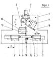
- FIG. 1 is a schematic representation of a conventional cylindrical grinding machine for external grinding of cylindrical parts.
- a machine bed 1 can be seen, on which a workpiece headstock 2 and a tailstock 3 are located.
- Workpiece headstock 2 and tailstock 3 are mutually adjustable in the axial direction, so that by means of the tips 4 and 5 located on them, the roller 6 to be ground can be clamped and driven for rotation.
- the roller can also be driven by drivers, which are customary and therefore not shown separately here.
- the workpiece headstock 2 and the tailstock 3 are located on a grinding table 7, which can be moved as a whole in the Z direction.
- the grinding headstock carries a first grinding spindle 10 and a second grinding spindle 11.
- the first grinding spindle 10 carries a first grinding wheel 12, which serves for roughing or roughing
- the second grinding spindle 11 carries a second grinding wheel 13 intended for finish grinding or finishing.
- the wheelhead 8 By pivoting about the vertical pivot axis 9, the wheelhead 8 moves in the direction of arrow B, so that either the grinding wheel 12 ( Figure 1) or the second grinding wheel 13 ( Figure 2) can be brought into operative position.
- the entire wheelhead 8 can be moved numerically controlled in the X direction, whereby the grinding wheel, which is in the active position in each case, comes into contact with the roller 6 to be grounded in a controlled manner.
- the axial length of the roller 6 to be ground is a multiple of the grinding wheel width, so that for grinding during so-called longitudinal grinding, the grinding wheel and the roller to be grounded must be moved past each other in the axial direction.
- the roller 6 located on the grinding carriage can be moved past the grinding wheel.
- the roller to be ground is fixed in the axial direction, while the wheel head is moved past her.
- a vibration damping device 14 is designated, by means of which a resilient pad 15 can be controlled to the roller employed.
- Figure 1 shows the device 14 in its ineffective position; In this case, the resilient pad 14 is at a distance from the surface of the roller to be ground.
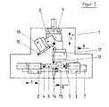
- the yielding cushion 15 is set against the roller. It is located in the radial direction opposite the grinding wheel 13. When the grinding wheel acts on the roller 6, this will bend laterally and thereby tend to transverse vibrations, especially when the length / diameter ratio is greater than shown in the drawing. Also, tubular rolls with low material thickness are particularly susceptible to such vibrations.
- the device 14 is exactly opposite the grinding wheels 12 and 13.
- the roller 6 to be ground by means of the grinding table 7 in the axial direction of the grinding wheel is moved past, also changes the position of the Device 14 in relation to the grinding wheel. It is therefore advantageous if, over the axial extension of the roller 6 to be ground, a plurality of devices with various resilient cushions are provided, as illustrated in FIG. 7, which will be explained in more detail later.
- Figures 1 and 2 illustrate at the same time a particularly preferred method according to the invention, in which the pre-grinding is carried out by means of a ceramic bonded CBN grinding wheel while the device 14 for damping the vibrations still remains out of operation.
- the grinding wheel 13 is brought into operative position for finish grinding, the device 14 is automatically coupled with it, as is shown in FIG.
- finish grinding or finishing transverse vibrations are thus effectively suppressed, so that optimum surface qualities are achieved despite a short processing time.
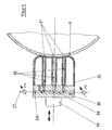
- FIG. 3 shows the view AA according to Figure 2 in an enlarged view. It explains a device for vibration damping, which is pneumatically operated.
- a base 16 is provided, which may be attached directly to the machine bed 1 or to the grinding table 7.
- the base 16 carries a pneumatic double-acting thrust cylinder 17, in which a piston 18 can be acted upon from two sides.
- the piston 18 carries a piston rod 19, to which a mounting plate 20 is located.
- On the mounting plate 20 is the yielding Pad 15 glued or vulcanized.
- the pad may be made of a rubber-like material or a plastic with closed hollow cells, which is thus particularly flexible and adaptable. It is crucial that the outer surface of the resilient pad 15, although elastic, but yet resistant and resistant to abrasion.
- the roller 21 and 22 are compressed air lines through which the thrust cylinder is controlled. He can thus press the resilient pad 15 with precisely adjustable contact force against the roller 6.
- the roller 6, which in this case is a hollow roller is acted on both sides between the grinding wheel 13 and the resilient pad 15. The roller will thus dodge slightly under the contact force of the grinding wheel 13, but occurring transverse vibrations are suppressed by the damping effect of the resilient pad 15.
- the basic position of it yielding pad 15 before the start of the grinding process is adjustable. For example, at the beginning of the contact force zero, so that only under the action of the grinding wheel 13, a depression of the roller 6 takes place in the resilient pad 15.
- a device 14 for vibration damping in which the resilient pad 23 is formed as a hollow body with an elastic outer skin, comparable to the pneumatic tire of vehicles.
- compressed air may be introduced into the interior of the resilient pad 23 with a supply conduit 24, whereby different elasticity characteristics may be achieved.
- FIG. 5 also explains a compliant pad 26 filled with a pressure medium, which is also located on a mounting plate 25 and connected thereto.
- the mounting plate 25 is connected to a supply line 27 for the pressure medium, for the compressed air comes into question in the first place.
- the pressure medium Via an internal, located in the mounting plate 25 channel 28, the pressure medium is introduced into the cavity of the resilient pad 26.
- the resilient pad 26 tubes 30 are passed, which consist of the outer skin of the pad 26 in one piece, but have no connection to the interior of the pad 26.
- the hoses 30 are connected to a channel system 29, which is located in the mounting plate 25 and by a cooling and lubricating medium by means of the hoses 30 is applied directly to the contact surface of the resilient pad 26 on the roller 6.
- the hoses 30 end in outlet openings 31, which are directed directly to the roller 6.
- the outlet openings 31 open on the surface of the roller 6, so that the coolant and lubricant reaches exactly where it is most needed.
- the pressure medium located in the hollow compliant padding can simultaneously serve as coolant and lubricant, separate supply lines for the pressure medium of the pad on the one hand and the cooling and lubricating medium on the other hand are no longer required.
- the constructive implementation which is advantageous in this case is shown in FIG. 6.
- a compliant pad 34 is glued or vulcanized onto a mounting plate 32 again, wherein a supply line 33 via a pressure regulator P21 leads into the interior of the resilient pad 34.
- the resilient pad is provided at its the roller 6 facing end side with a number of outlet openings 35.
- the pressure medium of the pad passes continuously through the outlet openings 35 in the direction of the surface of the roller 6.
- the resilient pad 34 must be continuously updated pressure medium so that the required contact pressure is maintained.
- FIGS. 4 to 6 show how well the inflatable pads conform to the contour of the roller.
- the cooling and lubricating medium between the resilient pad and the roller forms a film, comparable to the water film in the so-called aquaplaning or air cushion in vehicles of the type Hoovercraft vehicles.
- the embodiment according to FIG. 6 is particularly advantageous when working with an air cushion.
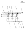
- FIG. 7 shows diagrammatically how the actuation of the devices for vibration damping is to take place when several of these devices are provided along the axial extent of the roller 6 to be ground.
- three means 36, 37, 38 are provided, each of which a resilient pad 39, 40, 41 hires to be ground roller 6.
- the hiring takes place pneumatically, to which each of the devices 36, 37, 38 may have a push cylinder according to the figure 3.
- the oscillation amplitudes in the middle of the roller 6 clamped between the tips 4 and 5 will be greater than in the region of their outer ends, which are closer to the clamping points. Therefore, it is expedient to choose the adjusting force of the device 37 higher than that of the devices 36 and 38.
- a separate pressure control valve 44, 45, 46 is provided, so that the thrust cylinder of each device can obtain the optimum for the vibration damping pneumatic pressure.
- the compressed air supply lines P and return line L are formed together for all facilities.
Landscapes
- Engineering & Computer Science (AREA)
- Mechanical Engineering (AREA)
- Grinding Of Cylindrical And Plane Surfaces (AREA)
- Constituent Portions Of Griding Lathes, Driving, Sensing And Control (AREA)
- Finish Polishing, Edge Sharpening, And Grinding By Specific Grinding Devices (AREA)
- Polishing Bodies And Polishing Tools (AREA)
Abstract
Description
Die Erfindung betrifft ein Verfahren und eine Vorrichtung gemäß dem Oberbegriff des Anspruchs 1 bzw. 17. Ein solches Verfahren und eine solche Vorrichtung ist aus DE 16 27 998 A bekannt.The invention relates to a method and a device according to the preamble of
In vielen großtechnischen und verfahrenstechnischen Prozessen werden schlanke, langgestreckte Walzen benötigt, die im Betrieb rotieren, teilweise angetrieben und vielfach von innen geheizt oder gekühlt werden müssen. Derartige Walzen können beispielsweise eine Länge von rund 1000 mm und einen Durchmesser von 85 mm aufweisen. Die Walzen sind zudem vielfach rohrförmig mit einer geringen Wandstärke bis zu hinunter zu 1 mm. An die Oberflächengüte dieser Walzen sowie an ihre Maßhaltigkeit werden hohe Anforderungen gestellt. Das Schleifen derartiger Walzen auf das Fertigmaß und die erforderliche Oberflächengüte stellt daher hohe Anforderungen an das fachmännische Können.In many large-scale and process engineering processes, slender, elongate rolls are required which rotate during operation, are partly driven and often have to be heated or cooled from the inside. Such rolls may for example have a length of about 1000 mm and a diameter of 85 mm. The rollers are also often tubular with a small wall thickness down to 1 mm. High demands are placed on the surface quality of these rolls and on their dimensional accuracy. The grinding of such rolls to the finished size and the required surface finish therefore places high demands on the expert's skill.
Eine bekannte nachteilige Erscheinung beim Außenschleifen von Walzen besteht darin, dass diese sich seitlich ausbiegen, wenn die Schleifscheibe auf ihre Umfangsfläche einwirkt. Das kann dazu führen, dass die fertige Walze von der Zylinderform abweicht. Zudem gerät die Walze dabei in selbsterregte Querschwingungen, das sogenannte regenerative Rattern. Die Folge dieses regenerativen Ratterns sind Rattermarken an der Umfangsfläche der Walze, die eine verringerte Oberflächenqualität bedeuten und die dadurch entstandene Walze für viele Anwendungszwecke unbrauchbar machen.A known disadvantageous aspect of external grinding of rollers is that they deflect laterally when the grinding wheel acts on its peripheral surface. This can lead to the finished roll deviating from the cylindrical shape. In addition, the roller gets into self-excited transverse vibrations, the so-called regenerative rattling. The result of this regenerative rattling are chatter marks on the peripheral surface of the roll, which mean a reduced surface quality and render the resulting roll useless for many applications.
Um das Ausbiegen von Walzen beim Schleifen des Außenumfangs zu verhindern, ist es bekannt, die Walze mit einem oder mehreren Setzstöcken oder Lünetten an ihrem Außenumfang zu unterstützen. Die Setzstöcke oder Lünetten bestehen aus Stahlstützen, die eine Auflage des Rohlings bewirken. Vor allem aber führt die Auflage der rotierenden Walze an den aus Stahl bestehenden Setzstöcken oder Lünetten zu Laufspuren, die ebenfalls eine verringerte Oberflächenqualität bedeuten und nicht hingenommen werden können. Bekannte betriebliche Maßnahmen zur Beseitigung des regenerativen Ratterns haben eine Verlangsamung des Schleifprozesses zur Folge.In order to prevent bowing of rolls when grinding the outer periphery, it is known to support the roll with one or more buttocks or lunettes on its outer periphery. The pegs or lunettes are made of steel columns, which cause a support of the blank. Above all, however, the circulation of the rotating roller on the setting rods or lunettes made of steel leads to running marks, which also mean a reduced surface quality and not can be accepted. Known operational measures for the removal of regenerative rattling result in a slowing down of the grinding process.
Ein aus der betrieblichen Praxis bekanntes Verfahren der eingangs genannten Art besteht darin, dass die Walze zuerst im Einstechverfahren mit einer aus Korund bestehenden Schleifscheibe vorgeschliffen wird. Hierzu wird die Walze auf ein Vorschleifmaß in der Art bearbeitet, dass mit der Schleifscheibe mehrere Male nebeneinander eingestochen wird, bis die ganze Länge der Walze auf dieses Maß vorgeschliffen ist. Anschließend wird dieselbe Schleifscheibe abgerichtet und dann fein- oder fertiggeschliffen. Das Fertigschleifen erfolgt durch Längsschleifen, wobei die rotierende Schleifscheibe und die rotierende Walze in Längsrichtung der Walze an deren Außenumfang relativ zueinander bewegt werden. Bei einer Länge der Walze von beispielsweise 1000 mm werden hierzu Schleifscheiben mit einer Breite von beispielsweise 100 mm verwendet. Der Nachteil des bekannten Verfahrens besteht einmal darin, dass die aus Korund bestehenden Schleifscheiben häufig abgerichtet werden müssen. Das kann auch während eines einzigen Fertigschleifvorganges erforderlich werden. Insgesamt ist das bekannte Schleifverfahren sehr langwierig.A well-known from practice in the method of the type mentioned is that the roller is first pre-ground in Einstechverfahren with an existing corundum grinding wheel. For this purpose, the roller is processed to a roughing in the way that the grinding wheel is pierced several times side by side until the whole length of the roller is pre-ground to this degree. Subsequently, the same grinding wheel is dressed and then fine or finish ground. The finish grinding is carried out by longitudinal grinding, wherein the rotating grinding wheel and the rotating roller are moved in the longitudinal direction of the roller at its outer periphery relative to each other. With a length of the roller of, for example, 1000 mm, grinding wheels with a width of, for example, 100 mm are used for this purpose. The disadvantage of the known method is that the grinding wheels consisting of corundum often have to be dressed. This may also be required during a single finish grinding operation. Overall, the known grinding process is very tedious.
Aus der DE 16 27 998 A1 ist ein mitlaufender Setzstock zum Abstützen von zylindrischen Werkstücken in einer Schleifmaschine bekannt, der ein hydrostatisches Halblager ausbildet. Das zu schleifende, rotierende Werkstück ruht somit auf einem Flüssigkeitsfilm, der ständig erneuert werden muss. Zu diesem Zweck wird dem hydrostatischen Halblager ununterbrochen ein Flüssigkeitsstrom zugeführt. Die Flüssigkeit kann ein Kühlmittel sein, das beim Schleifen ohnehin erforderlich ist. Mit diesem bekannten Setzstock wurde die Zielsetzung verfolgt, das Werkstück wirksam abzustützen, seine Oberfläche zu schonen und eine reibungsarme Lagerung zu erreichen, so dass der Setzstock nicht zu oft ausgewechselt werden muss. Eine Schwingungsdämpfung und das Vermeiden von Rattermarken wurden mit dem bekannten Setzstock nicht angestrebt und sind damit in stärkerem Umfang auch nicht erreichbar. Da das Halblager aus Metall besteht, muss zudem der Betrieb des hydrostatischen Halblagers stets sorgfältig überwacht werden, weil im Falle eines Zusammenbruchs des Flüssigkeitsfilms eben doch Metall auf Metall gleitet, wodurch das Werkstück beschädigt werden kann.From DE 16 27 998 A1 a follower buttstock for supporting cylindrical workpieces in a grinding machine is known, which forms a hydrostatic half bearing. The rotating workpiece to be ground thus rests on a liquid film, which must be constantly renewed. For this purpose, a liquid flow is continuously fed to the hydrostatic half bearing. The liquid can be a coolant that is required anyway during grinding. With this known set the goal was pursued to effectively support the workpiece, to protect its surface and to achieve a low-friction storage, so that the setter does not have to be replaced too often. A vibration damping and the avoidance of chatter marks were not sought with the known setter and are therefore not attainable to a greater extent. Since the half bearing is made of metal, the operation of the hydrostatic half bearing must always be carefully monitored, because in the case of Collapse of the liquid film just slides metal to metal, which can damage the workpiece.
Der Erfindung liegt daher die Aufgabe zugrunde, ein Verfahren der eingangs genannten Art zu schaffen, das die Verwendung von CBN-Schleifscheiben sowie wesentlich verringerte Bearbeitungszeiten ermöglicht und dabei dennoch zu Walzen von hoher Maßhaltigkeit und Oberflächengüte führt.The invention is therefore an object of the invention to provide a method of the type mentioned, which allows the use of CBN grinding wheels and significantly reduced processing times, while still leading to rollers of high dimensional accuracy and surface quality.
Diese Aufgabe wird durch die Merkmale des Anspruchs 1 gelöst.This object is solved by the features of claim 1.
Indem der Polsterkörper in dem der Schleifscheibe gegenüberliegenden Umfangsbereich an die zu schleifende Walze angestellt wird, werden die Querschwingungen der Walze sowie auch etwa von der Schleifscheibe herrührende Schwingungen erfolgreich gedämpft. Das regenerative Rattern tritt nicht auf, und somit sind auch die gefürchteten Rattermarken nicht mehr zu verzeichnen. Im Gegensatz zu den aus Stahl bestehenden Setzstöcken oder Lünetten führt nämlich der Polsterkörper zu keinerlei Laufspuren, die verminderte Oberflächenqualität bedeuten und für den Fachmann sofort zu erkennen sind. Die Vorschrift des der Schleifscheibe gegenüberliegenden Umfangsbereiches bedeutet, dass der Polsterkörper etwa der Schleifscheibe radial gegenüberliegend an der entgegengesetzten Seite der Walze anzubringen ist. Doch ist diese Vorschrift nicht im streng geometrischen Sinne zu verstehen, weil eine erfolgreiche Bekämpfung der Schwingungen auch dann möglich ist, wenn die Stelle, an der der Polsterkörper gegen die Walze angestellt ist, gegenüber der Schleifscheibe radial und axial in einem bestimmten Bereich variiert wird. Mit dem erfindungsgemäßen Verfahren wird eine erhebliche Verkürzung des Schleifprozesses ermöglicht, die im Vergleich zu dem bekannten Verfahren bis zu 50% betragen kann. Das Anstellen des Polsterkörpers führt beim Einstechschleifen ebenso zum Erfolg wie beim Längsschleifen.By the pad body is made in the circumferential area opposite the grinding wheel to the roller to be ground, the transverse vibrations of the roller as well as resulting from the grinding wheel vibrations are successfully damped. The regenerative rattle does not occur, and thus the dreaded chatter marks are no longer recorded. In contrast to the steel pegs or lunettes, the upholstery body does not lead to any running marks which mean reduced surface quality and can be recognized immediately by the person skilled in the art. The requirement of the circumference area opposite the grinding wheel means that the cushion body, for instance, is to be mounted radially opposite the grinding wheel on the opposite side of the roller. However, this provision is not to be understood in the strict geometric sense, because a successful fight against vibrations is also possible if the point at which the cushion body is employed against the roller, is varied radially and axially in a certain range relative to the grinding wheel. With the method according to the invention a considerable shortening of the grinding process is possible, which can be up to 50% compared to the known method. The employment of the padded body leads to plunge grinding just as successful as the longitudinal grinding.
Es wird jedoch bevorzugt, das erfindungsgemäße Verfahren als Längsschleifen durchzuführen, wobei die rotierende Schleifscheibe 13 und die rotierende Walze 6 in Längsrichtung der Walze 6 an deren Außenumfang relativ zueinander bewegt werden. Hierzu kann beispielsweise die Walze, die in Spitzen gelagert und mittels dieser oder durch einen Mitnehmer zur Drehung angetrieben ist, auf einem Schleiftisch an der rotierenden Schleifscheibe vorbeigeführt werden. Jedoch ist auch die umgekehrte Anordnung denkbar. Das kontinuierlich ablaufende Längsschleifen entspricht besser einer automatisierten Verfahrensweise als das in Absätzen erfordernde Einstechschleifen; zudem tritt dabei nicht das Problem der Schleifspuren an den Übergangsstellen auf.However, it is preferred to perform the inventive method as longitudinal grinding, wherein the rotating
Mit dem erfindungsgemäßen Verfahren werden die nachteiligen Schwingungserscheinungen derart erfolgreich unterdrückt, dass eine Bearbeitung mittels CBN-Schleifscheiben möglich wird. Eine besonders vorteilhafte Ausgestaltung des erfindungsgemäßen Verfahrens besteht daher darin, dass die Walze 6 in einer einzigen Aufspannung nacheinander mit je einer keramisch gebundenen CBN-Schleifscheibe 12, 13 vor- und fertiggeschliffen wird und die Anstellung des Polsterkörpers 6 zumindest beim Nachschleifen erfolgt.With the method according to the invention, the disadvantageous oscillation phenomena are suppressed so successfully that a machining by means of CBN grinding wheels becomes possible. A particularly advantageous embodiment of the method according to the invention is therefore that the
Die folgenden vorteilhaften Ausgestaltungen des erfindungsgemäßen Verfahrens beziehen sich darauf, wie der Polsterkörper - im Folgenden zusammenfassend als "nachgiebiges Polster" bezeichnet - an die Walze angestellt und gegebenenfalls ihr gegenüber bewegt wird.The following advantageous embodiments of the method according to the invention relate to how the cushion body - hereinafter collectively referred to as a "resilient pad" - hired to the roller and optionally moved towards her.
So hat es sich als vorteilhaft erwiesen, dass das Polster 15 elastisch nachgiebig an die Walze 6 angestellt ist. Im einfachsten Fall kann das durch eine Linearführung mit einer Anstellfeder erfolgen, deren Spannung einstellbar ist. Bevorzugt wird jedoch die Anstellung durch ein Druckmedium, aber auch eine elektronisch gesteuerte Anstellung durch Elektromotore ist denkbar.Thus, it has proved to be advantageous that the
Breite Anwendungsmöglichkeiten ergeben sich, wenn die Anstellkraft, mit der das nachgiebige Polster 15 an die Walze 6 angestellt wird, einstellbar ist und vor Beginn des Schleifvorgangs auch den Wert Null betragen kann. Die Anstellung des mindestens einen nachgiebigen Polsters erfolgt deshalb, weil die Walze sich unter dem Einfluss der Bearbeitungskräfte der Schleifscheibe in Richtung auf das Polster ausbiegt.Wide application possibilities arise when the contact force with which the
Eine betriebstechnisch besonders gut zu beherrschende Steuerung der Anstellkraft ergibt sich durch eine pneumatische Anstellung des nachgiebigen Polsters 15 an die Walze 6.A control of the adjusting force, which can be controlled particularly well from a technical point of view, results from a pneumatic adjustment of the yielding
Am einfachsten wird das erfindungsgemäße Verfahren gemäß einer weiteren Ausgestaltung dadurch durchgeführt, dass die Anstellung des mindestens einen nachgiebigen Polsters während des Schleifens an einer gleichbleibenden Stelle in der Längserstreckung der Walze erfolgt. Wenn beispielsweise die Walze zwischen Spitzen gelagert ist und die Schleifscheibe am Außenumfang der Walze in deren Längsrichtung vorbeigeführt wird, so wird man das nachgiebige Polster vorzugsweise im wesentlichen in der axialen Mitte der Walze anordnen, weil dort die stärksten Querschwingungen auftreten.The simplest method of the invention according to another embodiment is carried out in that the employment of the at least one resilient pad during grinding takes place at a constant point in the longitudinal extent of the roller. For example, if the roller is mounted between tips and the grinding wheel is guided past the outer circumference of the roller in the longitudinal direction, it is preferable to arrange the resilient pad substantially in the axial center of the roller, because there the strongest transverse vibrations occur.
Eine noch besser angepasste Schwingungsdämpfung erfolgt, indem das mindestens eine nachgiebige Polster 15 und die Walze 6 während des Schleifvorganges parallel zur Längsrichtung der Walze 6 relativ zueinander bewegt werden. Wird dabei das nachgiebige Polster 15 der Schleifscheibe 13 radial gegenüberliegend zusammen mit dieser relativ zur Walze 6 bewegt, so befindet sich das Polster stets gegenüberliegend der Schleifscheibe und somit an der Stelle der Schwingungserregung. Auf diese Weise ist eine besonders wirksame Bekämpfung der Schwingungen zu erreichen.An even better adapted vibration damping takes place by the at least one
Die im Folgenden zitierten Weiterbildungen beziehen sich auf die Ausgestaltung des Polsters und die damit zusammenhängende Zufuhr eines Schmier- und Kühlmittels in dem Bereich, in dem das nachgiebige Polster an die Walze angestellt wird.The developments cited below relate to the configuration of the pad and the associated supply of a lubricant and coolant in the region in which the resilient pad is placed against the roller.
So ist es zum Beispiel vorteilhaft, wenn sich das nachgiebige Polster 15, 23, 26, 34 beim Anstellen an die zu schleifende Walze 6 an deren zylindrische Kontur anpasst. Die Anpassung kann besonders vorteilhaft dadurch erfolgen, dass ein Druckmedium, insbesondere ein Gas, auf eine nachgiebige an der zu schleifenden Walze 6 anliegende Außenhaut des Polsters 23, 26, 34 von innen einwirkt. Auf diese Weise wird das Polster wie ein Ballon aufgeblasen, der sich weich an ein Hindernis anpasst.Thus, for example, it is advantageous if the
Wegen der dabei auftretenden Reibung zwischen der Außenhaut des Polsters und der Walze ist es vorteilhaft, wenn der Anlagestelle des nachgiebigen Polsters 23, 26, 34 an der Walze 6 ein flüssiges oder gasförmiges Schmiermittel zugeführt wird. Das damit verbundene Verfahren lässt sich besonders einfach in der Weise gestalten, dass das Schmiermittel durch das Druckmedium des Polsters 34 gebildet und der Anlagestelle durch Austrittsöffnungen 35 zugeführt wird, die sich in der der Walze 6 zugewandten Außenhaut des Polsters 34 befinden.Because of the friction occurring between the outer skin of the pad and the roller, it is advantageous if the contact point of the
Weitere Ausgestaltungen beziehen sich darauf, wie das erfindungsgemäße Schleifverfahren im Einzelnen gesteuert wird.Further embodiments relate to how the grinding method according to the invention is controlled in detail.
So kann eine bestimmte Längskontur der Walze beim Schleifen dadurch erreicht werden, dass das nachgiebige Polster quer zu der Walze derart eingestellt wird, dass die Walze sich während des Schleifvorganges ausbiegt und durch das Schleifen im Endzustand eine Längskontur der Walze mit leicht konkaver oder konvexer Krümmung zustande kommt. Die Walze nimmt hierbei während des Schleifens eine gewünschte Durchbiegung ein, ohne dass Querschwingungen auftreten. Wenn das nachgiebige Polster beim Ruhezustand der Walze einen gewissen geringen Abstand von deren Außenumfang hat, wird die Walze sich unter dem Einfluß der Schleifscheibe ausbiegen, bis sie das Polster berührt. Aber auch das Einstellen einer Vorspannung ist möglich, wobei dann die Walze in Richtung auf die Schleifscheibe vorgewölbt wird. Bei richtiger Steuerung der entsprechenden Schleifprozesse ergeben sich Walzen mit einer axialen Längskontur, die in gewünschter Weise konkav oder konvex gewölbt verläuft.Thus, a certain longitudinal contour of the roller during grinding can be achieved by setting the compliant cushion across the roller so that the roller deflects during the grinding process and by grinding in the final state a longitudinal contour of the roller with a slight concave or convex curvature comes. The roller here assumes a desired deflection during grinding, without transverse vibrations occurring. If the compliant pad has a certain distance from its outer periphery when the roller is at rest, the roller will deflect under the influence of the wheel until it touches the pad. But also the setting of a bias voltage is possible, in which case the roller is bulged in the direction of the grinding wheel. With proper control of the corresponding grinding processes arise rollers with an axial longitudinal contour, which runs in the desired manner concave or convex.
Wenn die Schleifscheibe in axialer Richtung relativ zu der zu schleifenden Walze wandert, ändern sich auch die entstehenden Querschwingungen, je nachdem, in welchem Axialbereich der Walze sich die Schleifscheibe gerade befindet. Daher ist es zur Feinabstimmung des Schleifvorganges vorteilhaft, wenn die Anstellkraft des mindestens einen nachgiebigen Polsters während des Schleifvorganges verändert wird und/oder für mehrere Polster 39, 40, 41 auf unterschiedliche Werte eingestellt wird. Die Änderung der Anstellkraft wird dabei nach Maßgabe des jeweils axialen Bereiches der Walze erfolgen, in dem die Schleifscheibe und/oder das Polster gerade auf die Walze einwirken. Die erforderlichen Werte können durch Berechnungen oder praktische Versuche schnell ermittelt werden.When the grinding wheel travels in the axial direction relative to the roll to be ground, the resulting transverse vibrations also change, depending on in which axial region of the roll the grinding wheel is currently located. Therefore, it is advantageous for fine tuning of the grinding process when the contact force of the at least one resilient pad is changed during the grinding process and / or is set to different values for a plurality of
Die Erfindung betrifft auch eine Vorrichtung zum Außenschleifen von Walzen, insbesondere zur Durchführung des erfindungsgemäßen Verfahrens nach den vorstehend zitierten Ansprüchen. Erfindungsgemäß vorgesehen gemäß Anspruch 17 ist somit eine Vorrichtung zum Außenschleifen von Walzen 6 , insbesondere zur Durchführung des Verfahrens nach den Ansprüchen 1 bis 16, mit Spann- und Antriebsgliedem zum Einspannen der Walze 6 an ihren stirnseitigen Enden und zum Drehantrieb der Walze 6, mit mindestens einer eine Schleifscheibe 13 antreibenden Schleifspindel 11, die in einer quer zu der Längsachse der Walze 6 verlaufenden Richtung verfahrbar ist, wodurch die Schleifscheibe 13 gegen die Walze 6 anstellbar ist, mit Antrieben zur gegenseitigen Längsverschiebung von Walze 6 und Schleifscheibe 13 und mit mindestens einer in dem der Schleifscheibe 13 entgegengesetzten Umfangsbereich der Walze 6 befindlichen Einrichtung 14, durch die ein Polsterkörper 15, 23, 26, 34, 39, 40, 41 aus einem elastischen Vollmaterial oder einer elastischen, mit einem elastischen Druckmedium gefüllten Außenhaut ebenfalls quer zur Längsrichtung der Walze 6 gegen deren Umfang anstellbar ist.The invention also relates to a device for external grinding of rollers, in particular for carrying out the method according to the invention according to the above-cited claims. According to the invention provided according to
Die Einrichtung zum Anstellen des Polsterkörpers (des nachgiebigen Polsters) kann zum Beispiel an dem Maschinenbett oder an einem Schleiftisch vorhanden sein, der auch die zu schleifende Walze trägt. Das Anstellen kann mechanisch, elektrisch oder durch ein Druckmedium erfolgen.The means for adjusting the cushion body (the compliant pad) may for example be provided on the machine bed or on a grinding table which also carries the roll to be ground. The hiring can be done mechanically, electrically or by a pressure medium.
Die folgenden Ausgestaltungen beziehen sich darauf, wie die Anstellkraft konstruktiv vorteilhaft und in ihrer Höhe gezielt aufgebracht werden kann. So ist es zum Steuern eines hochwertigen Schleifprozesses wesentlich, dass eine Steueranordnung zum Einstellen der Anstellkraft vorhanden ist, mit der das nachgiebige Polster 15 gegen den Umfang der zu schleifenden Walze 6 angestellt ist.The following embodiments relate to how the contact force can be constructively advantageous and selectively applied in height. Thus, it is essential for controlling a high-quality grinding process that a control arrangement for adjusting the adjusting force is provided, with which the
Sind mehrere längs der zu schleifenden Walze 6 angeordnete nachgiebige Polster 39, 40, 41 vorhanden, so ist es vorteilhaft, dass die Anstellkraft eines jeden Polsters 39, 40, 41 einzeln und unabhängig von den anderen Polstern einstellbar ist.If a plurality of
Besonders gute Steuermöglichkeiten ergeben sich, wenn die Einrichtung zum Anstellen des nachgiebigen Polsters 15 einen doppelt wirkenden pneumatischen Schubzylinder 17 umfasst, an dessen Kolbenstange 19 das Polster 15 befestigt ist. Sind dabei mehrere längs der zu schleifenden Walze 6 angeordnete nachgiebige Polster 39, 40, 41 vorhanden, so wird jedem pneumatischem Schubzylinder ein eigenes Druckregelventil 44, 45, 46 zugeordnet. Auf diese Weise ist eine perfekte pneumatische Steuerung gewährleistet, mit der die Schwingungen an mehreren Stellen der Axialerstreckung der Walze erfolgreich gedämpft werden.Particularly good control possibilities arise when the device for adjusting the
Besonderes Augenmerk ist auf die Ausgestaltung des Polsters zu richten. Die einfachste Lösung besteht darin, dass das nachgiebige Polster 15 durch einen Körper aus einem elastischen Vollmaterial gebildet ist. Ein hochwertiger, mit geschlossenen Zellen ausgebildeter Schaumkunststoff, der eine abriebfeste Oberfläche aufweist oder damit versehen ist, kann diese Aufgabe bereits gut erfüllen. Er wird sich bereits in einem gewissen Umfang an die Außenkontur der Walze anpassen und auf diese Weise die Schwingungen erfolgreich dämpfen.Particular attention should be paid to the design of the upholstery. The simplest solution is that the
Weitere Vorteile sind zu erzielen, wenn das nachgiebige Polster 23 durch einen Hohlkörper aus einer elastischen Außenhaut gebildet ist, in dem sich ein Druckmedium befindet. Dieses Druckmedium kann ein Gas, vorzugsweise Druckluft sein. Ein unter Druck stehender Hohlkörper ist zur Anpassung an die Außenkontur der Walze besonders gut geeignet, wobei die Wirkung noch dadurch gesteuert werden kann, dass der Innendruck je nach dem auszuführenden Schleifprozeß optimal eingestellt wird.Further advantages can be achieved if the
Gerade weil derartige Polster sich gut an die Außenkontur der Walze anpassen, wird auch eine erhebliche Reibung zwischen dem nachgiebigen Polster und der Walze auftreten. Um diese herabzusetzen, ist es erforderlich, dass der Anlagestelle ein Schmier- und Kühlmittel zugeführt wird. Hierzu sind gemäß einer vorteilhaften Ausgestaltung Zufuhrleitungen vorgesehen, die im Bereich der Anlagestelle des nachgiebigen Polsters an der Walze münden und durch die der Anlagestelle ein Schmiermittel zugeführt wird. Als Schmiermittel kommen dabei die in der Schleiftechnik üblichen Schleifemulsionen, synthetische Kühlschmierstoffe und Schleiföle in Betracht. Ebenso kann aber auch Druckluft in Frage kommen. Werden dabei die das Schmiermittel führenden Zufuhrleitungen durch das nachgiebige Polster hindurch unmittelbar zur Anlagestelle des Polsters an der Walze geführt, so befindet sich das Schmiermittel unmittelbar dort, wo es am stärksten wirken kann. Bei einem flüssigen Schmiermittel bildet sich zwischen der Walze und dem nachgiebigen Polster ein Film aus, der dem Aquaplaning des Autoreifens entspricht und besonders wirksam ist. Wird mit Druckluft geschmiert, so kann ein Luftkissen ausgebildet werden, wie es von Luftkissenfahrzeugen bekannt ist. Es muß hervorgehoben werden, dass der Schmiermittelfilm oder das Luftkissen die Reibungsverluste beim Schleifen wirksam herabsetzen, ohne dass dadurch die Wirkung der Schwingungsdämpfung verringert wird.Just because such pads adapt well to the outer contour of the roller, a considerable friction between the resilient pad and the roller will occur. To reduce this, it is necessary that the lubrication and cooling agent is supplied to the contact point. For this purpose, supply lines are provided according to an advantageous embodiment, which open in the region of the contact point of the resilient pad on the roller and through which the contact point, a lubricant is supplied. Suitable lubricants are the grinding emulsions, synthetic coolants and grinding oils customary in grinding technology. But also compressed air can be considered. If the supply lines leading the lubricant are guided through the resilient pad directly to the contact point of the pad on the roller, then the lubricant is located directly where it can act most strongly. In the case of a liquid lubricant, a film forms between the roller and the compliant pad, which corresponds to the hydroplaning of the automobile tire and is particularly effective. If lubricated with compressed air, so an air cushion can be formed, as it is known from hovercraft. It must be emphasized that the lubricant film or air cushion effectively reduces the friction losses during grinding without thereby reducing the effect of vibration damping.
Eine konstruktiv besonders wirksame Lösung besteht darin, dass die durch das nachgiebige Polster 26 hindurchgeführten, das Schmiermittel führenden Zufuhrleitungen als Schläuche 30 ausgebildet sind, die mit der elastischen Außenhaut des Polsters 26 aus einem Stück bestehen, wobei das Schmiermittel und das Druckmedium voneinander getrennt sind.A structurally particularly effective solution consists in that the supply lines leading through the
Kommt jedoch das Druckmedium des Polsters selbst als Kühlmittel in Frage, so ist es konstruktiv besonders einfach, dass die elastische Außenhaut des nachgiebigen Polsters 34 an ihrer der zu schleifenden Walze 6 zugewandten Anlagefläche mit einer Vielzahl von Austrittsöffnungen versehen ist, durch die hindurch das Druckmedium zur Ausbildung des kühlenden und schmierenden Films an die Anlagestelle übertritt. Bei dieser Ausbildung muß somit ständig Druckmedium aus dem nachgiebigen Polster an die Anlagestelle nach außen übertreten. Es ist eine ständige Zufuhr des Druckmediums erforderlich, die indessen durch Druckregelventile ohne weiteres zu beherrschen ist. Die Lösung kann noch weiter dadurch perfektioniert werden, dass auch die pneumatische Steuerung des Schubzylinders, an dessen Kolbenstange sich das nachgiebige Polster befindet, in den Vorgang mit einbezogen wird.However, if the pressure medium of the pad itself as a coolant in question, it is structurally particularly simple that the elastic outer skin of the
Zur Durchführung des im Verfahrensanspruch 3 erwähnten zweistufigen Schleifvorganges mit Anstellen des nachgiebigen Polsters 6 an die Walze zumindest beim Nachschleifen wird hinsichtlich der Vorrichtung konstruktiv in vorteilhafter Weise vorgesehen, dass ein Schleifspindelstock 8 mit zwei Schleifspindeln 10, 11 vorgesehen ist, die wahlweise in Wirkstellung bringbar sind und von denen die erste 10 eine keramisch gebundene CBN-Schleifscheibe 12 zum Vorschleifen und die zweite eine keramisch gebundene CBN-Schleifscheibe 13 zum Fertigschleifen trägt, wobei eine selbsttätige Koppelung vorgesehen ist, durch die die mindestens eine Einrichtung zum Anstellen des nachgiebigen Polsters 15 an die zu schleifende Walze 6 aktiviert wird, wenn die zweite Schleifspindel 11 in Wirkstellung gebracht wird. Die erfindungsgemäße Vorrichtung wird auf diese Weise für eine Automatisierung vorbereitet, die in der modernen Massenfertigung auf Fertigungsstraßen vielfach gewünscht wird.To carry out the mentioned in the process claim 3 two-stage grinding process with hiring the
Die Erfindung wird anschließend anhand von Ausführungsbeispielen, die in den Figuren dargestellt sind, noch näher erläutert. In den Figuren ist das Folgende dargestellt:
- Figur 1 zeigt eine Vorrichtung durch Durchführung des erfindungsgemäßen Verfahrens, wobei die Phase des Vorschleifens dargestellt ist.
Figur 2 stellt die Vorrichtung gemäß Figur 1 in der Phase des Fertigschleifens dar.Figur 3 ist eine vergrößerte Ansicht entsprechend der Blickrichtung A-A gemäß Figur 2 und zeigt Einzelheiten des nachgiebigen Polsters im Zusammenwirken mit der zu schleifenden Walze.Figur 4 hat eine andere Ausführung des nachgiebigen Polsters zum Gegenstand.Figur 5 zeigt die Zufuhr eines Schmiermittels im Bereich des nachgiebigen Polsters.Figur 6 veranschaulicht ein nachgiebiges Polster, dessen Druckmedium zugleich als Schmiermittel dient.Figur 7 enthält ein Schema, das die Steuerung mehrerer Einrichtungen zum Anstellen elastischer Polster an unterschiedlichen axial beabstandeten Stellen der Walze verdeutlicht.
- FIG. 1 shows a device by carrying out the method according to the invention, wherein the pre-grinding phase is shown.
- FIG. 2 shows the device according to FIG. 1 in the phase of finish grinding.
- Figure 3 is an enlarged view corresponding to the viewing direction AA of Figure 2 and showing details of the resilient pad in cooperation with the roller to be ground.
- Figure 4 has another embodiment of the resilient pad for the subject.
- Figure 5 shows the supply of a lubricant in the region of the resilient pad.
- Figure 6 illustrates a resilient pad, the pressure medium also serves as a lubricant.
- Figure 7 contains a diagram illustrating the control of a plurality of means for adjusting elastic pads at different axially spaced locations of the roller.
Figur 1 veranschaulicht in schematischer Darstellung zunächst eine übliche Rundschleifmaschine zum Außenschleifen zylindrischer Teile. In einer Ansicht von oben ist ein Maschinenbett 1 zu erkennen, auf dem sich ein Werkstückspindelstock 2 und ein Reitstock 3 befinden. Werkstückspindelstock 2 und Reitstock 3 sind gegeneinander in axialer Richtung verstellbar, so dass mittels der an ihnen befindlichen Spitzen 4 und 5 die zu schleifende Walze 6 eingespannt und zur Drehung angetrieben werden kann. Die Walze kann aber auch durch Mitnehmer angetrieben werden, die fachüblich und deshalb hier nicht gesondert dargestellt sind. Der Werkstückspindelstock 2 und der Reitstock 3 befinden sich auf einem Schleiftisch 7, der als Ganzes in der Z-Richtung verfahrbar ist.FIG. 1 is a schematic representation of a conventional cylindrical grinding machine for external grinding of cylindrical parts. In a view from above, a machine bed 1 can be seen, on which a
Auf dem Maschinenbett 1 befindet sich weiter ein Schleifspindelstock 8, der um eine senkrechte Schwenkachse 9 verstellbar ist. Der Schleifspindelstock trägt eine erste Schleifspindel 10 und ein zweite Schleifspindel 11. Von diesen trägt die erste Schleifspindel 10 eine erste Schleifscheibe 12, die zum Vorschleifen oder Schruppen dient, während die zweite Schleifspindel 11 eine zum Fertigschleifen oder Schlichten bestimmte zweite Schleifscheibe 13 trägt.On the machine bed 1 is still a
Durch Schwenken um die senkrechte Schwenkachse 9 bewegt sich der Schleifspindelstock 8 in Richtung des Pfeils B, so dass wahlweise die Schleifscheibe 12 (Figur 1) oder die zweite Schleifscheibe 13 (Figur 2) in Wirkstellung gebracht werden kann. Außerdem ist der gesamte Schleifspindelstock 8 in der X-Richtung numerisch gesteuert verfahrbar, wodurch die jeweils in Wirkstellung befindliche Schleifscheibe gesteuert zur Anlage an der zu schleifenden Walze 6 kommt.By pivoting about the
Ersichtlich beträgt die axiale Länge der zu schleifenden Walze 6 ein Vielfaches der Schleifscheibenbreite, so dass zum Schleifen beim sogenannten Längsschleifen die Schleifscheibe und die zu schleifende Walze in axialer Richtung aneinander vorbei bewegt werden müssen. Hierzu kann die auf dem Schleifschlitten befindliche Walze 6 an der Schleifscheibe vorbeibewegt werden. Es ist jedoch auch die umgekehrte Anordnung möglich, dass die zu schleifende Walze in axialer Richtung feststeht, während der Schleifspindelstock an ihr vorbeibewegt wird.As can be seen, the axial length of the
Mit 14 ist eine Einrichtung zur Schwingungsdämpfung bezeichnet, durch die ein nachgiebiges Polster 15 gesteuert an die Walze angestellt werden kann. Figur 1 zeigt die Einrichtung 14 in ihrer wirkungslosen Stellung; hierbei befindet sich das nachgiebige Polster 14 im Abstand von der Oberfläche der zu schleifenden Walze. Hingegen ist in der Darstellung gemäß Figur 2 das nachgiebige Polster 15 an die Walze angestellt. Es befindet sich in radialer Richtung gegenüberliegend der Schleifscheibe 13. Wenn die Schleifscheibe auf die Walze 6 einwirkt, wird sich diese seitlich ausbiegen und dabei zu Querschwingungen neigen, besonders wenn das Längen/Durchmesser-Verhältnis größer als in der Zeichnung dargestellt ist. Auch sind rohrförmige Walzen mit geringer Materialstärke besonders anfällig für derartige Schwingungen. Indem nun das nachgiebige Polster 15 mit mäßigem, einstellbarem Druck an die Walze angestellt wird, werden die Querschwingungen gedämpft und unterdrückt, so dass das von den Fachleuten gefürchtete "regenerative Rattern" nicht auftritt. Dadurch unterbleiben auch die eine schlechte Oberflächenqualität der geschliffenen Walze verratenden Rattermarken.With a
In der Darstellung gemäß den Figuren 1 und 2 befindet sich die Einrichtung 14 zwar genau gegenüberliegend den Schleifscheiben 12 bzw. 13. Wenn aber die zu schleifende Walze 6 mittels des Schleiftisches 7 in axialer Richtung an der Schleifscheibe vorbeibewegt wird, ändert sich auch die Stellung der Einrichtung 14 im Verhältnis zu der der Schleifscheibe. Es ist daher vorteilhaft, wenn über die axiale Erstreckung der zu schleifenden Walze 6 mehrere Einrichtungen mit verschiedenen nachgiebigen Polstern vorgesehen werden, wie das die später noch näher zu erläuternde Figur 7 veranschaulicht.Although in the illustration according to Figures 1 and 2, the
Es ist aber auch denkbar, die Einrichtung 14 am Maschinenbett anzuordnen, so dass sie stets genau gegenüber der in Wirkstellung befindlichen Schleifscheibe verbleibt. Schließlich ist auch eine Lösung denkbar, bei der zwar nur eine Einrichtung 14 vorgesehen, diese aber zusammen mit der Schleifspindel gegenüber der zu schleifenden Walze axial bewegt wird, so dass die gegenseitige Zuordnung von Schleifscheibe und Einrichtung 14 in jedem Fall erhalten bleibt.However, it is also conceivable to arrange the
Die Figuren 1 und 2 verdeutlichen zugleich ein erfindungsgemäß besonders bevorzugtes Verfahren, bei dem das Vorschleifen mittels einer keramisch gebundenen CBN-Schleifscheibe erfolgt und dabei die Einrichtung 14 zur Dämpfung der Schwingungen noch außer Betrieb bleibt. Wird jedoch die Schleifscheibe 13 zum Fertigschleifen in Wirkstellung gebracht, so wird damit automatisch gekoppelt auch die Einrichtung 14 aktiviert, wie das in Figur 2 dargestellt ist. Beim Fertigschleifen oder Schlichten sind somit Querschwingungen wirksam unterdrückt, so dass trotz kurzer Bearbeitungszeit optimale Oberflächenqualitäten erzielt werden.Figures 1 and 2 illustrate at the same time a particularly preferred method according to the invention, in which the pre-grinding is carried out by means of a ceramic bonded CBN grinding wheel while the
Die Figur 3 zeigt die Ansicht A-A gemäß Figur 2 in vergrößerter Darstellung. Sie erläutert eine Einrichtung zur Schwingungsdämpfung, die pneumatisch betätigt wird. Hierzu ist ein Sockel 16 vorgesehen, der unmittelbar am Maschinenbett 1 oder an dem Schleiftisch 7 befestigt sein kann. Der Sockel 16 trägt einen pneumatischen doppelt wirkenden Schubzylinder 17, in dem ein Kolben 18 von zwei Seiten her beaufschlagt werden kann. Der Kolben 18 trägt eine Kolbenstange 19, an der sich eine Befestigungsplatte 20 befindet. Auf die Befestigungsplatte 20 ist das nachgiebige Polster 15 aufgeklebt oder aufvulkanisiert. Das Polster kann aus einem gummiartigen Werkstoff oder einem Kunststoff mit geschlossenen hohlen Zellen bestehen, der dadurch besonders nachgiebig und anpassungsfähig ist. Entscheidend ist, dass die Außenfläche des nachgiebigen Polsters 15 zwar elastisch, aber dennoch widerstandsfähig und abriebfest ist. 21 und 22 sind Druckluftleitungen, durch die der Schubzylinder gesteuert wird. Er kann somit das nachgiebige Polster 15 mit genau einstellbarer Anstellkraft gegen die Walze 6 andrücken. Wie ersichtlich ist, wird die Walze 6, die in diesem Fall eine hohle Walze ist, zwischen der Schleifscheibe 13 und dem nachgiebigen Polster 15 beidseitig beaufschlagt. Die Walze wird somit unter der Anstellkraft der Schleifscheibe 13 geringfügig ausweichen, wobei aber auftretende Querschwingungen durch die dämpfende Wirkung des nachgiebigen Polsters 15 unterdrückt werden.3 shows the view AA according to Figure 2 in an enlarged view. It explains a device for vibration damping, which is pneumatically operated. For this purpose, a
Auch die Grundstellung es nachgiebigen Polsters 15 vor Beginn des Schleifvorganges ist einstellbar. Beispielsweise kann zu Anfang die Anstellkraft Null vorliegen, so dass erst unter der Wirkung der Schleifscheibe 13 ein Eindrücken der Walze 6 in das nachgiebige Polster 15 erfolgt.The basic position of it yielding
In Figur 4 ist eine Einrichtung 14 zur Schwingungsdämpfung dargestellt, bei der das nachgiebige Polster 23 als Hohlkörper mit einer elastischen Außenhaut ausgebildet ist, vergleichbar dem Luftreifen von Fahrzeugen. Mit einer Zufuhrleitung 24 kann zum Beispiel Druckluft in das Innere des nachgiebigen Polsters 23 eingeführt werden, wobei unterschiedliche Elastizitätseigenschaften erzielt werden können. Es ist aber auch denkbar, das nachgiebige Polster mit einer Flüssigkeit zu füllen, wenn dabei ein elastisches Zurückweichen der Flüssigkeit gewährleistet ist. Auch das Füllen mit einem Gel kommt in Betracht.In Figure 4, a
Die übrige Ausbildung der Einrichtung 14 entspricht derjenigen gemäß Figur 4, insbesondere muß auch hier das Anstellen des nachgiebigen Polsters 23 an die Walze 6 mit einer besonderen Einrichtung wie beispielsweise einem Schubzylinder erfolgen.The rest of the construction of the
Die Figur 5 erläutert gleichfalls ein mit einem Druckmedium gefülltes nachgiebiges Polster 26, das sich auch hier auf einer Befestigungsplatte 25 befindet und mit dieser verbunden ist. Die Befestigungsplatte 25 ist an eine Zufuhrleitung 27 für das Druckmedium angeschlossen, für das in erster Linie Druckluft in Frage kommt. Über einen internen, in der Befestigungsplatte 25 befindlichen Kanal 28 wird das Druckmedium in den Hohlraum des nachgiebigen Polsters 26 hineingeleitet. Durch das nachgiebige Polster 26 sind Schläuche 30 hindurchgeführt, die mit der Außenhaut des Polsters 26 aus einem Stück bestehen, aber keine Verbindung zum Innenraum des Polsters 26 haben. Die Schläuche 30 sind an ein Kanalsystem 29 angeschlossen, das sich in der Befestigungsplatte 25 befindet und durch das ein Kühl- und Schmiermedium mittels der Schläuche 30 direkt auf die Anlagefläche des nachgiebigen Polsters 26 an der Walze 6 aufgebracht wird. Hierzu enden die Schläuche 30 in Austrittsöffnungen 31, die direkt auf die Walze 6 gerichtet sind. Wie ersichtlich ist, münden die Austrittsöffnungen 31 an der Oberfläche der Walze 6, so dass das Kühl- und Schmiermittel genau dorthin gelangt, wo es am dringendsten benötigt wird.FIG. 5 also explains a
Mit P11 und P12 Druckregler bezeichnet, die zum Einstellen des jeweils optimalen Betriebsdruckes der Medien dienen.Designated with P11 and P12 pressure regulators, which are used to set the optimum operating pressure of the media.
Wenn das in den hohlen nachgiebigen Polstern befindliche Druckmedium zugleich als Kühl- und Schmiermittel dienen kann, sind getrennte Zuleitungen für das Druckmedium des Polsters einerseits und das Kühl- und Schmiermedium andererseits nicht mehr erforderlich. Die hierbei vorteilhafte konstruktive Verwirklichung zeigt die Figur 6.If the pressure medium located in the hollow compliant padding can simultaneously serve as coolant and lubricant, separate supply lines for the pressure medium of the pad on the one hand and the cooling and lubricating medium on the other hand are no longer required. The constructive implementation which is advantageous in this case is shown in FIG. 6.
Danach ist auf eine Befestigungsplatte 32 wieder ein nachgiebiges Polster 34 aufgeklebt oder aufvulkanisiert, wobei eine Zufuhrleitung 33 über einen Druckregler P21 in das Innere des nachgiebigen Polsters 34 führt. In diesem Fall ist das nachgiebige Polster an seiner der Walze 6 zugewandten Stirnseite mit einer Anzahl von Austrittsöffnungen 35 versehen. Somit tritt das Druckmedium des Polsters laufend durch die Austrittsöffnungen 35 in Richtung auf die Oberfläche der Walze 6 aus. In diesem Fall muß dem nachgiebigen Polster 34 fortlaufend Druckmedium nachgeführt werden, damit der erforderliche Anpressdruck aufrecht erhalten bleibt.Thereafter, a
Die Figuren 4 bis 6 zeigen, wie gut sich die aufblasbaren Polster an die Kontur der Walze anpassen. Im Falle der Figuren 5 und 6 wird auf besonders sichere Weise erreicht, dass das Kühl- und Schmiermedium zwischen dem nachgiebigen Polster und der Walze einen Film ausbildet, vergleichbar dem Wasserfilm beim sogenannten Aquaplaning oder einem Luftkissen bei Fahrzeugen vom Typ der Hoovercraft-Fahrzeuge. Die Ausbildung gemäß Figur 6 ist besonders dann vorteilhaft, wenn mit einem Luftkissen gearbeitet werden soll.FIGS. 4 to 6 show how well the inflatable pads conform to the contour of the roller. In the case of Figures 5 and 6 is achieved in a particularly secure manner that the cooling and lubricating medium between the resilient pad and the roller forms a film, comparable to the water film in the so-called aquaplaning or air cushion in vehicles of the type Hoovercraft vehicles. The embodiment according to FIG. 6 is particularly advantageous when working with an air cushion.
Figur 7 zeigt schematisch, wie das Ansteuern der Einrichtungen zur Schwingungsdämpfung erfolgen soll, wenn mehrere dieser Einrichtungen entlang der axialen Erstreckung der zu schleifenden Walze 6 vorgesehen sind. Im dargestellten Fall sind drei Einrichtungen 36, 37, 38 vorgesehen, von denen jede ein nachgiebiges Polster 39, 40, 41 an die zu schleifende Walze 6 anstellt. Das Anstellen erfolgt dabei pneumatisch, wozu jede der Einrichtungen 36, 37, 38 einen Schubzylinder gemäß der Figur 3 aufweisen kann. Ersichtlich werden die Schwingungsamplituden in der Mitte der zwischen den Spitzen 4 und 5 eingespannten Walze 6 größer sein als im Bereich ihrer äußeren Enden, die sich näher an den Einspannstellen befinden. Daher ist es zweckmäßig, die Anstellkraft der Einrichtung 37 höher zu wählen als diejenige der Einrichtungen 36 und 38. Entsprechend ist in der Druckluft-Zuleitung P für jede der Einrichtungen 36, 37, 38 ein eigenes Druckregelventil 44, 45, 46 vorgesehen, so dass der Schubzylinder einer jeden Einrichtung den für die Schwingungsdämpfung optimalen pneumatischen Druck erhalten kann. Im übrigen sind die Druckluftzuleitungen P und -rückleitung L für alle Einrichtungen gemeinsam ausgebildet.FIG. 7 shows diagrammatically how the actuation of the devices for vibration damping is to take place when several of these devices are provided along the axial extent of the
- 11
- Maschinenbettmachine bed
- 22
- WerkstückspindelstockWorkhead
- 33
- Reitstocktailstock
- 44
- Spitzetop
- 55
- Spitzetop
- 66
- Walzeroller
- 77
- Schleiftischgrinding table
- 88th
- SchleifspindelstockWheelhead
- 99
- Schwenkachseswivel axis
- 1010
- erste Schleifspindelfirst grinding spindle
- 1111
- zweite Schleifspindelsecond grinding spindle
- 1212
- erste Schleifscheibefirst grinding wheel
- 1313
- zweite Schleifscheibesecond grinding wheel
- 1414
- Einrichtung zur SchwingungsdämpfungDevice for vibration damping
- 1515
- nachgiebiges Polstersoft upholstery
- 1616
- Sockelbase
- 1717
- Schubzylinderpush cylinder
- 1818
- Kolbenpiston
- 1919
- Kolbenstangepiston rod
- 2020
- Befestigungsplattemounting plate
- 2121
- Druckluft-LeitungCompressed air line
- 2222
- Druckluft-LeitungCompressed air line
- 2323
- nachgiebiges Polstersoft upholstery
- 2424
- Zufuhrleitungsupply line
- 2525
- Befestigungsplattemounting plate
- 2626
- nachgiebiges Polstersoft upholstery
- 2727
- Zufuhrleitungsupply line
- 2828
- interner Kanalinternal channel
- 2929
- Kanalsystemchannel system
- 3030
- Schlauchtube
- 3131
- Austrittsöffnungenoutlet openings
- 3232
- Befestigungsplattemounting plate
- 3333
- Zufuhrleitungsupply line
- 3434
- nachgiebiges Polstersoft upholstery
- 3535
- Austrittsöffnungenoutlet openings
- 36, 37, 38,36, 37, 38,
- Einrichtung zur SchwingungsdämpfungDevice for vibration damping
- 39, 40, 4139, 40, 41
- nachgiebiges Polstersoft upholstery
- 42, 4342, 43
- Steuerleitungcontrol line
- 44,45,4644,45,46
- DruckregelventilPressure control valve
Claims (28)
- A method for peripheral grinding the exterior of a rotating roller (6) supported at its ends, by means of a rotating grinding wheel (13), with the length of said roller (6) being a multiple of the width of said grinding wheel, characterized in that during grinding, at least one padding body (15, 23, 26, 34, 39, 40, 41) made of a solid elastic material, or an elastic outer skin filled with an elastic pressure medium, is brought into contact with the roller (6) to be ground in the peripheral area opposite said grinding wheel (13).
- The method of claim 1 characterized in that it is performed as a longitudinal grinding operation, in which said rotating grinding wheel (13) and said rotating roller (6) are moved relative to each other on the outer periphery of said roller (6) in a longitudinal direction of the latter.
- The method of claim 2 characterized in that said roller (6) is successively rough-ground and finish-ground in a single clamping, each time using a ceramically bonded CBN grinding wheel (12, 13), and that said padding body (6) is brought into contact with the roller at least for regrinding.
- The method of one of the preceding claims characterized in that said padding body (15) is brought into contact with said roller (6) in an elastically flexible manner.
- The method of one of the preceding claims characterized in that the force with which said padding body (15) is brought into contact with said roller (6) is adjustable and may also be at zero before the beginning of the grinding operation.
- The method of one of the preceding claims characterized in that said padding body (15) is brought into contact with said roller (6) pneumatically.
- The method of one of the preceding claims characterized in that said at least one padding body will be brought into contact with said roller at a constant position in the longitudinal extension of said roller during grinding.
- The method of one of the preceding claims characterized in that during the grinding operation, said at least one padding body (15) and said roller (6) will be moved relative to each other and in parallel to the longitudinal direction of said roller (6).
- The method of claim 8 characterized in that in doing so, said padding body (15), in a radial position substantially opposite said grinding wheel (13), will be moved relative to said roller (6) together with said grinding wheel (13).
- The method of one of the preceding claims characterized in that when said flexible padding body (15, 23, 26, 34) is brought into contact with the roller (6) to be ground, the former will adapt to the cylindrical contour of said roller (6).
- The method of claim 10 characterized in that such an adaptation will be obtained by a pressure medium, in particular a gas, acting from the inside on an elastic outer skin of said padding body (23, 26, 34) which lies against said roller (6) to be ground.
- The method of one of the preceding claims characterized in that a liquid or gaseous lubricant will be supplied to the place where said flexible padding body (26, 34) contacts said roller (6).
- The method of claim 12 which refers back to claim 11 characterized in that said lubricant is formed by the pressure medium of said padding body (34) and will be supplied to the contact site via exit apertures (35) provided in the outer skin of said padding body (34) facing said roller (6).
- The method of one of the preceding claims characterized in that said padding body will be set transversely to said roller so as to cause said roller to bend out during grinding, and that grinding in the final state will produce a longitudinal contour of said roller which exhibits a slightly concave or convex curvature.
- The method of one of the preceding claims characterized in that the force with which said at least one padding body is brought into contact with said roller will be varied during grinding and/or will be set at a different value for each of a plurality of padding bodies (39, 40, 41).
- The method of claim 15 characterized in that the force with which the padding body is brought into contact with said roller will be varied according to the respective axial area of said roller where either said grinding wheel and/or said padding body will act on said roller.
- A device for externally grinding rollers (6), in particular for performing the method of claims 1 to 16, with clamping and driving elements for clamping said roller (6) at its frontal ends, and for rotationally driving said roller (6), including at least one grinding spindle (11) driving at least one grinding wheel (13), said spindle (11) being capable of travelling in a direction transverse to the longitudinal axis of said roller (6) so as to bring said grinding wheel (13) into contact with said roller (6), including drives for the mutual longitudinal displacement of said roller (6) and said grinding wheel (13), and including at least one means (14) located in the peripheral area of said roller (6) opposite said grinding wheel (13) characterized in that said means (14) enables a padding body (15, 23, 26, 34, 39, 40, 41) of a solid elastic material, or an elastic outer skin filled with an elastic pressure medium, to be brought into contact with the periphery of said roller (6) likewise transversely to a longitudinal direction thereof.
- The device of claim 17 characterized by control means for adjusting the force with which said padding body (15) is brought into contact with the periphery of said roller (6) to be ground.
- The device of claim 18 including several flexible padding bodies (39, 40, 41) arranged along said roller (6) to be ground characterized in that the force with which each padding body (39, 40, 41) is brought into contact with said roller can be adjusted individually and independent of the other padding bodies.
- The device of claim 18 or 19 characterized in that the means for bringing said flexible padding body (15) into contact with said roller comprises a double-action pneumatic pushing actuator (17) which has said padding body (15) mounted on its connecting rod (19).
- The device of claim 20 including several padding bodies (39, 40, 41) arranged along said roller (6) to be ground characterized in that a respective pressure control valve (44, 45, 46) is provided for each pneumatic pushing actuator.
- The device of one of claims 17 to 21 characterized in that said elastic pressure medium is pressurized air.
- The device of one of claims 17 to 22 characterized in that supply lines are provided which terminate at the roller in the area of the contact point of said padding body and through which a lubricant is supplied to said contact point.
- The device of claim 23 characterized in that grinding emulsions, synthetic cooling lubricants, grinding oils or a gas, in particular pressurized air, are intended for use as lubricants.
- The device of claims 23 or 24 characterized in that the supply lines for supplying said lubricant extend through said padding body directly to the contact point of said padding body on the roller.
- The device of claim 25 including a padding body (26) consisting of an elastic outer skin filled with an elastic pressure medium characterized in that the supply lines which extend through said padding body (26) and supply said lubricant are in the form of tubes (30) which are integrally formed with the elastic outer skin of said padding body (26), with said lubricant and said pressure medium being separated from each other.
- The device of claim 26 characterized in that the elastic outer skin of the elastic padding body (34) has a plurality of exit apertures in its contact surface facing said roller (6) to be ground, through which said pressure medium passes on to said contact point in order to form a cooling and lubricating film thereon.
- The device of one of claims 17 to 27 characterized in that a grinding spindle stock (8) including two grinding spindles (10, 11) is provided which can be selectively moved into their active positions, with the first (10) of said spindles carrying a ceramically bonded CBN grinding wheel (12) for rough grinding and the second of said spindles carrying a ceramically bonded grinding wheel (13) for finish grinding, and that an automatic coupling is provided which is used for activating said at least one means for bringing said elastic padding body (15) into contact with said roller (6) to be ground when said second grinding spindle (11) is moved into its active position.
Applications Claiming Priority (3)
| Application Number | Priority Date | Filing Date | Title |
|---|---|---|---|
| DE10232394A DE10232394B4 (en) | 2002-07-17 | 2002-07-17 | Method and device for grinding a rotating roller |
| DE10232394 | 2002-07-17 | ||
| PCT/EP2003/007788 WO2004007145A1 (en) | 2002-07-17 | 2003-07-17 | Method and device for grinding a rotating roller using an elastic steady-rest support |
Publications (2)
| Publication Number | Publication Date |
|---|---|
| EP1521663A1 EP1521663A1 (en) | 2005-04-13 |
| EP1521663B1 true EP1521663B1 (en) | 2006-10-25 |
Family
ID=30010119
Family Applications (1)
| Application Number | Title | Priority Date | Filing Date |
|---|---|---|---|
| EP03763887A Expired - Lifetime EP1521663B1 (en) | 2002-07-17 | 2003-07-17 | Method and device for grinding a rotating roller using an elastic steady-rest support |
Country Status (12)
| Country | Link |
|---|---|
| EP (1) | EP1521663B1 (en) |
| JP (1) | JP4030998B2 (en) |
| KR (1) | KR101026324B1 (en) |
| CN (1) | CN100379520C (en) |
| AT (1) | ATE343453T1 (en) |
| AU (1) | AU2003254370A1 (en) |
| BR (1) | BR0312660A (en) |
| CA (1) | CA2491800C (en) |
| DE (2) | DE10232394B4 (en) |
| ES (1) | ES2276116T3 (en) |
| RU (1) | RU2005104233A (en) |
| WO (1) | WO2004007145A1 (en) |
Families Citing this family (31)
| Publication number | Priority date | Publication date | Assignee | Title |
|---|---|---|---|---|
| DE102004012823A1 (en) * | 2004-03-16 | 2005-10-06 | Vollmer Werke Maschinenfabrik Gmbh | Device and method for clamping and positioning workpieces of different lengths between two tips |
| DE202004021661U1 (en) | 2004-10-27 | 2010-02-04 | Emag Holding Gmbh | synchronous grinding machine |
| DE102005024389B4 (en) * | 2005-05-27 | 2016-03-31 | Schaeffler Technologies AG & Co. KG | Method and device for grinding the outer circumferential surface of a shaft or roller-shaped workpiece |
| JP4718298B2 (en) * | 2005-10-24 | 2011-07-06 | 光洋機械工業株式会社 | Centerless grinding method and centerless grinding apparatus for bar workpiece |
| JP4912695B2 (en) * | 2006-02-24 | 2012-04-11 | 株式会社シギヤ精機製作所 | Shaft workpiece grinding method and workpiece steadying device |
| CN100441376C (en) * | 2006-05-10 | 2008-12-10 | 厦门大学 | Pneumatic end face planetary motion diamond grinding tool |
| CN100560295C (en) * | 2007-06-29 | 2009-11-18 | 上银科技股份有限公司 | Suppression mechanism for grinding cutting vibration |
| DE102007031512B4 (en) | 2007-07-06 | 2013-01-31 | Erwin Junker Maschinenfabrik Gmbh | Method for supporting and dynamically centering a rotating workpiece |
| DE102008010245B4 (en) | 2008-02-20 | 2011-02-10 | Emag Holding Gmbh | Method for grinding wavy workpieces |
| IT1401493B1 (en) * | 2010-07-30 | 2013-07-26 | Tenova Spa | CONTRAST DEVICE FOR ADJUSTMENTS OF PRODUCTS SUPPLIED BETWEEN CENTERS |
| IT1403602B1 (en) * | 2010-12-22 | 2013-10-31 | Tenova Spa | METHOD FOR THE POSITIONING OF OPERATIONAL CYLINDERS ON A GRINDING MACHINE AND GRINDING MACHINE THAT ACTIVATES THIS METHOD |
| CN102335865A (en) * | 2011-06-22 | 2012-02-01 | 苏州东茂纺织实业有限公司 | Grinder |
| CN102490093B (en) * | 2011-12-02 | 2014-01-08 | 郑州飞机装备有限责任公司 | Device for processing convexity of grinding roller |
| CN102877248B (en) * | 2012-09-13 | 2015-02-18 | 梁少奇 | Textile dyeing press roller with pressure assist to prevent uneven pressure on the middle side |
| JP6468709B2 (en) * | 2014-03-20 | 2019-02-13 | 株式会社小松製作所 | Work rest device |
| CN104139333B (en) * | 2014-07-11 | 2016-05-18 | 山东金宝电子股份有限公司 | The method for grinding of copper foil surface processor rubber roll glue-line and the arc board clamp of use thereof |
| CN104191359A (en) * | 2014-08-04 | 2014-12-10 | 南通五洲轴承有限公司 | Drawing, combing, roving and spinning roller combined grinding clamp |
| DE102014115183A1 (en) * | 2014-10-17 | 2015-03-05 | SOMATEC, Inh.: Klaus Mayer | Device for processing workpieces |
| CN105690227A (en) * | 2014-11-24 | 2016-06-22 | 宁波江丰电子材料股份有限公司 | Polishing device and polishing system |
| CN104493651B (en) * | 2014-12-10 | 2017-03-08 | 东莞市天合机电开发有限公司 | A new type of cylindrical grinding device |
| JP6972556B2 (en) * | 2017-01-10 | 2021-11-24 | 株式会社ジェイテクト | Grinding equipment and grinding method |
| CN108789137A (en) * | 2018-06-28 | 2018-11-13 | 盐城市锐克斯研磨科技有限公司 | A kind of auxiliary firm organization suitable for abrasive machine |
| CN109249311B (en) * | 2018-10-15 | 2020-06-05 | 东北大学 | Electric control roller vibration damper with improved inertia capacity |
| CN110450043B (en) * | 2019-08-28 | 2020-07-17 | 上海越洲机械制造有限公司 | Grinding mechanism and using method thereof |
| JP7395973B2 (en) * | 2019-11-11 | 2023-12-12 | 株式会社ジェイテクト | grinding equipment |
| KR102312031B1 (en) * | 2019-11-14 | 2021-10-14 | 한전원자력연료 주식회사 | Mandrel CNC system and method |
| CN112847083A (en) * | 2020-12-26 | 2021-05-28 | 江苏光明环境设备有限公司 | Efficient workpiece surface coating production line |
| KR102760639B1 (en) * | 2022-04-29 | 2025-02-03 | 주식회사 동일 | Forming method of thin plate pipe |
| KR102468331B1 (en) * | 2022-07-04 | 2022-11-17 | 주식회사 유림원색 | Gravure Printing Roller Polishing Method and Machine |
| KR102543012B1 (en) * | 2023-02-17 | 2023-06-13 | 김학규 | Roller polishing system |
| JP7432082B1 (en) | 2023-05-18 | 2024-02-16 | 知之 深瀬 | Grinding machine work support device |
Family Cites Families (6)
| Publication number | Priority date | Publication date | Assignee | Title |
|---|---|---|---|---|
| GB1160276A (en) * | 1965-12-28 | 1969-08-06 | Hobson Ltd H M | Improvements in or relating to Work Steadies |
| US3425168A (en) * | 1966-08-19 | 1969-02-04 | Babcock & Wilcox Co | Work follower rests |
| DE2163084A1 (en) * | 1971-12-18 | 1973-06-20 | Fortuna Werke Maschf Ag | ARRANGEMENT ON RUNNERS |
| JP3100640B2 (en) * | 1990-12-07 | 2000-10-16 | バンドー化学株式会社 | Grinding method of roll having rubber-like elasticity |
| JPH07178665A (en) * | 1993-12-21 | 1995-07-18 | Honda Motor Co Ltd | Grinder |
| DE19857359B4 (en) * | 1998-12-11 | 2005-09-15 | Erwin Junker Maschinenfabrik Gmbh | Method and device for machining workpieces with thin-walled areas having centric deviations in shape |
-
2002
- 2002-07-17 DE DE10232394A patent/DE10232394B4/en not_active Expired - Fee Related
-
2003
- 2003-07-17 WO PCT/EP2003/007788 patent/WO2004007145A1/en not_active Ceased
- 2003-07-17 CA CA2491800A patent/CA2491800C/en not_active Expired - Fee Related
- 2003-07-17 EP EP03763887A patent/EP1521663B1/en not_active Expired - Lifetime
- 2003-07-17 RU RU2005104233/02A patent/RU2005104233A/en not_active Application Discontinuation
- 2003-07-17 CN CNB038168138A patent/CN100379520C/en not_active Expired - Fee Related
- 2003-07-17 KR KR1020047021543A patent/KR101026324B1/en not_active Expired - Fee Related
- 2003-07-17 BR BR0312660-9A patent/BR0312660A/en not_active Application Discontinuation
- 2003-07-17 DE DE50305509T patent/DE50305509D1/en not_active Expired - Lifetime
- 2003-07-17 ES ES03763887T patent/ES2276116T3/en not_active Expired - Lifetime
- 2003-07-17 JP JP2004520664A patent/JP4030998B2/en not_active Expired - Fee Related
- 2003-07-17 AT AT03763887T patent/ATE343453T1/en not_active IP Right Cessation
- 2003-07-17 AU AU2003254370A patent/AU2003254370A1/en not_active Abandoned
Also Published As
| Publication number | Publication date |
|---|---|
| DE50305509D1 (en) | 2006-12-07 |
| AU2003254370A1 (en) | 2004-02-02 |
| RU2005104233A (en) | 2005-10-10 |
| BR0312660A (en) | 2005-04-26 |
| KR101026324B1 (en) | 2011-03-31 |
| ATE343453T1 (en) | 2006-11-15 |
| EP1521663A1 (en) | 2005-04-13 |
| KR20050019813A (en) | 2005-03-03 |
| DE10232394A1 (en) | 2004-02-26 |
| CA2491800A1 (en) | 2004-01-22 |
| CA2491800C (en) | 2011-02-22 |
| JP4030998B2 (en) | 2008-01-09 |
| ES2276116T3 (en) | 2007-06-16 |
| CN100379520C (en) | 2008-04-09 |
| CN1668421A (en) | 2005-09-14 |
| DE10232394B4 (en) | 2004-07-22 |
| JP2005537140A (en) | 2005-12-08 |
| WO2004007145A1 (en) | 2004-01-22 |
Similar Documents
| Publication | Publication Date | Title |
|---|---|---|
| EP1521663B1 (en) | Method and device for grinding a rotating roller using an elastic steady-rest support | |
| DE10234707B4 (en) | Method and device for grinding a rotationally symmetrical machine component | |
| DE102009024209B4 (en) | METHOD AND DEVICE FOR MULTILAYER GRINDING OF WORKPIECES | |
| DE4426452C1 (en) | Process for grinding concave flanks of cams of camshaft | |
| EP2150377B1 (en) | Vibration-free machining of piercers | |
| DE19634839A1 (en) | Fine machining with vibrating head | |
| DE102015206565A1 (en) | METHOD AND SYSTEM FOR EXTERNALLY GRINDING SHAFTS BETWEEN TIPS | |
| DE19751750B4 (en) | Method and device for producing polishable optical lenses from lens blanks | |
| EP3135433A2 (en) | Surface processing unit, machine tool and method of operating | |
| DE2718339A1 (en) | DEVICE AND METHOD FOR GRINDING WHEEL DRESSING | |
| DE4107462C2 (en) | Machine tool for machining workpieces | |
| EP0359304B1 (en) | Method and apparatus for the copy grinding of cylindrical or spherical surfaces | |
| DE2714222A1 (en) | METHOD AND DEVICE FOR FINE MACHINING OF THE STARTING BOLTS FOR ROLLER BODIES OF ROLLER BEARINGS | |
| DE102007050470A1 (en) | Lens-polishing method for producing optically active surfaces by polishing rough-ground lenses uses large-surface polishing tools and 5-axle computerized numerically controlled polishing machines with work-piece/tool spindles | |
| DE2639058C2 (en) | Device for shaping and sharpening a rotationally driven grinding wheel made of cubic boron nitride | |
| EP1330336B1 (en) | Centreless cylindrical grinding machine | |
| CH628695A5 (en) | Mobile rail-grinding machine | |
| EP4178761B1 (en) | Grinding head for the machining of workpieces | |
| EP3581325A1 (en) | Method and device for the treatment of wheel treads of wheels for railway vehicles | |
| DE4419366A1 (en) | Finishing machine | |
| DE4409060C3 (en) | Device for regrinding built-in rollers | |
| DE3437682C2 (en) | Device for dressing a double-cone grinding tool | |
| DE2458366A1 (en) | GRINDING PROCESS AND DEVICE FOR IMPLEMENTING THIS PROCESS | |
| DE3639264C2 (en) | Device for copy grinding and smoothing cylindrical and spherical surfaces | |
| DE3829648A1 (en) | Method for producing grooves in cylindrical rolls and grinding machine for carrying out the method |
Legal Events
| Date | Code | Title | Description |
|---|---|---|---|
| PUAI | Public reference made under article 153(3) epc to a published international application that has entered the european phase |
Free format text: ORIGINAL CODE: 0009012 |
|
| 17P | Request for examination filed |
Effective date: 20041130 |
|
| AK | Designated contracting states |
Kind code of ref document: A1 Designated state(s): AT BE BG CH CY CZ DE DK EE ES FI FR GB GR HU IE IT LI LU MC NL PT RO SE SI SK TR |
|
| AX | Request for extension of the european patent |
Extension state: AL LT LV MK |
|
| DAX | Request for extension of the european patent (deleted) | ||
| GRAP | Despatch of communication of intention to grant a patent |
Free format text: ORIGINAL CODE: EPIDOSNIGR1 |
|
| GRAS | Grant fee paid |
Free format text: ORIGINAL CODE: EPIDOSNIGR3 |
|
| GRAA | (expected) grant |
Free format text: ORIGINAL CODE: 0009210 |
|
| AK | Designated contracting states |
Kind code of ref document: B1 Designated state(s): AT BE BG CH CY CZ DE DK EE ES FI FR GB GR HU IE IT LI LU MC NL PT RO SE SI SK TR |
|
| PG25 | Lapsed in a contracting state [announced via postgrant information from national office to epo] |
Ref country code: SK Free format text: LAPSE BECAUSE OF FAILURE TO SUBMIT A TRANSLATION OF THE DESCRIPTION OR TO PAY THE FEE WITHIN THE PRESCRIBED TIME-LIMIT Effective date: 20061025 Ref country code: RO Free format text: LAPSE BECAUSE OF FAILURE TO SUBMIT A TRANSLATION OF THE DESCRIPTION OR TO PAY THE FEE WITHIN THE PRESCRIBED TIME-LIMIT Effective date: 20061025 Ref country code: SI Free format text: LAPSE BECAUSE OF FAILURE TO SUBMIT A TRANSLATION OF THE DESCRIPTION OR TO PAY THE FEE WITHIN THE PRESCRIBED TIME-LIMIT Effective date: 20061025 Ref country code: FI Free format text: LAPSE BECAUSE OF FAILURE TO SUBMIT A TRANSLATION OF THE DESCRIPTION OR TO PAY THE FEE WITHIN THE PRESCRIBED TIME-LIMIT Effective date: 20061025 Ref country code: NL Free format text: LAPSE BECAUSE OF FAILURE TO SUBMIT A TRANSLATION OF THE DESCRIPTION OR TO PAY THE FEE WITHIN THE PRESCRIBED TIME-LIMIT Effective date: 20061025 Ref country code: IE Free format text: LAPSE BECAUSE OF FAILURE TO SUBMIT A TRANSLATION OF THE DESCRIPTION OR TO PAY THE FEE WITHIN THE PRESCRIBED TIME-LIMIT Effective date: 20061025 |
|
| REG | Reference to a national code |
Ref country code: GB Ref legal event code: FG4D Free format text: NOT ENGLISH |
|
| REG | Reference to a national code |
Ref country code: CH Ref legal event code: EP |
|
| REG | Reference to a national code |
Ref country code: IE Ref legal event code: FG4D Free format text: LANGUAGE OF EP DOCUMENT: GERMAN |
|
| REF | Corresponds to: |
Ref document number: 50305509 Country of ref document: DE Date of ref document: 20061207 Kind code of ref document: P |
|
| PG25 | Lapsed in a contracting state [announced via postgrant information from national office to epo] |
Ref country code: SE Free format text: LAPSE BECAUSE OF FAILURE TO SUBMIT A TRANSLATION OF THE DESCRIPTION OR TO PAY THE FEE WITHIN THE PRESCRIBED TIME-LIMIT Effective date: 20070125 Ref country code: DK Free format text: LAPSE BECAUSE OF FAILURE TO SUBMIT A TRANSLATION OF THE DESCRIPTION OR TO PAY THE FEE WITHIN THE PRESCRIBED TIME-LIMIT Effective date: 20070125 Ref country code: BG Free format text: LAPSE BECAUSE OF FAILURE TO SUBMIT A TRANSLATION OF THE DESCRIPTION OR TO PAY THE FEE WITHIN THE PRESCRIBED TIME-LIMIT Effective date: 20070125 |
|
| GBT | Gb: translation of ep patent filed (gb section 77(6)(a)/1977) |
Effective date: 20070117 |
|
| PG25 | Lapsed in a contracting state [announced via postgrant information from national office to epo] |
Ref country code: PT Free format text: LAPSE BECAUSE OF FAILURE TO SUBMIT A TRANSLATION OF THE DESCRIPTION OR TO PAY THE FEE WITHIN THE PRESCRIBED TIME-LIMIT Effective date: 20070326 |
|
| NLV1 | Nl: lapsed or annulled due to failure to fulfill the requirements of art. 29p and 29m of the patents act | ||
| ET | Fr: translation filed | ||
| REG | Reference to a national code |
Ref country code: ES Ref legal event code: FG2A Ref document number: 2276116 Country of ref document: ES Kind code of ref document: T3 |
|
| REG | Reference to a national code |
Ref country code: IE Ref legal event code: FD4D |
|
| PLBE | No opposition filed within time limit |
Free format text: ORIGINAL CODE: 0009261 |
|
| STAA | Information on the status of an ep patent application or granted ep patent |
Free format text: STATUS: NO OPPOSITION FILED WITHIN TIME LIMIT |
|
| 26N | No opposition filed |
Effective date: 20070726 |
|
| BERE | Be: lapsed |
Owner name: ERWIN JUNKER MASCHINENFABRIK G.M.B.H. Effective date: 20070731 |
|
| REG | Reference to a national code |
Ref country code: CH Ref legal event code: PL |
|
| PG25 | Lapsed in a contracting state [announced via postgrant information from national office to epo] |
Ref country code: MC Free format text: LAPSE BECAUSE OF NON-PAYMENT OF DUE FEES Effective date: 20070731 Ref country code: CH Free format text: LAPSE BECAUSE OF NON-PAYMENT OF DUE FEES Effective date: 20070731 Ref country code: LI Free format text: LAPSE BECAUSE OF NON-PAYMENT OF DUE FEES Effective date: 20070731 Ref country code: GR Free format text: LAPSE BECAUSE OF FAILURE TO SUBMIT A TRANSLATION OF THE DESCRIPTION OR TO PAY THE FEE WITHIN THE PRESCRIBED TIME-LIMIT Effective date: 20070126 |
|
| PG25 | Lapsed in a contracting state [announced via postgrant information from national office to epo] |
Ref country code: BE Free format text: LAPSE BECAUSE OF NON-PAYMENT OF DUE FEES Effective date: 20070731 |
|
| PG25 | Lapsed in a contracting state [announced via postgrant information from national office to epo] |
Ref country code: AT Free format text: LAPSE BECAUSE OF NON-PAYMENT OF DUE FEES Effective date: 20070717 |
|
| PG25 | Lapsed in a contracting state [announced via postgrant information from national office to epo] |
Ref country code: EE Free format text: LAPSE BECAUSE OF FAILURE TO SUBMIT A TRANSLATION OF THE DESCRIPTION OR TO PAY THE FEE WITHIN THE PRESCRIBED TIME-LIMIT Effective date: 20061025 |
|
| PG25 | Lapsed in a contracting state [announced via postgrant information from national office to epo] |
Ref country code: LU Free format text: LAPSE BECAUSE OF NON-PAYMENT OF DUE FEES Effective date: 20070717 Ref country code: CY Free format text: LAPSE BECAUSE OF FAILURE TO SUBMIT A TRANSLATION OF THE DESCRIPTION OR TO PAY THE FEE WITHIN THE PRESCRIBED TIME-LIMIT Effective date: 20061025 |
|
| PG25 | Lapsed in a contracting state [announced via postgrant information from national office to epo] |
Ref country code: HU Free format text: LAPSE BECAUSE OF FAILURE TO SUBMIT A TRANSLATION OF THE DESCRIPTION OR TO PAY THE FEE WITHIN THE PRESCRIBED TIME-LIMIT Effective date: 20070426 Ref country code: TR Free format text: LAPSE BECAUSE OF FAILURE TO SUBMIT A TRANSLATION OF THE DESCRIPTION OR TO PAY THE FEE WITHIN THE PRESCRIBED TIME-LIMIT Effective date: 20061025 |
|
| REG | Reference to a national code |
Ref country code: FR Ref legal event code: PLFP Year of fee payment: 13 |
|
| PGFP | Annual fee paid to national office [announced via postgrant information from national office to epo] |
Ref country code: GB Payment date: 20150727 Year of fee payment: 13 Ref country code: DE Payment date: 20150730 Year of fee payment: 13 Ref country code: ES Payment date: 20150827 Year of fee payment: 13 Ref country code: CZ Payment date: 20150716 Year of fee payment: 13 |
|
| PGFP | Annual fee paid to national office [announced via postgrant information from national office to epo] |
Ref country code: FR Payment date: 20150630 Year of fee payment: 13 |
|
| PGFP | Annual fee paid to national office [announced via postgrant information from national office to epo] |
Ref country code: IT Payment date: 20150729 Year of fee payment: 13 |
|
| REG | Reference to a national code |
Ref country code: DE Ref legal event code: R119 Ref document number: 50305509 Country of ref document: DE |
|
| GBPC | Gb: european patent ceased through non-payment of renewal fee |
Effective date: 20160717 |
|
| PG25 | Lapsed in a contracting state [announced via postgrant information from national office to epo] |
Ref country code: FR Free format text: LAPSE BECAUSE OF NON-PAYMENT OF DUE FEES Effective date: 20160801 Ref country code: DE Free format text: LAPSE BECAUSE OF NON-PAYMENT OF DUE FEES Effective date: 20170201 |
|
| REG | Reference to a national code |
Ref country code: FR Ref legal event code: ST Effective date: 20170331 |
|
| PG25 | Lapsed in a contracting state [announced via postgrant information from national office to epo] |
Ref country code: CZ Free format text: LAPSE BECAUSE OF NON-PAYMENT OF DUE FEES Effective date: 20160717 Ref country code: GB Free format text: LAPSE BECAUSE OF NON-PAYMENT OF DUE FEES Effective date: 20160717 |
|
| PG25 | Lapsed in a contracting state [announced via postgrant information from national office to epo] |
Ref country code: IT Free format text: LAPSE BECAUSE OF NON-PAYMENT OF DUE FEES Effective date: 20160717 |
|
| PG25 | Lapsed in a contracting state [announced via postgrant information from national office to epo] |
Ref country code: ES Free format text: LAPSE BECAUSE OF NON-PAYMENT OF DUE FEES Effective date: 20160718 |
|
| REG | Reference to a national code |
Ref country code: ES Ref legal event code: FD2A Effective date: 20181129 |