EP1488712A1 - Sichtmittel zum Sichten eines Produktstroms innerhalb einer Verteilervorrichtung - Google Patents
Sichtmittel zum Sichten eines Produktstroms innerhalb einer Verteilervorrichtung Download PDFInfo
- Publication number
- EP1488712A1 EP1488712A1 EP04090239A EP04090239A EP1488712A1 EP 1488712 A1 EP1488712 A1 EP 1488712A1 EP 04090239 A EP04090239 A EP 04090239A EP 04090239 A EP04090239 A EP 04090239A EP 1488712 A1 EP1488712 A1 EP 1488712A1
- Authority
- EP
- European Patent Office
- Prior art keywords
- viewing
- means according
- region
- sighting
- front wall
- Prior art date
- Legal status (The legal status is an assumption and is not a legal conclusion. Google has not performed a legal analysis and makes no representation as to the accuracy of the status listed.)
- Granted
Links
- 235000019504 cigarettes Nutrition 0.000 claims abstract description 5
- 238000005192 partition Methods 0.000 claims description 18
- 241000208125 Nicotiana Species 0.000 abstract description 15
- 235000002637 Nicotiana tabacum Nutrition 0.000 abstract description 15
- 238000000034 method Methods 0.000 abstract description 2
- 238000001125 extrusion Methods 0.000 abstract 2
- 238000004519 manufacturing process Methods 0.000 abstract 1
- 230000000007 visual effect Effects 0.000 description 6
- 210000001520 comb Anatomy 0.000 description 5
- 238000009826 distribution Methods 0.000 description 5
- 230000007704 transition Effects 0.000 description 3
- 230000015572 biosynthetic process Effects 0.000 description 2
- 238000013461 design Methods 0.000 description 2
- 238000012545 processing Methods 0.000 description 2
- 238000011144 upstream manufacturing Methods 0.000 description 2
- 238000011161 development Methods 0.000 description 1
- 238000003780 insertion Methods 0.000 description 1
- 230000037431 insertion Effects 0.000 description 1
- 238000007689 inspection Methods 0.000 description 1
- 238000012544 monitoring process Methods 0.000 description 1
- 238000000926 separation method Methods 0.000 description 1
- 238000012549 training Methods 0.000 description 1
- 238000012546 transfer Methods 0.000 description 1
- 238000009827 uniform distribution Methods 0.000 description 1
Images




Classifications
-
- A—HUMAN NECESSITIES
- A24—TOBACCO; CIGARS; CIGARETTES; SIMULATED SMOKING DEVICES; SMOKERS' REQUISITES
- A24C—MACHINES FOR MAKING CIGARS OR CIGARETTES
- A24C5/00—Making cigarettes; Making tipping materials for, or attaching filters or mouthpieces to, cigars or cigarettes
- A24C5/39—Tobacco feeding devices
- A24C5/396—Tobacco feeding devices with separating means, e.g. winnowing, removing impurities
Definitions
- the invention relates to a viewing means for viewing a product stream within a distributor device for feeding a cigarette rod machine, the viewing means being a substantially vertically oriented zigzag sifter is formed and a sight line forming a visual space with at least one Has access for the product to be sighted within the line of sight.
- the product flow is within the distributor device from a reservoir by means of a conveying element, preferably a steep conveyor, fed to the viewing means.
- the screened product stream is then transported via a transport route into a storage shaft passed on.
- the viewing means is therefore within the distributor device in Transport direction of the product stream upstream of the storage bay.
- Known Viewing means of this type have a viewing space in which to be processed shares of not to be processed portions of the product stream separated by an air flow become.
- the product stream is formed from individual tobacco portions, which are in the range access to the visual aids.
- This object is achieved by the aforementioned visual means in that the Viewing space is shared. Due to the subdivision of the viewing space is a uniform Distribution of the product stream or the tobacco portions over the width of the Viewing means or the viewing area significantly simplified because the air flow within the viewing area the product flow or the tobacco portions only can stretch apart limited, so that the storage shaft are filled evenly can. On additional means for equalizing the product flow across the width can therefore be waived.
- the viewing area has several, preferably seven, separate chambers on.
- the formation of several individual and independent chambers facilitates the even distribution of the Product flow across the width of the viewing space, so that the filling of the downstream Stumbleachtes inevitably also takes place evenly.
- each chamber has in the region of a front side of the viewing means via a private access. This is the uniform filling of the viewing area ensured so that the chambers are filled evenly.
- the Chambers formed by partitions that extend from opposite sides of the Viewing means namely extend from the front wall to the rear wall and especially are advantageously at least partially broken.
- This type of training Ensures the most reliable and at the same time material-saving way Separation of the product flow into several partial flows within the visual space. Also allows the open design of the partitions an intervention in the viewing area of outside with little effort, in all chambers.
- the viewing space is formed visible from the outside, whereby the permanent Monitoring of the viewing process is ensured on-line.
- Sighting devices are used within distribution devices for viewing a Product stream, especially for separating from processed and not too processing shares of the product stream.
- FIG 1 is a distribution device 10 with their for the understanding of Invention helpful, essential components shown. These include in Transport direction of the product stream starting from a reservoir 11 a conveyor, which is preferably designed as a steep conveyor 12, a sight 13, a to the Viewing means 13 subsequent transport path 14 and a stowage 15th
- the Visible means 13 preferably has an access 16 for inputting the from Steep conveyor 12 supplied tobacco portions that the product stream to be viewed make up.
- the access 16 is optionally a separating roller 17th arranged, the transition of the tobacco portions of the steep conveyor 12 in the Visible 13 supported.
- the viewing means 13 comprises a viewing space 18.
- the viewing space 18 is made of a Front wall 19, a rear wall 20 and side walls 21, 22 are formed.
- a sight line 23 defined along which the product flow means an air flow is sighted.
- the front wall 19 and the rear wall 20 are spaced and expediently arranged substantially parallel to each other and formed zig-zag-shaped to form a so-called zig-zag sifter.
- the zig-zag sifter is oriented substantially vertically.
- the access 16 in the Viewing space 18 is preferably in the upper half of the viewing space 18 at the Front wall 19 arranged.
- the viewing space 18 is in at least two, preferably a plurality of sections 24 divided. Each section 24 extends substantially vertically in the direction of Line of sight 23. In an embodiment shown in Figure 2, the sections are 24 completely shielded from each other by the viewing space 18 in preferably seven separate chambers 25 is divided, which within the view means 13 no Have access to each other. Within each chamber 25, the sight line 23, or a part thereof such that seven individual lines of sight 23 are parallel but separated from each other in the viewing space 18 extend.
- the chambers 25 are through Partitions 26 are formed, which extend from the front wall 19 to the rear wall 20. Preferably, each chamber 25 is associated with an access 16.
- the partitions 26 are as well as the side walls 21, 22 formed at least partially transparent, so that an inspection of the entire viewing space 18 is ensured from the outside.
- the partitions 26 extend on the input side, ie in the region of or each Access 16, at which the transfer of the tobacco portions to the sight 13 takes place until to the steep conveyor 12 and derzelungswalze 17. The from the steep conveyor 12th supplied tobacco portions are thus inevitably in one of the chambers 25 feasible.
- the partitions 26 On the output side, ie in the region of the transition between the sight 13 and the Transport path 14, the partitions 26 extend into the transport path 14th into it.
- the partitions 26 may extend within the transport path 14, such that the sighted Product stream, in particular so that suitable for processing fractions of Product stream, from several channels within the transport path 14 evenly distributed over the width can be routed to the stowage 15.
- FIG. 25 Another particularly preferred embodiment is substantially identical so that a detailed description is omitted.
- the same reference numerals are used.
- the Chambers 25 are at least partially open, so that adjacent chambers 25 each in connection with each other.
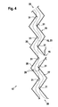
- one each extend Partition 26 forming guide elements 27 and 28 of the front wall 19 and Rear wall 20 toward each other, wherein the baffles 27 and 28 of each partition 26th lie within a plane and are spaced from each other, so that between the end faces of the opposite guide elements 27, 28 of an open Partition 26 is a distance of preferably about 30mm.
- the baffles 27, 28 extend to Forming the chambers 25 in a substantially vertical direction from a lower Floor area 29 continuously up to an upper exit area 30 of the Product stream from the viewing space 18.
- the baffles 27, 28th also with a radius around all corner regions 31 of the zigzag-shaped Front wall 19 and rear wall 20 pulled around.
- the baffles 27, 28 ramp-like, such that the area each access 16 or the transition into the viewing area 18 is free of sales.
- the baffles 27, 28 in the embodiment of Figure 5 are at least in some of the corner regions 31 at least partially interrupted. This means that the Baffles 27, 28 in front of or behind the corresponding corner regions 31 end, in such a way the affected corner regions 31 are free of baffles 27, 28.
- the selection of Corner areas 31, which are free of baffles 27, 28, is variable and depends as well the dimension and design of the baffles 27, 28 crucial from the Deflecting properties of the product stream to be viewed. Also have the Flow velocities of the air within the line of sight 23 and the angle the zig-zag-shaped front wall 19 and rear wall 20 influence the baffles 27, 28.
- the width of each chamber 25 is usually between 140 and 160mm, but preferably 147mm.
- the number of chambers 25 is variable. Every chamber 25 is freely accessible from the outside.
- the side walls 21, 22 releasably secured, namely flange plates (not shown) which extend at an angle from the front wall 19 and rear wall 20 extend.
- FIG. 7 shows a further detail of the distributor device 10.
- the Steep conveyor 12 shown in Figure 7 consists essentially of the actual Conveyor belt 35 and a frame member 36 which supports the conveyor belt 35.
- the Conveyor belt 35 has over the entire width driving means 37, which in the embodiment shown are formed as so-called combs 38.
- combs 38 are over the entire width of the conveyor belt 35th distributed side by side, so that tobacco or the like evenly over the entire Width of the conveyor belt 35 can be safely fed to the sight 13.
- the Number of combs 38 suitably corresponds to the number of to be filled Sections 24 and chambers 25 in the transport direction of the conveyor belt 35 are the Combs 38 offset from each other.
Landscapes
- Manufacturing Of Cigar And Cigarette Tobacco (AREA)
- Combined Means For Separation Of Solids (AREA)
- Vaporization, Distillation, Condensation, Sublimation, And Cold Traps (AREA)
Abstract
Description
- Fig. 1
- eine Seitenansicht einer Verteilervorrichtung im Schnitt,
- Fig. 2
- eine Vorderansicht eines Bestandteils der Verteilervonichtung gemäß Figur 1, nämlich ein Sichtmittel mit geschlossenen Trennwänden,
- Fig. 3
- eine Draufsicht auf das Sichtmittel gemäß Figur 2 im Schnitt III-III, allerdings mit offenen Trennwänden,
- Fig. 4
- eine Seitenansicht des Sichtmittels gemäß Figur 3 im Schnitt,
- Fig. 5
- eine Seitenansicht eines weiteren Sichtmittels im Schnitt,
- Fig. 6
- eine perspektivische Ansicht eines geöffneten Sichtmittels gemäß Figur 4, nämlich die Innenansicht der Vorderwand, und
- Fig. 7
- eine perspektivische Ansicht eines weiteren Bestandteils der Verteilervorrichtung gemäß Figur 1, nämlich ein Steilförderer.
Claims (13)
- Sichtmittel zum Sichten eines Produktstroms innerhalb einer Verteilervorrichtung (10) zum Beschicken einer Zigarettenstrangmaschine, wobei das Sichtmittel (13) als im wesentlichen vertikal ausgerichteter Zick-Zack-Sichter ausgebildet ist und einen eine Sichtstrecke (23) bildenden Sichtraum (18) mit mindestens einem Zugang (16) für den innerhalb der Sichtstrecke (23) zu sichtenden Produktstrom aufweist, dadurch gekennzeichnet, daß der Sichtraum (18) geteilt ist.
- Sichtmittel nach Anspruch 1, dadurch gekennzeichnet, daß der Sichtraum (18) mehrere, vorzugsweise sieben, voneinander getrennte Kammern (25) aufweist.
- Sichtmittel nach Anspruch 2, dadurch gekennzeichnet, daß sich jede Kammer (25) von einem unteren Bodenbereich (29) in im wesentlichen vertikaler Richtung zu einem oberen Austrittsbereich (30) des Produktstroms aus dem Sichtraum (18) erstreckt.
- Sichtmittel nach Anspruch 2 oder 3, dadurch gekennzeichnet, daß jede Kammer (25) im Bereich einer Vorderwand (19) des Sichtmittels (13) über einen eigenen Zugang (16) verfügt.
- Sichtmittel nach einem der Ansprüche 2 bis 4, dadurch gekennzeichnet, daß die Kammern (25) durch Trennwände (26) gebildet sind, die sich von gegenüberliegenden Seiten des Sichtmittels (13), nämlich von der Vorderwand (19) bis zur Rückwand (20) erstrecken.
- Sichtmittel nach Anspruch 5, dadurch gekennzeichnet, daß sich die Trennwände (26) im Austrittsbereich (30) bis in den Bereich einer dem Sichtmittel (13) in Transportrichtung des Produktstroms nachgeordneten Transportstrecke (14) erstrecken.
- Sichtmittel nach Anspruch 5 oder 6, dadurch gekennzeichnet, daß sich die Trennwände (26) im Bereich jedes Zugangs (16) bis in den Bereich eines Förderers (12) bzw. einer Vereinzelungswalze (17) erstrecken.
- Sichtmittel nach einem der Ansprüche 5 bis 7, dadurch gekennzeichnet, daß jede Trennwand (26) mindestens teilweise durchbrochen ist.
- Sichtmittel nach Anspruch 8, dadurch gekennzeichnet, daß sich von Vorderwand (19) und Rückwand (20) des Sichtmittels (13) jeweils eine offene Trennwand (26) bildende Leitbleche (27, 28) erstrecken, wobei die Leitbleche (27, 28) jeder offenen Trennwand (26) jeweils in derselben Ebene liegen und beabstandet voneinander angeordnet sind.
- Sichtmittel nach Anspruch 9, dadurch gekennzeichnet, daß sich die Leitbleche (27, 28) an der Vorderwand (19) und an der Rückwand (20) vom Bodenbereich (29) durchgängig bis zum Austrittsbereich (30) erstrecken.
- Sichtmittel nach Anspruch 10, dadurch gekennzeichnet, daß die Leitbleche (27, 28) an der Vorderwand (19) und an der Rückwand (20) vom Bodenbereich (29) bis zum Austrittsbereich (30) im Bereich von Eckpunkten (31) der Vorderwand (19) bzw. Rückwand (20) mindestens teilweise unterbrochen sind.
- Sichtmittel nach einem der Ansprüche 1 bis 11, dadurch gekennzeichnet, daß der Sichtraum (18) von außen einsehbar ausgebildet ist.
- Sichtmittel nach Anspruch 12, dadurch gekennzeichnet, daß mindestens die Seitenwände (21, 22) mindestens teilweise transparent ausgebildet sind.
Priority Applications (2)
| Application Number | Priority Date | Filing Date | Title |
|---|---|---|---|
| PL04090239T PL1488712T3 (pl) | 2003-06-19 | 2004-06-18 | Środek do sortowania powietrznego strumienia produktu wewnątrz urządzenia rozdzielającego |
| EP04090239A EP1488712B1 (de) | 2003-06-19 | 2004-06-18 | Sichtmittel zum Sichten eines Produktstroms innerhalb einer Verteilervorrichtung |
Applications Claiming Priority (3)
| Application Number | Priority Date | Filing Date | Title |
|---|---|---|---|
| EP03090184 | 2003-06-19 | ||
| EP03090184 | 2003-06-19 | ||
| EP04090239A EP1488712B1 (de) | 2003-06-19 | 2004-06-18 | Sichtmittel zum Sichten eines Produktstroms innerhalb einer Verteilervorrichtung |
Publications (2)
| Publication Number | Publication Date |
|---|---|
| EP1488712A1 true EP1488712A1 (de) | 2004-12-22 |
| EP1488712B1 EP1488712B1 (de) | 2011-02-02 |
Family
ID=34089681
Family Applications (1)
| Application Number | Title | Priority Date | Filing Date |
|---|---|---|---|
| EP04090239A Expired - Lifetime EP1488712B1 (de) | 2003-06-19 | 2004-06-18 | Sichtmittel zum Sichten eines Produktstroms innerhalb einer Verteilervorrichtung |
Country Status (7)
| Country | Link |
|---|---|
| US (1) | US20050029166A1 (de) |
| EP (1) | EP1488712B1 (de) |
| JP (1) | JP2005006654A (de) |
| CN (1) | CN1590249B (de) |
| AT (1) | ATE497353T1 (de) |
| DE (1) | DE502004012159D1 (de) |
| PL (1) | PL1488712T3 (de) |
Cited By (2)
| Publication number | Priority date | Publication date | Assignee | Title |
|---|---|---|---|---|
| DE102010007593A1 (de) | 2010-02-04 | 2011-08-04 | Hauni Maschinenbau AG, 21033 | Sichtmittel zum Sichten eines Produktstroms innerhalb einer Verteilervorrichtung |
| EP2625973A3 (de) * | 2012-02-08 | 2017-03-15 | Hauni Maschinenbau GmbH | Verteilervorrichtung und Verfahren zum Beschicken einer Strangmaschine der Tabak verarbeitenden Industrie |
Families Citing this family (2)
| Publication number | Priority date | Publication date | Assignee | Title |
|---|---|---|---|---|
| JP5405729B2 (ja) * | 2007-03-12 | 2014-02-05 | パナソニック株式会社 | 便座装置 |
| PL232821B1 (pl) * | 2013-11-26 | 2019-07-31 | Czech Adam Przed Obrotu Surowcami Wtornymi Hermex | Urządzenie do czyszczenia i klasyfikacji ziarnowej drobnych odpadów metalurgicznych oraz sposób czyszczenia i klasyfikacji ziarnowej drobnych odpadów metalurgicznych |
Citations (2)
| Publication number | Priority date | Publication date | Assignee | Title |
|---|---|---|---|---|
| US5645086A (en) * | 1995-03-08 | 1997-07-08 | Hauni Maschinenbau Ag | Apparatus for evacuating surplus air for the distributor of a tobacco processing machine |
| US20030034040A1 (en) * | 2001-08-16 | 2003-02-20 | Ralf Barkmann | Apparatus for building tobacco rods in cigarette making machines |
Family Cites Families (6)
| Publication number | Priority date | Publication date | Assignee | Title |
|---|---|---|---|---|
| US34040A (en) * | 1861-12-24 | Improved fuse-hood for shells | ||
| US17407A (en) * | 1857-05-26 | Improved projectile for killing whales | ||
| US4681124A (en) * | 1985-05-02 | 1987-07-21 | Hauni-Werke Korber & Co. Kg | Apparatus for manipulating particles of tobacco or filter material |
| DE3808116A1 (de) * | 1988-03-11 | 1989-09-21 | Bayer Ag | Zick-zack-sichter |
| DE19819441A1 (de) * | 1998-04-30 | 1999-11-04 | Hauni Maschinenbau Ag | Vorrichtung zum Beschicken einer Zigarettenstrangmaschine mit Tabak |
| DE10035692A1 (de) * | 2000-07-20 | 2002-01-31 | Hauni Maschinenbau Ag | Verfahren und Vorrichtung zum Vereinzeln von Tabakfasern |
-
2004
- 2004-06-18 US US10/869,834 patent/US20050029166A1/en not_active Abandoned
- 2004-06-18 PL PL04090239T patent/PL1488712T3/pl unknown
- 2004-06-18 JP JP2004180787A patent/JP2005006654A/ja not_active Withdrawn
- 2004-06-18 AT AT04090239T patent/ATE497353T1/de active
- 2004-06-18 CN CN2004100550421A patent/CN1590249B/zh not_active Expired - Fee Related
- 2004-06-18 EP EP04090239A patent/EP1488712B1/de not_active Expired - Lifetime
- 2004-06-18 DE DE502004012159T patent/DE502004012159D1/de not_active Expired - Lifetime
Patent Citations (3)
| Publication number | Priority date | Publication date | Assignee | Title |
|---|---|---|---|---|
| US5645086A (en) * | 1995-03-08 | 1997-07-08 | Hauni Maschinenbau Ag | Apparatus for evacuating surplus air for the distributor of a tobacco processing machine |
| US20030034040A1 (en) * | 2001-08-16 | 2003-02-20 | Ralf Barkmann | Apparatus for building tobacco rods in cigarette making machines |
| DE10154807A1 (de) * | 2001-08-16 | 2003-05-22 | Hauni Maschinenbau Ag | Anordnung zum Aufbau wenigstens eines Tabakstranges in einer Zigarettenstrangmaschine |
Cited By (4)
| Publication number | Priority date | Publication date | Assignee | Title |
|---|---|---|---|---|
| DE102010007593A1 (de) | 2010-02-04 | 2011-08-04 | Hauni Maschinenbau AG, 21033 | Sichtmittel zum Sichten eines Produktstroms innerhalb einer Verteilervorrichtung |
| EP2353410A2 (de) | 2010-02-04 | 2011-08-10 | HAUNI Maschinenbau AG | Sichtmittel zum Sichten eines Produktstroms innerhalb einer Verteilervorrichtung |
| EP2353410A3 (de) * | 2010-02-04 | 2015-09-30 | HAUNI Maschinenbau AG | Sichtmittel zum Sichten eines Produktstroms innerhalb einer Verteilervorrichtung |
| EP2625973A3 (de) * | 2012-02-08 | 2017-03-15 | Hauni Maschinenbau GmbH | Verteilervorrichtung und Verfahren zum Beschicken einer Strangmaschine der Tabak verarbeitenden Industrie |
Also Published As
| Publication number | Publication date |
|---|---|
| JP2005006654A (ja) | 2005-01-13 |
| US20050029166A1 (en) | 2005-02-10 |
| ATE497353T1 (de) | 2011-02-15 |
| EP1488712B1 (de) | 2011-02-02 |
| PL1488712T3 (pl) | 2011-07-29 |
| CN1590249B (zh) | 2010-09-29 |
| DE502004012159D1 (de) | 2011-03-17 |
| CN1590249A (zh) | 2005-03-09 |
Similar Documents
| Publication | Publication Date | Title |
|---|---|---|
| DE1953086C3 (de) | Stoffauflauf für eine Papiermaschine | |
| DE3042316C2 (de) | ||
| EP1364588A1 (de) | Anordnung und Verfahren zum Aufbau von wenigstens zwei Tabaksträngen in einer Zigarettenstrangmaschine | |
| DE4407305A1 (de) | Trichter für langgestreckte Teile, insbesondere Rauchwaren | |
| DE2544888A1 (de) | Zufuehrvorrichtung | |
| DE2200997B2 (de) | Vorrichtung zum Sortieren von Reiskörnern | |
| DE68911533T2 (de) | Windsichter für produktteilchen. | |
| EP1488712B1 (de) | Sichtmittel zum Sichten eines Produktstroms innerhalb einer Verteilervorrichtung | |
| DE2532528C3 (de) | Verfahren zur Einstellung eines bestimmten Verteilungsgesetzes des Durchflusses in einem Mediumsstrom, Vorrichtung zur Durchführung des Verfahrens und Verwendung des Verfahrens bzw. der Vorrichtung | |
| DE3615494C2 (de) | ||
| DE2810359A1 (de) | Vorrichtung zum selektiven sortieren von materialschnitzeln | |
| DE2130560C3 (de) | Magnetischer Starkfeld-Mehrzonen-Abscheider zum Naßaufbereiten schwach magnetischer Materialien | |
| DE102012109906A1 (de) | Verteilervorrichtung und Verfahren zum Beschicken einer Strangmaschine der Tabak verarbeitenden Industrie mit einem aus Fasermaterial bestehenden Produktstrom | |
| DE3940357A1 (de) | Maschine zur gleichzeitigen herstellung von zwei kontinuierlichen zigarettenstraengen | |
| EP1825767A1 (de) | Strömungskörper einer Zigarettenstrangmaschine | |
| DE60201314T2 (de) | Vorrichtung zum Zuführen von teilchenförmigem Gut für Anlagen zur Herstellung von gefüllten Keksen | |
| DE3704910C1 (en) | Blowing device for blowing a treatment medium onto a material web moving in the longitudinal direction | |
| DE60217318T2 (de) | Münzsortierervorrichtung und verwendung einer solchen vorrichtung | |
| DE615548C (de) | Schuettverteilungsapparat fuer die Zufuehrung von Aufgabegut zu Muellereimaschinen | |
| DE4442538A1 (de) | Doppel-Strang-Zigaretten-Herstellungs-Vorrichtung | |
| DE2624774C3 (de) | Wägegutzuführeinrichtung für eine automatische Wägeeinrichtung | |
| DE691834C (de) | Plansichter | |
| DE656408C (de) | Schleppfoerderer mit einem Siebboden | |
| DE815112C (de) | Riffelprobenteiler-Anordnung | |
| DE4332640C2 (de) | Apparat zur kontinuierlichen Verdampfungskristallisation |
Legal Events
| Date | Code | Title | Description |
|---|---|---|---|
| PUAI | Public reference made under article 153(3) epc to a published international application that has entered the european phase |
Free format text: ORIGINAL CODE: 0009012 |
|
| AK | Designated contracting states |
Kind code of ref document: A1 Designated state(s): AT BE BG CH CY CZ DE DK EE ES FI FR GB GR HU IE IT LI LU MC NL PL PT RO SE SI SK TR |
|
| AX | Request for extension of the european patent |
Extension state: AL HR LT LV MK |
|
| 17P | Request for examination filed |
Effective date: 20050610 |
|
| AKX | Designation fees paid |
Designated state(s): AT BE BG CH CY CZ DE DK EE ES FI FR GB GR HU IE IT LI LU MC NL PL PT RO SE SI SK TR |
|
| RIN1 | Information on inventor provided before grant (corrected) |
Inventor name: STUEBER, REINHARD Inventor name: HANSCH, MANUEL Inventor name: LINDEMANN, ROLF Inventor name: JUERGENS, BERNHARD Inventor name: SCHUMACHER, PETER |
|
| 17Q | First examination report despatched |
Effective date: 20070504 |
|
| GRAP | Despatch of communication of intention to grant a patent |
Free format text: ORIGINAL CODE: EPIDOSNIGR1 |
|
| GRAS | Grant fee paid |
Free format text: ORIGINAL CODE: EPIDOSNIGR3 |
|
| GRAA | (expected) grant |
Free format text: ORIGINAL CODE: 0009210 |
|
| AK | Designated contracting states |
Kind code of ref document: B1 Designated state(s): AT BE BG CH CY CZ DE DK EE ES FI FR GB GR HU IE IT LI LU MC NL PL PT RO SE SI SK TR |
|
| REG | Reference to a national code |
Ref country code: GB Ref legal event code: FG4D Free format text: NOT ENGLISH |
|
| REG | Reference to a national code |
Ref country code: CH Ref legal event code: EP |
|
| REG | Reference to a national code |
Ref country code: IE Ref legal event code: FG4D Free format text: LANGUAGE OF EP DOCUMENT: GERMAN |
|
| REF | Corresponds to: |
Ref document number: 502004012159 Country of ref document: DE Date of ref document: 20110317 Kind code of ref document: P |
|
| REG | Reference to a national code |
Ref country code: DE Ref legal event code: R096 Ref document number: 502004012159 Country of ref document: DE Effective date: 20110317 |
|
| REG | Reference to a national code |
Ref country code: NL Ref legal event code: T3 |
|
| PG25 | Lapsed in a contracting state [announced via postgrant information from national office to epo] |
Ref country code: ES Free format text: LAPSE BECAUSE OF FAILURE TO SUBMIT A TRANSLATION OF THE DESCRIPTION OR TO PAY THE FEE WITHIN THE PRESCRIBED TIME-LIMIT Effective date: 20110513 Ref country code: GR Free format text: LAPSE BECAUSE OF FAILURE TO SUBMIT A TRANSLATION OF THE DESCRIPTION OR TO PAY THE FEE WITHIN THE PRESCRIBED TIME-LIMIT Effective date: 20110503 Ref country code: PT Free format text: LAPSE BECAUSE OF FAILURE TO SUBMIT A TRANSLATION OF THE DESCRIPTION OR TO PAY THE FEE WITHIN THE PRESCRIBED TIME-LIMIT Effective date: 20110602 Ref country code: SE Free format text: LAPSE BECAUSE OF FAILURE TO SUBMIT A TRANSLATION OF THE DESCRIPTION OR TO PAY THE FEE WITHIN THE PRESCRIBED TIME-LIMIT Effective date: 20110202 |
|
| REG | Reference to a national code |
Ref country code: PL Ref legal event code: T3 |
|
| PG25 | Lapsed in a contracting state [announced via postgrant information from national office to epo] |
Ref country code: BG Free format text: LAPSE BECAUSE OF FAILURE TO SUBMIT A TRANSLATION OF THE DESCRIPTION OR TO PAY THE FEE WITHIN THE PRESCRIBED TIME-LIMIT Effective date: 20110502 Ref country code: SI Free format text: LAPSE BECAUSE OF FAILURE TO SUBMIT A TRANSLATION OF THE DESCRIPTION OR TO PAY THE FEE WITHIN THE PRESCRIBED TIME-LIMIT Effective date: 20110202 Ref country code: FI Free format text: LAPSE BECAUSE OF FAILURE TO SUBMIT A TRANSLATION OF THE DESCRIPTION OR TO PAY THE FEE WITHIN THE PRESCRIBED TIME-LIMIT Effective date: 20110202 Ref country code: CY Free format text: LAPSE BECAUSE OF FAILURE TO SUBMIT A TRANSLATION OF THE DESCRIPTION OR TO PAY THE FEE WITHIN THE PRESCRIBED TIME-LIMIT Effective date: 20110202 |
|
| REG | Reference to a national code |
Ref country code: IE Ref legal event code: FD4D |
|
| PG25 | Lapsed in a contracting state [announced via postgrant information from national office to epo] |
Ref country code: EE Free format text: LAPSE BECAUSE OF FAILURE TO SUBMIT A TRANSLATION OF THE DESCRIPTION OR TO PAY THE FEE WITHIN THE PRESCRIBED TIME-LIMIT Effective date: 20110202 Ref country code: DK Free format text: LAPSE BECAUSE OF FAILURE TO SUBMIT A TRANSLATION OF THE DESCRIPTION OR TO PAY THE FEE WITHIN THE PRESCRIBED TIME-LIMIT Effective date: 20110202 Ref country code: IE Free format text: LAPSE BECAUSE OF FAILURE TO SUBMIT A TRANSLATION OF THE DESCRIPTION OR TO PAY THE FEE WITHIN THE PRESCRIBED TIME-LIMIT Effective date: 20110202 |
|
| PG25 | Lapsed in a contracting state [announced via postgrant information from national office to epo] |
Ref country code: RO Free format text: LAPSE BECAUSE OF FAILURE TO SUBMIT A TRANSLATION OF THE DESCRIPTION OR TO PAY THE FEE WITHIN THE PRESCRIBED TIME-LIMIT Effective date: 20110202 Ref country code: CZ Free format text: LAPSE BECAUSE OF FAILURE TO SUBMIT A TRANSLATION OF THE DESCRIPTION OR TO PAY THE FEE WITHIN THE PRESCRIBED TIME-LIMIT Effective date: 20110202 Ref country code: SK Free format text: LAPSE BECAUSE OF FAILURE TO SUBMIT A TRANSLATION OF THE DESCRIPTION OR TO PAY THE FEE WITHIN THE PRESCRIBED TIME-LIMIT Effective date: 20110202 |
|
| PLBE | No opposition filed within time limit |
Free format text: ORIGINAL CODE: 0009261 |
|
| STAA | Information on the status of an ep patent application or granted ep patent |
Free format text: STATUS: NO OPPOSITION FILED WITHIN TIME LIMIT |
|
| BERE | Be: lapsed |
Owner name: HAUNI MASCHINENBAU A.G. Effective date: 20110630 |
|
| 26N | No opposition filed |
Effective date: 20111103 |
|
| REG | Reference to a national code |
Ref country code: CH Ref legal event code: PL |
|
| REG | Reference to a national code |
Ref country code: DE Ref legal event code: R097 Ref document number: 502004012159 Country of ref document: DE Effective date: 20111103 |
|
| REG | Reference to a national code |
Ref country code: FR Ref legal event code: ST Effective date: 20120229 |
|
| PG25 | Lapsed in a contracting state [announced via postgrant information from national office to epo] |
Ref country code: BE Free format text: LAPSE BECAUSE OF NON-PAYMENT OF DUE FEES Effective date: 20110630 |
|
| PG25 | Lapsed in a contracting state [announced via postgrant information from national office to epo] |
Ref country code: CH Free format text: LAPSE BECAUSE OF NON-PAYMENT OF DUE FEES Effective date: 20110630 Ref country code: LI Free format text: LAPSE BECAUSE OF NON-PAYMENT OF DUE FEES Effective date: 20110630 Ref country code: FR Free format text: LAPSE BECAUSE OF NON-PAYMENT OF DUE FEES Effective date: 20110630 |
|
| REG | Reference to a national code |
Ref country code: AT Ref legal event code: MM01 Ref document number: 497353 Country of ref document: AT Kind code of ref document: T Effective date: 20110618 |
|
| PG25 | Lapsed in a contracting state [announced via postgrant information from national office to epo] |
Ref country code: AT Free format text: LAPSE BECAUSE OF NON-PAYMENT OF DUE FEES Effective date: 20110618 |
|
| PG25 | Lapsed in a contracting state [announced via postgrant information from national office to epo] |
Ref country code: MC Free format text: LAPSE BECAUSE OF NON-PAYMENT OF DUE FEES Effective date: 20110630 |
|
| PG25 | Lapsed in a contracting state [announced via postgrant information from national office to epo] |
Ref country code: LU Free format text: LAPSE BECAUSE OF NON-PAYMENT OF DUE FEES Effective date: 20110618 |
|
| PG25 | Lapsed in a contracting state [announced via postgrant information from national office to epo] |
Ref country code: TR Free format text: LAPSE BECAUSE OF FAILURE TO SUBMIT A TRANSLATION OF THE DESCRIPTION OR TO PAY THE FEE WITHIN THE PRESCRIBED TIME-LIMIT Effective date: 20110202 |
|
| PG25 | Lapsed in a contracting state [announced via postgrant information from national office to epo] |
Ref country code: HU Free format text: LAPSE BECAUSE OF FAILURE TO SUBMIT A TRANSLATION OF THE DESCRIPTION OR TO PAY THE FEE WITHIN THE PRESCRIBED TIME-LIMIT Effective date: 20110202 |
|
| PGFP | Annual fee paid to national office [announced via postgrant information from national office to epo] |
Ref country code: PL Payment date: 20140527 Year of fee payment: 11 |
|
| PGFP | Annual fee paid to national office [announced via postgrant information from national office to epo] |
Ref country code: NL Payment date: 20140626 Year of fee payment: 11 |
|
| REG | Reference to a national code |
Ref country code: NL Ref legal event code: MM Effective date: 20150701 |
|
| PG25 | Lapsed in a contracting state [announced via postgrant information from national office to epo] |
Ref country code: NL Free format text: LAPSE BECAUSE OF NON-PAYMENT OF DUE FEES Effective date: 20150701 |
|
| REG | Reference to a national code |
Ref country code: DE Ref legal event code: R081 Ref document number: 502004012159 Country of ref document: DE Owner name: HAUNI MASCHINENBAU GMBH, DE Free format text: FORMER OWNER: HAUNI MASCHINENBAU AG, 21033 HAMBURG, DE |
|
| PGFP | Annual fee paid to national office [announced via postgrant information from national office to epo] |
Ref country code: GB Payment date: 20160623 Year of fee payment: 13 |
|
| PG25 | Lapsed in a contracting state [announced via postgrant information from national office to epo] |
Ref country code: PL Free format text: LAPSE BECAUSE OF NON-PAYMENT OF DUE FEES Effective date: 20150618 |
|
| GBPC | Gb: european patent ceased through non-payment of renewal fee |
Effective date: 20170618 |
|
| PG25 | Lapsed in a contracting state [announced via postgrant information from national office to epo] |
Ref country code: GB Free format text: LAPSE BECAUSE OF NON-PAYMENT OF DUE FEES Effective date: 20170618 |
|
| PGFP | Annual fee paid to national office [announced via postgrant information from national office to epo] |
Ref country code: DE Payment date: 20200701 Year of fee payment: 17 |
|
| PGFP | Annual fee paid to national office [announced via postgrant information from national office to epo] |
Ref country code: IT Payment date: 20200630 Year of fee payment: 17 |
|
| REG | Reference to a national code |
Ref country code: DE Ref legal event code: R119 Ref document number: 502004012159 Country of ref document: DE |
|
| PG25 | Lapsed in a contracting state [announced via postgrant information from national office to epo] |
Ref country code: DE Free format text: LAPSE BECAUSE OF NON-PAYMENT OF DUE FEES Effective date: 20220101 |
|
| PG25 | Lapsed in a contracting state [announced via postgrant information from national office to epo] |
Ref country code: IT Free format text: LAPSE BECAUSE OF NON-PAYMENT OF DUE FEES Effective date: 20210618 |