EP1485960B1 - Flexible dünne bedruckte batterie - Google Patents
Flexible dünne bedruckte batterie Download PDFInfo
- Publication number
- EP1485960B1 EP1485960B1 EP02806817A EP02806817A EP1485960B1 EP 1485960 B1 EP1485960 B1 EP 1485960B1 EP 02806817 A EP02806817 A EP 02806817A EP 02806817 A EP02806817 A EP 02806817A EP 1485960 B1 EP1485960 B1 EP 1485960B1
- Authority
- EP
- European Patent Office
- Prior art keywords
- zinc
- ink
- cathode
- anode
- battery
- Prior art date
- Legal status (The legal status is an assumption and is not a legal conclusion. Google has not performed a legal analysis and makes no representation as to the accuracy of the status listed.)
- Expired - Lifetime
Links
- 239000000758 substrate Substances 0.000 claims abstract description 48
- BPKGOZPBGXJDEP-UHFFFAOYSA-N [C].[Zn] Chemical compound [C].[Zn] BPKGOZPBGXJDEP-UHFFFAOYSA-N 0.000 claims abstract description 16
- HCHKCACWOHOZIP-UHFFFAOYSA-N Zinc Chemical compound [Zn] HCHKCACWOHOZIP-UHFFFAOYSA-N 0.000 claims description 81
- 239000011701 zinc Substances 0.000 claims description 74
- 229910052725 zinc Inorganic materials 0.000 claims description 72
- 239000003792 electrolyte Substances 0.000 claims description 65
- JIAARYAFYJHUJI-UHFFFAOYSA-L zinc dichloride Chemical compound [Cl-].[Cl-].[Zn+2] JIAARYAFYJHUJI-UHFFFAOYSA-L 0.000 claims description 56
- 239000000203 mixture Substances 0.000 claims description 51
- 238000009472 formulation Methods 0.000 claims description 37
- 229920000036 polyvinylpyrrolidone Polymers 0.000 claims description 31
- 239000001267 polyvinylpyrrolidone Substances 0.000 claims description 31
- 235000013855 polyvinylpyrrolidone Nutrition 0.000 claims description 31
- 239000000463 material Substances 0.000 claims description 30
- 239000011592 zinc chloride Substances 0.000 claims description 28
- 235000005074 zinc chloride Nutrition 0.000 claims description 28
- XLYOFNOQVPJJNP-UHFFFAOYSA-N water Substances O XLYOFNOQVPJJNP-UHFFFAOYSA-N 0.000 claims description 21
- ZOIORXHNWRGPMV-UHFFFAOYSA-N acetic acid;zinc Chemical compound [Zn].CC(O)=O.CC(O)=O ZOIORXHNWRGPMV-UHFFFAOYSA-N 0.000 claims description 13
- 239000004246 zinc acetate Substances 0.000 claims description 13
- LZZYPRNAOMGNLH-UHFFFAOYSA-M Cetrimonium bromide Chemical compound [Br-].CCCCCCCCCCCCCCCC[N+](C)(C)C LZZYPRNAOMGNLH-UHFFFAOYSA-M 0.000 claims description 10
- 238000007639 printing Methods 0.000 claims description 10
- 239000004094 surface-active agent Substances 0.000 claims description 7
- HWSZZLVAJGOAAY-UHFFFAOYSA-L lead(II) chloride Chemical compound Cl[Pb]Cl HWSZZLVAJGOAAY-UHFFFAOYSA-L 0.000 claims description 5
- 239000003349 gelling agent Substances 0.000 claims description 3
- 239000002861 polymer material Substances 0.000 claims description 3
- 229920002907 Guar gum Polymers 0.000 claims description 2
- 229920003171 Poly (ethylene oxide) Chemical group 0.000 claims description 2
- 125000000129 anionic group Chemical group 0.000 claims description 2
- 239000005021 flexible packaging material Substances 0.000 claims description 2
- 239000000665 guar gum Substances 0.000 claims description 2
- 235000010417 guar gum Nutrition 0.000 claims description 2
- 229960002154 guar gum Drugs 0.000 claims description 2
- 239000012811 non-conductive material Substances 0.000 claims description 2
- 125000002467 phosphate group Chemical group [H]OP(=O)(O[H])O[*] 0.000 claims description 2
- 229920001451 polypropylene glycol Chemical group 0.000 claims description 2
- IPCXNCATNBAPKW-UHFFFAOYSA-N zinc;hydrate Chemical compound O.[Zn] IPCXNCATNBAPKW-UHFFFAOYSA-N 0.000 claims description 2
- 210000004027 cell Anatomy 0.000 description 131
- 239000000976 ink Substances 0.000 description 118
- OKTJSMMVPCPJKN-UHFFFAOYSA-N Carbon Chemical compound [C] OKTJSMMVPCPJKN-UHFFFAOYSA-N 0.000 description 36
- NUJOXMJBOLGQSY-UHFFFAOYSA-N manganese dioxide Chemical compound O=[Mn]=O NUJOXMJBOLGQSY-UHFFFAOYSA-N 0.000 description 24
- 239000000243 solution Substances 0.000 description 23
- 229910002804 graphite Inorganic materials 0.000 description 19
- 239000010439 graphite Substances 0.000 description 19
- BQCADISMDOOEFD-UHFFFAOYSA-N Silver Chemical compound [Ag] BQCADISMDOOEFD-UHFFFAOYSA-N 0.000 description 18
- 229910052709 silver Inorganic materials 0.000 description 18
- 239000004332 silver Substances 0.000 description 18
- 239000011230 binding agent Substances 0.000 description 17
- 229910052799 carbon Inorganic materials 0.000 description 17
- YXFVVABEGXRONW-UHFFFAOYSA-N Toluene Chemical compound CC1=CC=CC=C1 YXFVVABEGXRONW-UHFFFAOYSA-N 0.000 description 15
- -1 is available from Chemical compound 0.000 description 14
- 239000004593 Epoxy Substances 0.000 description 13
- 239000000123 paper Substances 0.000 description 13
- 238000007789 sealing Methods 0.000 description 13
- 229910052751 metal Inorganic materials 0.000 description 11
- 239000002184 metal Substances 0.000 description 11
- 239000002904 solvent Substances 0.000 description 10
- 238000012360 testing method Methods 0.000 description 9
- 239000007864 aqueous solution Substances 0.000 description 8
- 238000001035 drying Methods 0.000 description 8
- 229920005570 flexible polymer Polymers 0.000 description 8
- 239000005022 packaging material Substances 0.000 description 8
- 239000002245 particle Substances 0.000 description 8
- 229920002633 Kraton (polymer) Polymers 0.000 description 7
- SECXISVLQFMRJM-UHFFFAOYSA-N N-Methylpyrrolidone Chemical compound CN1CCCC1=O SECXISVLQFMRJM-UHFFFAOYSA-N 0.000 description 7
- 239000000853 adhesive Substances 0.000 description 7
- 230000001070 adhesive effect Effects 0.000 description 7
- 238000010902 jet-milling Methods 0.000 description 7
- 238000000034 method Methods 0.000 description 7
- 229920000642 polymer Polymers 0.000 description 7
- 230000001681 protective effect Effects 0.000 description 7
- NLXLAEXVIDQMFP-UHFFFAOYSA-N Ammonia chloride Chemical compound [NH4+].[Cl-] NLXLAEXVIDQMFP-UHFFFAOYSA-N 0.000 description 6
- 239000000084 colloidal system Substances 0.000 description 6
- 239000002655 kraft paper Substances 0.000 description 6
- 230000008569 process Effects 0.000 description 6
- 239000007787 solid Substances 0.000 description 6
- 229910052782 aluminium Inorganic materials 0.000 description 5
- XAGFODPZIPBFFR-UHFFFAOYSA-N aluminium Chemical compound [Al] XAGFODPZIPBFFR-UHFFFAOYSA-N 0.000 description 5
- 239000006184 cosolvent Substances 0.000 description 5
- 238000004806 packaging method and process Methods 0.000 description 5
- 239000002033 PVDF binder Substances 0.000 description 4
- 239000000654 additive Substances 0.000 description 4
- 229920001400 block copolymer Polymers 0.000 description 4
- 239000011248 coating agent Substances 0.000 description 4
- 238000000576 coating method Methods 0.000 description 4
- 239000000843 powder Substances 0.000 description 4
- 244000024675 Eruca sativa Species 0.000 description 3
- 235000014755 Eruca sativa Nutrition 0.000 description 3
- 239000004698 Polyethylene Substances 0.000 description 3
- 229920002472 Starch Polymers 0.000 description 3
- 150000001412 amines Chemical class 0.000 description 3
- 235000019270 ammonium chloride Nutrition 0.000 description 3
- 230000009286 beneficial effect Effects 0.000 description 3
- 150000001768 cations Chemical class 0.000 description 3
- 229960002798 cetrimide Drugs 0.000 description 3
- 238000006243 chemical reaction Methods 0.000 description 3
- 238000013461 design Methods 0.000 description 3
- 125000001495 ethyl group Chemical group [H]C([H])([H])C([H])([H])* 0.000 description 3
- 239000011888 foil Substances 0.000 description 3
- 239000002648 laminated material Substances 0.000 description 3
- 238000002156 mixing Methods 0.000 description 3
- 229920000573 polyethylene Polymers 0.000 description 3
- 229920000307 polymer substrate Polymers 0.000 description 3
- 229920002981 polyvinylidene fluoride Polymers 0.000 description 3
- 230000009467 reduction Effects 0.000 description 3
- 238000007650 screen-printing Methods 0.000 description 3
- 239000008107 starch Substances 0.000 description 3
- 235000019698 starch Nutrition 0.000 description 3
- 239000003760 tallow Substances 0.000 description 3
- NIXOWILDQLNWCW-UHFFFAOYSA-N Acrylic acid Chemical compound OC(=O)C=C NIXOWILDQLNWCW-UHFFFAOYSA-N 0.000 description 2
- WHXSMMKQMYFTQS-UHFFFAOYSA-N Lithium Chemical compound [Li] WHXSMMKQMYFTQS-UHFFFAOYSA-N 0.000 description 2
- PXHVJJICTQNCMI-UHFFFAOYSA-N Nickel Chemical compound [Ni] PXHVJJICTQNCMI-UHFFFAOYSA-N 0.000 description 2
- 239000004743 Polypropylene Substances 0.000 description 2
- 239000011149 active material Substances 0.000 description 2
- 230000000996 additive effect Effects 0.000 description 2
- 229910021383 artificial graphite Inorganic materials 0.000 description 2
- 238000009835 boiling Methods 0.000 description 2
- FACXGONDLDSNOE-UHFFFAOYSA-N buta-1,3-diene;styrene Chemical compound C=CC=C.C=CC1=CC=CC=C1.C=CC1=CC=CC=C1 FACXGONDLDSNOE-UHFFFAOYSA-N 0.000 description 2
- 239000006229 carbon black Substances 0.000 description 2
- 239000008199 coating composition Substances 0.000 description 2
- 238000000151 deposition Methods 0.000 description 2
- 238000011161 development Methods 0.000 description 2
- 239000006185 dispersion Substances 0.000 description 2
- 238000005516 engineering process Methods 0.000 description 2
- QHZOMAXECYYXGP-UHFFFAOYSA-N ethene;prop-2-enoic acid Chemical compound C=C.OC(=O)C=C QHZOMAXECYYXGP-UHFFFAOYSA-N 0.000 description 2
- 229920006226 ethylene-acrylic acid Polymers 0.000 description 2
- XLYOFNOQVPJJNP-ZSJDYOACSA-N heavy water Substances [2H]O[2H] XLYOFNOQVPJJNP-ZSJDYOACSA-N 0.000 description 2
- 150000002500 ions Chemical class 0.000 description 2
- 238000005304 joining Methods 0.000 description 2
- 239000007788 liquid Substances 0.000 description 2
- 229910052744 lithium Inorganic materials 0.000 description 2
- 238000004519 manufacturing process Methods 0.000 description 2
- 229920000609 methyl cellulose Polymers 0.000 description 2
- 239000001923 methylcellulose Substances 0.000 description 2
- 235000010981 methylcellulose Nutrition 0.000 description 2
- 230000037361 pathway Effects 0.000 description 2
- 229920001155 polypropylene Polymers 0.000 description 2
- 239000011253 protective coating Substances 0.000 description 2
- 238000003756 stirring Methods 0.000 description 2
- 229920000468 styrene butadiene styrene block copolymer Polymers 0.000 description 2
- 239000000126 substance Substances 0.000 description 2
- 238000012546 transfer Methods 0.000 description 2
- 238000009966 trimming Methods 0.000 description 2
- YZYKBQUWMPUVEN-UHFFFAOYSA-N zafuleptine Chemical compound OC(=O)CCCCCC(C(C)C)NCC1=CC=C(F)C=C1 YZYKBQUWMPUVEN-UHFFFAOYSA-N 0.000 description 2
- FPZWZCWUIYYYBU-UHFFFAOYSA-N 2-(2-ethoxyethoxy)ethyl acetate Chemical compound CCOCCOCCOC(C)=O FPZWZCWUIYYYBU-UHFFFAOYSA-N 0.000 description 1
- NQBXSWAWVZHKBZ-UHFFFAOYSA-N 2-butoxyethyl acetate Chemical compound CCCCOCCOC(C)=O NQBXSWAWVZHKBZ-UHFFFAOYSA-N 0.000 description 1
- 229910000838 Al alloy Inorganic materials 0.000 description 1
- 229910001152 Bi alloy Inorganic materials 0.000 description 1
- CPELXLSAUQHCOX-UHFFFAOYSA-M Bromide Chemical compound [Br-] CPELXLSAUQHCOX-UHFFFAOYSA-M 0.000 description 1
- RYGMFSIKBFXOCR-UHFFFAOYSA-N Copper Chemical compound [Cu] RYGMFSIKBFXOCR-UHFFFAOYSA-N 0.000 description 1
- 239000005977 Ethylene Substances 0.000 description 1
- UFHFLCQGNIYNRP-UHFFFAOYSA-N Hydrogen Chemical compound [H][H] UFHFLCQGNIYNRP-UHFFFAOYSA-N 0.000 description 1
- 229910000846 In alloy Inorganic materials 0.000 description 1
- KEJFAGMNOBNFJR-QMTHXVAHSA-N Isophorene Natural products S=C(NC[C@]1(C)C[C@H](NC(=S)NC)CC(C)(C)C1)NC KEJFAGMNOBNFJR-QMTHXVAHSA-N 0.000 description 1
- 239000004677 Nylon Substances 0.000 description 1
- 229920013816 TRITON QS-44 Polymers 0.000 description 1
- XSTXAVWGXDQKEL-UHFFFAOYSA-N Trichloroethylene Chemical group ClC=C(Cl)Cl XSTXAVWGXDQKEL-UHFFFAOYSA-N 0.000 description 1
- 230000002378 acidificating effect Effects 0.000 description 1
- 230000002776 aggregation Effects 0.000 description 1
- 238000004220 aggregation Methods 0.000 description 1
- 239000005456 alcohol based solvent Substances 0.000 description 1
- 125000003158 alcohol group Chemical group 0.000 description 1
- 239000000010 aprotic solvent Substances 0.000 description 1
- 239000003125 aqueous solvent Substances 0.000 description 1
- 230000000712 assembly Effects 0.000 description 1
- 238000000429 assembly Methods 0.000 description 1
- 230000003190 augmentative effect Effects 0.000 description 1
- JCXGWMGPZLAOME-UHFFFAOYSA-N bismuth atom Chemical compound [Bi] JCXGWMGPZLAOME-UHFFFAOYSA-N 0.000 description 1
- 239000010406 cathode material Substances 0.000 description 1
- 210000003850 cellular structure Anatomy 0.000 description 1
- 239000002482 conductive additive Substances 0.000 description 1
- 229920001940 conductive polymer Polymers 0.000 description 1
- 239000004020 conductor Substances 0.000 description 1
- 238000010276 construction Methods 0.000 description 1
- 229910052802 copper Inorganic materials 0.000 description 1
- 239000010949 copper Substances 0.000 description 1
- 238000005260 corrosion Methods 0.000 description 1
- 230000007797 corrosion Effects 0.000 description 1
- 238000005336 cracking Methods 0.000 description 1
- 230000001934 delay Effects 0.000 description 1
- 230000001419 dependent effect Effects 0.000 description 1
- 230000008021 deposition Effects 0.000 description 1
- 239000000428 dust Substances 0.000 description 1
- 239000007772 electrode material Substances 0.000 description 1
- 239000008151 electrolyte solution Substances 0.000 description 1
- 238000005538 encapsulation Methods 0.000 description 1
- 239000010419 fine particle Substances 0.000 description 1
- 238000000227 grinding Methods 0.000 description 1
- 239000008240 homogeneous mixture Substances 0.000 description 1
- APFVFJFRJDLVQX-UHFFFAOYSA-N indium atom Chemical compound [In] APFVFJFRJDLVQX-UHFFFAOYSA-N 0.000 description 1
- 238000005259 measurement Methods 0.000 description 1
- 150000002739 metals Chemical class 0.000 description 1
- 229910052759 nickel Inorganic materials 0.000 description 1
- 229920001778 nylon Polymers 0.000 description 1
- 239000007800 oxidant agent Substances 0.000 description 1
- 229920000728 polyester Polymers 0.000 description 1
- 229920006267 polyester film Polymers 0.000 description 1
- 229920005596 polymer binder Polymers 0.000 description 1
- 239000002491 polymer binding agent Substances 0.000 description 1
- 239000005518 polymer electrolyte Substances 0.000 description 1
- 238000006116 polymerization reaction Methods 0.000 description 1
- 238000004549 pulsed laser deposition Methods 0.000 description 1
- 230000009257 reactivity Effects 0.000 description 1
- 238000000935 solvent evaporation Methods 0.000 description 1
- 238000004528 spin coating Methods 0.000 description 1
- 238000004544 sputter deposition Methods 0.000 description 1
- 238000013112 stability test Methods 0.000 description 1
- 239000010935 stainless steel Substances 0.000 description 1
- 229910001220 stainless steel Inorganic materials 0.000 description 1
- UBOXGVDOUJQMTN-UHFFFAOYSA-N trichloroethylene Natural products ClCC(Cl)Cl UBOXGVDOUJQMTN-UHFFFAOYSA-N 0.000 description 1
- 230000000007 visual effect Effects 0.000 description 1
- 238000009736 wetting Methods 0.000 description 1
- 150000003751 zinc Chemical class 0.000 description 1
- ONDPHDOFVYQSGI-UHFFFAOYSA-N zinc nitrate Chemical class [Zn+2].[O-][N+]([O-])=O.[O-][N+]([O-])=O ONDPHDOFVYQSGI-UHFFFAOYSA-N 0.000 description 1
- NWONKYPBYAMBJT-UHFFFAOYSA-L zinc sulfate Chemical class [Zn+2].[O-]S([O-])(=O)=O NWONKYPBYAMBJT-UHFFFAOYSA-L 0.000 description 1
Images


Classifications
-
- H—ELECTRICITY
- H01—ELECTRIC ELEMENTS
- H01M—PROCESSES OR MEANS, e.g. BATTERIES, FOR THE DIRECT CONVERSION OF CHEMICAL ENERGY INTO ELECTRICAL ENERGY
- H01M6/00—Primary cells; Manufacture thereof
- H01M6/40—Printed batteries, e.g. thin film batteries
-
- H—ELECTRICITY
- H01—ELECTRIC ELEMENTS
- H01M—PROCESSES OR MEANS, e.g. BATTERIES, FOR THE DIRECT CONVERSION OF CHEMICAL ENERGY INTO ELECTRICAL ENERGY
- H01M4/00—Electrodes
- H01M4/02—Electrodes composed of, or comprising, active material
- H01M4/04—Processes of manufacture in general
- H01M4/0402—Methods of deposition of the material
- H01M4/0404—Methods of deposition of the material by coating on electrode collectors
-
- H—ELECTRICITY
- H01—ELECTRIC ELEMENTS
- H01M—PROCESSES OR MEANS, e.g. BATTERIES, FOR THE DIRECT CONVERSION OF CHEMICAL ENERGY INTO ELECTRICAL ENERGY
- H01M4/00—Electrodes
- H01M4/02—Electrodes composed of, or comprising, active material
- H01M4/04—Processes of manufacture in general
- H01M4/0402—Methods of deposition of the material
- H01M4/0414—Methods of deposition of the material by screen printing
-
- H—ELECTRICITY
- H01—ELECTRIC ELEMENTS
- H01M—PROCESSES OR MEANS, e.g. BATTERIES, FOR THE DIRECT CONVERSION OF CHEMICAL ENERGY INTO ELECTRICAL ENERGY
- H01M4/00—Electrodes
- H01M4/02—Electrodes composed of, or comprising, active material
- H01M4/06—Electrodes for primary cells
-
- H—ELECTRICITY
- H01—ELECTRIC ELEMENTS
- H01M—PROCESSES OR MEANS, e.g. BATTERIES, FOR THE DIRECT CONVERSION OF CHEMICAL ENERGY INTO ELECTRICAL ENERGY
- H01M4/00—Electrodes
- H01M4/02—Electrodes composed of, or comprising, active material
- H01M4/06—Electrodes for primary cells
- H01M4/08—Processes of manufacture
-
- H—ELECTRICITY
- H01—ELECTRIC ELEMENTS
- H01M—PROCESSES OR MEANS, e.g. BATTERIES, FOR THE DIRECT CONVERSION OF CHEMICAL ENERGY INTO ELECTRICAL ENERGY
- H01M4/00—Electrodes
- H01M4/02—Electrodes composed of, or comprising, active material
- H01M4/24—Electrodes for alkaline accumulators
- H01M4/244—Zinc electrodes
-
- H—ELECTRICITY
- H01—ELECTRIC ELEMENTS
- H01M—PROCESSES OR MEANS, e.g. BATTERIES, FOR THE DIRECT CONVERSION OF CHEMICAL ENERGY INTO ELECTRICAL ENERGY
- H01M4/00—Electrodes
- H01M4/02—Electrodes composed of, or comprising, active material
- H01M4/24—Electrodes for alkaline accumulators
- H01M4/26—Processes of manufacture
-
- H—ELECTRICITY
- H01—ELECTRIC ELEMENTS
- H01M—PROCESSES OR MEANS, e.g. BATTERIES, FOR THE DIRECT CONVERSION OF CHEMICAL ENERGY INTO ELECTRICAL ENERGY
- H01M4/00—Electrodes
- H01M4/02—Electrodes composed of, or comprising, active material
- H01M4/36—Selection of substances as active materials, active masses, active liquids
- H01M4/48—Selection of substances as active materials, active masses, active liquids of inorganic oxides or hydroxides
- H01M4/50—Selection of substances as active materials, active masses, active liquids of inorganic oxides or hydroxides of manganese
-
- H—ELECTRICITY
- H01—ELECTRIC ELEMENTS
- H01M—PROCESSES OR MEANS, e.g. BATTERIES, FOR THE DIRECT CONVERSION OF CHEMICAL ENERGY INTO ELECTRICAL ENERGY
- H01M4/00—Electrodes
- H01M4/02—Electrodes composed of, or comprising, active material
- H01M4/62—Selection of inactive substances as ingredients for active masses, e.g. binders, fillers
- H01M4/621—Binders
- H01M4/622—Binders being polymers
- H01M4/623—Binders being polymers fluorinated polymers
-
- H—ELECTRICITY
- H01—ELECTRIC ELEMENTS
- H01M—PROCESSES OR MEANS, e.g. BATTERIES, FOR THE DIRECT CONVERSION OF CHEMICAL ENERGY INTO ELECTRICAL ENERGY
- H01M4/00—Electrodes
- H01M4/02—Electrodes composed of, or comprising, active material
- H01M4/64—Carriers or collectors
- H01M4/66—Selection of materials
- H01M4/665—Composites
- H01M4/667—Composites in the form of layers, e.g. coatings
-
- H—ELECTRICITY
- H01—ELECTRIC ELEMENTS
- H01M—PROCESSES OR MEANS, e.g. BATTERIES, FOR THE DIRECT CONVERSION OF CHEMICAL ENERGY INTO ELECTRICAL ENERGY
- H01M50/00—Constructional details or processes of manufacture of the non-active parts of electrochemical cells other than fuel cells, e.g. hybrid cells
- H01M50/10—Primary casings; Jackets or wrappings
- H01M50/116—Primary casings; Jackets or wrappings characterised by the material
- H01M50/121—Organic material
-
- H—ELECTRICITY
- H01—ELECTRIC ELEMENTS
- H01M—PROCESSES OR MEANS, e.g. BATTERIES, FOR THE DIRECT CONVERSION OF CHEMICAL ENERGY INTO ELECTRICAL ENERGY
- H01M50/00—Constructional details or processes of manufacture of the non-active parts of electrochemical cells other than fuel cells, e.g. hybrid cells
- H01M50/40—Separators; Membranes; Diaphragms; Spacing elements inside cells
- H01M50/409—Separators, membranes or diaphragms characterised by the material
- H01M50/411—Organic material
- H01M50/414—Synthetic resins, e.g. thermoplastics or thermosetting resins
- H01M50/42—Acrylic resins
-
- H—ELECTRICITY
- H01—ELECTRIC ELEMENTS
- H01M—PROCESSES OR MEANS, e.g. BATTERIES, FOR THE DIRECT CONVERSION OF CHEMICAL ENERGY INTO ELECTRICAL ENERGY
- H01M50/00—Constructional details or processes of manufacture of the non-active parts of electrochemical cells other than fuel cells, e.g. hybrid cells
- H01M50/40—Separators; Membranes; Diaphragms; Spacing elements inside cells
- H01M50/463—Separators, membranes or diaphragms characterised by their shape
-
- H—ELECTRICITY
- H01—ELECTRIC ELEMENTS
- H01M—PROCESSES OR MEANS, e.g. BATTERIES, FOR THE DIRECT CONVERSION OF CHEMICAL ENERGY INTO ELECTRICAL ENERGY
- H01M50/00—Constructional details or processes of manufacture of the non-active parts of electrochemical cells other than fuel cells, e.g. hybrid cells
- H01M50/40—Separators; Membranes; Diaphragms; Spacing elements inside cells
- H01M50/489—Separators, membranes, diaphragms or spacing elements inside the cells, characterised by their physical properties, e.g. swelling degree, hydrophilicity or shut down properties
- H01M50/497—Ionic conductivity
-
- H—ELECTRICITY
- H01—ELECTRIC ELEMENTS
- H01M—PROCESSES OR MEANS, e.g. BATTERIES, FOR THE DIRECT CONVERSION OF CHEMICAL ENERGY INTO ELECTRICAL ENERGY
- H01M6/00—Primary cells; Manufacture thereof
- H01M6/04—Cells with aqueous electrolyte
- H01M6/045—Cells with aqueous electrolyte characterised by aqueous electrolyte
-
- H—ELECTRICITY
- H01—ELECTRIC ELEMENTS
- H01M—PROCESSES OR MEANS, e.g. BATTERIES, FOR THE DIRECT CONVERSION OF CHEMICAL ENERGY INTO ELECTRICAL ENERGY
- H01M6/00—Primary cells; Manufacture thereof
- H01M6/04—Cells with aqueous electrolyte
- H01M6/06—Dry cells, i.e. cells wherein the electrolyte is rendered non-fluid
- H01M6/12—Dry cells, i.e. cells wherein the electrolyte is rendered non-fluid with flat electrodes
-
- H—ELECTRICITY
- H01—ELECTRIC ELEMENTS
- H01M—PROCESSES OR MEANS, e.g. BATTERIES, FOR THE DIRECT CONVERSION OF CHEMICAL ENERGY INTO ELECTRICAL ENERGY
- H01M6/00—Primary cells; Manufacture thereof
- H01M6/22—Immobilising of electrolyte
-
- H—ELECTRICITY
- H01—ELECTRIC ELEMENTS
- H01M—PROCESSES OR MEANS, e.g. BATTERIES, FOR THE DIRECT CONVERSION OF CHEMICAL ENERGY INTO ELECTRICAL ENERGY
- H01M4/00—Electrodes
- H01M4/02—Electrodes composed of, or comprising, active material
- H01M2004/021—Physical characteristics, e.g. porosity, surface area
-
- H—ELECTRICITY
- H01—ELECTRIC ELEMENTS
- H01M—PROCESSES OR MEANS, e.g. BATTERIES, FOR THE DIRECT CONVERSION OF CHEMICAL ENERGY INTO ELECTRICAL ENERGY
- H01M4/00—Electrodes
- H01M4/02—Electrodes composed of, or comprising, active material
- H01M2004/026—Electrodes composed of, or comprising, active material characterised by the polarity
- H01M2004/027—Negative electrodes
-
- H—ELECTRICITY
- H01—ELECTRIC ELEMENTS
- H01M—PROCESSES OR MEANS, e.g. BATTERIES, FOR THE DIRECT CONVERSION OF CHEMICAL ENERGY INTO ELECTRICAL ENERGY
- H01M4/00—Electrodes
- H01M4/02—Electrodes composed of, or comprising, active material
- H01M2004/026—Electrodes composed of, or comprising, active material characterised by the polarity
- H01M2004/028—Positive electrodes
-
- H—ELECTRICITY
- H01—ELECTRIC ELEMENTS
- H01M—PROCESSES OR MEANS, e.g. BATTERIES, FOR THE DIRECT CONVERSION OF CHEMICAL ENERGY INTO ELECTRICAL ENERGY
- H01M2300/00—Electrolytes
- H01M2300/0002—Aqueous electrolytes
-
- H—ELECTRICITY
- H01—ELECTRIC ELEMENTS
- H01M—PROCESSES OR MEANS, e.g. BATTERIES, FOR THE DIRECT CONVERSION OF CHEMICAL ENERGY INTO ELECTRICAL ENERGY
- H01M2300/00—Electrolytes
- H01M2300/0002—Aqueous electrolytes
- H01M2300/0014—Alkaline electrolytes
-
- H—ELECTRICITY
- H01—ELECTRIC ELEMENTS
- H01M—PROCESSES OR MEANS, e.g. BATTERIES, FOR THE DIRECT CONVERSION OF CHEMICAL ENERGY INTO ELECTRICAL ENERGY
- H01M2300/00—Electrolytes
- H01M2300/0085—Immobilising or gelification of electrolyte
-
- H—ELECTRICITY
- H01—ELECTRIC ELEMENTS
- H01M—PROCESSES OR MEANS, e.g. BATTERIES, FOR THE DIRECT CONVERSION OF CHEMICAL ENERGY INTO ELECTRICAL ENERGY
- H01M4/00—Electrodes
- H01M4/02—Electrodes composed of, or comprising, active material
- H01M4/62—Selection of inactive substances as ingredients for active masses, e.g. binders, fillers
- H01M4/624—Electric conductive fillers
- H01M4/625—Carbon or graphite
-
- H—ELECTRICITY
- H01—ELECTRIC ELEMENTS
- H01M—PROCESSES OR MEANS, e.g. BATTERIES, FOR THE DIRECT CONVERSION OF CHEMICAL ENERGY INTO ELECTRICAL ENERGY
- H01M4/00—Electrodes
- H01M4/02—Electrodes composed of, or comprising, active material
- H01M4/64—Carriers or collectors
- H01M4/66—Selection of materials
- H01M4/663—Selection of materials containing carbon or carbonaceous materials as conductive part, e.g. graphite, carbon fibres
-
- Y—GENERAL TAGGING OF NEW TECHNOLOGICAL DEVELOPMENTS; GENERAL TAGGING OF CROSS-SECTIONAL TECHNOLOGIES SPANNING OVER SEVERAL SECTIONS OF THE IPC; TECHNICAL SUBJECTS COVERED BY FORMER USPC CROSS-REFERENCE ART COLLECTIONS [XRACs] AND DIGESTS
- Y02—TECHNOLOGIES OR APPLICATIONS FOR MITIGATION OR ADAPTATION AGAINST CLIMATE CHANGE
- Y02E—REDUCTION OF GREENHOUSE GAS [GHG] EMISSIONS, RELATED TO ENERGY GENERATION, TRANSMISSION OR DISTRIBUTION
- Y02E60/00—Enabling technologies; Technologies with a potential or indirect contribution to GHG emissions mitigation
- Y02E60/10—Energy storage using batteries
-
- Y—GENERAL TAGGING OF NEW TECHNOLOGICAL DEVELOPMENTS; GENERAL TAGGING OF CROSS-SECTIONAL TECHNOLOGIES SPANNING OVER SEVERAL SECTIONS OF THE IPC; TECHNICAL SUBJECTS COVERED BY FORMER USPC CROSS-REFERENCE ART COLLECTIONS [XRACs] AND DIGESTS
- Y02—TECHNOLOGIES OR APPLICATIONS FOR MITIGATION OR ADAPTATION AGAINST CLIMATE CHANGE
- Y02P—CLIMATE CHANGE MITIGATION TECHNOLOGIES IN THE PRODUCTION OR PROCESSING OF GOODS
- Y02P70/00—Climate change mitigation technologies in the production process for final industrial or consumer products
- Y02P70/50—Manufacturing or production processes characterised by the final manufactured product
-
- Y—GENERAL TAGGING OF NEW TECHNOLOGICAL DEVELOPMENTS; GENERAL TAGGING OF CROSS-SECTIONAL TECHNOLOGIES SPANNING OVER SEVERAL SECTIONS OF THE IPC; TECHNICAL SUBJECTS COVERED BY FORMER USPC CROSS-REFERENCE ART COLLECTIONS [XRACs] AND DIGESTS
- Y10—TECHNICAL SUBJECTS COVERED BY FORMER USPC
- Y10T—TECHNICAL SUBJECTS COVERED BY FORMER US CLASSIFICATION
- Y10T29/00—Metal working
- Y10T29/49—Method of mechanical manufacture
- Y10T29/49002—Electrical device making
- Y10T29/49108—Electric battery cell making
- Y10T29/4911—Electric battery cell making including sealing
-
- Y—GENERAL TAGGING OF NEW TECHNOLOGICAL DEVELOPMENTS; GENERAL TAGGING OF CROSS-SECTIONAL TECHNOLOGIES SPANNING OVER SEVERAL SECTIONS OF THE IPC; TECHNICAL SUBJECTS COVERED BY FORMER USPC CROSS-REFERENCE ART COLLECTIONS [XRACs] AND DIGESTS
- Y10—TECHNICAL SUBJECTS COVERED BY FORMER USPC
- Y10T—TECHNICAL SUBJECTS COVERED BY FORMER US CLASSIFICATION
- Y10T29/00—Metal working
- Y10T29/49—Method of mechanical manufacture
- Y10T29/49002—Electrical device making
- Y10T29/49108—Electric battery cell making
- Y10T29/49114—Electric battery cell making including adhesively bonding
-
- Y—GENERAL TAGGING OF NEW TECHNOLOGICAL DEVELOPMENTS; GENERAL TAGGING OF CROSS-SECTIONAL TECHNOLOGIES SPANNING OVER SEVERAL SECTIONS OF THE IPC; TECHNICAL SUBJECTS COVERED BY FORMER USPC CROSS-REFERENCE ART COLLECTIONS [XRACs] AND DIGESTS
- Y10—TECHNICAL SUBJECTS COVERED BY FORMER USPC
- Y10T—TECHNICAL SUBJECTS COVERED BY FORMER US CLASSIFICATION
- Y10T29/00—Metal working
- Y10T29/49—Method of mechanical manufacture
- Y10T29/49002—Electrical device making
- Y10T29/49108—Electric battery cell making
- Y10T29/49115—Electric battery cell making including coating or impregnating
Definitions
- This invention relates to a flexible thin battery. More specifically, this invention relates to a flexible thin printed battery wherein one or more of the electrodes are printed onto a flexible substrate using a printable ink, and to devices powered by such batteries.
- Electrodes are formulated by the deposition of an active material film onto a substrate using various deposition techniques such as pulsed laser deposition, spin coating and sputtering. These techniques tend to require relatively costly and complex equipment and do not lend themselves to a high throughput inexpensive manufacturing process. Further, many devices requiring a power supply, such as novelty packaging and greeting cards augmented with audio and/or visual outputs, are manufactured on high speed web-based printing lines. Lithium-based technologies are not an attractive power source for such low cost per unit applications. The ability to produce both the device and the power supply in a single process presents opportunities for cost savings.
- US-A-5,652,042 discloses flexible zinc/carbon batteries with printed electrodes and gelled electrolyte.
- the present invention relates to a carbon zinc battery comprising a zinc anode printed directly onto a first section of a flexible non-conductive substrate material, a sealed housing, and a gelled electrolyte comprising zinc chloride, water and a gelling agent, wherein said anode and said gelled electrolyte are contained within said housing, characterized in that the zinc anode is obtainable by directly printing an aqueous anode formulation comprising zinc, zinc acetate and polyvinylpyrrolidone having a molecular weight of 2.0 to 4.0 million onto said first section of the flexible non-conductive substrate material.
- a thin, flexible printed battery comprising at least one printed electrode that can be a printed anode or a printed cathode assembly and an electrolyte contained within a sealed housing or package and further comprising external contacts or tabs to provide current from the battery to the battery powered device.
- the electrode assembly can incorporate either a coplanar or a cofacial electrode arrangement.
- the external contacts for the battery preferably have a first terminal end external to the battery package and a second terminal end positioned within the seal area of the battery package. Such an external contact will be referred to herein as discontinuous in the seal area of the housing or package.
- Current travels between the electrode and the external contact by way of a distinct interval current collector having a terminal end also positioned within the seal area of the battery pack.
- the internal current collector can be a material distinct from the electrode or can alternately comprise a portion of the electrode itself where the electrode is sufficiently conductive.
- the anode comprises a zinc ink printed directly onto a nonconductive substrate and is sufficiently conductive so as to eliminate the need for a distinct anode current collector.
- the cathode assembly comprises a printed cathode current collector and a cathode printed directly onto the printed cathode collector.
- the cathode current collector in a carbon zinc cell comprises a conductive carbon ink printed directly onto the nonconductive substrate, or, alternatively, silver ink particles printed onto the substrate and then coated with a conductive carbon film.
- the electrolyte is chosen based on the electrode materials utilized, and can be an aqueous zinc chloride solution, or a Leclanche electrolyte.
- the nonconductive substrate for the anode ink and the cathode current collector is a flexible nonconductive polymer material that can be joined together to form a battery package or housing.
- Various aspects of the printed battery of the within invention can be utilized in alternate cell chemistries without departing from the scope of the within invention.
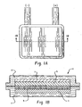
- Components of the thin flexible printed battery 1 of the within invention include a printed anode 3, a printed cathode 5, a cathode current collector 7, a separator 9 and an aqueous electrolyte contained within a flexible thin battery package, housing or enclosure 11. See Fig. 1A and Fig. 1B .
- an effective, conductive, aqueous zinc ink can be formulated and printed directly onto the surface of a nonconductive substrate without the necessity of first printing an anode current collector or otherwise supplying a conductive substrate to function as a discrete anode current collector.
- aqueous means that water is utilized as at least one solvent in the anode ink formulation.
- the source of excess zinc +2 cations is an aqueous solution of zinc acetate (Zn(OOCCH 3 )•2H 2 O) such as is available from, for example, Fisher Scientific, product designation Z20. While not wanting to be bound by theory, it is believed that the source of excess zinc +2 cations changes the conformation and aggregation of the polymer binder used in the ink formulation so that the polymer is less likely to form an insulating layer on the zinc particles, thereby improving the zinc particle to particle contact.
- the zinc powder of the zinc anode ink is commercially available from such sources as Big River Zinc, Union Miniere or Noranda, and is preferably alloyed with from 500 to 1600 ppm lead.
- the zinc is BIA zinc (a bismuth, indium and aluminum alloy) commercially available from zinc suppliers such as Noranda.
- the zinc anode ink of the within invention uses very fine zinc powder, or dust.
- the zinc dust preferably has a Microtrac particle size d(50) value of from 10 to 60 ⁇ m and is dimensioned such that the powder will pass through a 53 ⁇ m (270 mesh) sieve (USA standard).
- the d(50) value should not exceed one half of the desired ink layer thickness.
- the d(50) value of the powder component should in general not exceed 25 ⁇ m.
- PVP polyvinylpyrrolidone
- Other components of the preferred zinc ink in the carbon zinc electrochemical cell embodiment of the within invention include an appropriate binder that is compatible with the cell chemistry, including the cell electrolyte.
- an aqueous solution of polyvinylpyrrolidone (PVP) having a molecular weight of 2.0 to 4.0 million is utilized in conjunction with a source of excess zinc +2 ions, such as zinc acetate, as disclosed above.
- PVP is soluble in a zinc acetate solution but not in traditional carbon zinc electrolytes such as zinc chloride and ammonium chloride.
- PVP is commercially available from ISP Technologies, Inc. Wayne, New Jersey, product designation PVP-K120.
- the zinc ink of the within invention can further include other cell additives to produce beneficial performance attributes.
- the relatively fine particle size of the zinc employed in the zinc ink of the within invention results in increased gassing.
- a surfactant known to reduce gassing in alkaline cells has both a phosphate group and polyethylene oxide and/or polypropylene oxide chains. Such a surfactant is available commercially under the Union Carbide tradename Triton QS-44. We have discovered that surfactants of this type are even more beneficial in controlling gassing in acidic electrolytes such as LeClanche or zinc chloride electrolytes.
- a "LeClanche electrolyte" is an electrolyte containing both zinc chloride and ammonium chloride.
- the zinc ink of the within invention has sufficient conductivity so as to obviate the need for a distinct anode current collector to be printed or otherwise placed into contact with the anode formed from the zinc ink of the within invention.
- the anode formed from the zinc ink of the within invention maintains conductivity during the discharge even though the zinc is being consumed.
- the anode tab that forms the negative terminal external to the cell housing is directly connected with the zinc ink of the within invention, rather than being in electrical contact with a distinct anode collector.
- a laminate with an ethylene methacrylic or polyethylene methacrylic acid heat-sealable layer is made by Ludlow Coated Products of Homer, Louisiana.
- the appropriate laminate and associated sealing layer will be selected on the basis of, among other factors, the type of electrolyte to be used, as is known in the art.
- the impervious metallic foil layer can be any variety of metals such as, for example, aluminum, nickel, copper and stainless steel.
- the protective polymer layer is preferably a polyester or nylon, but other polymeric materials such as a polypropylene or a polyethylene could also be employed in this layer.
- the cathode assembly of a carbon zinc cell according to the within invention (current collector and electrolytic manganese dioxide, or EMD, active material) is printed onto a flexible substrate to which the cathode current collector ink will adhere with minimal or no cracking, preferably onto the sealable surface of a flexible packaging material that will be used to house the battery.
- a flexible battery housing laminate material is available for example from Pharma Center Shelbyville, product designation number 95014, as described above.
- a current collector is deposited onto the flexible polymer using a stencil, a screen or other suitable printing apparatus.
- the sealing surface of the laminate material is used as the printing surface, i.e. that surface of the material that will end up being positioned within the battery package or housing.
- the cathode current collector ink is preferably an ink formulated from materials sufficient to transfer electrons generated in the reduction of the cathode during discharge.
- the appropriate cathode current collector material will be selected based on the materials utilized in the cell, to maximize current transfer while minimizing undesirable reactions with other cell component materials, as is known in the art.
- Cells having screen printed cathode collectors of various thicknesses using PF407C ink were evaluated to determine the minimum collector thicknesses for a given application.
- the cells had stenciled EMD cathodes and screen printed zinc anodes of 112 to 125 ⁇ m (dry), achieved with multiple screen passes.
- the cathode collectors were dried at 50°C under a 26.7 Pa (2 Torr) vacuum for 16 hours. The cells were then discharged under the test protocols described below for 100 cycles, and the cells still had a closed circuit voltage of greater than .9 volts.
- Conductivity can be enhanced by the addition of carbon black in low ( ⁇ 5 weight percent) amounts.
- Other block co-polymers in the Kraton line are also suitable as binders for this ink, including styrene-butadiene -styrene materials.
- the cathode current collector ink was evaluated. A 0.0762 mm (003 inch) leaded zinc foil was used as the anode. The cathode collector and the cathode were both stenciled. The cathode dry formulation was 90 weight percent manganese dioxide, 2 weight percent Carbopol 940 and 8 weight percent KS6 graphite. The current collector wet ink formulation was 10 weight percent Kraton G1650, 34 weight percent graphite and 56 weight percent toluene. The dry thickness of the collector was between 100 and 125 microns. The cells were discharged for 100 cycles, where a cycle is defined as an 8 mA current for 16 second followed by a 60 second rest. The cell voltage remained above .9 volts.
- a metallic current collector will be more conductive than a carbon current collector, but will react with the manganese dioxide in a zinc chloride electrolyte.
- a conductive metal or metallic ink such as silver, silver ink or aluminum
- a protective conductive carbon film preferably consists of a mixture of graphite such as KS6 (20-25 weight percent), an SEBS block copolymer such as Kraton G1650 (15-18 weight percent) and toluene (56-62 weight percent).
- the protective conductive carbon coating formulation can utilize carbon black (5-10 weight percent) with Kraton G1650 (15-18 weight percent) and toluene (72-75 weight percent).
- Other block co-polymers in the Kraton line are also suitable as binders for this protective coating ink, including styrene-butadiene -styrene materials.
- Cells were evaluated using anode current collectors and cathode current collectors of silver ink with a printed protective conductive carbon ink.
- a silver was applied to the sealing surface of the flexible laminate packaging material such as described above and was cured at 70°C for one to two hours to a thickness of around 30 to 40 ⁇ m.
- the protective coating ink formulation was 18 weight percent Kraton 1650, 22 weight percent KS6 and 60 weight percent toluene, and was stenciled onto the silver and cured to a thickness of about 100 to 120 ⁇ m. The entire exposed surface of the silver ink was covered.
- Zinc anode inks as described in Table III and electrolytic manganese dioxide cathode inks as described in Table IV were then stenciled onto these protected silver collectors.
- the cells were cathode limited and had stable open circuit voltages as demonstrated in Table V below and discharged at 10 mA continuous to a cutoff voltage of .9 volts with about 35 to 40 percent cathode efficiency.
- the cathode ink is then printed onto the printed current collector.
- the cathode ink formulation is a mixture of EMD, binder and conductor in an aqueous or a non-aqueous solvent.
- the EMD powder utilized will depend on the targeted electrode thickness, desired discharge efficiency and intended application for the cell.
- Non-milled EMD with a d(50) of around 40 microns is unsuitable for a printed cathode with a targeted thickness of 50 ⁇ m or less.
- EMD with a d(50) measurement of around 1 ⁇ m can be obtained by jet-milling the EMD. Such a process is available from, for example, Sturtevant, Inc. in Hanover Massachusetts.
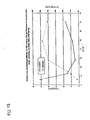
- a graphite content of from about 19 weight percent to 35 weight percent (dry formula) should be utilized. See Fig. 12 (data predicted by model developed from actual cells).
- the preferred conductive graphite is KS6 synthetic graphite as is available from Timcal America, product designation Timrex LB 1099.
- Timrex LB 1099 For the same cell thickness using a nonaqueous cathode ink formulation with a PVDF binder and the same targeted discharge current, a graphite content of from about 12 weight percent to 70 weight percent (dry formula) is preferred.
- a graphite content of from about 28 weight percent to about 49 weight percent should be utilized. See Fig. 13 (data predicted by model developed from actual cells).
- a preferred nonaqueous wet cathode ink formulation is 1.0 to 2.0 weight percent PVDF, 4.0 to 45.0 weight percent graphite and 17.0 to 66.0 weight percent EMD and 28.0 to 37.0 weight percent NMP solvent.
- An even more preferred formulation is 1.0 to 2.0 weight percent PVDF, 12.0 to 31.0 weight percent graphite and 31.0 to 51.0 weight percent EMD and 34.0 to 35.0 weight percent NMP solvent.
- a preferred aqueous wet cathode ink formulation is 1.0 to 4.0 weight percent PVP, 6.0 to 25.0 weight percent graphite and 25.0 to 43.0 weight percent EMD, balanced with water. Even more preferred is 1.5 to 2.0 weight percent PVP, 11.0-16.0 weight percent graphite and 33.0 to 38.0 weight percent EMD, balanced with water.
- the cathode ink is prepared by pre-dissolving the binder in water, grinding the solid components together (EMD and conductive additive) and adding the solids to the binder solution. The mixture is stirred and then is printed onto the existing current collector. The cathode is then cured at a slightly elevated temperature for a time sufficient to dry the ink and drive off the solvents.
- a separator is necessary to electrically isolate the electrodes while still enabling the flow of ions, as is known in the art.
- the separator can be a paper separator, a gelled separator or a printed separator.
- a coated kraft paper separator can be utilized as a separator.
- a suitable separator base paper is available commercially from Munksjo #300542 (57 g/m 2 ) and is preferably coated to a level of 20 grams per square meter (gsm) (dry) with a mixture having a dry coating composition of starch (preferably 83.6 weight percent, commercially available from, for example, Roquette LAB2469), gel (preferably 7.9 weight percent, commercially available from, for example, Courtaulds B1209), PVP (preferably 2.1 weight percent), and surfactant additive (preferably 1.4 weight percent ethyl tallow amine known commercially as Crodamet) and water (5.0 weight percent).
- starch preferably 83.6 weight percent, commercially available from, for example, Roquette LAB2469
- gel preferably 7.9 weight percent, commercially available from, for example, Courtaulds B1209
- PVP preferably 2.1 weight percent
- surfactant additive preferably 1.4 weight percent ethyl tallow amine known commercially as Crodamet
- the electrolyte is preferably an aqueous solution of zinc chloride, as is known in the art.
- Additives to prevent or reduce gassing and to encourage other performance attributes can be used, such as cetyltrimethylammonium bromide (available commercially as Cetrimide) and lead chloride. Cetyltrimethylammonium bromide is available from Aldrich, product number 855820. Cetrimide can also be introduced into the cell in a variety of ways, such as in the electrode ink formulations or as a component of a separate coating printed or otherwise applied to an electrode or separator paper surface.
- Cells were made using 0.0762 mm (003 inch) thick X 6 millimeter wide zinc foil (500 ppm lead) anodes and printed cathodes in a co-planar construction to compare their performance in a standard zinc chloride electrolyte versus the gelled Galactasol electrolyte.
- the cathode collector in all four cells was the Acheson PF407C carbon ink.
- the cathode dry formulation by weight was 2 percent PVP, 28 percent KS6 and 70 percent jet-milled Chemetals EMD.
- the gelled electrolyte cells used a mixture of 6 weight percent Galactasol in a 28 weight percent zinc chloride solution.
- the gelled electrolyte was made by gradually adding a 6 weight percent Galactasol solution to a 28 weight percent zinc chloride solution contained in a beaker. The solution was stirred with a magnet bar and then the gelled electrolyte was left at room temperature overnight to let the trapped air escape.
- the control cells used a coated kraft separator paper soaked in a 28 weight percent zinc chloride solution. The cells were subjected to a cycled discharge regimen where a cycle was defined as a discharge at 2 mA for six seconds and 0 mA for 60 seconds, and were discharged until they reached a cutoff voltage of .9 volts. Table VI further describes the cell inputs and performance data.
- Cell contacts present a design challenge for a number of reasons. It is desirable to be able to select the external contact materials without regard to the potential for unfavorable reactions between the external contacts and the materials utilized within the cell (such as electrolyte). Constraints imposed by the internal cell environment can interfere with the development of external tabs with the desired strength and current carrying properties. Further, leakage of electrolyte can be a problem with cells using aqueous electrolytes and metal structures for carrying current from the electrode to the external cell terminal. This leakage is a result at least in part of the propensity of electrolyte to travel, or "creep" along the metal surface of a current carrying structure that extends from the interior of the cell housing or package and through the sealed cell perimeter out to the external cell environment.
- a “discontinuous” current carrying system exists where two distinct structures are employed for the purpose of carrying current between an electrode and the external cell terminal.
- One structure referred to herein as a current collector, extends from the interior of the cell into the seal area and has a terminal end within the seal area or at the seal outer perimeter.
- a second external structure referred to herein as the external terminal, extends from the external environment into the seal area, or contacts a conductive adhesive or epoxy that is positioned within the seal area.
- a conductive bridge formed of direct contact between the two structures, or a conductive adhesive or epoxy that extends between the two structures, provides a pathway for current flow within the seal perimeter area.
- the "seal area” as used herein includes the area of the cell packaging or housing material that is joined together using a pressure seal or heat seal or epoxy or other means of joining two sections together.
- the current collector 13 for an electrode extends into the seal area 15, while a second metallic external terminal 17 extends into the sealing area and contacts the current collector 13 within the sealing area.
- electrical conductivity for current flow is provided by the physical contact between the internal current collector and the external terminal.
- the current collector 13 and the external terminal 17 are not in physical contact.
- Electrical conductivity is provided by an electrically conductive adhesive or epoxy 19 located at least in part within the seal area 15 and bridging the two structures.
- the conductive adhesive or epoxy 19 extends to the area external to the cell and forms the external cell contact.
- the anode and cathode external terminals or contacts are preferably printed onto a flexible nonconductive polymer substrate with a silver based conductive polymer ink such as Electrodag 479SS available from Acheson Colloids, Port Huron, Michigan.
- a silver based conductive polymer ink such as Electrodag 479SS available from Acheson Colloids, Port Huron, Michigan.
- the cathode collector is then printed onto the external cathode contact so that the collector and the external contact overlap in at least the seal area of the cell package or container.
- the anode ink is printed onto the external anode contact so that the anode and the external contact overlap in at least the seal area of the cell package or container.
- At least a portion of the seal area includes an adhesive or epoxy for joining together two surfaces of packaging material to form the cell package or housing.
- the adhesive can be activated by heat or pressure or other means as is known in the art.
- the seal area can compromise an epoxy that forms a seal by a polymerization reaction initiated chemically, thermally or using photoinitiation or encapsulation as is known in the art.
- Use of a two part conductive epoxy can accommodate delays in manufacturing by avoiding epoxy curing during the delay.
- the external tabs for the electrodes are printed onto a flexible nonconductive polymer substrate that preferably forms the battery package.
- the zinc ink is formulated and applied directly to the substrate surface.
- the shape of the electrode is selected according to the cell design for the given application, as is known in the art.
- the zinc ink is printed onto the substrate using a silk screen, stencil or other suitable printing apparatus with a pattern that allows the ink to form an area that will interface with a cathode, and an area that will overlap a portion of the tab in the area that will be sealed to form the package.
- a suitable drying and/or curing protocol is engaged, depending on the ink formulation.
- the ink for the cathode current collector is formulated and applied to a second section of flexible polymer substrate material, by stencil, screen or other suitable printing apparatus, followed by a suitable drying protocol.
- the second section of flexible polymer substrate material upon which the cathode current collector is printed may either be a section that allows for a co-planar arrangement between anode and cathode or a section that allows for a co-facial arrangement of anode and cathode.
- "co-facial" electrodes share an interfacial area between a major anode surface and a major cathode surface.
- Co-facial electrodes are to be distinguished from "co-planar" electrodes, where a major anode assembly (anode + collector, if any) surface and a major cathode assembly (cathode + collector, if any) surface lie approximately in the same plane and are printed directly or indirectly onto a single piece of substrate material.
- the cathode current collector shape is selected so as to allow for sufficient contact with the cathode ink, and preferably also forms an area that will overlap a portion of the cathode tab in the seal area.
- the current collector ink is dried and then the cathode ink is printed onto the current collector and dried.
- a separator is disposed between the anode and cathode in the case of electrodes in a co-facial arrangement. Electrolyte is introduced into the cell by way of separator paper soak up of free electrolyte or by way of a gel formulation that incorporates electrolyte or by way of electrode soak up of free electrolyte, or a combination thereof as is known in the art. The cell package or housing is then sealed together. In a preferred embodiment, the external contacts for the cell are discontinuous, as defined herein.
- the anode ink wet formulation was 9.6 percent zinc acetate dihydrate, 31.7 percent water, 1.3 percent PVP (molecular weight of 2.2 to 2.8 million) and 57.4 percent zinc dust.
- the zinc ink was made by first combining the zinc acetate dihydrate obtained from Aldrich Chemical Company with water to form an aqueous solution. PVP was added to the aqueous solution to make a viscous salt-polymer solution. Zinc dust added and the mixture was stirred until homogeneous. The zinc dust was leaded with .16 percent lead. The zinc dust had a Microtrac average volumetric particle size, or d(50) value of about 10 ⁇ m.
- the mixture was allowed to stand to achieve the appropriate thickness, about 90 to 120 minutes.
- An anode was then screen printed by hand.
- the anode substrate was the inner heat sealable surface of a flexible polymer and metal laminate packaging material available from Pharma Center Shelbyville, product number 95014.
- the laminate comprises an inner heat sealable ethylene acrylic acid layer, a layer of aluminum, and an outer protective polymer layer.
- Four to five wet passes over the screen resulted in an anode 39 millimeters X 37 millimeters with a thickness of about .087 millimeters.
- the anode was dried at 70°C for five minutes.
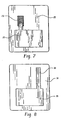
- An anode tab 23 made of 0.0508mm (002 inch) thick zinc mesh was adhesively attached to the substrate 25 for place holding until the anode ink 27 was printed onto the substrate, overlapping one end of the tab and thereby affixing it to the substrate. See Fig. 7 , illustrating the zinc mesh external tab 23 and the anode ink 27, prior to trimming the part for assembly into a cell.
- the anode tab 23 could also be printed silver ink.
- the cathode current collector ink was a carbon ink provided by Acheson Colloids, product number PF407C.
- the cathode collector 29 was stenciled onto the heat sealable surface of a discrete piece of the same laminate material 31 used for the anode substrate.
- the resulting collector that would contact the printed cathode was 40 millimeters X 38 millimeters with a thickness of about .052 millimeters.
- a tab extension 33 was stenciled using the same cathode collector ink and extending from the collector. See Fig. 8 .
- the cathode collector and tab extension was cured at 50 °C for 16 hours under vacuum to drive off the solvents used in the ink.
- a coated kraft separator paper with a thickness of about 95 ⁇ m is used.
- the separator base paper is available from Munksjo #300542, and is coated at a level of 20 grams per square meter (gsm) with a mixture of starch (83.6 weight percent available from Roquette LAB2469), gel (7.9 weight percent available from Courtlands B1209), PVP (2.1 weight percent), surfactant (1.4 weight percent ethyl tallow amine known commercially as Crodamet) and water (5 weight percent).
- the paper was wetted with the cell electrolyte, a 28 percent by weight zinc chloride solution with 1000 ppm Cetrimide BP (cetyl trimethyl ammonium bromide, available from ABA Chemical Ltd., Cheshire, England) and 600 ppm lead chloride added to the solution.
- the electrolyte solution is filtered to remove solids prior to use.
- the electrode surfaces were also wetted with the electrolyte so that a total of between .7 and .8 grams of electrolyte was incorporated into the cell.
- the separator was placed onto either electrode and oriented such that the coated side of the separator faced the zinc anode.
- the electrode substrates were trimmed to an appropriate size and the cell was heat sealed around the perimeter, such that the electrode tabs extended beyond the heat seal to the exterior of the cell package. Since the packaging laminate, upon trimming, exposed an edge of the inner aluminum foil layer, a strip of polyethylene was wrapped around the anode tab to insure against shorting between the aluminum and the zinc ink.
- Two of these cells were connected in series to a printed circuit and powered an LED and sound card application with a current drain of 8 mA.
- several of these cells were discharged for at least 100 cycles, where a cycle is defined as 8 mA for 16 seconds on and 0 mA (no drain) for 60 seconds.
- Co-planar electrode assembly cells were constructed according to this example.
- An anode was printed using the same anode ink formulation and substrate as in Example 1, and a 0.0508mm (002 inch) thick zinc mesh anode current collector as in Example 1 was affixed to the substrate in the same manner as in Example 1.
- the anode 34 was screen printed to a size of 50.4 millimeters X 6.8 millimeters with an average thickness of .109 millimeters.
- the cathode current collector and cathode were stenciled using the same formulation as in Example 1 onto the same substrate as the anode to form a co-planar electrode arrangement.
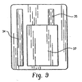
- the cathode current collector 35 was stenciled to a size of 40 millimeters X 27 millimeters X .036 millimeters, while the cathode ink 37 was stenciled onto the current collector with a thickness of .166 millimeters. See Fig. 9 .
- the gap between the cathode and the anode was 2.0 millimeters.
- the electrode surfaces were wetted up with the same electrolyte as in Example 1, and the same separator paper as in Example 1 was introduced to provide an electrolyte soakup such that a total of .6 to .7 grams of electrolyte was introduced into the cell.
- the separator paper in this co-planar arrangement is sized to cover both the anode and the cathode.
- the substrate was trimmed to the appropriate size and a second piece of the packaging material was placed over the first so that the heat sealable surfaces face each other, as in Example 1, and the two are sealed together around the cell perimeter, exposing the tabs for the anode and cathode to the external environment of the cell.
- Two cells were connected in series to a printed circuit and powered a sound card application with a current drain of 2 mA.
- several cells were discharged for at least 100 cycles, where a cycle is defined as 2mA for 6 seconds on and 0 mA (no drain) for 60 seconds.
- Co-facial electrode assembly cells were constructed as follows. A zinc mesh anode was utilized in the cells of this example, consisting of a 0.127 ⁇ m (005 inch) thick piece of zinc mesh available from Delkar Corporation. The mesh was cut to 39 millimeters X 37 millimeters and adhered to the same substrate material as in Examples 1 and 2. The anode current collector was formed from this zinc mesh also and adhered to the substrate in the same manner.
- the cathode current collector for the cells of this example used the same carbon ink as in Example 1, and was stenciled as in Example 1 to a size of 40 millimeters X 38 millimeters with an average thickness of .052 millimeters on the same substrate material as in Example 1.
- the cathode ink was the same ink formulation as in Example 1, and was stenciled onto the collector as in Example 1 to an average thickness of .149 millimeters.
- the same separator material was used as in Example 1 and the same electrolyte as in Example 1 was introduced into the cell by wetting the cathode surface and the separator so as to introduce an average of .743 grams of electrolyte into the cell. The two substrates were then joined together by heat sealing.
- Three cells were connected in series to a printed circuit and powered an electroluminescent display with a current drain of about 15 mA.
- Cells were constructed utilizing an aqueous zinc ink formulation with a co-solvent system in accordance with the within invention.
- the cells had a printed zinc anode, a printed manganese dioxide cathode, a zinc chloride electrolyte and a coated kraft paper separator as described above.
- the electrolyte was a 28 weight percent zinc chloride solution to which 600 ppm lead chloride and 1000 ppm cetyltrimethylammoniium bromide (available from Aldrich) was added. This solution was filtered to remove solids prior to introduction into the cells.
- a co-solvent system comprising water and NMP was utilized with a PVP binder in the zinc ink formulation.
- the anode zinc ink general formulation was 8.6 grams Union Miniere zinc dust (1600 ppm lead) with a laser median diameter of 10.2 ⁇ m, .2 grams PVP K-120, 4.5 mL 1.4 molar zinc acetate aqueous solution and .5 mL NMP.
- the cathode ink general formulation was 7 grams Chemetals jet-milled EMD (d(50) ⁇ 1 ⁇ m, d(90) ⁇ 3 ⁇ m,
- CCV at the 100 th cycle is 1.16V *0.4371** 0.1820** Pass 15mA pulse test for 100 cycles @ 16sec. on/60 sec. off.
- CCV at the 100 th cycle is 1.00V *includes zinc for external contact tab; same printed zinc ink as was used for the anode **separator paper coating included cetyltrimethylammonium bromide available commercially as Cetrimide
- a printed cell is assembled as follows: initially, a cathode collector is printed onto the sealing surface of a single sheet of a metal laminated packaging material available from Pharma Center Shelbyville, product number 95014, and dried.
- the cathode current collector is Electrodag PF-407C, a carbon polymer ink available from Acheson.
- the cathode collector is printed to a dry thickness of 36 ⁇ m X 27 millimeters X 40 millimeters.
- silver external tabs for the anode and cathode are printed onto the sealing surface of the same sheet of metal laminate and dried. The cathode tab overlaps the cathode current collector ink already deposited onto the metal laminate surface.
- the silver ink is Acheson 479SS, and each tab has a dry dimension of 32.3 millimeters X 11.0 millimeters X 10.0 ⁇ m thick, and is separated from the other by 11 millimeters.
- An anode is printed on the same laminate sheet.
- the anode is a zinc ink with a wet composition of 57.35 weight percent Union Miniere zinc dust with a laser median diameter of 10 ⁇ m as reported by the manufacturer, 1.33 weight percent PVP, 31.74 weight percent water and 9.58 weight percent zinc acetate available from Aldrich as Zn(OOOCH 3 ) 2 ⁇ 2H 2 O.
- the ink is made by first mixing the aqueous zinc acetate solution first, then dissolving the PVP into the solution, and finally adding the zinc dust and stirring until homogeneously mixed.
- the anode is printed onto the substrate material, overlapping the silver anode tab already deposited on the sealing surface of the metal laminate to a dry thickness of 100 ⁇ m X 6 millimeters X 38.6 millimeters.
- One of skill in the art will recognize that the order of printing can be changed, and the silver external tabs can be printed initially directly onto the sealing surface.without departing from the scope of the within invention.
- Coated kraft separator paper with a dry thickness of .089 to .114 millimeters X 40 millimeters X 43.6 millimeters is placed over the electrodes.
- the separator base paper is available from Munksjo #300542, and is coated at a level of 20 grams per square meter (gsm) with a mixture of starch (83.6 weight percent available from Roquette LAB2469), gel (7.9 weight percent available from Courtlands B1209), PVP (2.1 weight percent), surfactant (1.4 weight percent ethyl tallow amine known commercially as Crodamet) and water (5 weight percent).
- a second sheet of laminate packaging material is placed over the electrode assembly and the package is trimmed and heat sealed along three edges.
- a circuit 45 is screen printed to a thickness of 8-12 ⁇ m onto a 0.254 mm (010 inch) thick polyester film 47 available from Melinex #454 (see Fig. 12 ) using the Acheson silver ink (Electrodag 479SS) in a solvent of diethylene glycol monoethyl ether acetate and dried.
- a 200,000 ohm resistor 49 is printed to a thickness of 10 to 15 ⁇ m onto the circuit using Acheson carbon ink (Minico M 301401 RS) in a bisolvent of ethylene glycol monobutyl ether acetate and isophorene (see Fig. 10 ).
- a sound chip 51 available from Holtek (HT81R03) and a piezoelectric speaker 53 available from Star Micronics (QMB 105PX) are affixed to the circuit using silver epoxy available from Circuit Works (CW 2400).
- a switch is assembled using zinc foil on double stick tape and connected to the circuit.
- Two cells 55, 57 are connected to the circuit using the silver epoxy and the device is completed and ready for operation. See Fig. 11 .
Landscapes
- Chemical & Material Sciences (AREA)
- Chemical Kinetics & Catalysis (AREA)
- Electrochemistry (AREA)
- General Chemical & Material Sciences (AREA)
- Engineering & Computer Science (AREA)
- Manufacturing & Machinery (AREA)
- Inorganic Chemistry (AREA)
- Materials Engineering (AREA)
- Composite Materials (AREA)
- Primary Cells (AREA)
- Battery Electrode And Active Subsutance (AREA)
- Cell Electrode Carriers And Collectors (AREA)
- Sealing Battery Cases Or Jackets (AREA)
- Battery Mounting, Suspending (AREA)
- Hybrid Cells (AREA)
- Cell Separators (AREA)
Claims (10)
- Kohle-Zink-Batterie, umfassend eine Zinkanode, die direkt auf einen ersten Abschnitt eines flexiblen nichtleitenden Substratmaterials gedruckt ist, ein abgedichtetes Gehäuse und einen gelierten Elektrolyten, der Zinkchlorid, Wasser und ein Geliermittel umfasst, wobei die Anode und der gelierte Elektrolyt in dem Gehäuse enthalten sind, dadurch gekennzeichnet, dass die Zinkanode durch direktes Drucken einer wässrigen Anodenzubereitung, die Zink, Zinkacetat und Polyvinylpyrrolidon mit einem Molekulargewicht von 2,0 bis 4,0 Millionen umfasst, auf den ersten Abschnitt des flexiblen nichtleitenden Substratmaterials erhältlich ist.
- Batterie gemäß Anspruch 1, wobei das Geliermittel nichtionische oder anionische Derivate und natürliches Guarkernmehl umfasst.
- Batterie gemäß Anspruch 1, wobei das nichtleitende Substratmaterial ein Polymermaterial ist.
- Batterie gemäß Anspruch 1, wobei das abgedichtete Gehäuse ein dichtes Gehäuse ist.
- Batterie gemäß Anspruch 1, wobei das abgedichtete Gehäuse ein flexibles Verpackungsmaterial umfasst.
- Batterie gemäß Anspruch 1, die weiterhin einen Stromabnehmer und einen Dichtungsbereich umfasst, wobei das abgedichtete Gehäuse ein flexibles nichtleitendes Material umfasst und sich der Stromabnehmer durch den Dichtungsbereich des abgedichteten Gehäuses erstreckt.
- Batterie gemäß Anspruch 1, wobei das abgedichtete Gehäuse flexibel ist und von dem flexiblen nichtleitenden Substrat gebildet wird.
- Batterie gemäß Anspruch 1, wobei das Polyvinylpyrrolidon ein Molekulargewicht von 2,2 bis 2,80 Millionen hat.
- Batterie gemäß Anspruch 1, wobei die wässrige Anodenzubereitung ein Tensid umfasst, das eine Phosphatgruppe und eine Polyethylenoxid-und/oder Polypropylenoxidkette aufweist.
- Batterie gemäß Anspruch 1, wobei der Elektrolyt Cetyltrimethylammoniumbromid und Bleichlorid umfasst.
Priority Applications (1)
| Application Number | Priority Date | Filing Date | Title |
|---|---|---|---|
| EP10178889A EP2276092B1 (de) | 2002-02-12 | 2002-12-17 | Flexible Dünnschichtbatterie mit Gelelektrolyt und Verfahren zu ihrer Herstellung |
Applications Claiming Priority (17)
| Application Number | Priority Date | Filing Date | Title |
|---|---|---|---|
| US35658402P | 2002-02-12 | 2002-02-12 | |
| US35640702P | 2002-02-12 | 2002-02-12 | |
| US35621302P | 2002-02-12 | 2002-02-12 | |
| US35640602P | 2002-02-12 | 2002-02-12 | |
| US35626602P | 2002-02-12 | 2002-02-12 | |
| US35658302P | 2002-02-12 | 2002-02-12 | |
| US35624702P | 2002-02-12 | 2002-02-12 | |
| US35623602P | 2002-02-12 | 2002-02-12 | |
| US356247P | 2002-02-12 | ||
| US356213P | 2002-02-12 | ||
| US356236P | 2002-02-12 | ||
| US356583P | 2002-02-12 | ||
| US356407P | 2002-02-12 | ||
| US356584P | 2002-02-12 | ||
| US356406P | 2002-02-12 | ||
| US356266P | 2002-02-12 | ||
| PCT/US2002/040174 WO2003069700A2 (en) | 2002-02-12 | 2002-12-17 | Flexible thin printed battery with gelled electrolyte and method of manufacturing same |
Related Child Applications (1)
| Application Number | Title | Priority Date | Filing Date |
|---|---|---|---|
| EP10178889.1 Division-Into | 2010-09-23 |
Publications (2)
| Publication Number | Publication Date |
|---|---|
| EP1485960A2 EP1485960A2 (de) | 2004-12-15 |
| EP1485960B1 true EP1485960B1 (de) | 2011-06-29 |
Family
ID=27739553
Family Applications (2)
| Application Number | Title | Priority Date | Filing Date |
|---|---|---|---|
| EP10178889A Expired - Lifetime EP2276092B1 (de) | 2002-02-12 | 2002-12-17 | Flexible Dünnschichtbatterie mit Gelelektrolyt und Verfahren zu ihrer Herstellung |
| EP02806817A Expired - Lifetime EP1485960B1 (de) | 2002-02-12 | 2002-12-17 | Flexible dünne bedruckte batterie |
Family Applications Before (1)
| Application Number | Title | Priority Date | Filing Date |
|---|---|---|---|
| EP10178889A Expired - Lifetime EP2276092B1 (de) | 2002-02-12 | 2002-12-17 | Flexible Dünnschichtbatterie mit Gelelektrolyt und Verfahren zu ihrer Herstellung |
Country Status (11)
| Country | Link |
|---|---|
| US (6) | US7348096B2 (de) |
| EP (2) | EP2276092B1 (de) |
| JP (2) | JP5021889B2 (de) |
| KR (2) | KR100980355B1 (de) |
| CN (1) | CN100367539C (de) |
| AT (1) | ATE515069T1 (de) |
| AU (1) | AU2002367630A1 (de) |
| CA (1) | CA2513454C (de) |
| HK (2) | HK1071231A1 (de) |
| IL (1) | IL163141A (de) |
| WO (1) | WO2003069700A2 (de) |
Cited By (2)
| Publication number | Priority date | Publication date | Assignee | Title |
|---|---|---|---|---|
| US10811694B2 (en) | 2016-01-26 | 2020-10-20 | Schreiner Group Gmbh & Co. Kg | Film structure for a battery for dispensing on a round body |
| US10854889B2 (en) | 2016-01-26 | 2020-12-01 | Schreiner Group Gmbh & Co. Kg | Film structure for a battery for providing on a round body |
Families Citing this family (191)
| Publication number | Priority date | Publication date | Assignee | Title |
|---|---|---|---|---|
| US6699265B1 (en) | 2000-11-03 | 2004-03-02 | Cardiac Pacemakers, Inc. | Flat capacitor for an implantable medical device |
| US6687118B1 (en) | 2000-11-03 | 2004-02-03 | Cardiac Pacemakers, Inc. | Flat capacitor having staked foils and edge-connected connection members |
| US6509588B1 (en) | 2000-11-03 | 2003-01-21 | Cardiac Pacemakers, Inc. | Method for interconnecting anodes and cathodes in a flat capacitor |
| US7456077B2 (en) | 2000-11-03 | 2008-11-25 | Cardiac Pacemakers, Inc. | Method for interconnecting anodes and cathodes in a flat capacitor |
| EP2276092B1 (de) * | 2002-02-12 | 2013-02-13 | Eveready Battery Company, Inc. | Flexible Dünnschichtbatterie mit Gelelektrolyt und Verfahren zu ihrer Herstellung |
| US7320845B2 (en) * | 2002-05-24 | 2008-01-22 | The Intertech Group, Inc. | Printed battery |
| US6979513B2 (en) * | 2002-06-28 | 2005-12-27 | Firefly Energy Inc. | Battery including carbon foam current collectors |
| US7951479B2 (en) | 2005-05-11 | 2011-05-31 | Cardiac Pacemakers, Inc. | Method and apparatus for porous insulative film for insulating energy source layers |
| US7479349B2 (en) | 2002-12-31 | 2009-01-20 | Cardiac Pacemakers, Inc. | Batteries including a flat plate design |
| US8691418B2 (en) * | 2003-02-07 | 2014-04-08 | Cardiac Pacemakers, Inc. | Insulative member on battery cathode |
| US7791860B2 (en) * | 2003-07-09 | 2010-09-07 | Maxwell Technologies, Inc. | Particle based electrodes and methods of making same |
| US20070122698A1 (en) | 2004-04-02 | 2007-05-31 | Maxwell Technologies, Inc. | Dry-particle based adhesive and dry film and methods of making same |
| US7968233B2 (en) | 2004-02-18 | 2011-06-28 | Solicore, Inc. | Lithium inks and electrodes and batteries made therefrom |
| US7820329B2 (en) * | 2004-03-18 | 2010-10-26 | The Procter & Gamble Company | Wafer alkaline cell |
| US7776468B2 (en) * | 2004-03-18 | 2010-08-17 | The Gillette Company | Wafer alkaline cell |
| US7413828B2 (en) * | 2004-03-18 | 2008-08-19 | The Gillette Company | Wafer alkaline cell |
| US7531271B2 (en) * | 2004-03-18 | 2009-05-12 | The Gillette Company | Wafer alkaline cell |
| US20060246343A1 (en) * | 2004-04-02 | 2006-11-02 | Maxwell Technologies, Inc. | Dry particle packaging systems and methods of making same |
| US8722235B2 (en) * | 2004-04-21 | 2014-05-13 | Blue Spark Technologies, Inc. | Thin printable flexible electrochemical cell and method of making the same |
| US7632587B2 (en) * | 2004-05-04 | 2009-12-15 | Angstrom Power Incorporated | Electrochemical cells having current-carrying structures underlying electrochemical reaction layers |
| TWI236175B (en) | 2004-05-14 | 2005-07-11 | Antig Tech Co Ltd | Secondary battery |
| US20060257736A1 (en) * | 2004-05-31 | 2006-11-16 | Nissan Motor Co., Ltd. | Electrode, battery, and method of manufacturing the same |
| KR101119090B1 (ko) * | 2004-06-24 | 2012-03-16 | 엘지전자 주식회사 | 식기 세척기의 이물 고착 방지장치 및 그 방법 |
| JP2008503298A (ja) * | 2004-06-25 | 2008-02-07 | コーニンクレッカ フィリップス エレクトロニクス エヌ ヴィ | 表面コイル用の集積された電力供給 |
| US20060007049A1 (en) * | 2004-07-01 | 2006-01-12 | Zvi Nitzan | Battery-assisted backscatter RFID transponder |
| US7180727B2 (en) | 2004-07-16 | 2007-02-20 | Cardiac Pacemakers, Inc. | Capacitor with single sided partial etch and stake |
| US8231988B2 (en) * | 2005-02-09 | 2012-07-31 | University Of Iowa Research Foundation | Batteries and battery components with magnetically modified manganese dioxide |
| EP1849206B1 (de) * | 2005-02-15 | 2013-01-09 | Lg Chem, Ltd. | Lithium-sekundärbatterie mit einem ammoniumverbindungen enthaltenden elektrolyt |
| US20060210877A1 (en) * | 2005-03-15 | 2006-09-21 | Rechargable Battery Corporation | Flexible pasted anode, primary cell with pasted anode, and method for making same |
| US8029927B2 (en) * | 2005-03-22 | 2011-10-04 | Blue Spark Technologies, Inc. | Thin printable electrochemical cell utilizing a “picture frame” and methods of making the same |
| DE102005017682A1 (de) * | 2005-04-08 | 2006-10-12 | Varta Microbattery Gmbh | Galvanisches Element |
| US20060247715A1 (en) * | 2005-04-29 | 2006-11-02 | Youker Nick A | Method and apparatus for an implantable pulse generator with a stacked battery and capacitor |
| US8722233B2 (en) | 2005-05-06 | 2014-05-13 | Blue Spark Technologies, Inc. | RFID antenna-battery assembly and the method to make the same |
| US20090045916A1 (en) * | 2005-06-30 | 2009-02-19 | Zvi Nitzan | Battery-assisted backscatter RFID transponder |
| US20080272890A1 (en) * | 2005-06-30 | 2008-11-06 | Zvi Nitzan | Battery-assisted backscatter RFID transponder |
| RU2008107980A (ru) * | 2005-08-01 | 2009-09-10 | Стора Энсо Аб (Se) | Упаковка и способ ее закрытия и открытия |
| WO2007015237A1 (en) * | 2005-08-01 | 2007-02-08 | Powerid Ltd. | Intermediate attachment mechanism and use thereof in rfid transponder |
| US20070024425A1 (en) * | 2005-08-01 | 2007-02-01 | Zvi Nitzan | Active capacitive coupling RFID device, system and method of production thereof |
| CN101401231B (zh) * | 2006-03-08 | 2011-08-03 | 株式会社Lg化学 | 性能改进的锂二次电池 |
| US20080000882A1 (en) * | 2006-06-01 | 2008-01-03 | Vanderlick Stephen W | Method and apparatus for a foil to control heat flow from welding a device case |
| US8874214B2 (en) * | 2006-08-28 | 2014-10-28 | Cardiac Pacemakers, Inc. | Implantable pulse generator with a stacked capacitor, battery, and electronics |
| US7879488B2 (en) * | 2006-08-28 | 2011-02-01 | Cardiac Pacemakers, Inc. | Apparatus and method for a power source casing with a stepped bevelled edge |
| US8049807B2 (en) * | 2006-09-05 | 2011-11-01 | Olympus Imaging Corp. | Digital camera and dust reduction apparatus for digital camera |
| US20080070103A1 (en) * | 2006-09-19 | 2008-03-20 | Caleb Technology Corporation | Activation of Anode and Cathode in Lithium-Ion Polymer Battery |
| US20080070104A1 (en) * | 2006-09-19 | 2008-03-20 | Caleb Technology Corporation | Forming Polymer Electrolyte Coating on Lithium-Ion Polymer Battery Electrode |
| US7527894B2 (en) | 2006-09-19 | 2009-05-05 | Caleb Technology Corporation | Identifying defective electrodes in lithium-ion polymer batteries |
| US20080070108A1 (en) * | 2006-09-19 | 2008-03-20 | Caleb Technology Corporation | Directly Coating Solid Polymer Composite Having Edge Extensions on Lithium-Ion Polymer Battery Electrode Surface |
| US7965180B2 (en) | 2006-09-28 | 2011-06-21 | Semiconductor Energy Laboratory Co., Ltd. | Wireless sensor device |
| US20080096074A1 (en) * | 2006-10-23 | 2008-04-24 | Eveready Battery Company, Inc. | Electrochemical air cell batteries with air flow channels |
| US7695840B2 (en) * | 2006-12-08 | 2010-04-13 | Eveready Battery Co., Inc. | Electrochemical cell having a deposited gas electrode |
| FI20070107A0 (fi) * | 2007-02-06 | 2007-02-06 | Enfucell Oy | Ohutparisto ja menetelmä ohutpariston valmistamiseksi |
| FI121611B (fi) * | 2007-02-06 | 2011-01-31 | Enfucell Oy | Ohutparisto ja menetelmä ohutpariston valmistamiseksi |
| CN101802848A (zh) | 2007-07-18 | 2010-08-11 | 蓝色火花科技有限公司 | 集成电子器件及其制造方法 |
| CN101849303B (zh) * | 2007-09-10 | 2013-06-12 | 麦德托尼克公司 | 印刷电极沿至少两个维度的特性控制 |
| FI120475B (fi) * | 2007-09-24 | 2009-10-30 | Enfucell Oy | Ohutparisto, jonka käyttöikä on pidempi |
| US7830646B2 (en) * | 2007-09-25 | 2010-11-09 | Ioxus, Inc. | Multi electrode series connected arrangement supercapacitor |
| US8790842B2 (en) | 2007-09-25 | 2014-07-29 | Societe Bic | Fuel cell systems including space-saving fluid plenum and related methods |
| DE102007059768A1 (de) * | 2007-12-12 | 2009-06-18 | Li-Tec Vermögensverwaltungs GmbH | Stromableiter für eine galvanische Zelle |
| CN101946347A (zh) | 2007-12-19 | 2011-01-12 | 蓝色火花科技有限公司 | 高电流薄电化学电池单元及其制造方法 |
| JP5798323B2 (ja) * | 2008-02-29 | 2015-10-21 | ソシエテ ビックSociete Bic | 電気化学電池アレイ、電気化学システムおよびそれに関する方法 |
| US8411413B2 (en) | 2008-08-28 | 2013-04-02 | Ioxus, Inc. | High voltage EDLC cell and method for the manufacture thereof |
| US20090279230A1 (en) * | 2008-05-08 | 2009-11-12 | Renewable Energy Development, Inc. | Electrode structure for the manufacture of an electric double layer capacitor |
| US8906534B2 (en) * | 2008-05-28 | 2014-12-09 | Taiwan Semiconductor Manufacturing Company, Ltd. | Stacked multi-cell battery concept |
| KR101503458B1 (ko) * | 2008-06-25 | 2015-03-18 | 삼성전자주식회사 | 유연성이 개선된 이차전지 |
| KR101391934B1 (ko) * | 2008-07-09 | 2014-05-07 | 리-텍 배터리 게엠베하 | 전기화학 전지용 전류 집전체 |
| EP2335306A4 (de) * | 2008-09-08 | 2012-03-28 | Enfucell Oy Ltd | Anode und herstellungsverfahren für eine anode |
| TW201027821A (en) * | 2008-12-23 | 2010-07-16 | Basf Se | Nonrechargeable thin-film batteries having anionically functionalized polymers as separators |
| TW201029242A (en) | 2008-12-23 | 2010-08-01 | Basf Se | Nonrechargeable thin-film batteries having cationically functionalized polymers as separators |
| WO2011019142A2 (ko) * | 2009-08-14 | 2011-02-17 | 주식회사 엘지화학 | 접착력이 우수한 이차전지용 바인더 |
| AT509408B1 (de) * | 2010-02-03 | 2012-03-15 | Univ Linz | Galvanische zelle |
| GB2477552B (en) * | 2010-02-08 | 2016-01-27 | Qinetiq Ltd | Thin electrochemical cell |
| US8974973B2 (en) * | 2010-05-27 | 2015-03-10 | Wing Fai Leung | Starch-based battery system |
| CN103181016B (zh) * | 2010-09-13 | 2016-06-22 | 加利福尼亚大学董事会 | 离子凝胶电解质、储能设备及其制造方法 |
| US20120171547A1 (en) * | 2010-12-07 | 2012-07-05 | Thin Profile Technologies | Printed battery using non-aqueous electrolyte and battery packaging |
| EP2465415B1 (de) * | 2010-12-20 | 2013-07-03 | General Electric Company | Biomedizinische Einweg-Sensoren |
| US10451897B2 (en) | 2011-03-18 | 2019-10-22 | Johnson & Johnson Vision Care, Inc. | Components with multiple energization elements for biomedical devices |
| JP2012209048A (ja) * | 2011-03-29 | 2012-10-25 | Asahi Chem Res Lab Ltd | 印刷電池 |
| US8989821B2 (en) * | 2011-08-31 | 2015-03-24 | Apple Inc. | Battery configurations for electronic devices |
| US9027242B2 (en) * | 2011-09-22 | 2015-05-12 | Blue Spark Technologies, Inc. | Cell attachment method |
| US9502730B2 (en) * | 2011-11-30 | 2016-11-22 | The Regents Of The University Of California | Printed biofuel cells |
| US9343716B2 (en) | 2011-12-29 | 2016-05-17 | Apple Inc. | Flexible battery pack |
| US8857983B2 (en) | 2012-01-26 | 2014-10-14 | Johnson & Johnson Vision Care, Inc. | Ophthalmic lens assembly having an integrated antenna structure |
| WO2013177202A1 (en) | 2012-05-21 | 2013-11-28 | Blue Spark Technologies, Inc. | Multi-cell battery |
| US10396365B2 (en) | 2012-07-18 | 2019-08-27 | Printed Energy Pty Ltd | Diatomaceous energy storage devices |
| US9548511B2 (en) | 2012-07-18 | 2017-01-17 | Nthdegree Technologies Worldwide Inc. | Diatomaceous energy storage devices |
| CN104584160B (zh) | 2012-07-18 | 2018-03-23 | 印制能源技术有限公司 | 能量储存装置与用于印刷薄膜的墨水 |
| US9812680B2 (en) | 2012-08-30 | 2017-11-07 | Apple Inc. | Low Z-fold battery seal |
| US9520598B2 (en) | 2012-10-10 | 2016-12-13 | Nthdegree Technologies Worldwide Inc. | Printed energy storage device |
| US9397341B2 (en) | 2012-10-10 | 2016-07-19 | Nthdegree Technologies Worldwide Inc. | Printed energy storage device |
| WO2014070254A1 (en) | 2012-11-01 | 2014-05-08 | Blue Spark Technologies, Inc. | Body temperature logging patch |
| US9136510B2 (en) | 2012-11-26 | 2015-09-15 | Apple Inc. | Sealing and folding battery packs |
| EP2926401B1 (de) | 2012-11-27 | 2017-07-05 | Blue Spark Technologies, Inc. | Batteriezellenaufbau |
| US20140199572A1 (en) * | 2013-01-17 | 2014-07-17 | Sensormatic Electronics, LLC | Film-based battery holder |
| US10840536B2 (en) | 2013-02-06 | 2020-11-17 | The Board Of Trustees Of The University Of Illinois | Stretchable electronic systems with containment chambers |
| US9613911B2 (en) | 2013-02-06 | 2017-04-04 | The Board Of Trustees Of The University Of Illinois | Self-similar and fractal design for stretchable electronics |
| KR20150125946A (ko) * | 2013-02-06 | 2015-11-10 | 더 보오드 오브 트러스티스 오브 더 유니버시티 오브 일리노이즈 | 인장성의 전자장치에 대한 자기 유사형 및 프랙탈 설계 |
| US10497633B2 (en) | 2013-02-06 | 2019-12-03 | The Board Of Trustees Of The University Of Illinois | Stretchable electronic systems with fluid containment |
| FR3007582B1 (fr) * | 2013-06-24 | 2015-06-26 | Inst Polytechnique Grenoble | Procede d'impression ou de depot par atomisation pour la preparation d'une electrode flexible supportee et la fabrication d'une batterie lithium-ion |
| US9786926B2 (en) * | 2013-07-17 | 2017-10-10 | Printed Energy Pty Ltd | Printed silver oxide batteries |
| WO2015030525A1 (ko) * | 2013-08-29 | 2015-03-05 | 주식회사 엘지화학 | 아연 공기 전지용 전해액 및 이를 포함하는 아연 공기 전지 |
| CN105765008A (zh) * | 2013-11-13 | 2016-07-13 | R.R.当纳利父子公司 | 电池 |
| US9593969B2 (en) | 2013-12-27 | 2017-03-14 | Apple Inc. | Concealed electrical connectors |
| US11302987B2 (en) | 2014-10-16 | 2022-04-12 | Lat Enterprises | Material for dissipating heat from and/or reducing heat signature of electronic devices and clothing |
| US10944140B2 (en) | 2014-01-15 | 2021-03-09 | Lat Enterprises, Inc. | Wearable and replaceable pouch or skin for holding a portable battery pack |
| US10476054B2 (en) | 2014-10-16 | 2019-11-12 | Lat Enterprises, Inc. | Portable battery pack comprising a battery enclosed by a wearable and replaceable pouch or skin |
| US10991992B2 (en) | 2014-01-15 | 2021-04-27 | Lat Enterprises, Inc. | System for supplying power to a portable battery using at least one solar panel |
| US12088244B2 (en) | 2014-01-15 | 2024-09-10 | Lat Enterprises, Inc. | System for supplying power to at least one power consuming device using rechargeable battery |
| US11876354B2 (en) | 2014-01-15 | 2024-01-16 | Lat Enterprises, Inc. | Wearable and replaceable pouch or skin for holding a portable battery pack |
| US11462649B2 (en) | 2014-10-16 | 2022-10-04 | Lat Enterprises, Inc. | Portable power case |
| US11750149B2 (en) | 2014-01-15 | 2023-09-05 | Lat Enterprises, Inc. | Foldable solar panel |
| US10727457B2 (en) | 2014-01-15 | 2020-07-28 | Lat Enterprises, Inc. | System for supplying power to a portable battery using at least one solar panel |
| US10531590B2 (en) | 2014-10-16 | 2020-01-07 | Lat Enterprises, Inc. | System for supplying power to at least one power distribution and data hub using a portable battery pack |
| US11996803B2 (en) | 2014-01-15 | 2024-05-28 | Lat Enterprises, Inc. | Foldable solar panel |
| US11025075B2 (en) | 2014-10-16 | 2021-06-01 | Lat Enterprises, Inc. | Portable power case with heat-resistant material |
| US11304500B2 (en) | 2014-01-15 | 2022-04-19 | Lat Enterprises, Inc. | Wearable and replaceable pouch or skin for holding a portable battery pack |
| US9479007B1 (en) | 2014-02-21 | 2016-10-25 | Apple Inc. | Induction charging system |
| US20150255776A1 (en) | 2014-03-06 | 2015-09-10 | Apple Inc. | Battery Pack System |
| US9455582B2 (en) | 2014-03-07 | 2016-09-27 | Apple Inc. | Electronic device and charging device for electronic device |
| CN103824997B (zh) * | 2014-03-20 | 2016-12-07 | 常州恩福赛印刷电子有限公司 | 一种薄型储能装置及制作工艺 |
| US9806299B2 (en) | 2014-04-08 | 2017-10-31 | International Business Machines Corporation | Cathode for thin film microbattery |
| AU2015292830A1 (en) * | 2014-07-21 | 2017-01-19 | Flexel, Llc | Flexible micro-battery |
| US10879503B2 (en) | 2014-07-21 | 2020-12-29 | Johnson & Johnson Vision Care, Inc. | Methods for the manufacture of flexible microbatteries |
| US10105082B2 (en) | 2014-08-15 | 2018-10-23 | International Business Machines Corporation | Metal-oxide-semiconductor capacitor based sensor |
| US9508566B2 (en) | 2014-08-15 | 2016-11-29 | International Business Machines Corporation | Wafer level overmold for three dimensional surfaces |
| US9899700B2 (en) | 2014-08-21 | 2018-02-20 | Johnson & Johnson Vision Care, Inc. | Methods to form biocompatible energization elements for biomedical devices comprising laminates and deposited separators |
| US10361405B2 (en) | 2014-08-21 | 2019-07-23 | Johnson & Johnson Vision Care, Inc. | Biomedical energization elements with polymer electrolytes |
| US9923177B2 (en) | 2014-08-21 | 2018-03-20 | Johnson & Johnson Vision Care, Inc. | Biocompatibility of biomedical energization elements |
| US10361404B2 (en) | 2014-08-21 | 2019-07-23 | Johnson & Johnson Vision Care, Inc. | Anodes for use in biocompatible energization elements |
| US10381687B2 (en) | 2014-08-21 | 2019-08-13 | Johnson & Johnson Vision Care, Inc. | Methods of forming biocompatible rechargable energization elements for biomedical devices |
| US10627651B2 (en) | 2014-08-21 | 2020-04-21 | Johnson & Johnson Vision Care, Inc. | Methods and apparatus to form biocompatible energization primary elements for biomedical devices with electroless sealing layers |
| US20160056508A1 (en) * | 2014-08-21 | 2016-02-25 | Johnson & Johnson Vision Care, Inc. | Electrolyte formulations for use in biocompatible energization elements |
| US9577259B2 (en) * | 2014-08-21 | 2017-02-21 | Johnson & Johnson Vision Care, Inc. | Cathode mixture for use in a biocompatible battery |
| US9715130B2 (en) | 2014-08-21 | 2017-07-25 | Johnson & Johnson Vision Care, Inc. | Methods and apparatus to form separators for biocompatible energization elements for biomedical devices |
| CA2900271A1 (en) * | 2014-08-21 | 2016-02-21 | Johnson & Johnson Vision Care, Inc. | Components with multiple energization elements for biomedical devices |
| US9941547B2 (en) | 2014-08-21 | 2018-04-10 | Johnson & Johnson Vision Care, Inc. | Biomedical energization elements with polymer electrolytes and cavity structures |
| US9383593B2 (en) * | 2014-08-21 | 2016-07-05 | Johnson & Johnson Vision Care, Inc. | Methods to form biocompatible energization elements for biomedical devices comprising laminates and placed separators |
| US9599842B2 (en) | 2014-08-21 | 2017-03-21 | Johnson & Johnson Vision Care, Inc. | Device and methods for sealing and encapsulation for biocompatible energization elements |
| US9793536B2 (en) | 2014-08-21 | 2017-10-17 | Johnson & Johnson Vision Care, Inc. | Pellet form cathode for use in a biocompatible battery |
| US9917335B2 (en) | 2014-08-28 | 2018-03-13 | Apple Inc. | Methods for determining and controlling battery expansion |
| BR112017006815A2 (pt) * | 2014-10-06 | 2017-12-26 | Eos Energy Storage Llc | eletrólito para célula eletroquímica recarregável |
| US10616534B2 (en) | 2014-10-16 | 2020-04-07 | Lat Enterprises, Inc. | Personal tactical system and network |
| US11025076B2 (en) | 2014-10-16 | 2021-06-01 | Lat Enterprises, Inc. | Portable power case with lithium iron phosphate battery |
| FI127295B (fi) * | 2014-12-22 | 2018-03-15 | Softbattery Finland Oy | Menetelmät kerroksellisia ohutkalvopattereita sisältävän järjestelmän ja järjestelmän, joka käsittää elektroniseen laitteeseen kytketyn kerroksellisen ohutkalvopatterin, valmistamiseksi |
| KR101970084B1 (ko) | 2014-12-31 | 2019-04-17 | 블루 스파크 테크놀러지스, 인크. | 체온 로깅 패치 |
| US9693689B2 (en) | 2014-12-31 | 2017-07-04 | Blue Spark Technologies, Inc. | Body temperature logging patch |
| US9859531B2 (en) * | 2015-02-06 | 2018-01-02 | Ovonic Battery Company, Inc. | Alkaline and non-aqueous proton-conducting pouch-cell batteries |
| KR101818630B1 (ko) * | 2015-04-22 | 2018-01-15 | 주식회사 엘지화학 | 안전성이 향상된 이차전지 |
| IL248860A0 (en) * | 2015-11-24 | 2017-03-30 | Johnson & Johnson Vision Care | Biomedical energy components with polymer electrolytes and cavity structures |
| US10381645B2 (en) * | 2015-12-14 | 2019-08-13 | Bettergy Corp. | Low cost rechargeable battery and the method for making the same |
| GB2539297A (en) * | 2016-01-15 | 2016-12-14 | Saralon Gmbh | Thin battery and manufacturing method therefore |
| US10345620B2 (en) | 2016-02-18 | 2019-07-09 | Johnson & Johnson Vision Care, Inc. | Methods and apparatus to form biocompatible energization elements incorporating fuel cells for biomedical devices |
| US10892524B2 (en) | 2016-03-29 | 2021-01-12 | Eos Energy Storage, Llc | Electrolyte for rechargeable electrochemical cell |
| CN109414172A (zh) * | 2016-04-29 | 2019-03-01 | 华为技术有限公司 | 一种体温测量装置 |
| JP2018029022A (ja) * | 2016-08-18 | 2018-02-22 | Fdk株式会社 | 蓄電素子 |
| GB2553128B (en) | 2016-08-24 | 2020-02-26 | Dst Innovations Ltd | Rechargeable power cells |
| GB2553791B (en) | 2016-09-14 | 2019-04-24 | Dst Innovations Ltd | Flexible battery |
| US9893361B1 (en) * | 2016-09-19 | 2018-02-13 | Marc Jaker | Electrochemical cells and methods for making same |
| US10637017B2 (en) | 2016-09-23 | 2020-04-28 | Apple Inc. | Flexible battery structure |
| FR3061610B1 (fr) * | 2017-01-05 | 2021-07-02 | Commissariat Energie Atomique | Accumulateur electrochimique, a architecture plane obtenue en partie par impression |
| US11431016B2 (en) * | 2017-04-12 | 2022-08-30 | Fuelcell Energy, Inc. | Binder for electrolyte matrix for molten carbonate fuel cells |
| US20200136099A1 (en) * | 2017-06-29 | 2020-04-30 | Intel Corporation | Packaged-integrated lithium ion thin film battery and methods for fabricating the same |
| US10849501B2 (en) | 2017-08-09 | 2020-12-01 | Blue Spark Technologies, Inc. | Body temperature logging patch |
| DE102017216102A1 (de) * | 2017-09-12 | 2019-03-14 | Robert Bosch Gmbh | Verfahren zum Herstellen einer elektrochemischen Zelle und elektrochemische Zelle |
| KR102555751B1 (ko) * | 2017-10-17 | 2023-07-14 | 주식회사 엘지에너지솔루션 | 가스 배출이 가능한 이차전지용 파우치형 케이스 |
| US11075406B2 (en) | 2017-11-07 | 2021-07-27 | City University Of Hong Kong | Gel polymer electrolytes comprising electrolyte additive |
| US10957939B2 (en) * | 2017-11-07 | 2021-03-23 | City University Of Hong Kong | Rechargeable polyacrylamide based polymer electrolyte zinc-ion batteries |
| US10879540B2 (en) * | 2017-12-04 | 2020-12-29 | Nano And Advanced Materials Institute Limited | Layered structure battery with multi-functional electrolyte |
| EP3737993A4 (de) * | 2018-01-11 | 2021-10-06 | e-Vision Smart Optics Inc. | Dreidimensionales (3d) drucken von elektroaktiven linsen |
| US11056722B2 (en) | 2018-02-08 | 2021-07-06 | International Business Machines Corporation | Tool and method of fabricating a self-aligned solid state thin film battery |
| EP3750108A4 (de) * | 2018-02-09 | 2022-04-06 | NanoThings, Inc. | System und verfahren zur verfolgung eines artikestatus |
| US10811644B2 (en) | 2018-02-14 | 2020-10-20 | City University Of Hong Kong | Conductive yarn-based nickel-zinc textile batteries |
| US11764392B2 (en) * | 2018-03-01 | 2023-09-19 | Analog Devices, Inc. | Battery assembly and method of manufacturing the same |
| US11437655B2 (en) * | 2018-03-15 | 2022-09-06 | Energizer Brands, Llc | Long-chain surfactants for improving battery performance |
| JP6938416B2 (ja) * | 2018-03-29 | 2021-09-22 | マクセルホールディングス株式会社 | シート状電池の製造方法 |
| JP7051620B2 (ja) * | 2018-07-05 | 2022-04-11 | 株式会社日立製作所 | 電池セルシートの製造方法、及び二次電池の製造方法 |
| CN109411833A (zh) * | 2018-10-26 | 2019-03-01 | 北京大学深圳研究生院 | 一种固态电解质、其制备方法和应用 |
| US11633134B2 (en) | 2019-02-07 | 2023-04-25 | The Regents Of The University Of California | Self-powered biosensors |
| US11171328B2 (en) | 2019-03-01 | 2021-11-09 | Imprint Energy, Inc. | Solvent-free electrochemical cells with conductive pressure sensitive adhesives attaching current collectors |
| JP7194292B2 (ja) | 2019-04-17 | 2022-12-21 | アップル インコーポレイテッド | 無線位置特定可能タグ |
| CN111916624B (zh) * | 2019-05-08 | 2022-02-01 | 宁德新能源科技有限公司 | 隔离膜和电化学装置 |
| CN110459721B (zh) * | 2019-07-18 | 2021-11-16 | 浙江理工大学 | 腈纶基锂硫电池夹层材料及其制备方法 |
| CN110931793B (zh) * | 2019-11-21 | 2022-06-14 | 合肥国轩高科动力能源有限公司 | 一种负极粘结剂及含有该粘结剂的硅基负极片的制备方法 |
| KR102579063B1 (ko) * | 2020-04-01 | 2023-09-15 | 주식회사 아모그린텍 | 인쇄 배터리 및 이를 포함하는 iot 디바이스 |
| EP3930037B1 (de) * | 2020-06-26 | 2024-09-11 | InvestHG UG (haftungsbeschränkt) | Energiespeicher und verfahren zur herstellung eines energiespeichers |
| CN111755658B (zh) * | 2020-07-06 | 2022-12-02 | 深圳新源柔性科技有限公司 | 一种新型薄膜电池 |
| US20230317962A1 (en) | 2020-08-06 | 2023-10-05 | Maxell, Ltd. | Cell |
| US11367914B2 (en) | 2020-11-06 | 2022-06-21 | ZAF Energy Systems, Incorporated | Pouched metal-air battery cells |
| WO2022124821A1 (ko) * | 2020-12-09 | 2022-06-16 | 주식회사 아모그린텍 | 인쇄배터리 제조방법 및 이를 통해 제조된 인쇄배터리 |
| KR20240004945A (ko) | 2021-05-07 | 2024-01-11 | 필립모리스 프로덕츠 에스.에이. | 소비자 물품용 힌지-덮개 용기 및 힌지-덮개 용기를 형성하는 방법 |
| EP4106073A1 (de) | 2021-06-16 | 2022-12-21 | VARTA Microbattery GmbH | Elektrolytisches hydrogel und seine verwendung in einer elektrochemischen zelle |
| EP4195330A1 (de) * | 2021-12-13 | 2023-06-14 | Zinergy UK Ltd. | Batterieanordnungen und verfahren zur herstellung von batterieanordnungen |
Family Cites Families (79)
| Publication number | Priority date | Publication date | Assignee | Title |
|---|---|---|---|---|
| US688546A (en) * | 1901-04-06 | 1901-12-10 | Carl Wilhelm Ramstedt | Apparatus for effecting exchange of heat between liquids or fluids. |
| FR806723A (fr) * | 1934-08-25 | 1936-12-23 | Maxolite Holdings Ltd | Perfectionnement aux batteries sèches |
| US2905738A (en) * | 1955-12-14 | 1959-09-22 | Yardney International Corp | Battery electrode structure |
| US3980497A (en) * | 1970-08-03 | 1976-09-14 | The Gates Rubber Company | Separators for alkaline batteries |
| US3847669A (en) * | 1971-10-01 | 1974-11-12 | Union Carbide Corp | Reduced mercury containing zinc alkaline cells |
| US3954506A (en) * | 1971-11-16 | 1976-05-04 | Polaroid Corporation | Zinc anode and composition and method for producing same |
| US4080728A (en) * | 1974-08-08 | 1978-03-28 | Polaroid Corporation | Method of making flat battery |
| US4007472A (en) * | 1974-08-08 | 1977-02-08 | Polaroid Corporation | Flat battery with dry cathode strata and slurry cathode strata |
| US4047289A (en) * | 1974-10-15 | 1977-09-13 | Polaroid Corporation | Method for forming a slurry battery cell |
| US4006036A (en) | 1974-12-26 | 1977-02-01 | Polaroid Corporation | Method for reducing zinc oxide content of zinc particles |
| US4042760A (en) * | 1975-04-02 | 1977-08-16 | Polaroid Corporation | Flat battery |
| US4070528A (en) * | 1975-04-30 | 1978-01-24 | Esb Incorporated | Battery having porous inherently sealable separator |
| US3993508A (en) * | 1975-06-20 | 1976-11-23 | Polaroid Corporation | Method for manufacturing flat batteries |
| JPS5857897B2 (ja) * | 1975-11-08 | 1983-12-22 | 松下電器産業株式会社 | コタイデンカイコンデンサ |
| US4098965A (en) * | 1977-01-24 | 1978-07-04 | Polaroid Corporation | Flat batteries and method of making the same |
| US4175052A (en) * | 1978-03-31 | 1979-11-20 | Union Carbide Corporation | Alkaline-MnO2 cell having a zinc powder-gel anode containing P-N-V-P or PMA |
| US4185144A (en) * | 1978-09-05 | 1980-01-22 | Polaroid Corporation | Electrochemical cell with a cadmium patch electrode |
| GB2030473B (en) * | 1978-10-03 | 1982-07-14 | Pakcel Converters Ltd | Coated laminate |
| JPS58206048A (ja) * | 1982-05-26 | 1983-12-01 | Matsushita Electric Ind Co Ltd | アルカリ電池 |
| JPS59228353A (ja) | 1983-06-08 | 1984-12-21 | Matsushita Electric Ind Co Ltd | 扁平形電池 |
| JPS6164077A (ja) | 1984-09-03 | 1986-04-02 | Toppan Printing Co Ltd | 薄型電池 |
| JPS62126557A (ja) | 1985-11-27 | 1987-06-08 | Toppan Printing Co Ltd | 薄型電池 |
| JPS62165875A (ja) | 1986-01-17 | 1987-07-22 | Japan Storage Battery Co Ltd | 蓄電池 |
| JPS62165876A (ja) | 1986-01-17 | 1987-07-22 | Japan Storage Battery Co Ltd | 蓄電池 |
| JPH0662728B2 (ja) * | 1986-06-04 | 1994-08-17 | 日本板硝子株式会社 | 高分子固体電解質 |
| US4916035A (en) * | 1987-08-06 | 1990-04-10 | Matsushita Electric Industrial Co., Ltd. | Photoelectrochemical cells having functions as a solar cell and a secondary cell |
| CA1310431C (en) * | 1988-07-04 | 1992-11-17 | Yoshio Nishi | Information card with printed battery |
| JP2808660B2 (ja) * | 1989-05-01 | 1998-10-08 | ブラザー工業株式会社 | 薄膜電池内蔵プリント基板の製造方法 |
| US5112705A (en) * | 1989-08-17 | 1992-05-12 | Eveready Battery Company, Inc. | Coated anode current collector for alkaline cells |
| JPH03266355A (ja) * | 1990-03-14 | 1991-11-27 | Sony Chem Corp | シート状電池 |
| JPH05275088A (ja) * | 1992-03-27 | 1993-10-22 | Yuasa Corp | 積層薄形電池 |
| US5401590A (en) * | 1992-12-07 | 1995-03-28 | Duracell Inc. | Additives for electrochemical cells having zinc anodes |
| US5330860A (en) | 1993-04-26 | 1994-07-19 | E. I. Du Pont De Nemours And Company | Membrane and electrode structure |
| US5415888A (en) | 1993-04-26 | 1995-05-16 | E. I. Du Pont De Nemours And Company | Method of imprinting catalytically active particles on membrane |
| US5624468A (en) | 1993-06-02 | 1997-04-29 | Micron Technology, Inc. | Method for fabricating a leadless battery employing an alkali metal anode and polymer film inks |
| US5735912A (en) | 1993-06-02 | 1998-04-07 | Micron Communications, Inc. | Methods of forming battery electrodes |
| US5455127A (en) * | 1994-03-31 | 1995-10-03 | Olsen; Ib I. | Fire resistant curable solid electrolytes and electrolytic cells produced therefrom |
| JP3371532B2 (ja) | 1994-04-21 | 2003-01-27 | 松下電器産業株式会社 | アルカリ電池 |
| US5547911A (en) | 1994-10-11 | 1996-08-20 | E. I. Du Pont De Nemours And Company | Process of imprinting catalytically active particles on membrane |
| US5565143A (en) | 1995-05-05 | 1996-10-15 | E. I. Du Pont De Nemours And Company | Water-based silver-silver chloride compositions |
| US5514492A (en) * | 1995-06-02 | 1996-05-07 | Pacesetter, Inc. | Cathode material for use in an electrochemical cell and method for preparation thereof |
| GB9511205D0 (en) | 1995-06-02 | 1995-07-26 | Ever Ready Ltd | Additives and separators for electrochemical cells |
| US5603658A (en) * | 1995-06-27 | 1997-02-18 | Cohen; Justin R. | Computer play toy for infants and very young children |
| NZ321643A (en) | 1995-11-08 | 1999-01-28 | Ever Ready Ltd | A paper separator for an electrochemical cell |
| US5759215A (en) * | 1995-11-17 | 1998-06-02 | Masuda; William | Method of preparing electrochemical cells |
| US5652043A (en) * | 1995-12-20 | 1997-07-29 | Baruch Levanon | Flexible thin layer open electrochemical cell |
| CN1234138A (zh) | 1996-08-09 | 1999-11-03 | 永备有限公司 | 电池的涂敷纸隔板 |
| US5728181A (en) * | 1996-11-04 | 1998-03-17 | Motorola, Inc. | Electrodes for electrochemical cells and method of making same |
| JP3767151B2 (ja) * | 1997-02-26 | 2006-04-19 | ソニー株式会社 | 薄型電池 |
| US6217623B1 (en) * | 1997-11-03 | 2001-04-17 | Motorola, Inc. | Method of fabricating an electrochemical device |
| US6045942A (en) * | 1997-12-15 | 2000-04-04 | Avery Dennison Corporation | Low profile battery and method of making same |
| GB9800059D0 (en) | 1998-01-02 | 1998-03-04 | Ever Ready Ltd | Separators for zinc carbon cells |
| US6030423A (en) * | 1998-02-12 | 2000-02-29 | Micron Technology, Inc. | Thin profile battery bonding method and method of conductively interconnecting electronic components |
| US6569572B1 (en) | 1998-08-11 | 2003-05-27 | Yuasa Corporation | Lithium battery, polymer electrolyte, electrolyte material, di(meth)acrylic ester, and di(meth)acrylate polymer |
| JP4214615B2 (ja) | 1999-05-10 | 2009-01-28 | 株式会社ジーエス・ユアサコーポレーション | 高分子固体電解質マトリックス用ジ(メタ)アクリレートおよび高分子固体電解質マトリックス用ジ(メタ)アクリレート重合体。 |
| US6136468A (en) | 1998-08-25 | 2000-10-24 | Timer Technologies, Llc | Electrochemical cell with deferred assembly |
| JP3173594B2 (ja) * | 1998-08-31 | 2001-06-04 | 株式会社ファインセル | マンガン塩(ii)とカ−ボン粉末を添加した硫酸亜鉛(ii)水溶液二次電池 |
| JP3896581B2 (ja) | 1998-09-17 | 2007-03-22 | 株式会社ジーエス・ユアサコーポレーション | 薄形電池 |
| JP2000164033A (ja) * | 1998-11-24 | 2000-06-16 | Sony Corp | 電解質およびそれを用いた電池 |
| US6395043B1 (en) * | 1998-11-25 | 2002-05-28 | Timer Technologies, Llc | Printing electrochemical cells with in-line cured electrolyte |
| US6203941B1 (en) | 1998-12-18 | 2001-03-20 | Eveready Battery Company, Inc. | Formed in situ separator for a battery |
| US6303423B1 (en) * | 1998-12-21 | 2001-10-16 | Megic Corporation | Method for forming high performance system-on-chip using post passivation process |
| US6379835B1 (en) * | 1999-01-12 | 2002-04-30 | Morgan Adhesives Company | Method of making a thin film battery |
| US6492057B1 (en) * | 1999-04-14 | 2002-12-10 | Ovonic Battery Company, Inc. | Electrochemical cell having reduced cell pressure |
| WO2000070701A1 (en) * | 1999-05-14 | 2000-11-23 | Mitsubishi Denki Kabushiki Kaisha | Flat battery and electronic device |
| US6235422B1 (en) * | 1999-05-28 | 2001-05-22 | The Gillette Company | Battery |
| JP2001023695A (ja) * | 1999-07-12 | 2001-01-26 | Fujitsu Ltd | 電 池 |
| JP3956384B2 (ja) * | 1999-09-20 | 2007-08-08 | ソニー株式会社 | 二次電池 |
| US6426863B1 (en) * | 1999-11-25 | 2002-07-30 | Lithium Power Technologies, Inc. | Electrochemical capacitor |
| JP4529207B2 (ja) | 1999-11-30 | 2010-08-25 | ソニー株式会社 | 非水電解質電池 |
| JP2002151056A (ja) * | 2000-11-14 | 2002-05-24 | Sanyo Electric Co Ltd | リチウム二次電池用電極及びリチウム二次電池 |
| US6620550B2 (en) * | 2001-01-23 | 2003-09-16 | The Gillette Company | Battery cathode and method of manufacture therefor |
| US7501208B2 (en) * | 2001-06-01 | 2009-03-10 | Eveready Battery Company, Inc. | Doped manganese dioxides |
| US6503658B1 (en) * | 2001-07-11 | 2003-01-07 | Electro Energy, Inc. | Bipolar electrochemical battery of stacked wafer cells |
| US7368191B2 (en) | 2001-07-25 | 2008-05-06 | Biosource, Inc. | Electrode array for use in electrochemical cells |
| US7008723B2 (en) * | 2001-08-21 | 2006-03-07 | Ecosol Solar Technologies Inc. | Method of manufacture of an anode composition for use in a rechargeable electrochemical cell |
| US6838209B2 (en) | 2001-09-21 | 2005-01-04 | Eveready Battery Company, Inc. | Flexible thin battery and method of manufacturing same |
| EP2276092B1 (de) | 2002-02-12 | 2013-02-13 | Eveready Battery Company, Inc. | Flexible Dünnschichtbatterie mit Gelelektrolyt und Verfahren zu ihrer Herstellung |
| TW540185B (en) | 2002-03-05 | 2003-07-01 | Shang-Hua Wu | Paper-based battery and its manufacturing method |
-
2002
- 2002-12-17 EP EP10178889A patent/EP2276092B1/de not_active Expired - Lifetime
- 2002-12-17 EP EP02806817A patent/EP1485960B1/de not_active Expired - Lifetime
- 2002-12-17 US US10/321,182 patent/US7348096B2/en active Active
- 2002-12-17 WO PCT/US2002/040174 patent/WO2003069700A2/en active Application Filing
- 2002-12-17 CN CNB028287398A patent/CN100367539C/zh not_active Expired - Lifetime
- 2002-12-17 AT AT02806817T patent/ATE515069T1/de not_active IP Right Cessation
- 2002-12-17 JP JP2003568714A patent/JP5021889B2/ja not_active Expired - Lifetime
- 2002-12-17 CA CA2513454A patent/CA2513454C/en not_active Expired - Lifetime
- 2002-12-17 AU AU2002367630A patent/AU2002367630A1/en not_active Abandoned
- 2002-12-17 KR KR1020107008084A patent/KR100980355B1/ko not_active IP Right Cessation
- 2002-12-17 KR KR10-2004-7012362A patent/KR20040082422A/ko not_active Application Discontinuation
-
2004
- 2004-07-22 IL IL163141A patent/IL163141A/en not_active IP Right Cessation
-
2005
- 2005-05-10 HK HK05103926.8A patent/HK1071231A1/xx not_active IP Right Cessation
-
2006
- 2006-01-12 US US11/332,635 patent/US7625664B2/en not_active Expired - Lifetime
-
2009
- 2009-10-21 US US12/603,114 patent/US7727290B2/en not_active Expired - Lifetime
- 2009-11-20 JP JP2009265074A patent/JP5066158B2/ja not_active Expired - Lifetime
-
2010
- 2010-04-13 US US12/758,837 patent/US20100209756A1/en not_active Abandoned
-
2011
- 2011-04-06 HK HK11103480.8A patent/HK1149371A1/xx not_active IP Right Cessation
- 2011-07-18 US US13/185,048 patent/US8119278B2/en not_active Expired - Fee Related
-
2012
- 2012-01-11 US US13/348,080 patent/US20120107666A1/en not_active Abandoned
Cited By (2)
| Publication number | Priority date | Publication date | Assignee | Title |
|---|---|---|---|---|
| US10811694B2 (en) | 2016-01-26 | 2020-10-20 | Schreiner Group Gmbh & Co. Kg | Film structure for a battery for dispensing on a round body |
| US10854889B2 (en) | 2016-01-26 | 2020-12-01 | Schreiner Group Gmbh & Co. Kg | Film structure for a battery for providing on a round body |
Also Published As
| Publication number | Publication date |
|---|---|
| JP5021889B2 (ja) | 2012-09-12 |
| KR20100049130A (ko) | 2010-05-11 |
| US7625664B2 (en) | 2009-12-01 |
| EP1485960A2 (de) | 2004-12-15 |
| KR100980355B1 (ko) | 2010-09-06 |
| AU2002367630A8 (en) | 2003-09-04 |
| US7348096B2 (en) | 2008-03-25 |
| IL163141A (en) | 2010-02-17 |
| WO2003069700A3 (en) | 2004-08-26 |
| JP2005518074A (ja) | 2005-06-16 |
| EP2276092B1 (de) | 2013-02-13 |
| US20110274959A1 (en) | 2011-11-10 |
| US20030165744A1 (en) | 2003-09-04 |
| CA2513454A1 (en) | 2003-08-21 |
| JP5066158B2 (ja) | 2012-11-07 |
| CA2513454C (en) | 2015-09-01 |
| US20060115717A1 (en) | 2006-06-01 |
| US20100040941A1 (en) | 2010-02-18 |
| EP2276092A1 (de) | 2011-01-19 |
| JP2010045047A (ja) | 2010-02-25 |
| HK1071231A1 (en) | 2005-07-08 |
| WO2003069700A2 (en) | 2003-08-21 |
| HK1149371A1 (en) | 2011-09-30 |
| AU2002367630A1 (en) | 2003-09-04 |
| CN100367539C (zh) | 2008-02-06 |
| US8119278B2 (en) | 2012-02-21 |
| KR20040082422A (ko) | 2004-09-24 |
| US20120107666A1 (en) | 2012-05-03 |
| CN1659726A (zh) | 2005-08-24 |
| US7727290B2 (en) | 2010-06-01 |
| US20100209756A1 (en) | 2010-08-19 |
| ATE515069T1 (de) | 2011-07-15 |
Similar Documents
| Publication | Publication Date | Title |
|---|---|---|
| EP1485960B1 (de) | Flexible dünne bedruckte batterie | |
| CN100472845C (zh) | 电池 | |
| EP3172781B1 (de) | Flexible mikrobatterie | |
| US8574742B2 (en) | Battery and a method of manufacturing a battery | |
| EP3392926B1 (de) | Flexible mikrobatterie | |
| JP2012529734A (ja) | 薄型バッテリー | |
| KR20180097084A (ko) | 이차 전지 | |
| JP2007059409A (ja) | 全固体型電池 | |
| JP5361859B2 (ja) | 小型セルのための銀含有層を有する多層正極構造 | |
| US3902922A (en) | Conductive coated vented cathode collector for thin flat cells | |
| JP2012209048A (ja) | 印刷電池 | |
| CN110752383A (zh) | 一种柔性电池及其制备方法 | |
| JP2007087917A (ja) | 電池用極板及びそれを用いた電池の製造方法 | |
| US20240204212A1 (en) | Method and set for producing a zinc-manganese dioxide cell, and cell produced using said method | |
| JPH02301972A (ja) | 固体電解質シートおよび固体電解質電池 | |
| JPH11265702A (ja) | アルカリマンガン電池 | |
| JPH0384870A (ja) | 固体二次電池の製造法 |
Legal Events
| Date | Code | Title | Description |
|---|---|---|---|
| PUAI | Public reference made under article 153(3) epc to a published international application that has entered the european phase |
Free format text: ORIGINAL CODE: 0009012 |
|
| 17P | Request for examination filed |
Effective date: 20040813 |
|
| AK | Designated contracting states |
Kind code of ref document: A2 Designated state(s): AT BE BG CH CY CZ DE DK EE ES FI FR GB GR IE IT LI LU MC NL PT SE SI SK TR |
|
| AX | Request for extension of the european patent |
Extension state: AL LT LV MK RO |
|
| REG | Reference to a national code |
Ref country code: HK Ref legal event code: DE Ref document number: 1071231 Country of ref document: HK |
|
| GRAP | Despatch of communication of intention to grant a patent |
Free format text: ORIGINAL CODE: EPIDOSNIGR1 |
|
| RTI1 | Title (correction) |
Free format text: FLEXIBLE THIN PRINTED BATTERY |
|
| GRAS | Grant fee paid |
Free format text: ORIGINAL CODE: EPIDOSNIGR3 |
|
| GRAA | (expected) grant |
Free format text: ORIGINAL CODE: 0009210 |
|
| REG | Reference to a national code |
Ref country code: DE Ref legal event code: R081 Ref document number: 60240423 Country of ref document: DE Owner name: ENERGIZER BRANDS, LLC (N.D.GES.D. STAATES DELA, US Free format text: FORMER OWNER: EVEREADY BATTERY CO., INC., WESTLAKE, OHIO, US |
|
| AK | Designated contracting states |
Kind code of ref document: B1 Designated state(s): AT BE BG CH CY CZ DE DK EE ES FI FR GB GR IE IT LI LU MC NL PT SE SI SK TR |
|
| REG | Reference to a national code |
Ref country code: GB Ref legal event code: FG4D |
|
| REG | Reference to a national code |
Ref country code: CH Ref legal event code: EP |
|
| REG | Reference to a national code |
Ref country code: IE Ref legal event code: FG4D |
|
| REG | Reference to a national code |
Ref country code: DE Ref legal event code: R096 Ref document number: 60240423 Country of ref document: DE Effective date: 20110818 |
|
| REG | Reference to a national code |
Ref country code: HK Ref legal event code: GR Ref document number: 1071231 Country of ref document: HK |
|
| REG | Reference to a national code |
Ref country code: NL Ref legal event code: VDEP Effective date: 20110629 |
|
| PG25 | Lapsed in a contracting state [announced via postgrant information from national office to epo] |
Ref country code: SE Free format text: LAPSE BECAUSE OF FAILURE TO SUBMIT A TRANSLATION OF THE DESCRIPTION OR TO PAY THE FEE WITHIN THE PRESCRIBED TIME-LIMIT Effective date: 20110629 |
|
| PG25 | Lapsed in a contracting state [announced via postgrant information from national office to epo] |
Ref country code: AT Free format text: LAPSE BECAUSE OF FAILURE TO SUBMIT A TRANSLATION OF THE DESCRIPTION OR TO PAY THE FEE WITHIN THE PRESCRIBED TIME-LIMIT Effective date: 20110629 Ref country code: GR Free format text: LAPSE BECAUSE OF FAILURE TO SUBMIT A TRANSLATION OF THE DESCRIPTION OR TO PAY THE FEE WITHIN THE PRESCRIBED TIME-LIMIT Effective date: 20110930 Ref country code: SI Free format text: LAPSE BECAUSE OF FAILURE TO SUBMIT A TRANSLATION OF THE DESCRIPTION OR TO PAY THE FEE WITHIN THE PRESCRIBED TIME-LIMIT Effective date: 20110629 |
|
| PG25 | Lapsed in a contracting state [announced via postgrant information from national office to epo] |
Ref country code: EE Free format text: LAPSE BECAUSE OF FAILURE TO SUBMIT A TRANSLATION OF THE DESCRIPTION OR TO PAY THE FEE WITHIN THE PRESCRIBED TIME-LIMIT Effective date: 20110629 Ref country code: NL Free format text: LAPSE BECAUSE OF FAILURE TO SUBMIT A TRANSLATION OF THE DESCRIPTION OR TO PAY THE FEE WITHIN THE PRESCRIBED TIME-LIMIT Effective date: 20110629 Ref country code: PT Free format text: LAPSE BECAUSE OF FAILURE TO SUBMIT A TRANSLATION OF THE DESCRIPTION OR TO PAY THE FEE WITHIN THE PRESCRIBED TIME-LIMIT Effective date: 20111031 Ref country code: CZ Free format text: LAPSE BECAUSE OF FAILURE TO SUBMIT A TRANSLATION OF THE DESCRIPTION OR TO PAY THE FEE WITHIN THE PRESCRIBED TIME-LIMIT Effective date: 20110629 |
|
| PG25 | Lapsed in a contracting state [announced via postgrant information from national office to epo] |
Ref country code: CY Free format text: LAPSE BECAUSE OF FAILURE TO SUBMIT A TRANSLATION OF THE DESCRIPTION OR TO PAY THE FEE WITHIN THE PRESCRIBED TIME-LIMIT Effective date: 20110629 Ref country code: SK Free format text: LAPSE BECAUSE OF FAILURE TO SUBMIT A TRANSLATION OF THE DESCRIPTION OR TO PAY THE FEE WITHIN THE PRESCRIBED TIME-LIMIT Effective date: 20110629 |
|
| PLBE | No opposition filed within time limit |
Free format text: ORIGINAL CODE: 0009261 |
|
| STAA | Information on the status of an ep patent application or granted ep patent |
Free format text: STATUS: NO OPPOSITION FILED WITHIN TIME LIMIT |
|
| PG25 | Lapsed in a contracting state [announced via postgrant information from national office to epo] |
Ref country code: IT Free format text: LAPSE BECAUSE OF FAILURE TO SUBMIT A TRANSLATION OF THE DESCRIPTION OR TO PAY THE FEE WITHIN THE PRESCRIBED TIME-LIMIT Effective date: 20110629 |
|
| 26N | No opposition filed |
Effective date: 20120330 |
|
| PG25 | Lapsed in a contracting state [announced via postgrant information from national office to epo] |
Ref country code: DK Free format text: LAPSE BECAUSE OF FAILURE TO SUBMIT A TRANSLATION OF THE DESCRIPTION OR TO PAY THE FEE WITHIN THE PRESCRIBED TIME-LIMIT Effective date: 20110629 |
|
| PG25 | Lapsed in a contracting state [announced via postgrant information from national office to epo] |
Ref country code: MC Free format text: LAPSE BECAUSE OF NON-PAYMENT OF DUE FEES Effective date: 20111231 |
|
| REG | Reference to a national code |
Ref country code: CH Ref legal event code: PL |
|
| REG | Reference to a national code |
Ref country code: DE Ref legal event code: R097 Ref document number: 60240423 Country of ref document: DE Effective date: 20120330 |
|
| REG | Reference to a national code |
Ref country code: IE Ref legal event code: MM4A |
|
| PG25 | Lapsed in a contracting state [announced via postgrant information from national office to epo] |
Ref country code: CH Free format text: LAPSE BECAUSE OF NON-PAYMENT OF DUE FEES Effective date: 20111231 Ref country code: LI Free format text: LAPSE BECAUSE OF NON-PAYMENT OF DUE FEES Effective date: 20111231 Ref country code: IE Free format text: LAPSE BECAUSE OF NON-PAYMENT OF DUE FEES Effective date: 20111217 |
|
| PG25 | Lapsed in a contracting state [announced via postgrant information from national office to epo] |
Ref country code: ES Free format text: LAPSE BECAUSE OF FAILURE TO SUBMIT A TRANSLATION OF THE DESCRIPTION OR TO PAY THE FEE WITHIN THE PRESCRIBED TIME-LIMIT Effective date: 20111010 |
|
| PG25 | Lapsed in a contracting state [announced via postgrant information from national office to epo] |
Ref country code: LU Free format text: LAPSE BECAUSE OF NON-PAYMENT OF DUE FEES Effective date: 20111217 |
|
| PG25 | Lapsed in a contracting state [announced via postgrant information from national office to epo] |
Ref country code: BG Free format text: LAPSE BECAUSE OF FAILURE TO SUBMIT A TRANSLATION OF THE DESCRIPTION OR TO PAY THE FEE WITHIN THE PRESCRIBED TIME-LIMIT Effective date: 20110929 |
|
| PG25 | Lapsed in a contracting state [announced via postgrant information from national office to epo] |
Ref country code: TR Free format text: LAPSE BECAUSE OF FAILURE TO SUBMIT A TRANSLATION OF THE DESCRIPTION OR TO PAY THE FEE WITHIN THE PRESCRIBED TIME-LIMIT Effective date: 20110629 |
|
| PGFP | Annual fee paid to national office [announced via postgrant information from national office to epo] |
Ref country code: GB Payment date: 20131227 Year of fee payment: 12 |
|
| PGFP | Annual fee paid to national office [announced via postgrant information from national office to epo] |
Ref country code: FR Payment date: 20131217 Year of fee payment: 12 Ref country code: FI Payment date: 20131230 Year of fee payment: 12 |
|
| PGFP | Annual fee paid to national office [announced via postgrant information from national office to epo] |
Ref country code: BE Payment date: 20131227 Year of fee payment: 12 |
|
| PG25 | Lapsed in a contracting state [announced via postgrant information from national office to epo] |
Ref country code: BE Free format text: LAPSE BECAUSE OF NON-PAYMENT OF DUE FEES Effective date: 20141231 |
|
| PG25 | Lapsed in a contracting state [announced via postgrant information from national office to epo] |
Ref country code: FI Free format text: LAPSE BECAUSE OF NON-PAYMENT OF DUE FEES Effective date: 20141217 |
|
| GBPC | Gb: european patent ceased through non-payment of renewal fee |
Effective date: 20141217 |
|
| REG | Reference to a national code |
Ref country code: DE Ref legal event code: R082 Ref document number: 60240423 Country of ref document: DE Representative=s name: VON KREISLER SELTING WERNER - PARTNERSCHAFT VO, DE Ref country code: DE Ref legal event code: R081 Ref document number: 60240423 Country of ref document: DE Owner name: ENERGIZER BRANDS, LLC (N.D.GES.D. STAATES DELA, US Free format text: FORMER OWNER: EVEREADY BATTERY CO., INC., WESTLAKE, OHIO, US Ref country code: DE Ref legal event code: R082 Ref document number: 60240423 Country of ref document: DE Representative=s name: DOMPATENT VON KREISLER SELTING WERNER - PARTNE, DE |
|
| REG | Reference to a national code |
Ref country code: FR Ref legal event code: ST Effective date: 20150831 |
|
| PG25 | Lapsed in a contracting state [announced via postgrant information from national office to epo] |
Ref country code: GB Free format text: LAPSE BECAUSE OF NON-PAYMENT OF DUE FEES Effective date: 20141217 |
|
| PG25 | Lapsed in a contracting state [announced via postgrant information from national office to epo] |
Ref country code: FR Free format text: LAPSE BECAUSE OF NON-PAYMENT OF DUE FEES Effective date: 20141231 |
|
| REG | Reference to a national code |
Ref country code: DE Ref legal event code: R079 Ref document number: 60240423 Country of ref document: DE Free format text: PREVIOUS MAIN CLASS: H01M0002160000 Ipc: H01M0050409000 |
|
| PGFP | Annual fee paid to national office [announced via postgrant information from national office to epo] |
Ref country code: DE Payment date: 20211027 Year of fee payment: 20 |
|
| REG | Reference to a national code |
Ref country code: DE Ref legal event code: R071 Ref document number: 60240423 Country of ref document: DE |