EP1479986B1 - Anlaufspur für Skisprungschanzen - Google Patents
Anlaufspur für Skisprungschanzen Download PDFInfo
- Publication number
- EP1479986B1 EP1479986B1 EP04011306A EP04011306A EP1479986B1 EP 1479986 B1 EP1479986 B1 EP 1479986B1 EP 04011306 A EP04011306 A EP 04011306A EP 04011306 A EP04011306 A EP 04011306A EP 1479986 B1 EP1479986 B1 EP 1479986B1
- Authority
- EP
- European Patent Office
- Prior art keywords
- track
- cooling
- inrun
- alternative
- snow
- Prior art date
- Legal status (The legal status is an assumption and is not a legal conclusion. Google has not performed a legal analysis and makes no representation as to the accuracy of the status listed.)
- Expired - Lifetime
Links
- 238000001816 cooling Methods 0.000 claims abstract description 149
- 239000011521 glass Substances 0.000 claims abstract description 4
- 239000002184 metal Substances 0.000 claims abstract description 4
- 230000009191 jumping Effects 0.000 claims description 27
- 239000000463 material Substances 0.000 claims description 4
- 239000000203 mixture Substances 0.000 claims description 4
- 229910010293 ceramic material Inorganic materials 0.000 claims 2
- 239000000919 ceramic Substances 0.000 abstract description 2
- 239000002826 coolant Substances 0.000 description 7
- 238000005259 measurement Methods 0.000 description 4
- 238000000034 method Methods 0.000 description 3
- 210000004233 talus Anatomy 0.000 description 3
- 238000012549 training Methods 0.000 description 3
- 230000003111 delayed effect Effects 0.000 description 2
- 238000013461 design Methods 0.000 description 2
- 230000002349 favourable effect Effects 0.000 description 2
- 230000029052 metamorphosis Effects 0.000 description 2
- 238000005494 tarnishing Methods 0.000 description 2
- 241000227272 Agarista populifolia Species 0.000 description 1
- 210000003423 ankle Anatomy 0.000 description 1
- 238000006243 chemical reaction Methods 0.000 description 1
- 239000011248 coating agent Substances 0.000 description 1
- 238000000576 coating method Methods 0.000 description 1
- 238000010276 construction Methods 0.000 description 1
- 230000001419 dependent effect Effects 0.000 description 1
- 238000011161 development Methods 0.000 description 1
- 230000018109 developmental process Effects 0.000 description 1
- 238000007710 freezing Methods 0.000 description 1
- 230000008014 freezing Effects 0.000 description 1
- 238000010438 heat treatment Methods 0.000 description 1
- 238000004519 manufacturing process Methods 0.000 description 1
- 238000000465 moulding Methods 0.000 description 1
- 238000004321 preservation Methods 0.000 description 1
Images

Classifications
-
- E—FIXED CONSTRUCTIONS
- E01—CONSTRUCTION OF ROADS, RAILWAYS, OR BRIDGES
- E01C—CONSTRUCTION OF, OR SURFACES FOR, ROADS, SPORTS GROUNDS, OR THE LIKE; MACHINES OR AUXILIARY TOOLS FOR CONSTRUCTION OR REPAIR
- E01C13/00—Pavings or foundations specially adapted for playgrounds or sports grounds; Drainage, irrigation or heating of sports grounds
- E01C13/10—Pavings or foundations specially adapted for playgrounds or sports grounds; Drainage, irrigation or heating of sports grounds for artificial surfaces for outdoor or indoor practice of snow or ice sports
- E01C13/12—Pavings or foundations specially adapted for playgrounds or sports grounds; Drainage, irrigation or heating of sports grounds for artificial surfaces for outdoor or indoor practice of snow or ice sports for snow sports, e.g. skiing or ski tow track
-
- A—HUMAN NECESSITIES
- A63—SPORTS; GAMES; AMUSEMENTS
- A63C—SKATES; SKIS; ROLLER SKATES; DESIGN OR LAYOUT OF COURTS, RINKS OR THE LIKE
- A63C19/00—Design or layout of playing courts, rinks, bowling greens or areas for water-skiing; Covers therefor
- A63C19/10—Ice-skating or roller-skating rinks; Slopes or trails for skiing, ski-jumping or tobogganing
-
- F—MECHANICAL ENGINEERING; LIGHTING; HEATING; WEAPONS; BLASTING
- F25—REFRIGERATION OR COOLING; COMBINED HEATING AND REFRIGERATION SYSTEMS; HEAT PUMP SYSTEMS; MANUFACTURE OR STORAGE OF ICE; LIQUEFACTION SOLIDIFICATION OF GASES
- F25C—PRODUCING, WORKING OR HANDLING ICE
- F25C3/00—Processes or apparatus specially adapted for producing ice or snow for winter sports or similar recreational purposes, e.g. for sporting installations; Producing artificial snow
- F25C3/04—Processes or apparatus specially adapted for producing ice or snow for winter sports or similar recreational purposes, e.g. for sporting installations; Producing artificial snow for sledging or ski trails; Producing artificial snow
-
- A—HUMAN NECESSITIES
- A63—SPORTS; GAMES; AMUSEMENTS
- A63B—APPARATUS FOR PHYSICAL TRAINING, GYMNASTICS, SWIMMING, CLIMBING, OR FENCING; BALL GAMES; TRAINING EQUIPMENT
- A63B69/00—Training appliances or apparatus for special sports
- A63B69/18—Training appliances or apparatus for special sports for skiing
- A63B2069/185—Training appliances or apparatus for special sports for skiing for ski-jumping
-
- A—HUMAN NECESSITIES
- A63—SPORTS; GAMES; AMUSEMENTS
- A63B—APPARATUS FOR PHYSICAL TRAINING, GYMNASTICS, SWIMMING, CLIMBING, OR FENCING; BALL GAMES; TRAINING EQUIPMENT
- A63B2220/00—Measuring of physical parameters relating to sporting activity
- A63B2220/50—Force related parameters
- A63B2220/51—Force
-
- A—HUMAN NECESSITIES
- A63—SPORTS; GAMES; AMUSEMENTS
- A63C—SKATES; SKIS; ROLLER SKATES; DESIGN OR LAYOUT OF COURTS, RINKS OR THE LIKE
- A63C2201/00—Use of skates, skis, roller-skates, snowboards and courts
- A63C2201/04—Ski jumping
Definitions
- the invention relates to a run-in track for ski jumps.
- Such start-up tracks regularly provide a pair of ruts, so that there is a rut for each jump skier of the ski jumper.
- start-up tracks in which the two ruts are formed in a continuous, located on the ski surface snow or ice cover.
- a run-in track is known in which the bottom of the ruts is formed of metallic Gleitspurschindeln.
- the surface design and coating of the slip track shingles allows the ski jumpers to slide down the run-in track similar to snow.
- the previously known tarnishing tracks for ski jumping hills have the disadvantage that they can only be used to a limited extent.
- the molded into the closed snow blanket track first assumes that sufficient amounts of snow are available. If the jump is not covered by sufficient natural snow due to unfavorable weather conditions, natural snow and / or artificial snow must be brought in with considerable effort and applied to the jump. In unfavorable, especially changing weather conditions, the snowpack on the ski jump is also very limited shelf life. Even in the winter months, the temperatures in the vicinity of the mostly located in the valleys ski jumping hills partly clear and for longer duration above freezing. Permanently constant snow or ice conditions can therefore not be provided regularly on the previously known ski jumps even over the winter months.
- the snow-free inrun track known from German Utility Model 200 11 567 can not be used for official competitions since the competition conditions require a start on snow or ice.
- the snowless inrun track can therefore only be used for training purposes.
- ski track element which comprises cooling pipes for cooling the ski track.
- the inrun track according to the invention should ensure authentic and as constant as possible start-up conditions on snow or ice over a longer period of time. Above all, the influence of the weather on the snow or ice conditions in the inrun track should be limited. Furthermore, the inrun track according to the invention should be easy and inexpensive to manufacture and operate.
- the inrun track according to the invention comprises a cooling starting track with at least two substantially vertical side walls. Down the cooling track is, for example, by a horizontally extending Floor closed, it is open at the top. Due to its box or trough-shaped profile, the cooling starting track can be filled with snow, with natural snow or artificial snow, or with a mixture of both. Furthermore, a cooling device according to the invention is provided with which the cooling starting track can be cooled to maintain the snow in it.
- the cooling device can be realized, for example, by a pipe system through which a coolant flows.
- an alternative starting track is provided, which can be used without snow or ice support.
- the sliding surface may have a knobbed structure.
- the sliding material may consist of metal and / or ceramic and / or glass and / or other suitable materials.
- the height of the sidewalls i. the depth of the cooling starting track is selected so that a snow depth up to 25 cm can be achieved in the cooling intake lane.
- the transverse webs can be part of the cooling device at the same time.
- the width of the cooling track should be chosen so that it does not significantly exceed the width required for two ruts. For a regular width of about 45 cm will be sufficient.
- the cooling track can be additionally isolated to reduce the cooling effort.
- the desired advantages are achieved.
- cooling the snow or ice conditions in the cooling intake lane can be kept costly even in changing weather conditions over a relatively long period. Since only the preferably approximately 45 cm wide cooling track must be cooled, the snow or ice to be cooled and thus thedeauf wall is comparatively low. Thus, the constant conditions can be produced relatively inexpensively.
- the invention provides in this way independence from the weather and thus the desired by event organizers high security event.
- the sliding surface makes it possible for the ski jumpers in the alternative starting track without snow cover to slide down the inrun track in a similar way to snow.
- the combination of a cooling starting track with an alternative starting track allows a multi-functional use in all weather conditions and in different seasons. In the winter season (November to March), due to the lower average temperatures, the snow or the ice in the cooling track can be obtained so that the cooling track can be used continuously even in the case of weather fluctuations. In the warm summer season, the alternative track can be used for training purposes. Thus, the same ski jump can be used year-round for ski jumping. In particular, a change from winter to summer operation is possible without structural changes.
- the cooling inrun track is formed from a pair of cooling ruts running parallel next to one another.
- Each of the two cooling grooves has two side walls which, together with the base therebetween, give the cooling grooves, which are open at the top, a generally U-shaped cross-section. Due to their box profile, the cooling ruts can be filled with snow, with natural snow or artificial snow, or with a mixture of both. In this embodiment, it is sufficient to cool only the cooling ruts, whereby the amount of snow or ice to be cooled is further reduced.
- the cooling takes place at the bottom of the cooling grooves, in particular in that the bottom of the cooling grooves is configured as a cooling base, which is flowed through by a coolant.
- the cooling takes place on the side walls of the cooling grooves, wherein the walls can be configured as cooling walls, which are flowed through by a coolant.
- the cooling can be done both on the ground and on the walls of the cooling grooves, in particular by the fact that a cooling bottom and cooling walls are provided, which are flowed through by a coolant. By the cooling only on the ground, the cooling costs can be reduced. By cooling on the ground and on the side walls, the snow metamorphosis can be delayed from snow to ice, so that the snow conditions remain constant over a longer period.
- the width of the cooling grooves is chosen so that it slightly exceeds the width of a jump skis. This allows the jump skis to be received on the one hand with lateral play in the cooling raceway, on the other hand, the required amount of snow is reduced by limiting the width of the cooling ruts.
- Particularly suitable is a width of the cooling grooves of 13.5 cm.
- the distance between the center axes of the cooling grooves is chosen so that it corresponds approximately to the distance of the jump animal during startup on the hill. Most suitable is the usual distance of 32 cm at ski jumping competitions.
- the advantages of the invention are enhanced.
- the required for the ski jumping snow pad is reduced to the required minimum width, namely the width of two jump skis plus some lateral play. As a result, the required amount of snow is reduced and the cooling effort is minimized.
- the alternative starting track consists of a pair of alternative ruts running parallel to one another, whose bottoms are designed as a sliding surface.
- the snow surface in the cooling starting track and the bottom of the alternative starting track are at the same height, since then the starting parabola for the ski jumpers does not change when changing from the cooling starting track to the alternative starting track.
- the start-up parabola determines the geometric characteristics of the start-up. For an unchanged starting parabola, therefore, the cooling starting track and the alternative starting track should be arranged relative to each other so that the snow surface in the cooling intake lane in the filled state at the same height as the bottom of the alternative start-up lane.
- cooling starting track and the alternative starting track are arranged offset in one another, i. when the two types of ruts, so cooling ruts and alternative ruts, are arranged alternately, so that in the space between the two cooling ruts an alternative ruts comes to rest and in the space between the two alternative ruts adespurrinne.
- the total width of the run-up track can be kept low, so that the additional run-up track leads only to broadening by the width of a rut.
- the existing from cooling start track and alternative start-up track is designed as a module that can be embedded in the surface of the Schanzendeckplatte. If the inrun track sunk so far that its upper edge is flush with the surface of the Schanzendeckplatte, so you can cover the inrun track with a cover and receives a flat ramp surface. This flat surface can be covered with snow, so that the jump can also be used in a conventional manner, that is, by complete coverage of the ski jumping surface with natural and / or artificial snow and molding of the inrun track in the closed snow cover. In this way, the inrun track according to the invention allows a multifunctional use of the ski jumping facility.
- dynamometry plates are mounted under the bottoms of alternative ruts in the bounce area of the inrun track, preferably on the last eleven meters before the jump.
- the dynamometric plates are used to measure the bounce developed by the ski jumper. The fact that the dynamometric plates under each of the two alternative ruts The bounce developed by each leg can be determined separately.
- dynamometric plates consist of a bottom plate and a top plate between which the force sensors, e.g. piezoelectric elements are located.
- the bottom plate is firmly connected to the ski jumping structure or with the built-in module.
- the force sensors are attached, which in turn are firmly connected to the cover plate. It is particularly favorable if the base plate and the cover plate largely assume the width of the alternative groove, so that only a narrow gap remains to the lateral border of the alternative grooves.
- cover plates of the Dynamometrieplatten then the bottom of the alternative ruts is attached.
- the bottom of the alternative ruts is only supported by the dynamometric plates and is free to move up and down between the lateral surrounds of the alternative ruts.
- cooling and alternative ruts are also underlaid with a common Dynamometrieplatte. This is achieved by Dynamometrieplatten, which are assigned to an outer and the respectively adjacent inner track groove together.
- the mechanical decoupling must then take place in the middle of the four ruts between the two inner ruts. The decoupling can be done for example by a gap. Since the two right and the two left ruts are assigned to the same anklebone, the bouncing force developed by each leg of the skijumper can also be determined separately with this configuration of the dynamometric plates.
- the Dynamometriepatten be mechanically decoupled in the start-up direction at regular intervals, preferably at a distance of one meter. This makes it possible to break down the strength development of the ski jumper in the take-off phase in terms of time and place. This decoupling can also be achieved by a gap between successive Dynamometrieplatten.
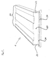
- FIG. 1 shows a start-up track 1 for ski jumps, which consists only of a cooling starting track 20.
- Bottom 24 and side walls 22 of the cooling run-track 20 form a box-shaped profile.
- Snow 60, natural snow or artificial snow or a mixture of both, can be introduced into the cooling starting track 20.
- the distance of the side walls 22 is chosen so that in the filled snow two ruts can be formed in the space required for ski jumping. On the other hand, the distance of the side walls 22 should not go well beyond the extent required to keep the cooling snow amount as low as possible. Ideally, a distance of about 50 cm appears for the side walls 22.
- the cooling device 26 is provided, which can be realized for example by a flowed through by a coolant pipe plant.
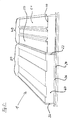
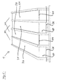
- FIG. 2 shows a run-in track 1 consisting of a cooling inrun track 20 and a directly adjacent arranged Alternativanlaufspur 40.
- the cooling inrun track 20 corresponds to the in FIG. 1 shown.
- the alternative ruts 50 and 51 of the alternative start-up track 40 have a sliding surface so that the alternative start-up track can be operated without snow.
- the width and spacing of the alternative starting ruts are selected according to the requirements of ski jumping.
- a track interior width of about 13.5 cm and a distance between the center lines of the track grooves of 32 cm is selected.
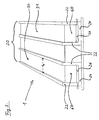
- FIG. 3 shows a run-up track 1, which consists of a cooling run-track 20, wherein the cooling run-up track 20 is formed of two parallel adjacent cooling grooves 30 and 31.
- the two cooling grooves 30 and 31 are in turn formed from the walls 22 and the bottom 24.
- the distance b of the walls 22 of a cooling raceway 30 or 31 is selected so that the cooling raceway can accommodate a jump skis so that laterally for the purposes of ski jumping sufficient play remains.
- Particularly favorable is a width b of 13 to 14 cm.
- the cooling grooves 30 and 31 are filled with natural and / or artificial snow 60. Since only the preferably 13 to 14 cm wide cooling grooves 30 and 31, but not the gap between the two cooling grooves with snow 60 must be filled, the need for snow 60 is comparatively low. In the FIG. 3 Thus, cooling intake track 20 shown permits minimizing the amount of snow required for two skipping boats, since only the two cooling ramp grooves 30 and 31 provided for each skip must be filled with snow. On the bottom 24 of the cooling grooves 30 and 31 is the cooling device 26, which ensures that the snow in the cooling grooves 30 and 31 60 is maintained even with changing outside temperatures.
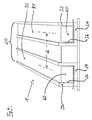
- FIG. 4 shows a run-in track 1, which consists of a cooling start track 20 similar to the in FIG. 3 shown consists.
- the cooling device 26 is mounted not only on the floor 24, but on the floor 24 and on the side walls 22.
- the cooling grooves 30 and 31 preferably have a depth of 25 cm and a width b of 13 cm and a mutual distance d of 32 cm.
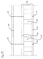
- FIG. 10 shows a start-up track representing a combination of a cooling start track 20 and an alternate start track 40.
- Cooling inrun track 20 and alternative inrun track 40 are arranged offset in one another, that is, in the horizontal direction, cooling grooves 30 and 31 alternate with alternative ruts 50 and 51.
- FIG. 5 there is a cooling lane 30 on the left, an alternative lane 50 on the right, a cooling lane 31 on the right next to it, and an alternative lane 51 on the far right.
- the staggered arrangement of cooling track 20 and Altemativanlaufspur 40 allows to accommodate the two starting tracks on minimum width.
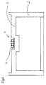
- FIG. 6 shows a SchanzenbauMechharm 2 with a Schanzendeckplatte 3 in which a run-up channel 4 is inserted.
- the trained as a module inrun track 1 can be sunk.
- the snow surface in the cooling grooves 30 and 31 and the bottom 44 of the alternative ruts 50 and 51 at the same height as the surface of the Schanzendeckplatte 3.
- the characteristic for the ski jump start parabola for the inrun track 1 is the same as that for the surface of the Schanzendeckplatte 3.
- the starting parabola is not changed by the use of the inrun 1 against the normal ski surface.
- FIG. 7 shows a run-in track 1 with mutually offset cooling and Alternativanlaufspur in cross section.
- the bottoms 44 of the alternative ruts 50 and 51 are underlaid with dynamometric plates 46.
- the Dynamometrieplatten 46 the force pulses developed by the ski jumpers can be measured, and separately for each talus. The measurement can be carried out, for example, by piezoelectric elements integrated into the dynamometric plates 46. Accurate measurement requires mechanical decoupling of the bottoms 44 of the alternative track grooves 50 and 51 and the dynamometry plates 46 from the lateral enclosure of the alternative track grooves 50 and 51.
- This mechanical decoupling may be achieved, for example, by a narrow gap 48 between the dynamometric plate 46 and the walls 22 and 42 , The gap is preferably 2.5 mm wide.
- the complete mechanical decoupling of the dynamometric plates also requires a mechanical decoupling 47 of coolant lines optionally passing through the dynamometric plate.
- the decoupling 47 can be achieved for example by flexible coolant lines.
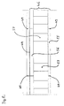
- FIG. 8 shows a longitudinal section through an alternative ruts 50 or 51, wherein the bottom 44 of the alternative ruts 50 is backed by dynamometry plates 46.
- FIG. 8 shows in the middle a complete Dynamometrieplatte 46 and right and left adjacent Dynamometrieplatten 46 each half.
- the dynamometry plates 46 consist of a bottom plate 55, a cover plate 56, and force sensors 57 mounted therebetween.
- the force sensors may include, for example, piezoelectric elements.
- the bottom plate 55 is fixed on the ski surface or on the module carrier.
- the cover plate is non-positively connected to the bottom of the alternative rut.
- the dynamometric plates are mechanically decoupled in the start-up direction at regular intervals.
- the mechanical decoupling can be achieved by a narrow gap 49 between two successive Dynamometrieplatten 46. Preferably, the gap is a few millimeters wide.
- the mechanical decoupling in the start-up direction allows an analysis of the bounce developed by the Springer, which is resolved by time and place.
- FIG. 9 shows a mutually offset cooling and Alternativanlaufspur 20, 40.
- the left cooling groove 30 and the left alternative furrow 50 are underlaid by a common Dynamometrieplatte 46.
- the right cooling groove 31 and the right alternative groove 51 have a common dynamometric plate 46.
- the mechanical decoupling occurs between the middle tracks 50 and 31 through the gap 48.
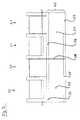
- FIG. 10 shows a longitudinal section along an alternative trough 50 or 51 in a run-in track according to FIG. 9 , Due to the required depth of the cooling grooves 30 and 31, the overall structure is correspondingly higher. Also in this construction, the dynamometric plates 46 are mechanically decoupled in the longitudinal direction through narrow gaps 49.
- the above-described invention achieves a number of advantages.
- a run-in track of snow or ice is provided, which is far less dependent on the weather conditions than previously known tarnishing tracks.
- the combination with the Altemativanlaufspur makes the inrun track even without snow and therefore usable all year round.
- the inrun track according to the invention can also be integrated into existing ski jumping facilities, especially when the inrun track according to the invention is designed as a module.
- the connection with the dynamometric plates allows a particularly accurate analysis of the force impulses developed by the ski jumper.
- the inrun track according to the invention is particularly well suited for training purposes.
Landscapes
- Engineering & Computer Science (AREA)
- Architecture (AREA)
- Civil Engineering (AREA)
- Structural Engineering (AREA)
- Thermal Sciences (AREA)
- Mechanical Engineering (AREA)
- Physics & Mathematics (AREA)
- General Engineering & Computer Science (AREA)
- Turbine Rotor Nozzle Sealing (AREA)
- Glass Compositions (AREA)
- Wind Motors (AREA)
- Road Paving Structures (AREA)
- Compositions Of Macromolecular Compounds (AREA)
- Transition And Organic Metals Composition Catalysts For Addition Polymerization (AREA)
Description
- Die Erfindung betrifft eine Anlaufspur für Skisprungschanzen. Solche Anlaufspuren sehen regelmäßig ein Paar von Spurrinnen vor, so daß für jeden Sprungski des Skispringers eine Spurrinne vorhanden ist.
- Vorbekannt sind Anlaufspuren, bei denen die beiden Spurrinnen in eine durchgängige, auf der Schanzenoberfläche befindliche Schnee- bzw. Eisdecke eingeformt sind. Weiterhin ist aus dem deutschen Gebrauchsmuster
200 11 567 eine Anlaufspur bekannt, bei der der Boden der Spurrinnen aus metallischen Gleitspurschindeln gebildet ist. Die Oberflächengestaltung und -beschichtung der Gleitspurschindeln erlaubt es, daß die Skispringer ähnlich wie auf Schnee die Anlaufspur hinabgleiten. - Bekannt ist ferner aus der
DE 198 43 901 C2 ein Verfahren zur Haltbarmachung von Schnee und eine Kühlmatteneinrichtung zur Durchführung dieses Verfahrens. Verfahren und Vorrichtung dienen der Haltbarmachung von Schnee auf Berghängen und Skipisten. DieDE 196 38 714 A1 offenbart einen mattenartigen Wärmetauscher für Kühl- und/oder Heizzwecke. Aus derCH 174 772 CH 174 551 - Die vorbekannten Anlaufspuren für Skisprungschanzen haben den Nachteil, daß sie nur eingeschränkt nutzbar sind. Die in die geschlossene Schneedecke eingeformte Anlaufspur setzt zunächst voraus, daß ausreichende Schneemengen vorhanden sind. Ist die Schanze aufgrund ungünstiger Witterungsverhältnisse nicht mit ausreichend Naturschnee bedeckt, muß mit teilweise erheblichem Aufwand Naturschnee und/oder Kunstschnee herangeschafft und auf die Schanze aufgebracht werden. Bei ungünstigen, insbesondere wechselnden Witterungsverhältnissen ist die Schneedecke auf der Sprungschanze zudem nur sehr begrenzt haltbar. Auch in den Wintermonaten steigen die Temperaturen in der Umgebung der meist in den Tälern gelegenen Sprungschanzen teilweise deutlich und für längere Dauer über den Gefrierpunkt. Dauerhaft konstante Schnee- bzw. Eisbedingungen können daher auf den vorbekannten Sprungschanzen selbst über die Wintermonate regelmäßig nicht bereitgestellt werden.
- Die aus dem deutschen Gebrauchsmuster 200 11 567 bekannte schneelose Anlaufspur kann für offizielle Wettkämpfe nicht genutzt werden, da die Wettkampfbedingungen einen Anlauf auf Schnee oder Eis erfordern. Die schneelose Anlaufspur kann daher nur für Trainingszwecke eingesetzt werden.
- Aus der Offenlegungsschrift
DE 3003069 A1 ist ein Skispurelement bekannt, welches Abkühlrohre zur Abkühlung der Skispur umfaßt. - Ausgehend vom vorbekannten Stand der Technik ist es daher Aufgabe der vorliegenden Erfindung, eine verbesserte Anlaufspur für Skisprungschanzen vorzuschlagen. Insbesondere soll die erfindungsgemäße Anlaufspur über einen längeren Zeitraum authentische und möglichst gleichbleibende Anlaufbedingungen auf Schnee oder Eis gewährleisten. Vor allen Dingen soll der Einfluß der Witterung auf die Schnee- bzw. Eisverhältnisse in der Anlaufspur eingeschränkt werden. Weiterhin soll die erfindungsgemäße Anlaufspur einfach und kostengünstig hergestellt und betrieben werden können.
- Erfindungsgemäß wird die Aufgabe durch eine Anlaufspur mit den Merkmalen des Patentanspruchs 1 gelöst. Die erfindungsgemäße Anlaufspur umfaßt eine Kühlanlaufspur mit mindestens zwei im wesentlichen senkrechten Seitenwänden. Nach unten ist die Kühlanlaufspur beispielsweise durch einen horizontal verlaufenden Boden abgeschlossen, nach oben ist sie offen. Die Kühlanlaufspur kann aufgrund ihres kasten- bzw. wannenförmigen Profils mit Schnee, und zwar mit Naturschnee oder mit Kunstschnee oder mit einer Mischung von beidem, gefüllt werden. Weiterhin ist erfindungsgemäß eine Kühleinrichtung vorgesehen, mit der die Kühlanlaufspur zur Erhaltung des in ihr befindlichen Schnees gekühlt werden kann. Die Kühleinrichtung kann beispielsweise durch ein von einem Kühlmittel durchströmtes Rohrwerk realisiert werden.
- Zusätzlich zu der Kühlanlaufspur ist eine Alternativanlaufspur vorgesehen, die ohne Schnee- bzw. Eisauflage nutzbar ist. Erreicht wird dies dadurch, daß die Anlaufspur eine Gleitoberfläche aufweist. Die Gleitoberfläche kann eine Noppenstruktur aufweisen. Das Gleitmaterial kann aus Metall und/oder Keramik und/oder Glas und/oder anderen geeigneten Werkstoffen bestehen.
- Vorzugsweise wird die Höhe der Seitenwände, d.h. die Tiefe der Kühlanlaufspur so gewählt, daß eine Schneehöhe bis 25 cm in der Kühlanlaufspur erreicht werden kann. Um einem Abrutschen des Schnees in der Kühlanlaufspur entgegenzuwirken, ist es günstig, am Boden der Kühlanlaufspur Querstege in der Höhe von einigen Zentimetern anzubringen, die den Schnee halten. Die Querstege können gleichzeitig Bestandteil der Kühleinrichtung sein. Die Breite der Kühlanlaufspur sollte so gewählt werden, daß sie die für zwei Spurrinnen erforderliche Breite nicht wesentlich übersteigt. Dafür wird regelmäßig eine Breite von ca. 45 cm ausreichen. Die Kühlanlaufspur kann zusätzlich isoliert werden, um den Kühlaufwand zu reduzieren.
- Mit der Erfindung werden die erwünschten Vorteile erreicht. Durch die Kühlung können die Schnee- bzw. Eisverhältnisse in der Kühlanlaufspur auch bei wechselnden Witterungsverhältnissen über eine vergleichsweise lange Dauer kostant gehalten werden. Da nur die vorzugsweise ca. 45 cm breite Kühlanlaufspur gekühlt werden muß, ist die zu kühlende Schnee- bzw. Eismenge und damit auch der Kühlauf wand vergleichsweise gering. Damit lassen sich die konstanten Bedingungen vergleichsweise kostengünstig herstellen. Die Erfindung gewährt auf diese Weise Unabhängigkeit von Witterungseinflüssen und damit die von Wettkampfveranstaltern erwünschte hohe Veranstaltungssicherheit.
- Durch die Gleitoberfläche wird ermöglicht, daß die Skispringer in der Alternativanlaufspur ohne Schneeauflage aber ähnlich wie auf Schnee die Anlaufspur hinabgleiten können. Die Kombination einer Kühlanlaufspur mit einer Alternativanlaufspur erlaubt eine multifunktionelle Nutzung bei verschiedensten Witterungsverhältnissen und in den verschiedenen Jahreszeiten. In der Wintersaison (November bis März) kann aufgrund der niedrigeren Durchschnittstemperaturen der Schnee bzw. das Eis in der Kühlanlaufspur so erhalten werden, daß die Kühlanlaufspur auch bei Wetterschwankungen durchgehend genutzt werden kann. In der warmen Sommersaison kann die Alternativspur zu Trainingszwecken genutzt werden. Damit kann die gleiche Schanze ganzjährig zum Skispringen genutzt werden. Insbesondere ist ohne bauliche Veränderungen ein Wechsel vom Winter- zum Sommerbetrieb möglich.
- In einer weiter vorteilhaften Ausgestaltung wird die Kühlanlaufspur aus einem Paar von parallel nebeneinander verlaufenden Kühlspurrinnen gebildet. Jede der beiden Kühlspurrinnen hat zwei Seitenwände, die zusammen mit dem dazwischenliegenden Boden den nach oben geöffneten Kühlspurrinnen einen insgesamt im wesentlichen U-förmigen Querschnitt verleihen. Aufgrund ihres Kastenprofils können die Kühlspurrinnen mit Schnee, und zwar mit Naturschnee oder mit Kunstschnee oder mit einer Mischung aus beidem, gefüllt werden. Bei dieser Ausgestaltung reicht es aus, nur die Kühlspurrinnen zu kühlen, wodurch die zu kühlende Schnee- bzw. Eismenge weiter reduziert wird.
- In einer bevorzugten Ausgestaltung erfolgt die Kühlung am Boden der Kühlspurrinnen, insbesondere dadurch, daß der Boden der Kühlspurrinnen als Kühlboden ausgestaltet ist, der von einem Kühlmittel durchströmt wird. In einer anderen Ausgestaltung erfolgt die Kühlung an den Seitenwänden der Kühlspurrinnen, wobei die Wände als Kühlwände ausgestaltet sein können, die von einem Kühlmittel durchströmt werden. Ebenso kann die Kühlung sowohl am Boden als auch an den Wänden der Kühlspurrinnen erfolgen, insbesondere dadurch, daß ein Kühlboden und Kühlwände vorgesehen sind, die von einem Kühlmittel durchströmt werden. Durch die Kühlung nur am Boden können die Kühlkosten gesenkt werden. Durch eine Kühlung am Boden und an den Seitenwänden kann die Schneemetamorphose von Schnee zu Eis verzögert werden, so daß die Schneebedingungen über eine längere Dauer konstant bleiben.
- Vorteilhafterweise wird die Breite der Kühlspurrinnen so gewählt, daß sie die Breite eines Sprungskis etwas übersteigt. Dadurch kann der Sprungski einerseits mit seitlichem Spiel in der Kühlspurrinne aufgenommen werden, andererseits wird durch die Begrenzung der Breite der Kühlspurrinnen die erforderliche Schneemenge reduziert. Besonders geeignet ist eine Breite der Kühlspurrinnen von 13,5 cm. Vorteilhafterweise wird der Abstand zwischen den Mittelachsen der Kühlspurrinnen so gewählt, daß er ungefähr dem Abstand der Sprungskier beim Anlauf auf der Schanze entspricht. Am geeignetsten ist der bei Skisprungwettbewerben übliche Abstand von 32 cm.
- Mit der vorbeschriebenen besonderen Ausgestaltung werden die erfindungsgemäßen Vorteile verstärkt. Die für das Skispringen erforderliche Schneeunterlage wird auf die erforderliche Mindestbreite, nämlich auf die Breite zweier Sprungskier zuzüglich etwas seitlichem Spiel reduziert. Dadurch wird die erforderliche Schneemenge reduziert und der Kühlaufwand minimiert.
- In einer weiter bevorzugten Ausgestaltung besteht die Alternativanlaufspur aus einem Paar von parallel nebeneinander verlaufenden Alternativspurrinnen, deren Böden als Gleitoberfläche ausgestaltet sind.
- Besonders vorteilhaft ist es, wenn Schneeoberfläche in der Kühlanlaufspur und der Boden der Alternativanlaufspur auf gleicher Höhe sind, da sich dann die Anlaufparabel für die Skispringer beim Wechsel von der Kühlanlaufspur zur Alternativanlaufspur nicht ändert. Die Anlaufparabel bestimmt die geometrische Charakteristik des Anlaufs. Für eine unveränderte Anlaufparabel sollten daher Kühlanlaufspur und Alternativanlaufspur relativ zueinander so angeordnet sein, daß die Schneeoberfläche in der Kühlanlaufspur in gefülltern Zustand auf gleicher Höhe ist wie der Boden der Alternativanlaufspur.
- Besonders vorteilhaft ist es, wenn Kühlanlaufspur und Alternativanlaufspur ineinander versetzt angeordnet sind, d.h. wenn die beiden Typen von Spurrinnen, also Kühlspurrinnen und Alternativspurrinnen, abwechselnd angeordnet sind, so daß im Zwischenraum zwischen den beiden Kühlspurrinnen eine Alternativspurrinne zu liegen kommt und im Zwischenraum zwischen den beiden Alternativspurrinnen eine Kühlspurrinne. Dadurch kann die Gesamtbreite der Anlaufspur gering gehalten werden, so daß die zusätzliche Anlaufspur nur zur Verbreiterung um die Breite einer Spurrinne führt. Dadurch wird es teilweise möglich, die vorteilhafte Kombination von Kühlanlaufspur und Alternativanlaufspur auf bestehenden Schanzenanlagen ohne große Umbaumaßnahmen zu installieren.
- Vorteilhafterweise ist die aus Kühlanlaufspur und Alternativanlaufspur bestehende Anlaufspur als Modul ausgestaltet, das in die Oberfläche der Schanzendeckplatte eingelassen werden kann. Wird die Anlaufspur so weit versenkt, daß ihre Oberkante bündig mit der Oberfläche der Schanzendeckplatte abschließt, so kann man die Anlaufspur mit einer Abdeckung abdecken und erhält eine ebene Schanzenoberfläche. Diese ebene Oberfläche kann mit Schnee bedeckt werden, so daß die Schanze auch auf herkömmliche Art und Weise genutzt werden kann, das heißt durch vollständige Abdeckung der Schanzenoberfläche mit Natur- und/oder Kunstschnee und Einformung der Anlaufspur in die geschlossene Schneedecke. Auf diese Weise erlaubt die erfindungsgemäße Anlaufspur eine multifunktionelle Nutzung der Schanzenanlage.
- In einer weiter vorteilhaften Ausgestaltung der Erfindung sind im Absprungbereich der Anlaufspur, vorzugsweise auf den letzten elf Metern vor dem Absprung, Dynamometrieplatten unter den Böden der Alternativspurrinnen angebracht. Die Dynamometrieplatten dienen der Messung der vom Skispringer entwickelten Sprungkraft. Dadurch, daß sich die Dynamometrieplatten unter jeder der beiden Alternativspurrinnen befinden, kann die von jedem Bein entwickelte Sprungkraft getrennt ermittelt werden.
- Um möglichst gute Meßergebnisse für diese Kraftmessung zu erzielen, ist es vorteilhaft, die Böden der Alternativspurrinnen und die darunter befindlichen Dynamometrieplatten von der seitlichen Einfassung der Alternativspurrinnen mechanisch zu entkoppeln. Dies kann dadurch erreicht werden, daß der Boden der Alternativspurrinnen und die Dynamometrieplatten nicht mit der Seitenwand der Alternativspur verbunden werden, sondern sich in vertikaler Richtung zwischen den Wänden der Alternativspurrinnen frei bewegen können.
- Dies kann vorteilhafterweise durch eine entsprechende Ausgestaltung der Dynamometrieplatten erreicht werden. Diese bevorzugten Dynamometrieplatten bestehen aus einer Bodenplatte und einer Deckplatte, zwischen denen sich die Kraftsensoren, z.B. piezoelektrische Elemente, befinden. Die Bodenplatte wird mit dem Schanzenbaukörper bzw. mit dem Einbaumodul fest verbunden. Auf diese Bodenplatte sind die Kraftsensoren befestigt, die wiederum mit der Deckplatte fest verbunden sind. Besonders günstig ist es, wenn Bodenplatte und Deckplatte weitgehend die Breite der Alternativspurrinne einnehmen, so daß lediglich ein schmaler Spalt zu der seitlichen Einfassung der Alternativspurrinnen verbleibt. Auf den Deckplatten der Dynamometrieplatten wird dann der Boden der Alternativspurrinnen befestigt. Damit ist der Boden der Alternativspurrinnen nur von den Dynamometrieplatten getragen und kann sich frei zwischen der seitlichen Einfassung der Alternativspurrinnen auf und ab bewegen.
- Soweit Teile der Kühleinrichtung, insbesondere Kühlleitungen durch die Dynamometrieplatten geführt werden, kann auch für diese eine mechanische Entkopplung vorgesehen werden.
- Bei versetzt angeordneter Kühl- und Alternativanlaufspur, also wenn sich zwischen den Spurrinnen der Kühlanlaufspur eine Alternativspurrinne und zwischen den Spurrinnen der Alternativanlaufspur eine Kühlspurrinne befindet, können die für das gleiche Sprungbein vorgesehenen Kühl- und Alternativspurrinnen auch mit einer gemeinsamen Dynamometrieplatte unterlegt werden. Dies wird erreicht durch Dynamometrieplatten, die einer äußeren und der jeweils benachbarten inneren Spurrinne gemeinsam zugeordnet sind. Die mechanische Entkopplung muß dann in der Mitte der vier Spurrinnen also zwischen den beiden innenliegenden Spurrinnen erfolgen. Die Entkopplung kann beispielsweise durch einen Spalt erfolgen. Da die beiden rechten und die beiden linken Spurrinnen dem gleichen Sprungbein zugeordnet sind, kann auch mit dieser Ausgestaltung der Dynamometrieplatten die von jedem Bein des Skispringers entwickelte Sprungkraft getrennt ermittelt werden.
- In einer weiter vorteilhaften Ausgestaltung werden die Dynamometriepatten in Anlaufrichtung in regelmäßige Abständen, vorzugsweise im Abstand von einem Meter mechanisch entkoppelt. Dies erlaubt es, die Kraftentwicklung des Skispringers in der Absprungphase zeitlich und örtlich aufzuschlüsseln. Auch diese Entkopplung kann durch einen Spalt zwischen aufeinanderfolgenden Dynamometrieplatten erreicht werden.
- Ausführungsbeispiele der Erfindung werden anhand der nachstehenden Figuren im Einzelnen erläutert. Dabei zeigt:
- Fig. 1:
- eine konventionelle Anlaufspur, bestehend aus einer mit Schnee gefüllten Kühlanlaufspur, bei der die Spurrinnen in den eingefüllten Schnee eingeformt sind,
- Fig. 2:
- eine Anlaufspur bestehend aus einer Kühlanlaufspur und ei- ner daneben angebrachten Alternativanlauspur,
- Fig. 3:
- eine aus einem Paar von Kühlspurrinnen gebildete Kühlan- laufspur, wobei sich die Kühleinrichtung am Boden der Kühl- spurrinnen befindet,
- Fig. 4:
- eine aus einem Paar von Kühlspurrinnen gebildete Kühlan- laufspur, wobei sich die Kühleinrichtung am Boden und an den Wänden der Kühlspurrinnen befindet,
- Fig. 5:
- eine aus einer Kühlanlaufspur und einer Alternativanlaufspur bestehende Anlaufspur, wobei die Kühlspurrinnen und die Al- temativspurrinnen ineinander versetzt angeordnet sind,
- Fig. 6:
- einen Schanzenbaukörper mit einem Anlauf-Kanal in der Schanzendeckplatte, in den das Anlaufspurmodul eingelassen ist,
- Fig. 7:
- Querschnitt durch ineinander versetzt angeordnete Kühlan- laufspur und Alternativanlaufspur, wobei die Alternativanlauf- spur mit Dynamometrieplatten unterlegt ist,
- Fig. 8:
- Längsschnitt durch eine Alternativspurrinne, die mit Dynamo- metrieplatten unterlegt ist,
- Fig. 9:
- Querschnitt durch ineinander versetzt angeordnete Kühlan- laufspur und Alternativanlaufspur, wobei die beiden linken und die beiden rechten Spurrinnen von jeweils einer gemeinsamen Dynamometrieplatte unterlegt sind,
- Fig. 10:
- Längsschnitt durch eine Alternativanlaufspur in einer Anlauf- spur entsprechend
Figur 9 . -
Figur 1 zeigt eine Anlaufspur 1 für Skisprungschanzen, die nur aus einer Kühlanlaufspur 20 besteht. Boden 24 und Seitenwände 22 der Kühlanlaufspur 20 bilden ein kastenförmiges Profil. In die Kühlanlaufspur 20 kann Schnee 60, und zwar Naturschnee oder Kunstschnee oder eine Mischung aus beidem, eingefüllt werden. - Der Abstand der Seitenwände 22 ist so gewählt, daß in den eingefüllten Schnee zwei Spurrinnen im für das Skispringen erforderlichen Abstand eingeformt werden können. Andererseits sollte der Abstand der Seitenwände 22 nicht deutlich über das erfordliche Maß hinausgehen, um die kühlende Schneemenge möglichst gering zu halten. Ideal erscheint für die Seitenwände 22 ein Abstand von etwa 50 cm. Am Boden der Kühlanlaufspur ist die Kühleinrichtung 26 vorgesehen, die beispielsweise durch ein von einem Kühlmittel durchströmtes Rohrwerk realisiert werden kann.
-
Figur 2 zeigt eine Anlaufspur 1 bestehend aus einer Kühlanlaufspur 20 und einer direkt daneben angeordneten Alternativanlaufspur 40. Die Kühlanlaufspur 20 entspricht der inFigur 1 gezeigten. Die Alternativspurrinnen 50 und 51 der Alternativanlaufspur 40 weisen eine Gleitoberfläche auf, so daß die Alternativanlaufspur schneelos betrieben werden kann. Breite und Abstand der Alternativanlaufspurrinnen werden entsprechend den Erfordernissen des Skispringens gewählt. Bevorzugt wird eine Spurrinnenbreite von etwa 13,5 cm und ein Abstand zwischen den Mittellinien der Spurrinnen von 32 cm gewählt. -
Figur 3 zeigt eine Anlaufspur 1, die aus einer Kühlanlaufspur 20 besteht, wobei die Kühlanlaufspur 20 aus zwei parallel nebeneinander verlaufenden Kühlspurrinnen 30 und 31 gebildet ist. Die beiden Kühlspurrinnen 30 und 31 werden ihrerseits aus den Wänden 22 und dem Boden 24 gebildet. Der Abstand b der Wände 22 einer Kühlspurrinne 30 oder 31 wird so gewählt, daß die Kühlspurrinne einen Sprungski so aufnehmen kann, daß seitlich für die Zwecke des Skispringens ausreichend Spiel verbleibt. Besonders günstig ist eine Breite b von 13 bis 14 cm. - Die Kühlspurrinnen 30 und 31 werden mit Natur- und/oder Kunstschnee 60 gefüllt. Da nur die vorzugsweise 13 bis 14 cm breiten Kühlspurrinnen 30 und 31, nicht aber der Zwischenraum zwischen den beiden Kühlspurrinnen mit Schnee 60 gefüllt werden muß, ist der Bedarf an Schnee 60 vergleichsweise gering. Die in
Figur 3 gezeigte Kühlanlaufspur 20 erlaubt also eine Minimierung der für zwei Sprungskier erforderlichen Schneemenge, da nur die beiden, für jeweils einen Sprungski vorgesehenen Kühlanlaufspurrinnen 30 und 31, mit Schnee gefüllt werden müssen. Auf dem Boden 24 der Kühlspurrinnen 30 und 31 befindet sich die Kühleinrichtung 26, die dafür sorgt, daß der in den Kühlspurrinnen 30 und 31 befindliche Schnee 60 auch bei wechselnden Außentemperaturen erhalten bleibt. -
Figur 4 zeigt eine Anlaufspur 1, die aus einer Kühlanlaufspur 20 ähnlich der inFigur 3 gezeigten besteht. Im Unterschied zuFigur 3 ist in den Kühlspurrinnen 30 und 31 inFigur 4 die Kühleinrichtung 26 nicht nur am Boden 24, sondern am Boden 24 und an den Seitenwänden 22 angebracht. Dadurch wird eine noch bessere Kühlung des in den Kühlspurrinnen 30 und 31 befindlichen Schnees 60 erreicht. Auf diese Weise kann die Schneemetamorphose von Schnee zu Eis verzögert werden. Die Kühlspurrinnen 30 und 31 haben vorzugsweise eine Tiefe von 25 cm und eine Breite b von 13 cm sowie einen gegenseitigen Abstand d von 32 cm. -
Figur 5 zeigt eine Anlaufspur, die eine Kombination einer Kühlanlaufspur 20 und einer Alternativanlaufspur 40 darstellt. Kühlanlaufspur 20 und Alternativanlaufspur 40 sind ineinander versetzt angeordnet, das heißt in horizontaler Richtung wechseln sich Kühlspurrinnen 30 und 31 und Alternativspurrinnen 50 und 51 ab. InFigur 5 befindet sich links eine Kühlspurrinne 30, rechts daneben eine Alternativspurrinne 50, rechts daneben folgt eine Kühlspurrinne 31 und ganz rechts befindet sich wieder eine Alternativspurrinne 51. Natürlich ist auch die umgekehrte Abfolge möglich.
Die ineinander versetzte Anordnung von Kühlanlaufspur 20 und Altemativanlaufspur 40 erlaubt es, die beiden Anlaufspuren auf minimaler Breite unterzubringen. -
Figur 6 zeigt einen Schanzenbaukörper 2 mit einer Schanzendeckplatte 3 in die ein Anlaufkanal 4 eingelassen ist. In dem Anlaufkanal 4 kann die als Modul ausgebildete Anlaufspur 1 versenkt werden. So kann erreicht werden, daß die Schneeoberfläche in den Kühlspurrinnen 30 und 31 bzw. der Boden 44 der Alternativspurrinnen 50 und 51 auf gleicher Höhe ist wie die Oberfläche der Schanzendeckplatte 3. Dies hat zur Folge, daß die für die Sprungschanze charakteristische Anlaufparabel für die Anlaufspur 1 die gleiche ist wie die für die Oberfläche des Schanzendeckplatte 3. Dadurch wird die Anlaufparabel durch die Verwendung der Anlaufspur 1 gegenüber der normalen Schanzenoberfläche nicht verändert. -
Figur 7 zeigt eine Anlaufspur 1 mit ineinander versetzt angeordneter Kühl- und Alternativanlaufspur im Querschnitt. Dabei sind die Böden 44 der Alternativspurrinnen 50 und 51 mit Dynamometrieplatten 46 unterlegt. Mit den Dynamometrieplatten 46 können die von den Skispringern entwickelten Kraftimpulse gemessen werden, und zwar getrennt für jedes Sprungbein. Die Messung kann beispielsweise durch in die Dynamometrieplatten 46 integrierte piezoelektrische Elemente erfolgen. Eine genaue Messung erfordert eine mechanische Entkopplung der Böden 44 der Alternativspurrinnen 50 und 51 sowie der Dynamometrieplatten 46 von der seitlichen Einfassung der Alternativspurrinnen 50 und 51. Diese mechanische Entkopplung kann beispielsweise durch einen schmalen Spalt 48 zwischen Dynamometrieplatte 46 und den Wänden 22 und 42 erreicht werden. Der Spalt ist vorzugsweise 2,5 mm breit. Die vollständige mechanische Entkopplung der Dynamometrieplatten erfordert auch eine mechanische Entkopplung 47 von durch die Dynamometrieplatte gegebenenfalls hindurchführenden Kühlmittelleitungen. Die Entkopplung 47 kann beispielsweise durch flexible Kühlmittelleitungen erreicht werden. -
Figur 8 zeigt einen Längsschnitt durch eine Alternativspurrinne 50 oder 51, wobei der Boden 44 der Alternativspurrinne 50 von Dynamometrieplatten 46 unterlegt ist.
Figur 8 zeigt in der Mitte eine vollständige Dynamometrieplatte 46 und rechts und links benachbarte Dynamometrieplatten 46 jeweils zur Hälfte. Die Dynamometrieplatten 46 bestehen aus einer Bodenplatte 55, einer Deckplatte 56 und dazwischen angebrachten Kraftsensoren 57. Die Kraftsensoren können beispielsweise piezoelektrische Elemente enthalten. Die Bodenplatte 55 wird auf der Schanzenoberfläche oder am Modulträger befestigt. Die Deckplatte wird kraftschlüssig mit dem Boden der Alternativspurrinne verbunden. Die Dynamometrieplatten werden in Anlaufrichtung in regelmäßigen Abständen mechanisch entkoppelt. Die mechanische Entkopplung kann durch einen schmalen Spalt 49 zwischen zwei aufeinander folgenden Dynamometrieplatten 46 erreicht werden. Vorzugsweise ist der Spalt einige Millimeter breit. Die mechanische Entkopplung in Anlaufrichtung erlaubt eine nach Zeit und Ort aufgelöste Analyse der vom Springer entwickelten Sprungkraft. -
Figur 9 zeigt eine ineinander versetzt angeordnete Kühl- und Alternativanlaufspur 20, 40. Die linke Kühlspurrinne 30 und die linke Alternativspurrinne 50 sind von einer gemeinsamen Dynamometrieplatte 46 unterlegt. Ebenso haben die rechte Kühlspurrinne 31 und die rechte Alternativspurrinne 51 eine gemeinsame Dynamometrieplatte 46. Die mechanische Entkopplung erfolgt zwischen den mittleren Spurrinnen 50 und 31 durch den Spalt 48. Mit dieser Anordnung können die vom Skispringer entwickelten Kraftimpulse getrennt für jedes Sprungbein gemessen werden, unabhängig davon, ob die Kühlanlaufspur 20 oder die Alternativanlaufspur 40 benutzt wird. -
Figur 10 zeigt einen Längsschnitt entlang einer Alternativspurrinne 50 oder 51 in einer Anlaufspur gemäßFigur 9 . Durch die erforderliche Tiefe der Kühlspurrinnen 30 und 31 wird der Gesamtaufbau entsprechend höher. Auch bei dieser Konstruktion werden die Dynamometrieplatten 46 in Längsrichtung durch schmale Spalte 49 mechanisch entkoppelt. - Durch die vorbeschriebene Erfindung werden eine Reihe von Vorteilen erreicht. Auf einfach und kostengünstige Weise wird eine Anlaufspur aus Schnee oder Eis zur Verfügung gestellt, die von Witterungseinflüssen weit weniger abhängig ist als vorbekannte Anlaufspuren. Dadurch wird für die Veranstalter ein wesentlich höheres Maß an Veranstaltungssicherheit erreicht. Die Kombination mit der Altemativanlaufspur macht die Anlaufspur auch ohne Schnee und damit ganzjährig nutzbar. Aufgrund des geringen Raumbedarfs, insbesondere der geringen erforderlichen Breite kann die erfindungsgemäße Anlaufspur auch in bestehende Schanzenanlagen integriert werden, insbesondere wenn die erfindungsgemäße Anlaufspur als Modul ausgestaltet ist. Die Verbindung mit den Dynamometrieplatten erlaubt eine besonders genaue Analyse der vom Skispringer entwickelten Kraftimpulse. Damit ist die erfindungsgemäße Anlaufspur insbesondere für Trainingszwecke sehr gut geeignet.
Claims (13)
- Anlaufspur (1) für Skisprungschanzen, wobei die Anlaufspur (1) mindestens eine Kühlanlaufspur (20) umfasst, wobei die Kühlanlaufspur mindestens zwei Wände (22) und mindestens einen Boden (24) aufweist, wobei in die Kühlanlaufspur (20) Schnee (60), insbesondere Kunstschnee oder eine Mischung aus Kunst- und Naturschnee, einbringbar ist, und wobei eine Kühleinrichtung (26) zur Kühlung der Kühlanlaufspur (20) vorgesehen ist, dadurch gekennzeichnet, dass zusätzlich zu der mindestens einen Kühlanlaufspur (20) eine Alternativanlaufspur (40) vorgesehen ist, wobei die Alternativanlaufspur (40) eine Gleitoberfläche, insbesondere Gleitnoppen, aus Metall und/oder Keramik und/oder Glas und/oder anderen Werkstoffen aufweist, so dass die Alternativanlaufspur (40) ohne Schneeauflage nutzbar ist.
- Anlaufspur (1) für Skisprungschanzen nach Anspruch 1, dadurch gekennzeichnet, dass die mindestens eine Kühlanlaufspur (20) ein Paar von parallel nebeneinander verlaufenden Kühlspurrinnen (30, 31) umfaßt, wobei die Kühlspurrinnen (30, 31) einen im wesentlichen U-förmigen Querschnitt aufweisen, wobei der Schnee (60) in die Kühlspurrinnen (30, 31) einbringbar ist, und wobei die Kühlspurrinnen (30, 31) durch die Kühleinrichtung (26) kühlbar sind.
- Anlaufspur (1) für Skisprungschanzen nach Anspruch 2, dadurch gekennzeichnet, dass die Kühleinrichtung (26) an den Böden (24) und/oder an den Wänden (22) der Kühlspurrinnen (30, 31) vorgesehen ist, insbesondere dass die Kühleinrichtung (26) in die Böden (24) und/oder in die Wände (22) integriert ist.
- Anlaufspur (1) für Skisprungschanzen nach einem der Ansprüche 2 oder 3, dadurch gekennzeichnet, dass die Breite (b) der Kühlspurrinnen (30, 31) so gewählt ist, dass die Kühlspurrinnen (30, 31) jeweils einen Sprungski aufnehmen können.
- Anlaufspur (1) für Skisprungschanzen nach einem der vorhergehenden Ansprüche, dadurch gekennzeichnet, dass die Alternativanlaufspur (40) ein Paar von parallel nebeneinander verlaufenden Alternativspurrinnen (50, 51) umfaßt, wobei die Böden (44) der Alternativspurrinnen (50, 51) die Gleitoberfläche, insbesondere die Gleitnoppen aus Metall und/oder Keramik und/oder Glas und/oder anderen Werkstoffen, aufweisen.
- Anlaufspur (1) für Skisprungschanzen nach einem der vorhergehenden Ansprüche, dadurch gekennzeichnet, dass in die Kühlanlaufspur (20) Schnee in solcher Höhe einbringbar ist, dass die Schneeoberfläche auf gleicher Höhe ist wie der Boden (44) der Alternativanlaufspur (40).
- Anlaufspur (1) für Skisprungschanzen nach Anspruch 5 oder 6, dadurch gekennzeichnet, dass eine Kühlanlaufspur (20), bestehend aus zwei Kühlspurrinnen (30, 31), und eine Alternativanlaufspur (40), bestehend aus zwei Alternativspurrinnen (50, 51), vorgesehen sind, und dass Kühlanlaufspur (20) und Alternativanlaufspur (40) ineinander versetzt angeordnet sind, so dass sich zwischen den Kühlspurrinnen (30, 31) eine Alternativspurrinne (50) und zwischen den Alternativspurrinnen (50, 51) eine Kühlspurrinne (31) befindet.
- Anlaufspur (1) für Skisprungschanzen nach einem der vorhergehenden Ansprüche, dadurch gekennzeichnet, dass die Anlaufspur (1) als Modul in einem Spurkanal (4) in der Schanzendeckplatte (3) versenkbar ist.
- Anlaufspur (1) für Skisprungschanzen nach einem der Ansprüche 5 bis 8, dadurch gekennzeichnet, dass im Absprungbereich der Anlaufspur (1), vorzugsweise auf den letzten 11 Metern vor dem Absprung, Dynamometrieplatten (46) unter den Böden (44) der Alternativspurrinnen (50, 51) angebracht sind, wobei mit den Dynamometrieplatten (46) die vom Skispringer entwickelte Kraft messbar ist.
- Anlaufspur (1) für Skisprungschanzen nach dem vorhergehenden Anspruch, dadurch gekennzeichnet, dass die Böden (44) der Alternativspurrinnen (50, 51) und die darunter angebrachten Dynamometrieplatten (46) seitlich mechanisch entkoppelt sind, wobei die mechanische Entkopplung vorzugsweise durch einen Spalt (48) auf beiden Seiten der Böden (44) und Dynamometrieplatten (46) erreicht wird.
- Anlaufspur (1) für Skisprungschanzen nach einem der beiden vorangehenden Ansprüche, dadurch gekennzeichnet, dass die Dynamometrieplatten (46) eine Bodenplatte (55), eine Deckplatte (56) und dazwischen befindliche Kraftsensoren (57) umfassen, wobei die Bodenplatte (55) mit der Schanze (2) festverbunden ist, wobei die Deckplatte (56) mit dem Boden (44) der Alternativanlaufspurrinnen fest verbunden ist, wobei sich die Deckplatten (56) vorzugsweise annähernd über die gesamte Breite des Böden (44) der Alternativspurrinnen (50, 51) erstrecken.
- Anlaufspur (1) für Skisprungschanzen nach Anspruch 7, dadurch gekennzeichnet, dass im Absprungbereich der Anlaufspur, vorzugsweise auf den letzten 11 Metern, unter den Spurrinnen (30, 31, 50, 51) Dynamometrieplatten (46) angebracht sind, die einer außenliegenden Spurrinne (30, 51) und der jeweils benachbarten innenliegenden Spurrinne (31, 50) gemeinsam zugeordnet sind, wobei zwischen den innenliegenden Spurrinnen (31, 50) eine mechanische Entkopplung (58) vorgesehen ist, die vorzugsweise durch einen Spalt (58) hergestellt wird.
- Anlaufspur (1) für Skisprungschanzen nach einem der Ansprüche 9 bis 12, dadurch gekennzeichnet, dass die Dynamometrieplatten (46) in Anlaufrichtung in regelmässigen Abständen, vorzugsweise im Abstand von einem Meter, mechanisch entkoppelt sind, wobei die Entkopplung vorzugsweise durch jeweils einen Spalt (49) hergestellt wird.
Applications Claiming Priority (2)
| Application Number | Priority Date | Filing Date | Title |
|---|---|---|---|
| DE10323250 | 2003-05-22 | ||
| DE10323250A DE10323250B4 (de) | 2003-05-22 | 2003-05-22 | Anlaufspur für Skisprungschanzen |
Publications (2)
| Publication Number | Publication Date |
|---|---|
| EP1479986A1 EP1479986A1 (de) | 2004-11-24 |
| EP1479986B1 true EP1479986B1 (de) | 2010-12-29 |
Family
ID=33039280
Family Applications (1)
| Application Number | Title | Priority Date | Filing Date |
|---|---|---|---|
| EP04011306A Expired - Lifetime EP1479986B1 (de) | 2003-05-22 | 2004-05-12 | Anlaufspur für Skisprungschanzen |
Country Status (3)
| Country | Link |
|---|---|
| EP (1) | EP1479986B1 (de) |
| AT (1) | ATE493620T1 (de) |
| DE (2) | DE10323250B4 (de) |
Families Citing this family (21)
| Publication number | Priority date | Publication date | Assignee | Title |
|---|---|---|---|---|
| WO2007079967A1 (de) * | 2005-12-28 | 2007-07-19 | Rehau Ag + Co | Vorrichtung für eine skianlage |
| DE102005062710A1 (de) * | 2005-12-28 | 2007-07-05 | Rehau Ag + Co. | Vorrichtung für eine Skianlage |
| DE102005062711A1 (de) * | 2005-12-28 | 2007-07-05 | Rehau Ag + Co. | Skilaufspur für den Sommerbetrieb künstlicher Skianlagen |
| DE102007038383A1 (de) | 2007-08-14 | 2009-02-26 | Bernhard Freund | Vorrichtung zur Bearbeitung von Skisprungschanzen-Anlaufspuren |
| DE202007019524U1 (de) | 2007-12-17 | 2013-04-24 | Ceramtec-Etec Gmbh | Gleitflächenelement als Einspursystem für Skisprunganlagen |
| DE202007019523U1 (de) | 2007-12-17 | 2013-04-24 | Ceramtec-Etec Gmbh | Gleitflächenelement als Einspursystem für Skisprunganlagen |
| DE202007019522U1 (de) | 2007-12-17 | 2013-04-24 | Ceramtec-Etec Gmbh | Gleitflächenelement als Einspursystem für Skisprunganlagen |
| DE202007019525U1 (de) | 2007-12-17 | 2013-04-24 | Ceramtec-Etec Gmbh | Gleitflächenelement als Einspursystem für Skisprunganlagen |
| DE102007060755A1 (de) | 2007-12-17 | 2009-06-18 | ETEC Gesellschaft für technische Keramik mbH | Gleitflächenelement für Schisprunganlagen |
| DE102008017126A1 (de) | 2008-04-03 | 2009-10-08 | Anlagenbau Haas Gmbh | Skisprungschanze und Verfahren zur Erzeugung einer Anlaufspur |
| DE102008020439B3 (de) * | 2008-04-24 | 2009-10-22 | Ceramtec-Etec Gmbh | Gleitflächenelement für Schisprunganlagen |
| DE102009052924B3 (de) * | 2009-11-12 | 2011-05-12 | Riedel, Peter, Dipl.-Ing. (FH) | Vorrichtung zur Bearbeitung von Skisprungschanzen-Anlaufspuren |
| SE534323C2 (sv) * | 2009-11-16 | 2011-07-12 | Icehotel Ab | Förfarande vid och anordning för tillverkning av byggelement av konstsnö |
| DE102010007440A1 (de) | 2010-02-10 | 2011-09-29 | Haas Gmbh Anlagenbau | Skisprungschanze und Verfahren zur Erzeugung einer Anlaufspur |
| AT11868U3 (de) * | 2011-01-14 | 2012-03-15 | Rehau Ag & Co | Vorrichtung für eine skianlage |
| DE102012018498A1 (de) * | 2012-04-13 | 2013-10-17 | Ceramtec-Etec Gmbh | Sprungschanzenaufbau |
| DE102012014964A1 (de) | 2012-07-30 | 2014-05-15 | Rüdiger Schunk | Skisprung-Anlaufspur für Skisprungschanzen |
| EP2927624B1 (de) * | 2014-03-27 | 2019-09-04 | Peter Riedel Patent UG (haftungsbeschränkt) | Anlaufspurkühlsystem für eine Skisprungschanze |
| DE102017005662A1 (de) * | 2017-06-14 | 2018-12-20 | Molibso Entwicklungs- Und Vertriebs Gmbh | Messvorrichtung zur Untersuchung von Gleitbrettern |
| DE102018001045A1 (de) | 2018-02-09 | 2019-08-14 | Rüdiger Schunk | Spursystem für Skisprungschanzen |
| AT17715U1 (de) * | 2021-11-08 | 2022-12-15 | Alpina Sicherheitssysteme Gmbh | Anlaufspur |
Family Cites Families (10)
| Publication number | Priority date | Publication date | Assignee | Title |
|---|---|---|---|---|
| DE7907963U1 (de) * | 1981-01-15 | Plenk, Anton, 8222 Ruhpolding | Skikunstlaufbahn | |
| CH174772A (de) * | 1933-11-25 | 1935-01-31 | Buss Ag | Gefriereinrichtung für künstliche Eisbahnen. |
| CH174551A (de) * | 1933-12-21 | 1935-01-15 | Sulzer Ag | Künstliche Eisbahn. |
| GB876979A (en) * | 1959-07-01 | 1961-09-06 | Henry Spence And Son London Lt | Improvements in and relating to physical training devices |
| FI62223C (fi) * | 1979-01-29 | 1982-12-10 | Porkka Oy Pentti | Element |
| DE3784903T2 (de) * | 1986-12-18 | 1993-06-24 | Michael Anthony Smithard | Lerngeraet. |
| FI883768A7 (fi) * | 1987-08-17 | 1989-02-18 | Hermsdorf Keramik Veb | Glidelement foer vintersportspaor och -banor samt foerfarande foer dess framstaellning. |
| CH691621A5 (de) * | 1995-09-26 | 2001-08-31 | Langhans & Schondelmaier Ag | Mattenartiger Wärmetauscher für Kühl- und/oder Heizzwecke. |
| DE19843901C2 (de) * | 1998-05-11 | 2000-06-08 | Morent Ralf | Verfahren zur Haltbarmachung von Schnee und Kühlmatteneinrichtung zur Durchführung des Verfahrens |
| DE20011567U1 (de) * | 2000-07-01 | 2000-09-28 | Winterlich, Joachim, 08340 Beierfeld | Anlaufbahn für Skisprungschanzen |
-
2003
- 2003-05-22 DE DE10323250A patent/DE10323250B4/de not_active Expired - Fee Related
-
2004
- 2004-05-12 EP EP04011306A patent/EP1479986B1/de not_active Expired - Lifetime
- 2004-05-12 AT AT04011306T patent/ATE493620T1/de active
- 2004-05-12 DE DE502004012040T patent/DE502004012040D1/de not_active Expired - Lifetime
Also Published As
| Publication number | Publication date |
|---|---|
| EP1479986A1 (de) | 2004-11-24 |
| DE10323250B4 (de) | 2005-07-28 |
| DE10323250A1 (de) | 2004-12-16 |
| DE502004012040D1 (de) | 2011-02-10 |
| ATE493620T1 (de) | 2011-01-15 |
Similar Documents
| Publication | Publication Date | Title |
|---|---|---|
| EP1479986B1 (de) | Anlaufspur für Skisprungschanzen | |
| DE2939605A1 (de) | Wettkampfbahn | |
| EP2452018B1 (de) | Auflageplatte mit in reihen und spalten versetzt zueinander angeordneten, quadratischen plattenteilen und aufnahmekammern | |
| EP0259406B1 (de) | Rollstein und aus rollsteinen zusammengesetzte rollbahn | |
| EP0304008A1 (de) | Gleitelement für Spuranlagen und Bahnen für wintersportliche Disziplinen sowie ein Verfahren zu seiner Herstellung | |
| EP2742183B1 (de) | Gleitplatte und gleitplatten-system für eine skisprunganlage | |
| WO1998004778A1 (de) | Sportfeld, insbesondere fussballfeld, und verfahren zu dessen horizontalverlagerung | |
| DE102007060755A1 (de) | Gleitflächenelement für Schisprunganlagen | |
| EP0435050A1 (de) | Bodenplatte aus gummielastischem Material | |
| AT364726B (de) | Laufflaeche fuer langlaufski | |
| EP2927624B1 (de) | Anlaufspurkühlsystem für eine Skisprungschanze | |
| DE19645777C2 (de) | Kastenbeschicker | |
| EP1078209A1 (de) | Verfahren und einrichtung zur haltbarmachung von schnee | |
| DE202007017583U1 (de) | Gleitflächenelement für Schisprunganlagen | |
| DE2942527A1 (de) | Erdbeer-mulch-geraetesatz | |
| DE102004060818B4 (de) | Bodenaufbau für Indoor-Skihallen | |
| DE2044471A1 (de) | ||
| DE19843901A1 (de) | Verfahren und Einrichtung zur Haltbarmachung von Schnee | |
| AT392992B (de) | Verfahren zum verfestigen einer insbesondere geneigten schneedecke und eine einrichtung zur durchfuehrung des verfahrens | |
| AT513884B1 (de) | Anlaufelement für Schisprungschanzen | |
| EP2650436B1 (de) | Sprungschanzenaufbau | |
| AT12091U1 (de) | Leitelement für kleintierschutzeinrichtungen | |
| EP2902081B1 (de) | Anlaufspursystem für eine Skisprungschanze | |
| DE3133138A1 (de) | Grubberschar | |
| DE102015105772B3 (de) | Gleitelement für eine Wintersport-Gleitbahn, Wintersport-Gleitbahn sowie Verwendung eines dafür geeigneten Gleitmaterials |
Legal Events
| Date | Code | Title | Description |
|---|---|---|---|
| PUAI | Public reference made under article 153(3) epc to a published international application that has entered the european phase |
Free format text: ORIGINAL CODE: 0009012 |
|
| AK | Designated contracting states |
Kind code of ref document: A1 Designated state(s): AT BE BG CH CY CZ DE DK EE ES FI FR GB GR HU IE IT LI LU MC NL PL PT RO SE SI SK TR |
|
| AX | Request for extension of the european patent |
Extension state: AL HR LT LV MK |
|
| 17P | Request for examination filed |
Effective date: 20050513 |
|
| AKX | Designation fees paid |
Designated state(s): AT BE BG CH CY CZ DE DK EE ES FI FR GB GR HU IE IT LI LU MC NL PL PT RO SE SI SK TR |
|
| RAP1 | Party data changed (applicant data changed or rights of an application transferred) |
Owner name: RIEDEL, PETER |
|
| RIN1 | Information on inventor provided before grant (corrected) |
Inventor name: RIEDEL, PETER JOACHIM Inventor name: RIEDEL, ANGELIKA |
|
| 17Q | First examination report despatched |
Effective date: 20090527 |
|
| GRAP | Despatch of communication of intention to grant a patent |
Free format text: ORIGINAL CODE: EPIDOSNIGR1 |
|
| GRAS | Grant fee paid |
Free format text: ORIGINAL CODE: EPIDOSNIGR3 |
|
| GRAA | (expected) grant |
Free format text: ORIGINAL CODE: 0009210 |
|
| AK | Designated contracting states |
Kind code of ref document: B1 Designated state(s): AT BE BG CH CY CZ DE DK EE ES FI FR GB GR HU IE IT LI LU MC NL PL PT RO SE SI SK TR |
|
| REG | Reference to a national code |
Ref country code: GB Ref legal event code: FG4D Free format text: NOT ENGLISH |
|
| REG | Reference to a national code |
Ref country code: CH Ref legal event code: EP |
|
| REG | Reference to a national code |
Ref country code: CH Ref legal event code: NV Representative=s name: BOVARD AG PATENTANWAELTE |
|
| REG | Reference to a national code |
Ref country code: IE Ref legal event code: FG4D Free format text: LANGUAGE OF EP DOCUMENT: GERMAN |
|
| REF | Corresponds to: |
Ref document number: 502004012040 Country of ref document: DE Date of ref document: 20110210 Kind code of ref document: P |
|
| REG | Reference to a national code |
Ref country code: DE Ref legal event code: R096 Ref document number: 502004012040 Country of ref document: DE Effective date: 20110210 |
|
| REG | Reference to a national code |
Ref country code: CH Ref legal event code: PFA Owner name: RIEDEL, PETER Free format text: RIEDEL, PETER#AM GRENZHANG 18#08355 RITTERSGRUEN OT TELLERHAEUSER (DE) -TRANSFER TO- RIEDEL, PETER#AM GRENZHANG 18#08355 RITTERSGRUEN OT TELLERHAEUSER (DE) |
|
| REG | Reference to a national code |
Ref country code: NL Ref legal event code: VDEP Effective date: 20101229 |
|
| PG25 | Lapsed in a contracting state [announced via postgrant information from national office to epo] |
Ref country code: BG Free format text: LAPSE BECAUSE OF FAILURE TO SUBMIT A TRANSLATION OF THE DESCRIPTION OR TO PAY THE FEE WITHIN THE PRESCRIBED TIME-LIMIT Effective date: 20110329 Ref country code: SE Free format text: LAPSE BECAUSE OF FAILURE TO SUBMIT A TRANSLATION OF THE DESCRIPTION OR TO PAY THE FEE WITHIN THE PRESCRIBED TIME-LIMIT Effective date: 20101229 Ref country code: FI Free format text: LAPSE BECAUSE OF FAILURE TO SUBMIT A TRANSLATION OF THE DESCRIPTION OR TO PAY THE FEE WITHIN THE PRESCRIBED TIME-LIMIT Effective date: 20101229 Ref country code: SI Free format text: LAPSE BECAUSE OF FAILURE TO SUBMIT A TRANSLATION OF THE DESCRIPTION OR TO PAY THE FEE WITHIN THE PRESCRIBED TIME-LIMIT Effective date: 20101229 Ref country code: CY Free format text: LAPSE BECAUSE OF FAILURE TO SUBMIT A TRANSLATION OF THE DESCRIPTION OR TO PAY THE FEE WITHIN THE PRESCRIBED TIME-LIMIT Effective date: 20101229 |
|
| RAP2 | Party data changed (patent owner data changed or rights of a patent transferred) |
Owner name: PETER RIEDEL PATENT UG (HAFTUNGSBESCHRAENKT) |
|
| REG | Reference to a national code |
Ref country code: CH Ref legal event code: PUE Owner name: PETER RIEDEL PATENT UG (HAFTUNGSBESCHRAENKT) Free format text: RIEDEL, PETER#AM GRENZHANG 18#08355 RITTERSGRUEN OT TELLERHAEUSER (DE) -TRANSFER TO- PETER RIEDEL PATENT UG (HAFTUNGSBESCHRAENKT)#AM GRENZHANG 18#08359 BREITENBRUNN / OT TELLERHAEUSER (DE) |
|
| REG | Reference to a national code |
Ref country code: IE Ref legal event code: FD4D |
|
| PG25 | Lapsed in a contracting state [announced via postgrant information from national office to epo] |
Ref country code: ES Free format text: LAPSE BECAUSE OF FAILURE TO SUBMIT A TRANSLATION OF THE DESCRIPTION OR TO PAY THE FEE WITHIN THE PRESCRIBED TIME-LIMIT Effective date: 20110409 Ref country code: GR Free format text: LAPSE BECAUSE OF FAILURE TO SUBMIT A TRANSLATION OF THE DESCRIPTION OR TO PAY THE FEE WITHIN THE PRESCRIBED TIME-LIMIT Effective date: 20110330 Ref country code: CZ Free format text: LAPSE BECAUSE OF FAILURE TO SUBMIT A TRANSLATION OF THE DESCRIPTION OR TO PAY THE FEE WITHIN THE PRESCRIBED TIME-LIMIT Effective date: 20101229 Ref country code: PT Free format text: LAPSE BECAUSE OF FAILURE TO SUBMIT A TRANSLATION OF THE DESCRIPTION OR TO PAY THE FEE WITHIN THE PRESCRIBED TIME-LIMIT Effective date: 20110429 Ref country code: EE Free format text: LAPSE BECAUSE OF FAILURE TO SUBMIT A TRANSLATION OF THE DESCRIPTION OR TO PAY THE FEE WITHIN THE PRESCRIBED TIME-LIMIT Effective date: 20101229 |
|
| PGFP | Annual fee paid to national office [announced via postgrant information from national office to epo] |
Ref country code: FR Payment date: 20110603 Year of fee payment: 8 |
|
| REG | Reference to a national code |
Ref country code: DE Ref legal event code: R082 Ref document number: 502004012040 Country of ref document: DE Representative=s name: ADARES PATENT- UND RECHTSANWAELTE REININGER & , DE |
|
| PG25 | Lapsed in a contracting state [announced via postgrant information from national office to epo] |
Ref country code: PL Free format text: LAPSE BECAUSE OF FAILURE TO SUBMIT A TRANSLATION OF THE DESCRIPTION OR TO PAY THE FEE WITHIN THE PRESCRIBED TIME-LIMIT Effective date: 20101229 Ref country code: NL Free format text: LAPSE BECAUSE OF FAILURE TO SUBMIT A TRANSLATION OF THE DESCRIPTION OR TO PAY THE FEE WITHIN THE PRESCRIBED TIME-LIMIT Effective date: 20101229 Ref country code: SK Free format text: LAPSE BECAUSE OF FAILURE TO SUBMIT A TRANSLATION OF THE DESCRIPTION OR TO PAY THE FEE WITHIN THE PRESCRIBED TIME-LIMIT Effective date: 20101229 Ref country code: RO Free format text: LAPSE BECAUSE OF FAILURE TO SUBMIT A TRANSLATION OF THE DESCRIPTION OR TO PAY THE FEE WITHIN THE PRESCRIBED TIME-LIMIT Effective date: 20101229 |
|
| REG | Reference to a national code |
Ref country code: DE Ref legal event code: R082 Ref document number: 502004012040 Country of ref document: DE Representative=s name: ADARES PATENT- UND RECHTSANWAELTE REININGER & , DE Effective date: 20110819 Ref country code: DE Ref legal event code: R081 Ref document number: 502004012040 Country of ref document: DE Owner name: PETER RIEDEL PATENT UG (HAFTUNGSBESCHRAENKT), DE Free format text: FORMER OWNER: RIEDEL, PETER, DIPL.-ING., 08359 BREITENBRUNN, DE Effective date: 20110819 |
|
| PG25 | Lapsed in a contracting state [announced via postgrant information from national office to epo] |
Ref country code: DK Free format text: LAPSE BECAUSE OF FAILURE TO SUBMIT A TRANSLATION OF THE DESCRIPTION OR TO PAY THE FEE WITHIN THE PRESCRIBED TIME-LIMIT Effective date: 20101229 Ref country code: IE Free format text: LAPSE BECAUSE OF FAILURE TO SUBMIT A TRANSLATION OF THE DESCRIPTION OR TO PAY THE FEE WITHIN THE PRESCRIBED TIME-LIMIT Effective date: 20101229 |
|
| PLBE | No opposition filed within time limit |
Free format text: ORIGINAL CODE: 0009261 |
|
| STAA | Information on the status of an ep patent application or granted ep patent |
Free format text: STATUS: NO OPPOSITION FILED WITHIN TIME LIMIT |
|
| BERE | Be: lapsed |
Owner name: RIEDEL, PETER Effective date: 20110531 |
|
| 26N | No opposition filed |
Effective date: 20110930 |
|
| PG25 | Lapsed in a contracting state [announced via postgrant information from national office to epo] |
Ref country code: MC Free format text: LAPSE BECAUSE OF NON-PAYMENT OF DUE FEES Effective date: 20110531 |
|
| GBPC | Gb: european patent ceased through non-payment of renewal fee |
Effective date: 20110512 |
|
| REG | Reference to a national code |
Ref country code: DE Ref legal event code: R097 Ref document number: 502004012040 Country of ref document: DE Effective date: 20110930 |
|
| PG25 | Lapsed in a contracting state [announced via postgrant information from national office to epo] |
Ref country code: BE Free format text: LAPSE BECAUSE OF NON-PAYMENT OF DUE FEES Effective date: 20110531 |
|
| PG25 | Lapsed in a contracting state [announced via postgrant information from national office to epo] |
Ref country code: IT Free format text: LAPSE BECAUSE OF FAILURE TO SUBMIT A TRANSLATION OF THE DESCRIPTION OR TO PAY THE FEE WITHIN THE PRESCRIBED TIME-LIMIT Effective date: 20101229 |
|
| PG25 | Lapsed in a contracting state [announced via postgrant information from national office to epo] |
Ref country code: GB Free format text: LAPSE BECAUSE OF NON-PAYMENT OF DUE FEES Effective date: 20110512 |
|
| REG | Reference to a national code |
Ref country code: FR Ref legal event code: ST Effective date: 20130131 |
|
| PG25 | Lapsed in a contracting state [announced via postgrant information from national office to epo] |
Ref country code: FR Free format text: LAPSE BECAUSE OF NON-PAYMENT OF DUE FEES Effective date: 20120531 |
|
| PG25 | Lapsed in a contracting state [announced via postgrant information from national office to epo] |
Ref country code: LU Free format text: LAPSE BECAUSE OF NON-PAYMENT OF DUE FEES Effective date: 20110512 |
|
| PG25 | Lapsed in a contracting state [announced via postgrant information from national office to epo] |
Ref country code: TR Free format text: LAPSE BECAUSE OF FAILURE TO SUBMIT A TRANSLATION OF THE DESCRIPTION OR TO PAY THE FEE WITHIN THE PRESCRIBED TIME-LIMIT Effective date: 20101229 |
|
| PG25 | Lapsed in a contracting state [announced via postgrant information from national office to epo] |
Ref country code: HU Free format text: LAPSE BECAUSE OF FAILURE TO SUBMIT A TRANSLATION OF THE DESCRIPTION OR TO PAY THE FEE WITHIN THE PRESCRIBED TIME-LIMIT Effective date: 20101229 |
|
| REG | Reference to a national code |
Ref country code: DE Ref legal event code: R082 Ref document number: 502004012040 Country of ref document: DE Representative=s name: ADARES PATENT- UND RECHTSANWAELTE REININGER & , DE |
|
| REG | Reference to a national code |
Ref country code: DE Ref legal event code: R082 Ref document number: 502004012040 Country of ref document: DE Representative=s name: ADARES PATENT- UND RECHTSANWAELTE REININGER & , DE Effective date: 20140918 Ref country code: DE Ref legal event code: R081 Ref document number: 502004012040 Country of ref document: DE Owner name: PETER RIEDEL PATENT UG (HAFTUNGSBESCHRAENKT), DE Free format text: FORMER OWNER: PETER RIEDEL PATENT UG (HAFTUNGSBESCHRAENKT), 08359 BREITENBRUNN, DE Effective date: 20140918 |
|
| REG | Reference to a national code |
Ref country code: CH Ref legal event code: PCOW Free format text: NEW ADDRESS: SCHNEEBERGER STRASSE 49, 08340 SCHWARZENBERG (DE) |
|
| PGFP | Annual fee paid to national office [announced via postgrant information from national office to epo] |
Ref country code: CH Payment date: 20180523 Year of fee payment: 15 |
|
| PGFP | Annual fee paid to national office [announced via postgrant information from national office to epo] |
Ref country code: AT Payment date: 20180517 Year of fee payment: 15 |
|
| REG | Reference to a national code |
Ref country code: CH Ref legal event code: PL |
|
| REG | Reference to a national code |
Ref country code: AT Ref legal event code: MM01 Ref document number: 493620 Country of ref document: AT Kind code of ref document: T Effective date: 20190512 |
|
| PG25 | Lapsed in a contracting state [announced via postgrant information from national office to epo] |
Ref country code: CH Free format text: LAPSE BECAUSE OF NON-PAYMENT OF DUE FEES Effective date: 20190531 Ref country code: LI Free format text: LAPSE BECAUSE OF NON-PAYMENT OF DUE FEES Effective date: 20190531 Ref country code: AT Free format text: LAPSE BECAUSE OF NON-PAYMENT OF DUE FEES Effective date: 20190512 |
|
| PGFP | Annual fee paid to national office [announced via postgrant information from national office to epo] |
Ref country code: DE Payment date: 20230502 Year of fee payment: 20 |
|
| REG | Reference to a national code |
Ref country code: DE Ref legal event code: R081 Ref document number: 502004012040 Country of ref document: DE Owner name: PETER RIEDEL GMBH, DE Free format text: FORMER OWNER: PETER RIEDEL PATENT UG (HAFTUNGSBESCHRAENKT), 08340 SCHWARZENBERG, DE |
|
| REG | Reference to a national code |
Ref country code: DE Ref legal event code: R071 Ref document number: 502004012040 Country of ref document: DE |