EP1479986B1 - Piste de départ pour un tremplin de saut à ski - Google Patents
Piste de départ pour un tremplin de saut à ski Download PDFInfo
- Publication number
- EP1479986B1 EP1479986B1 EP04011306A EP04011306A EP1479986B1 EP 1479986 B1 EP1479986 B1 EP 1479986B1 EP 04011306 A EP04011306 A EP 04011306A EP 04011306 A EP04011306 A EP 04011306A EP 1479986 B1 EP1479986 B1 EP 1479986B1
- Authority
- EP
- European Patent Office
- Prior art keywords
- track
- cooling
- inrun
- alternative
- snow
- Prior art date
- Legal status (The legal status is an assumption and is not a legal conclusion. Google has not performed a legal analysis and makes no representation as to the accuracy of the status listed.)
- Expired - Lifetime
Links
- 238000001816 cooling Methods 0.000 claims abstract description 149
- 239000011521 glass Substances 0.000 claims abstract description 4
- 239000002184 metal Substances 0.000 claims abstract description 4
- 230000009191 jumping Effects 0.000 claims description 27
- 239000000463 material Substances 0.000 claims description 4
- 239000000203 mixture Substances 0.000 claims description 4
- 229910010293 ceramic material Inorganic materials 0.000 claims 2
- 239000000919 ceramic Substances 0.000 abstract description 2
- 239000002826 coolant Substances 0.000 description 7
- 238000005259 measurement Methods 0.000 description 4
- 238000000034 method Methods 0.000 description 3
- 210000004233 talus Anatomy 0.000 description 3
- 238000012549 training Methods 0.000 description 3
- 230000003111 delayed effect Effects 0.000 description 2
- 238000013461 design Methods 0.000 description 2
- 230000002349 favourable effect Effects 0.000 description 2
- 230000029052 metamorphosis Effects 0.000 description 2
- 238000005494 tarnishing Methods 0.000 description 2
- 241000227272 Agarista populifolia Species 0.000 description 1
- 210000003423 ankle Anatomy 0.000 description 1
- 238000006243 chemical reaction Methods 0.000 description 1
- 239000011248 coating agent Substances 0.000 description 1
- 238000000576 coating method Methods 0.000 description 1
- 238000010276 construction Methods 0.000 description 1
- 230000001419 dependent effect Effects 0.000 description 1
- 238000011161 development Methods 0.000 description 1
- 230000018109 developmental process Effects 0.000 description 1
- 238000007710 freezing Methods 0.000 description 1
- 230000008014 freezing Effects 0.000 description 1
- 238000010438 heat treatment Methods 0.000 description 1
- 238000004519 manufacturing process Methods 0.000 description 1
- 238000000465 moulding Methods 0.000 description 1
- 238000004321 preservation Methods 0.000 description 1
Images

Classifications
-
- E—FIXED CONSTRUCTIONS
- E01—CONSTRUCTION OF ROADS, RAILWAYS, OR BRIDGES
- E01C—CONSTRUCTION OF, OR SURFACES FOR, ROADS, SPORTS GROUNDS, OR THE LIKE; MACHINES OR AUXILIARY TOOLS FOR CONSTRUCTION OR REPAIR
- E01C13/00—Pavings or foundations specially adapted for playgrounds or sports grounds; Drainage, irrigation or heating of sports grounds
- E01C13/10—Pavings or foundations specially adapted for playgrounds or sports grounds; Drainage, irrigation or heating of sports grounds for artificial surfaces for outdoor or indoor practice of snow or ice sports
- E01C13/12—Pavings or foundations specially adapted for playgrounds or sports grounds; Drainage, irrigation or heating of sports grounds for artificial surfaces for outdoor or indoor practice of snow or ice sports for snow sports, e.g. skiing or ski tow track
-
- A—HUMAN NECESSITIES
- A63—SPORTS; GAMES; AMUSEMENTS
- A63C—SKATES; SKIS; ROLLER SKATES; DESIGN OR LAYOUT OF COURTS, RINKS OR THE LIKE
- A63C19/00—Design or layout of playing courts, rinks, bowling greens or areas for water-skiing; Covers therefor
- A63C19/10—Ice-skating or roller-skating rinks; Slopes or trails for skiing, ski-jumping or tobogganing
-
- F—MECHANICAL ENGINEERING; LIGHTING; HEATING; WEAPONS; BLASTING
- F25—REFRIGERATION OR COOLING; COMBINED HEATING AND REFRIGERATION SYSTEMS; HEAT PUMP SYSTEMS; MANUFACTURE OR STORAGE OF ICE; LIQUEFACTION SOLIDIFICATION OF GASES
- F25C—PRODUCING, WORKING OR HANDLING ICE
- F25C3/00—Processes or apparatus specially adapted for producing ice or snow for winter sports or similar recreational purposes, e.g. for sporting installations; Producing artificial snow
- F25C3/04—Processes or apparatus specially adapted for producing ice or snow for winter sports or similar recreational purposes, e.g. for sporting installations; Producing artificial snow for sledging or ski trails; Producing artificial snow
-
- A—HUMAN NECESSITIES
- A63—SPORTS; GAMES; AMUSEMENTS
- A63B—APPARATUS FOR PHYSICAL TRAINING, GYMNASTICS, SWIMMING, CLIMBING, OR FENCING; BALL GAMES; TRAINING EQUIPMENT
- A63B69/00—Training appliances or apparatus for special sports
- A63B69/18—Training appliances or apparatus for special sports for skiing
- A63B2069/185—Training appliances or apparatus for special sports for skiing for ski-jumping
-
- A—HUMAN NECESSITIES
- A63—SPORTS; GAMES; AMUSEMENTS
- A63B—APPARATUS FOR PHYSICAL TRAINING, GYMNASTICS, SWIMMING, CLIMBING, OR FENCING; BALL GAMES; TRAINING EQUIPMENT
- A63B2220/00—Measuring of physical parameters relating to sporting activity
- A63B2220/50—Force related parameters
- A63B2220/51—Force
-
- A—HUMAN NECESSITIES
- A63—SPORTS; GAMES; AMUSEMENTS
- A63C—SKATES; SKIS; ROLLER SKATES; DESIGN OR LAYOUT OF COURTS, RINKS OR THE LIKE
- A63C2201/00—Use of skates, skis, roller-skates, snowboards and courts
- A63C2201/04—Ski jumping
Definitions
- the invention relates to a run-in track for ski jumps.
- Such start-up tracks regularly provide a pair of ruts, so that there is a rut for each jump skier of the ski jumper.
- start-up tracks in which the two ruts are formed in a continuous, located on the ski surface snow or ice cover.
- a run-in track is known in which the bottom of the ruts is formed of metallic Gleitspurschindeln.
- the surface design and coating of the slip track shingles allows the ski jumpers to slide down the run-in track similar to snow.
- the previously known tarnishing tracks for ski jumping hills have the disadvantage that they can only be used to a limited extent.
- the molded into the closed snow blanket track first assumes that sufficient amounts of snow are available. If the jump is not covered by sufficient natural snow due to unfavorable weather conditions, natural snow and / or artificial snow must be brought in with considerable effort and applied to the jump. In unfavorable, especially changing weather conditions, the snowpack on the ski jump is also very limited shelf life. Even in the winter months, the temperatures in the vicinity of the mostly located in the valleys ski jumping hills partly clear and for longer duration above freezing. Permanently constant snow or ice conditions can therefore not be provided regularly on the previously known ski jumps even over the winter months.
- the snow-free inrun track known from German Utility Model 200 11 567 can not be used for official competitions since the competition conditions require a start on snow or ice.
- the snowless inrun track can therefore only be used for training purposes.
- ski track element which comprises cooling pipes for cooling the ski track.
- the inrun track according to the invention should ensure authentic and as constant as possible start-up conditions on snow or ice over a longer period of time. Above all, the influence of the weather on the snow or ice conditions in the inrun track should be limited. Furthermore, the inrun track according to the invention should be easy and inexpensive to manufacture and operate.
- the inrun track according to the invention comprises a cooling starting track with at least two substantially vertical side walls. Down the cooling track is, for example, by a horizontally extending Floor closed, it is open at the top. Due to its box or trough-shaped profile, the cooling starting track can be filled with snow, with natural snow or artificial snow, or with a mixture of both. Furthermore, a cooling device according to the invention is provided with which the cooling starting track can be cooled to maintain the snow in it.
- the cooling device can be realized, for example, by a pipe system through which a coolant flows.
- an alternative starting track is provided, which can be used without snow or ice support.
- the sliding surface may have a knobbed structure.
- the sliding material may consist of metal and / or ceramic and / or glass and / or other suitable materials.
- the height of the sidewalls i. the depth of the cooling starting track is selected so that a snow depth up to 25 cm can be achieved in the cooling intake lane.
- the transverse webs can be part of the cooling device at the same time.
- the width of the cooling track should be chosen so that it does not significantly exceed the width required for two ruts. For a regular width of about 45 cm will be sufficient.
- the cooling track can be additionally isolated to reduce the cooling effort.
- the desired advantages are achieved.
- cooling the snow or ice conditions in the cooling intake lane can be kept costly even in changing weather conditions over a relatively long period. Since only the preferably approximately 45 cm wide cooling track must be cooled, the snow or ice to be cooled and thus thedeauf wall is comparatively low. Thus, the constant conditions can be produced relatively inexpensively.
- the invention provides in this way independence from the weather and thus the desired by event organizers high security event.
- the sliding surface makes it possible for the ski jumpers in the alternative starting track without snow cover to slide down the inrun track in a similar way to snow.
- the combination of a cooling starting track with an alternative starting track allows a multi-functional use in all weather conditions and in different seasons. In the winter season (November to March), due to the lower average temperatures, the snow or the ice in the cooling track can be obtained so that the cooling track can be used continuously even in the case of weather fluctuations. In the warm summer season, the alternative track can be used for training purposes. Thus, the same ski jump can be used year-round for ski jumping. In particular, a change from winter to summer operation is possible without structural changes.
- the cooling inrun track is formed from a pair of cooling ruts running parallel next to one another.
- Each of the two cooling grooves has two side walls which, together with the base therebetween, give the cooling grooves, which are open at the top, a generally U-shaped cross-section. Due to their box profile, the cooling ruts can be filled with snow, with natural snow or artificial snow, or with a mixture of both. In this embodiment, it is sufficient to cool only the cooling ruts, whereby the amount of snow or ice to be cooled is further reduced.
- the cooling takes place at the bottom of the cooling grooves, in particular in that the bottom of the cooling grooves is configured as a cooling base, which is flowed through by a coolant.
- the cooling takes place on the side walls of the cooling grooves, wherein the walls can be configured as cooling walls, which are flowed through by a coolant.
- the cooling can be done both on the ground and on the walls of the cooling grooves, in particular by the fact that a cooling bottom and cooling walls are provided, which are flowed through by a coolant. By the cooling only on the ground, the cooling costs can be reduced. By cooling on the ground and on the side walls, the snow metamorphosis can be delayed from snow to ice, so that the snow conditions remain constant over a longer period.
- the width of the cooling grooves is chosen so that it slightly exceeds the width of a jump skis. This allows the jump skis to be received on the one hand with lateral play in the cooling raceway, on the other hand, the required amount of snow is reduced by limiting the width of the cooling ruts.
- Particularly suitable is a width of the cooling grooves of 13.5 cm.
- the distance between the center axes of the cooling grooves is chosen so that it corresponds approximately to the distance of the jump animal during startup on the hill. Most suitable is the usual distance of 32 cm at ski jumping competitions.
- the advantages of the invention are enhanced.
- the required for the ski jumping snow pad is reduced to the required minimum width, namely the width of two jump skis plus some lateral play. As a result, the required amount of snow is reduced and the cooling effort is minimized.
- the alternative starting track consists of a pair of alternative ruts running parallel to one another, whose bottoms are designed as a sliding surface.
- the snow surface in the cooling starting track and the bottom of the alternative starting track are at the same height, since then the starting parabola for the ski jumpers does not change when changing from the cooling starting track to the alternative starting track.
- the start-up parabola determines the geometric characteristics of the start-up. For an unchanged starting parabola, therefore, the cooling starting track and the alternative starting track should be arranged relative to each other so that the snow surface in the cooling intake lane in the filled state at the same height as the bottom of the alternative start-up lane.
- cooling starting track and the alternative starting track are arranged offset in one another, i. when the two types of ruts, so cooling ruts and alternative ruts, are arranged alternately, so that in the space between the two cooling ruts an alternative ruts comes to rest and in the space between the two alternative ruts adespurrinne.
- the total width of the run-up track can be kept low, so that the additional run-up track leads only to broadening by the width of a rut.
- the existing from cooling start track and alternative start-up track is designed as a module that can be embedded in the surface of the Schanzendeckplatte. If the inrun track sunk so far that its upper edge is flush with the surface of the Schanzendeckplatte, so you can cover the inrun track with a cover and receives a flat ramp surface. This flat surface can be covered with snow, so that the jump can also be used in a conventional manner, that is, by complete coverage of the ski jumping surface with natural and / or artificial snow and molding of the inrun track in the closed snow cover. In this way, the inrun track according to the invention allows a multifunctional use of the ski jumping facility.
- dynamometry plates are mounted under the bottoms of alternative ruts in the bounce area of the inrun track, preferably on the last eleven meters before the jump.
- the dynamometric plates are used to measure the bounce developed by the ski jumper. The fact that the dynamometric plates under each of the two alternative ruts The bounce developed by each leg can be determined separately.
- dynamometric plates consist of a bottom plate and a top plate between which the force sensors, e.g. piezoelectric elements are located.
- the bottom plate is firmly connected to the ski jumping structure or with the built-in module.
- the force sensors are attached, which in turn are firmly connected to the cover plate. It is particularly favorable if the base plate and the cover plate largely assume the width of the alternative groove, so that only a narrow gap remains to the lateral border of the alternative grooves.
- cover plates of the Dynamometrieplatten then the bottom of the alternative ruts is attached.
- the bottom of the alternative ruts is only supported by the dynamometric plates and is free to move up and down between the lateral surrounds of the alternative ruts.
- cooling and alternative ruts are also underlaid with a common Dynamometrieplatte. This is achieved by Dynamometrieplatten, which are assigned to an outer and the respectively adjacent inner track groove together.
- the mechanical decoupling must then take place in the middle of the four ruts between the two inner ruts. The decoupling can be done for example by a gap. Since the two right and the two left ruts are assigned to the same anklebone, the bouncing force developed by each leg of the skijumper can also be determined separately with this configuration of the dynamometric plates.
- the Dynamometriepatten be mechanically decoupled in the start-up direction at regular intervals, preferably at a distance of one meter. This makes it possible to break down the strength development of the ski jumper in the take-off phase in terms of time and place. This decoupling can also be achieved by a gap between successive Dynamometrieplatten.
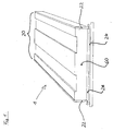
- FIG. 1 shows a start-up track 1 for ski jumps, which consists only of a cooling starting track 20.
- Bottom 24 and side walls 22 of the cooling run-track 20 form a box-shaped profile.
- Snow 60, natural snow or artificial snow or a mixture of both, can be introduced into the cooling starting track 20.
- the distance of the side walls 22 is chosen so that in the filled snow two ruts can be formed in the space required for ski jumping. On the other hand, the distance of the side walls 22 should not go well beyond the extent required to keep the cooling snow amount as low as possible. Ideally, a distance of about 50 cm appears for the side walls 22.
- the cooling device 26 is provided, which can be realized for example by a flowed through by a coolant pipe plant.
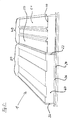
- FIG. 2 shows a run-in track 1 consisting of a cooling inrun track 20 and a directly adjacent arranged Alternativanlaufspur 40.
- the cooling inrun track 20 corresponds to the in FIG. 1 shown.
- the alternative ruts 50 and 51 of the alternative start-up track 40 have a sliding surface so that the alternative start-up track can be operated without snow.
- the width and spacing of the alternative starting ruts are selected according to the requirements of ski jumping.
- a track interior width of about 13.5 cm and a distance between the center lines of the track grooves of 32 cm is selected.
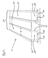
- FIG. 3 shows a run-up track 1, which consists of a cooling run-track 20, wherein the cooling run-up track 20 is formed of two parallel adjacent cooling grooves 30 and 31.
- the two cooling grooves 30 and 31 are in turn formed from the walls 22 and the bottom 24.
- the distance b of the walls 22 of a cooling raceway 30 or 31 is selected so that the cooling raceway can accommodate a jump skis so that laterally for the purposes of ski jumping sufficient play remains.
- Particularly favorable is a width b of 13 to 14 cm.
- the cooling grooves 30 and 31 are filled with natural and / or artificial snow 60. Since only the preferably 13 to 14 cm wide cooling grooves 30 and 31, but not the gap between the two cooling grooves with snow 60 must be filled, the need for snow 60 is comparatively low. In the FIG. 3 Thus, cooling intake track 20 shown permits minimizing the amount of snow required for two skipping boats, since only the two cooling ramp grooves 30 and 31 provided for each skip must be filled with snow. On the bottom 24 of the cooling grooves 30 and 31 is the cooling device 26, which ensures that the snow in the cooling grooves 30 and 31 60 is maintained even with changing outside temperatures.
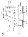
- FIG. 4 shows a run-in track 1, which consists of a cooling start track 20 similar to the in FIG. 3 shown consists.
- the cooling device 26 is mounted not only on the floor 24, but on the floor 24 and on the side walls 22.
- the cooling grooves 30 and 31 preferably have a depth of 25 cm and a width b of 13 cm and a mutual distance d of 32 cm.
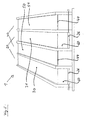
- FIG. 10 shows a start-up track representing a combination of a cooling start track 20 and an alternate start track 40.
- Cooling inrun track 20 and alternative inrun track 40 are arranged offset in one another, that is, in the horizontal direction, cooling grooves 30 and 31 alternate with alternative ruts 50 and 51.
- FIG. 5 there is a cooling lane 30 on the left, an alternative lane 50 on the right, a cooling lane 31 on the right next to it, and an alternative lane 51 on the far right.
- the staggered arrangement of cooling track 20 and Altemativanlaufspur 40 allows to accommodate the two starting tracks on minimum width.
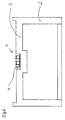
- FIG. 6 shows a SchanzenbauMechharm 2 with a Schanzendeckplatte 3 in which a run-up channel 4 is inserted.
- the trained as a module inrun track 1 can be sunk.
- the snow surface in the cooling grooves 30 and 31 and the bottom 44 of the alternative ruts 50 and 51 at the same height as the surface of the Schanzendeckplatte 3.
- the characteristic for the ski jump start parabola for the inrun track 1 is the same as that for the surface of the Schanzendeckplatte 3.
- the starting parabola is not changed by the use of the inrun 1 against the normal ski surface.
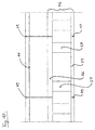
- FIG. 7 shows a run-in track 1 with mutually offset cooling and Alternativanlaufspur in cross section.
- the bottoms 44 of the alternative ruts 50 and 51 are underlaid with dynamometric plates 46.
- the Dynamometrieplatten 46 the force pulses developed by the ski jumpers can be measured, and separately for each talus. The measurement can be carried out, for example, by piezoelectric elements integrated into the dynamometric plates 46. Accurate measurement requires mechanical decoupling of the bottoms 44 of the alternative track grooves 50 and 51 and the dynamometry plates 46 from the lateral enclosure of the alternative track grooves 50 and 51.
- This mechanical decoupling may be achieved, for example, by a narrow gap 48 between the dynamometric plate 46 and the walls 22 and 42 , The gap is preferably 2.5 mm wide.
- the complete mechanical decoupling of the dynamometric plates also requires a mechanical decoupling 47 of coolant lines optionally passing through the dynamometric plate.
- the decoupling 47 can be achieved for example by flexible coolant lines.
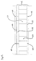
- FIG. 8 shows a longitudinal section through an alternative ruts 50 or 51, wherein the bottom 44 of the alternative ruts 50 is backed by dynamometry plates 46.
- FIG. 8 shows in the middle a complete Dynamometrieplatte 46 and right and left adjacent Dynamometrieplatten 46 each half.
- the dynamometry plates 46 consist of a bottom plate 55, a cover plate 56, and force sensors 57 mounted therebetween.
- the force sensors may include, for example, piezoelectric elements.
- the bottom plate 55 is fixed on the ski surface or on the module carrier.
- the cover plate is non-positively connected to the bottom of the alternative rut.
- the dynamometric plates are mechanically decoupled in the start-up direction at regular intervals.
- the mechanical decoupling can be achieved by a narrow gap 49 between two successive Dynamometrieplatten 46. Preferably, the gap is a few millimeters wide.
- the mechanical decoupling in the start-up direction allows an analysis of the bounce developed by the Springer, which is resolved by time and place.
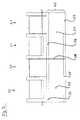
- FIG. 9 shows a mutually offset cooling and Alternativanlaufspur 20, 40.
- the left cooling groove 30 and the left alternative furrow 50 are underlaid by a common Dynamometrieplatte 46.
- the right cooling groove 31 and the right alternative groove 51 have a common dynamometric plate 46.
- the mechanical decoupling occurs between the middle tracks 50 and 31 through the gap 48.
- FIG. 10 shows a longitudinal section along an alternative trough 50 or 51 in a run-in track according to FIG. 9 , Due to the required depth of the cooling grooves 30 and 31, the overall structure is correspondingly higher. Also in this construction, the dynamometric plates 46 are mechanically decoupled in the longitudinal direction through narrow gaps 49.
- the above-described invention achieves a number of advantages.
- a run-in track of snow or ice is provided, which is far less dependent on the weather conditions than previously known tarnishing tracks.
- the combination with the Altemativanlaufspur makes the inrun track even without snow and therefore usable all year round.
- the inrun track according to the invention can also be integrated into existing ski jumping facilities, especially when the inrun track according to the invention is designed as a module.
- the connection with the dynamometric plates allows a particularly accurate analysis of the force impulses developed by the ski jumper.
- the inrun track according to the invention is particularly well suited for training purposes.
Landscapes
- Engineering & Computer Science (AREA)
- Architecture (AREA)
- Civil Engineering (AREA)
- Structural Engineering (AREA)
- Thermal Sciences (AREA)
- Mechanical Engineering (AREA)
- Physics & Mathematics (AREA)
- General Engineering & Computer Science (AREA)
- Turbine Rotor Nozzle Sealing (AREA)
- Glass Compositions (AREA)
- Wind Motors (AREA)
- Road Paving Structures (AREA)
- Compositions Of Macromolecular Compounds (AREA)
- Transition And Organic Metals Composition Catalysts For Addition Polymerization (AREA)
Claims (13)
- Piste d'élan (1) pour tremplins de saut à ski, la piste d'élan (1) comportant au moins une piste d'élan réfrigérante (20), ladite piste d'élan réfrigérante comportant au moins deux parois (22) et au moins un fond (24), la neige (60), en particulier de la neige artificielle ou un mélange de neige artificielle et de neige naturelle, pouvant être déposée dans la piste d'élan réfrigérante (20), et un dispositif de refroidissement (26) étant prévu pour le refroidissement de la piste d'élan réfrigérante (20), caractérisée en ce qu'en plus de ladite au moins une piste d'élan réfrigérante (20), il est prévu une piste d'élan alternative (40), ladite piste d'élan alternative (40) comportant une surface de glissement, en particulier des poils de glissement, en métal et/ou en céramique et/ou en verre et/ou dans d'autres matériaux, de telle sorte que la piste d'élan alternative (40) peut être utilisée sans couche de neige.
- Piste d'élan (1) pour tremplins de saut à ski selon la revendication 1, caractérisée en ce que ladite au moins une piste d'élan réfrigérante (20) comporte une paire de goulottes (30, 31) qui s'étendent parallèlement l'une à côté de l'autre, les goulottes (30, 31) de la piste réfrigérante ayant une section sensiblement en forme de U, la neige (60) pouvant être déposée dans les goulottes (30, 31) de la piste réfrigérante, et lesdites goulottes (30, 31) pouvant être refroidies par le dispositif de refroidissement (26).
- Piste d'élan (1) pour tremplins de saut à ski selon la revendication 2, caractérisée en ce que le dispositif de refroidissement (26) est prévu sur les fonds (24) et/ou sur les parois (22) des goulottes (30, 31) de la piste réfrigérante, en particulier en ce que le dispositif de refroidissement (26) est intégré dans les fonds (24) et/ou dans les parois (22).
- Piste d'élan (1) pour tremplins de saut à ski selon la revendication 2 ou 3, caractérisée en ce que la largeur (b) des goulottes (30, 31) de la piste réfrigérante est choisie de telle sorte que les goulottes (30, 31) de la piste réfrigérante peuvent recevoir chacune un ski de saut.
- Piste d'élan (1) pour tremplins de saut à ski selon l'une quelconque des revendications précédentes, caractérisée en ce que la piste d'élan alternative (40) comporte une paire de goulottes (50, 51) qui s'étendent parallèlement l'une à côté de l'autre, les fonds (44) desdites goulottes (50, 51) comportant la surface de glissement, en particulier les poils de glissement en métal et/ou en céramique et/ou en verre et/ou dans d'autres matériaux.
- Piste d'élan (1) pour tremplins de saut à ski selon l'une quelconque des revendications précédentes, caractérisée en ce que la neige peut être déposée dans la piste d'élan réfrigérante (20) sur une hauteur telle que la surface de la neige est à la même hauteur que le fond (44) de la piste d'élan alternative (40).
- Piste d'élan (1) pour tremplins de saut à ski selon la revendication 5 ou 6, caractérisée en ce qu'il est prévu une piste d'élan réfrigérante (20), formée par deux goulottes (30, 31), et une piste d'élan alternative (40), formée par deux goulottes (50, 51), et en ce que la piste d'élan réfrigérante (20) et la piste d'élan alternative (40) sont disposées en étant décalées l'une dans l'autre, de telle sorte qu'une goulotte (50) de la piste alternative se situe entre les deux goulottes (30, 31) de la piste réfrigérante, et une goulotte (31) de la piste réfrigérante se situe entre les deux goulottes (50, 51) de la piste alternative.
- Piste d'élan (1) pour tremplins de saut à ski selon l'une quelconque des revendications précédentes, caractérisée en ce que la piste d'élan (1) en forme de module peut être enfoncée dans un canal de piste (4), ménagé dans la plaque de recouvrement (3) du tremplin.
- Piste d'élan (1) pour tremplins de saut à ski selon l'une quelconque des revendications 5 à 8, caractérisée en ce que dans la zone de saut de la piste d'élan (1), de préférence sur les derniers 11 mètres avant le saut, des plaques dynamométriques (46) sont mises en place en dessous des fonds (44) des goulottes (50, 51) de la piste alternative, la force développée par le sauteur pouvant être mesurée par les plaques dynamométriques (46).
- Piste d'élan (1) pour tremplins de saut à ski selon la revendication précédente, caractérisée en ce que les fonds (44) des goulottes (50, 51) de la piste alternative et les plaques dynamométriques (46), disposés en dessous desdits fonds, sont découplés latéralement par voie mécanique, le découplage mécanique étant obtenu de préférence par une fente (48) sur les deux côtés des fonds (44) et des plaques dynamométriques (46).
- Piste d'élan (1) pour tremplins de saut à ski selon l'une quelconque des deux revendications précédentes, caractérisée en ce que les plaques dynamométriques (46) comportent une plaque de fond (55), une plaque de recouvrement (56) et des capteurs de force (57) situés entre celles-ci, la plaque de fond (55) étant assemblée de manière fixe au tremplin (2), la plaque de recouvrement (56) étant assemblée de manière fixe au fond (44) des goulottes de la piste alternative, les plaques de recouvrement (56) s'étendant de préférence à peu près sur toute la largeur des fonds (44) des goulottes (50, 51) de la piste alternative.
- Piste d'élan (1) pour tremplins de saut à ski selon la revendication 7, caractérisée en ce que dans la zone de saut de la piste d'élan, de préférence sur les derniers 11 mètres, des plaques dynamométriques (46) sont mises en place en dessous des goulottes (30, 31, 50, 51) des pistes et sont associées conjointement à une goulotte extérieure (30, 51) et à la goulotte intérieure (31, 50) respectivement adjacente, un découplage (58) mécanique étant prévu entre les goulottes intérieures (31, 50), lequel est réalisé par une fente (58).
- Piste d'élan (1) pour tremplins de saut à ski selon l'une quelconque des revendications 9 à 12, caractérisée en ce que les plaques dynamométriques (46), disposées à distances régulières les unes des autres dans la direction de l'élan, de préférence à des distances d'un mètre, sont découplées mécaniquement, le découplage étant réalisé de préférence dans chaque cas par une fente (49).
Applications Claiming Priority (2)
| Application Number | Priority Date | Filing Date | Title |
|---|---|---|---|
| DE10323250 | 2003-05-22 | ||
| DE10323250A DE10323250B4 (de) | 2003-05-22 | 2003-05-22 | Anlaufspur für Skisprungschanzen |
Publications (2)
| Publication Number | Publication Date |
|---|---|
| EP1479986A1 EP1479986A1 (fr) | 2004-11-24 |
| EP1479986B1 true EP1479986B1 (fr) | 2010-12-29 |
Family
ID=33039280
Family Applications (1)
| Application Number | Title | Priority Date | Filing Date |
|---|---|---|---|
| EP04011306A Expired - Lifetime EP1479986B1 (fr) | 2003-05-22 | 2004-05-12 | Piste de départ pour un tremplin de saut à ski |
Country Status (3)
| Country | Link |
|---|---|
| EP (1) | EP1479986B1 (fr) |
| AT (1) | ATE493620T1 (fr) |
| DE (2) | DE10323250B4 (fr) |
Families Citing this family (21)
| Publication number | Priority date | Publication date | Assignee | Title |
|---|---|---|---|---|
| WO2007079967A1 (fr) * | 2005-12-28 | 2007-07-19 | Rehau Ag + Co | Dispositif pour infrastructure de ski |
| DE102005062710A1 (de) * | 2005-12-28 | 2007-07-05 | Rehau Ag + Co. | Vorrichtung für eine Skianlage |
| DE102005062711A1 (de) * | 2005-12-28 | 2007-07-05 | Rehau Ag + Co. | Skilaufspur für den Sommerbetrieb künstlicher Skianlagen |
| DE102007038383A1 (de) | 2007-08-14 | 2009-02-26 | Bernhard Freund | Vorrichtung zur Bearbeitung von Skisprungschanzen-Anlaufspuren |
| DE202007019524U1 (de) | 2007-12-17 | 2013-04-24 | Ceramtec-Etec Gmbh | Gleitflächenelement als Einspursystem für Skisprunganlagen |
| DE202007019523U1 (de) | 2007-12-17 | 2013-04-24 | Ceramtec-Etec Gmbh | Gleitflächenelement als Einspursystem für Skisprunganlagen |
| DE202007019522U1 (de) | 2007-12-17 | 2013-04-24 | Ceramtec-Etec Gmbh | Gleitflächenelement als Einspursystem für Skisprunganlagen |
| DE202007019525U1 (de) | 2007-12-17 | 2013-04-24 | Ceramtec-Etec Gmbh | Gleitflächenelement als Einspursystem für Skisprunganlagen |
| DE102007060755A1 (de) | 2007-12-17 | 2009-06-18 | ETEC Gesellschaft für technische Keramik mbH | Gleitflächenelement für Schisprunganlagen |
| DE102008017126A1 (de) | 2008-04-03 | 2009-10-08 | Anlagenbau Haas Gmbh | Skisprungschanze und Verfahren zur Erzeugung einer Anlaufspur |
| DE102008020439B3 (de) * | 2008-04-24 | 2009-10-22 | Ceramtec-Etec Gmbh | Gleitflächenelement für Schisprunganlagen |
| DE102009052924B3 (de) * | 2009-11-12 | 2011-05-12 | Riedel, Peter, Dipl.-Ing. (FH) | Vorrichtung zur Bearbeitung von Skisprungschanzen-Anlaufspuren |
| SE534323C2 (sv) * | 2009-11-16 | 2011-07-12 | Icehotel Ab | Förfarande vid och anordning för tillverkning av byggelement av konstsnö |
| DE102010007440A1 (de) | 2010-02-10 | 2011-09-29 | Haas Gmbh Anlagenbau | Skisprungschanze und Verfahren zur Erzeugung einer Anlaufspur |
| AT11868U3 (de) * | 2011-01-14 | 2012-03-15 | Rehau Ag & Co | Vorrichtung für eine skianlage |
| DE102012018498A1 (de) * | 2012-04-13 | 2013-10-17 | Ceramtec-Etec Gmbh | Sprungschanzenaufbau |
| DE102012014964A1 (de) | 2012-07-30 | 2014-05-15 | Rüdiger Schunk | Skisprung-Anlaufspur für Skisprungschanzen |
| EP2927624B1 (fr) * | 2014-03-27 | 2019-09-04 | Peter Riedel Patent UG (haftungsbeschränkt) | Système de refroidissement de piste d'élan pour tremplin de saut à ski |
| DE102017005662A1 (de) * | 2017-06-14 | 2018-12-20 | Molibso Entwicklungs- Und Vertriebs Gmbh | Messvorrichtung zur Untersuchung von Gleitbrettern |
| DE102018001045A1 (de) | 2018-02-09 | 2019-08-14 | Rüdiger Schunk | Spursystem für Skisprungschanzen |
| AT17715U1 (de) * | 2021-11-08 | 2022-12-15 | Alpina Sicherheitssysteme Gmbh | Anlaufspur |
Family Cites Families (10)
| Publication number | Priority date | Publication date | Assignee | Title |
|---|---|---|---|---|
| DE7907963U1 (de) * | 1981-01-15 | Plenk, Anton, 8222 Ruhpolding | Skikunstlaufbahn | |
| CH174772A (de) * | 1933-11-25 | 1935-01-31 | Buss Ag | Gefriereinrichtung für künstliche Eisbahnen. |
| CH174551A (de) * | 1933-12-21 | 1935-01-15 | Sulzer Ag | Künstliche Eisbahn. |
| GB876979A (en) * | 1959-07-01 | 1961-09-06 | Henry Spence And Son London Lt | Improvements in and relating to physical training devices |
| FI62223C (fi) * | 1979-01-29 | 1982-12-10 | Porkka Oy Pentti | Element |
| DE3784903T2 (de) * | 1986-12-18 | 1993-06-24 | Michael Anthony Smithard | Lerngeraet. |
| FI883768A7 (fi) * | 1987-08-17 | 1989-02-18 | Hermsdorf Keramik Veb | Glidelement foer vintersportspaor och -banor samt foerfarande foer dess framstaellning. |
| CH691621A5 (de) * | 1995-09-26 | 2001-08-31 | Langhans & Schondelmaier Ag | Mattenartiger Wärmetauscher für Kühl- und/oder Heizzwecke. |
| DE19843901C2 (de) * | 1998-05-11 | 2000-06-08 | Morent Ralf | Verfahren zur Haltbarmachung von Schnee und Kühlmatteneinrichtung zur Durchführung des Verfahrens |
| DE20011567U1 (de) * | 2000-07-01 | 2000-09-28 | Winterlich, Joachim, 08340 Beierfeld | Anlaufbahn für Skisprungschanzen |
-
2003
- 2003-05-22 DE DE10323250A patent/DE10323250B4/de not_active Expired - Fee Related
-
2004
- 2004-05-12 EP EP04011306A patent/EP1479986B1/fr not_active Expired - Lifetime
- 2004-05-12 AT AT04011306T patent/ATE493620T1/de active
- 2004-05-12 DE DE502004012040T patent/DE502004012040D1/de not_active Expired - Lifetime
Also Published As
| Publication number | Publication date |
|---|---|
| EP1479986A1 (fr) | 2004-11-24 |
| DE10323250B4 (de) | 2005-07-28 |
| DE10323250A1 (de) | 2004-12-16 |
| DE502004012040D1 (de) | 2011-02-10 |
| ATE493620T1 (de) | 2011-01-15 |
Similar Documents
| Publication | Publication Date | Title |
|---|---|---|
| EP1479986B1 (fr) | Piste de départ pour un tremplin de saut à ski | |
| DE2939605A1 (de) | Wettkampfbahn | |
| EP2452018B1 (fr) | Plaque d'appui présentant des parties de plaque et des cavités réceptrices carrées disposées en rangs et en colonnes de manière décalée les unes par rapport aux autres | |
| EP0259406B1 (fr) | Bloc de roulement et piste de roulement composes de blocs de roulement | |
| EP0304008A1 (fr) | Pièce de glissement pour pistes et parcours de sports d'hiver et son procédé de fabrication | |
| EP2742183B1 (fr) | Plaque de glisse et système de plaque de glisse pour un tremplin de saut à ski | |
| WO1998004778A1 (fr) | Terrain de sport, notamment terrain de football, et procede pour deplacer horizontalement ledit terrain | |
| DE102007060755A1 (de) | Gleitflächenelement für Schisprunganlagen | |
| EP0435050A1 (fr) | Plaque de fond en matière plastique | |
| AT364726B (de) | Laufflaeche fuer langlaufski | |
| EP2927624B1 (fr) | Système de refroidissement de piste d'élan pour tremplin de saut à ski | |
| DE19645777C2 (de) | Kastenbeschicker | |
| EP1078209A1 (fr) | Procede et dispositif pour la conservation de la neige | |
| DE202007017583U1 (de) | Gleitflächenelement für Schisprunganlagen | |
| DE2942527A1 (de) | Erdbeer-mulch-geraetesatz | |
| DE102004060818B4 (de) | Bodenaufbau für Indoor-Skihallen | |
| DE2044471A1 (fr) | ||
| DE19843901A1 (de) | Verfahren und Einrichtung zur Haltbarmachung von Schnee | |
| AT392992B (de) | Verfahren zum verfestigen einer insbesondere geneigten schneedecke und eine einrichtung zur durchfuehrung des verfahrens | |
| AT513884B1 (de) | Anlaufelement für Schisprungschanzen | |
| EP2650436B1 (fr) | Tremplin de saut à ski | |
| AT12091U1 (de) | Leitelement für kleintierschutzeinrichtungen | |
| EP2902081B1 (fr) | Système de piste d'élan pour tremplin de saut à ski | |
| DE3133138A1 (de) | Grubberschar | |
| DE102015105772B3 (de) | Gleitelement für eine Wintersport-Gleitbahn, Wintersport-Gleitbahn sowie Verwendung eines dafür geeigneten Gleitmaterials |
Legal Events
| Date | Code | Title | Description |
|---|---|---|---|
| PUAI | Public reference made under article 153(3) epc to a published international application that has entered the european phase |
Free format text: ORIGINAL CODE: 0009012 |
|
| AK | Designated contracting states |
Kind code of ref document: A1 Designated state(s): AT BE BG CH CY CZ DE DK EE ES FI FR GB GR HU IE IT LI LU MC NL PL PT RO SE SI SK TR |
|
| AX | Request for extension of the european patent |
Extension state: AL HR LT LV MK |
|
| 17P | Request for examination filed |
Effective date: 20050513 |
|
| AKX | Designation fees paid |
Designated state(s): AT BE BG CH CY CZ DE DK EE ES FI FR GB GR HU IE IT LI LU MC NL PL PT RO SE SI SK TR |
|
| RAP1 | Party data changed (applicant data changed or rights of an application transferred) |
Owner name: RIEDEL, PETER |
|
| RIN1 | Information on inventor provided before grant (corrected) |
Inventor name: RIEDEL, PETER JOACHIM Inventor name: RIEDEL, ANGELIKA |
|
| 17Q | First examination report despatched |
Effective date: 20090527 |
|
| GRAP | Despatch of communication of intention to grant a patent |
Free format text: ORIGINAL CODE: EPIDOSNIGR1 |
|
| GRAS | Grant fee paid |
Free format text: ORIGINAL CODE: EPIDOSNIGR3 |
|
| GRAA | (expected) grant |
Free format text: ORIGINAL CODE: 0009210 |
|
| AK | Designated contracting states |
Kind code of ref document: B1 Designated state(s): AT BE BG CH CY CZ DE DK EE ES FI FR GB GR HU IE IT LI LU MC NL PL PT RO SE SI SK TR |
|
| REG | Reference to a national code |
Ref country code: GB Ref legal event code: FG4D Free format text: NOT ENGLISH |
|
| REG | Reference to a national code |
Ref country code: CH Ref legal event code: EP |
|
| REG | Reference to a national code |
Ref country code: CH Ref legal event code: NV Representative=s name: BOVARD AG PATENTANWAELTE |
|
| REG | Reference to a national code |
Ref country code: IE Ref legal event code: FG4D Free format text: LANGUAGE OF EP DOCUMENT: GERMAN |
|
| REF | Corresponds to: |
Ref document number: 502004012040 Country of ref document: DE Date of ref document: 20110210 Kind code of ref document: P |
|
| REG | Reference to a national code |
Ref country code: DE Ref legal event code: R096 Ref document number: 502004012040 Country of ref document: DE Effective date: 20110210 |
|
| REG | Reference to a national code |
Ref country code: CH Ref legal event code: PFA Owner name: RIEDEL, PETER Free format text: RIEDEL, PETER#AM GRENZHANG 18#08355 RITTERSGRUEN OT TELLERHAEUSER (DE) -TRANSFER TO- RIEDEL, PETER#AM GRENZHANG 18#08355 RITTERSGRUEN OT TELLERHAEUSER (DE) |
|
| REG | Reference to a national code |
Ref country code: NL Ref legal event code: VDEP Effective date: 20101229 |
|
| PG25 | Lapsed in a contracting state [announced via postgrant information from national office to epo] |
Ref country code: BG Free format text: LAPSE BECAUSE OF FAILURE TO SUBMIT A TRANSLATION OF THE DESCRIPTION OR TO PAY THE FEE WITHIN THE PRESCRIBED TIME-LIMIT Effective date: 20110329 Ref country code: SE Free format text: LAPSE BECAUSE OF FAILURE TO SUBMIT A TRANSLATION OF THE DESCRIPTION OR TO PAY THE FEE WITHIN THE PRESCRIBED TIME-LIMIT Effective date: 20101229 Ref country code: FI Free format text: LAPSE BECAUSE OF FAILURE TO SUBMIT A TRANSLATION OF THE DESCRIPTION OR TO PAY THE FEE WITHIN THE PRESCRIBED TIME-LIMIT Effective date: 20101229 Ref country code: SI Free format text: LAPSE BECAUSE OF FAILURE TO SUBMIT A TRANSLATION OF THE DESCRIPTION OR TO PAY THE FEE WITHIN THE PRESCRIBED TIME-LIMIT Effective date: 20101229 Ref country code: CY Free format text: LAPSE BECAUSE OF FAILURE TO SUBMIT A TRANSLATION OF THE DESCRIPTION OR TO PAY THE FEE WITHIN THE PRESCRIBED TIME-LIMIT Effective date: 20101229 |
|
| RAP2 | Party data changed (patent owner data changed or rights of a patent transferred) |
Owner name: PETER RIEDEL PATENT UG (HAFTUNGSBESCHRAENKT) |
|
| REG | Reference to a national code |
Ref country code: CH Ref legal event code: PUE Owner name: PETER RIEDEL PATENT UG (HAFTUNGSBESCHRAENKT) Free format text: RIEDEL, PETER#AM GRENZHANG 18#08355 RITTERSGRUEN OT TELLERHAEUSER (DE) -TRANSFER TO- PETER RIEDEL PATENT UG (HAFTUNGSBESCHRAENKT)#AM GRENZHANG 18#08359 BREITENBRUNN / OT TELLERHAEUSER (DE) |
|
| REG | Reference to a national code |
Ref country code: IE Ref legal event code: FD4D |
|
| PG25 | Lapsed in a contracting state [announced via postgrant information from national office to epo] |
Ref country code: ES Free format text: LAPSE BECAUSE OF FAILURE TO SUBMIT A TRANSLATION OF THE DESCRIPTION OR TO PAY THE FEE WITHIN THE PRESCRIBED TIME-LIMIT Effective date: 20110409 Ref country code: GR Free format text: LAPSE BECAUSE OF FAILURE TO SUBMIT A TRANSLATION OF THE DESCRIPTION OR TO PAY THE FEE WITHIN THE PRESCRIBED TIME-LIMIT Effective date: 20110330 Ref country code: CZ Free format text: LAPSE BECAUSE OF FAILURE TO SUBMIT A TRANSLATION OF THE DESCRIPTION OR TO PAY THE FEE WITHIN THE PRESCRIBED TIME-LIMIT Effective date: 20101229 Ref country code: PT Free format text: LAPSE BECAUSE OF FAILURE TO SUBMIT A TRANSLATION OF THE DESCRIPTION OR TO PAY THE FEE WITHIN THE PRESCRIBED TIME-LIMIT Effective date: 20110429 Ref country code: EE Free format text: LAPSE BECAUSE OF FAILURE TO SUBMIT A TRANSLATION OF THE DESCRIPTION OR TO PAY THE FEE WITHIN THE PRESCRIBED TIME-LIMIT Effective date: 20101229 |
|
| PGFP | Annual fee paid to national office [announced via postgrant information from national office to epo] |
Ref country code: FR Payment date: 20110603 Year of fee payment: 8 |
|
| REG | Reference to a national code |
Ref country code: DE Ref legal event code: R082 Ref document number: 502004012040 Country of ref document: DE Representative=s name: ADARES PATENT- UND RECHTSANWAELTE REININGER & , DE |
|
| PG25 | Lapsed in a contracting state [announced via postgrant information from national office to epo] |
Ref country code: PL Free format text: LAPSE BECAUSE OF FAILURE TO SUBMIT A TRANSLATION OF THE DESCRIPTION OR TO PAY THE FEE WITHIN THE PRESCRIBED TIME-LIMIT Effective date: 20101229 Ref country code: NL Free format text: LAPSE BECAUSE OF FAILURE TO SUBMIT A TRANSLATION OF THE DESCRIPTION OR TO PAY THE FEE WITHIN THE PRESCRIBED TIME-LIMIT Effective date: 20101229 Ref country code: SK Free format text: LAPSE BECAUSE OF FAILURE TO SUBMIT A TRANSLATION OF THE DESCRIPTION OR TO PAY THE FEE WITHIN THE PRESCRIBED TIME-LIMIT Effective date: 20101229 Ref country code: RO Free format text: LAPSE BECAUSE OF FAILURE TO SUBMIT A TRANSLATION OF THE DESCRIPTION OR TO PAY THE FEE WITHIN THE PRESCRIBED TIME-LIMIT Effective date: 20101229 |
|
| REG | Reference to a national code |
Ref country code: DE Ref legal event code: R082 Ref document number: 502004012040 Country of ref document: DE Representative=s name: ADARES PATENT- UND RECHTSANWAELTE REININGER & , DE Effective date: 20110819 Ref country code: DE Ref legal event code: R081 Ref document number: 502004012040 Country of ref document: DE Owner name: PETER RIEDEL PATENT UG (HAFTUNGSBESCHRAENKT), DE Free format text: FORMER OWNER: RIEDEL, PETER, DIPL.-ING., 08359 BREITENBRUNN, DE Effective date: 20110819 |
|
| PG25 | Lapsed in a contracting state [announced via postgrant information from national office to epo] |
Ref country code: DK Free format text: LAPSE BECAUSE OF FAILURE TO SUBMIT A TRANSLATION OF THE DESCRIPTION OR TO PAY THE FEE WITHIN THE PRESCRIBED TIME-LIMIT Effective date: 20101229 Ref country code: IE Free format text: LAPSE BECAUSE OF FAILURE TO SUBMIT A TRANSLATION OF THE DESCRIPTION OR TO PAY THE FEE WITHIN THE PRESCRIBED TIME-LIMIT Effective date: 20101229 |
|
| PLBE | No opposition filed within time limit |
Free format text: ORIGINAL CODE: 0009261 |
|
| STAA | Information on the status of an ep patent application or granted ep patent |
Free format text: STATUS: NO OPPOSITION FILED WITHIN TIME LIMIT |
|
| BERE | Be: lapsed |
Owner name: RIEDEL, PETER Effective date: 20110531 |
|
| 26N | No opposition filed |
Effective date: 20110930 |
|
| PG25 | Lapsed in a contracting state [announced via postgrant information from national office to epo] |
Ref country code: MC Free format text: LAPSE BECAUSE OF NON-PAYMENT OF DUE FEES Effective date: 20110531 |
|
| GBPC | Gb: european patent ceased through non-payment of renewal fee |
Effective date: 20110512 |
|
| REG | Reference to a national code |
Ref country code: DE Ref legal event code: R097 Ref document number: 502004012040 Country of ref document: DE Effective date: 20110930 |
|
| PG25 | Lapsed in a contracting state [announced via postgrant information from national office to epo] |
Ref country code: BE Free format text: LAPSE BECAUSE OF NON-PAYMENT OF DUE FEES Effective date: 20110531 |
|
| PG25 | Lapsed in a contracting state [announced via postgrant information from national office to epo] |
Ref country code: IT Free format text: LAPSE BECAUSE OF FAILURE TO SUBMIT A TRANSLATION OF THE DESCRIPTION OR TO PAY THE FEE WITHIN THE PRESCRIBED TIME-LIMIT Effective date: 20101229 |
|
| PG25 | Lapsed in a contracting state [announced via postgrant information from national office to epo] |
Ref country code: GB Free format text: LAPSE BECAUSE OF NON-PAYMENT OF DUE FEES Effective date: 20110512 |
|
| REG | Reference to a national code |
Ref country code: FR Ref legal event code: ST Effective date: 20130131 |
|
| PG25 | Lapsed in a contracting state [announced via postgrant information from national office to epo] |
Ref country code: FR Free format text: LAPSE BECAUSE OF NON-PAYMENT OF DUE FEES Effective date: 20120531 |
|
| PG25 | Lapsed in a contracting state [announced via postgrant information from national office to epo] |
Ref country code: LU Free format text: LAPSE BECAUSE OF NON-PAYMENT OF DUE FEES Effective date: 20110512 |
|
| PG25 | Lapsed in a contracting state [announced via postgrant information from national office to epo] |
Ref country code: TR Free format text: LAPSE BECAUSE OF FAILURE TO SUBMIT A TRANSLATION OF THE DESCRIPTION OR TO PAY THE FEE WITHIN THE PRESCRIBED TIME-LIMIT Effective date: 20101229 |
|
| PG25 | Lapsed in a contracting state [announced via postgrant information from national office to epo] |
Ref country code: HU Free format text: LAPSE BECAUSE OF FAILURE TO SUBMIT A TRANSLATION OF THE DESCRIPTION OR TO PAY THE FEE WITHIN THE PRESCRIBED TIME-LIMIT Effective date: 20101229 |
|
| REG | Reference to a national code |
Ref country code: DE Ref legal event code: R082 Ref document number: 502004012040 Country of ref document: DE Representative=s name: ADARES PATENT- UND RECHTSANWAELTE REININGER & , DE |
|
| REG | Reference to a national code |
Ref country code: DE Ref legal event code: R082 Ref document number: 502004012040 Country of ref document: DE Representative=s name: ADARES PATENT- UND RECHTSANWAELTE REININGER & , DE Effective date: 20140918 Ref country code: DE Ref legal event code: R081 Ref document number: 502004012040 Country of ref document: DE Owner name: PETER RIEDEL PATENT UG (HAFTUNGSBESCHRAENKT), DE Free format text: FORMER OWNER: PETER RIEDEL PATENT UG (HAFTUNGSBESCHRAENKT), 08359 BREITENBRUNN, DE Effective date: 20140918 |
|
| REG | Reference to a national code |
Ref country code: CH Ref legal event code: PCOW Free format text: NEW ADDRESS: SCHNEEBERGER STRASSE 49, 08340 SCHWARZENBERG (DE) |
|
| PGFP | Annual fee paid to national office [announced via postgrant information from national office to epo] |
Ref country code: CH Payment date: 20180523 Year of fee payment: 15 |
|
| PGFP | Annual fee paid to national office [announced via postgrant information from national office to epo] |
Ref country code: AT Payment date: 20180517 Year of fee payment: 15 |
|
| REG | Reference to a national code |
Ref country code: CH Ref legal event code: PL |
|
| REG | Reference to a national code |
Ref country code: AT Ref legal event code: MM01 Ref document number: 493620 Country of ref document: AT Kind code of ref document: T Effective date: 20190512 |
|
| PG25 | Lapsed in a contracting state [announced via postgrant information from national office to epo] |
Ref country code: CH Free format text: LAPSE BECAUSE OF NON-PAYMENT OF DUE FEES Effective date: 20190531 Ref country code: LI Free format text: LAPSE BECAUSE OF NON-PAYMENT OF DUE FEES Effective date: 20190531 Ref country code: AT Free format text: LAPSE BECAUSE OF NON-PAYMENT OF DUE FEES Effective date: 20190512 |
|
| PGFP | Annual fee paid to national office [announced via postgrant information from national office to epo] |
Ref country code: DE Payment date: 20230502 Year of fee payment: 20 |
|
| REG | Reference to a national code |
Ref country code: DE Ref legal event code: R081 Ref document number: 502004012040 Country of ref document: DE Owner name: PETER RIEDEL GMBH, DE Free format text: FORMER OWNER: PETER RIEDEL PATENT UG (HAFTUNGSBESCHRAENKT), 08340 SCHWARZENBERG, DE |
|
| REG | Reference to a national code |
Ref country code: DE Ref legal event code: R071 Ref document number: 502004012040 Country of ref document: DE |