EP1479969A2 - Seilaufhänger für Leuchten - Google Patents
Seilaufhänger für Leuchten Download PDFInfo
- Publication number
- EP1479969A2 EP1479969A2 EP04011705A EP04011705A EP1479969A2 EP 1479969 A2 EP1479969 A2 EP 1479969A2 EP 04011705 A EP04011705 A EP 04011705A EP 04011705 A EP04011705 A EP 04011705A EP 1479969 A2 EP1479969 A2 EP 1479969A2
- Authority
- EP
- European Patent Office
- Prior art keywords
- cable
- lamp
- hanger
- housing
- lateral displacement
- Prior art date
- Legal status (The legal status is an assumption and is not a legal conclusion. Google has not performed a legal analysis and makes no representation as to the accuracy of the status listed.)
- Granted
Links
- 239000000725 suspension Substances 0.000 title claims abstract description 63
- 238000006073 displacement reaction Methods 0.000 claims abstract description 55
- 230000005484 gravity Effects 0.000 claims abstract description 10
- 238000009434 installation Methods 0.000 claims abstract description 6
- 238000009826 distribution Methods 0.000 description 6
- 210000000056 organ Anatomy 0.000 description 3
- 230000005540 biological transmission Effects 0.000 description 2
- 239000003795 chemical substances by application Substances 0.000 description 2
- 230000001788 irregular Effects 0.000 description 1
- 239000003550 marker Substances 0.000 description 1
- 239000000463 material Substances 0.000 description 1
- 230000004048 modification Effects 0.000 description 1
- 238000012986 modification Methods 0.000 description 1
- 230000002093 peripheral effect Effects 0.000 description 1
Images


Classifications
-
- F—MECHANICAL ENGINEERING; LIGHTING; HEATING; WEAPONS; BLASTING
- F21—LIGHTING
- F21V—FUNCTIONAL FEATURES OR DETAILS OF LIGHTING DEVICES OR SYSTEMS THEREOF; STRUCTURAL COMBINATIONS OF LIGHTING DEVICES WITH OTHER ARTICLES, NOT OTHERWISE PROVIDED FOR
- F21V21/00—Supporting, suspending, or attaching arrangements for lighting devices; Hand grips
- F21V21/10—Pendants, arms, or standards; Fixing lighting devices to pendants, arms, or standards
- F21V21/112—Fixing lighting devices to pendants
-
- F—MECHANICAL ENGINEERING; LIGHTING; HEATING; WEAPONS; BLASTING
- F21—LIGHTING
- F21Y—INDEXING SCHEME ASSOCIATED WITH SUBCLASSES F21K, F21L, F21S and F21V, RELATING TO THE FORM OR THE KIND OF THE LIGHT SOURCES OR OF THE COLOUR OF THE LIGHT EMITTED
- F21Y2103/00—Elongate light sources, e.g. fluorescent tubes
-
- F—MECHANICAL ENGINEERING; LIGHTING; HEATING; WEAPONS; BLASTING
- F21—LIGHTING
- F21Y—INDEXING SCHEME ASSOCIATED WITH SUBCLASSES F21K, F21L, F21S and F21V, RELATING TO THE FORM OR THE KIND OF THE LIGHT SOURCES OR OF THE COLOUR OF THE LIGHT EMITTED
- F21Y2113/00—Combination of light sources
Definitions
- the invention relates to a cable hanger for suspended luminaires with a holder for a vertical rope in the installation position for hanging a lamp in a cable support point and with a mounting area for mounting the lamp on the hanger, the attachment area being a center wherein means for based on the cable longitudinal direction lateral displacement of the cable support point relative to the center of the attachment area for the lamp or means related to the longitudinal extent an associated lamp lateral displacement of the Luminaire center of gravity relative to the cable support point of the Luminaire housing are provided.
- the invention relates to a lamp with a cable hanger.
- the luminaire housing in many Falls over two or four ropes on one blanket or another suspended horizontal beams, with the ropes from each other spaced attack on the lamp body.
- the assigned Rope holding points are mostly in the area of the frontal Ends of the lamp housing arranged so that this one have the greatest possible distance from each other.
- the rope holding point is the substantially point-shaped area of the rope on which the load transfer of the lamp housing on the rope, i. the point at which the Luminaire housing including cable hanger on the respective Rope load-bearing attacks.
- the rope hanger itself is here on the lamp with an associated mounting area connected, which has a center, thereby definable is that with a symmetric, i.
- cable hangers which generally by a strand-shaped, elongated suspension element are suspended, including within the meaning of the invention, wires or the like to be understood.
- the rope in different Transverse directions different to its longitudinal direction Have diameter and, for example in the manner of a Bandes be executed, in which case the support point in lies the central longitudinal axis of the band.
- Such inclinations of the lamp body can be separated fixed at the lamp to be mounted balance weights determining the target positions and target weights of the counterweights to achieve a horizontal layout of the
- the light is comparatively expensive.
- the invention is therefore based on the object, a lamp or to provide a device of a luminaire, by means of which even when a tilt of the suspension lamp causing asymmetrical weight distribution the lamp to simple Way horizontally alignable, the device on easy way to the light integratable and easy to produce is.
- the lateral displacement means comprises an eccentric element, by its rotation a lateral displacement of the cable support point and the center of the luminaire mounting area relative to each other or the rope support point and the center of gravity of a associated lamp housing is effected relative to each other.
- the object is achieved by a luminaire housing after the independent Claim 17 solved.
- Means be provided in relation to the longitudinal extent the luminaire's center of gravity in the transverse direction relative to the cable support point of the lamp to move. These means are preferably based on the lamp's longitudinal direction at least approximately or exactly at the height of the cable hanger arranged, without this is always mandatory.
- To adjust the horizontal position of the lamp for example in the housing integrated, sliding balance weights be provided, it can also be already existing Components, especially those with comparatively high Weight such as transformers, housing components or the like, be transversely displaceable to the housing transverse direction.
- the housing is in total in the transverse direction slidable to the cable suspension, for example by a suitable Training the luminaire suspension itself, because due the highPolises only relatively small Displacement paths are necessary for balancing.
- this has a lateral Relocation of the attachment area of the cable suspension relative to the cable support point of about 0.5 to about 5 mm, preferably in the range of 1 to 3 mm proved sufficient.
- the lateral displacement means may be associated with one Luminaire housing under lateral displacement of the same relative to the housing longitudinal direction, through the connecting line spaced rope support points is defined act.
- the Shifting means can thus directly or optionally even with the interposition of a transmission mechanism the luminaire housing act.
- the displacement means can thereby It is and will be particularly simple and robust thus also for suspension lamps with comparatively high weight used.
- the cable holder is designed as a cable feedthrough, which extends through the lateral displacement means.
- the cable feedthrough can be closed on all sides be.
- the cable hanger can thus be particularly compact be executed.
- the rope mount can be attached to the center of the hanger or on its longitudinal axis, which is parallel to the longitudinal direction the rope extends, be arranged, wherein the lateral displacement means be designed in such a way can that the rope holding point by pressing the displacement means in a direction perpendicular to the lamp's longitudinal direction positionally changeable.
- a balance is made thus not a change in position of the cable support point.
- the Displacement means upon actuation of the Displacement means by a rotational movement of the cable support point be arranged at the height of the axis of rotation.
- the lateral displacement means act on the cable holder or directly on the cable holder attack, so that under lateral displacement of the Cable holder relative to the housing longitudinal axis or a housing center plane the associated luminaire housing substantially or exactly horizontally alignable.
- the housing longitudinal axis is here by the line connecting the rope suspension points Are defined.
- each cable suspension of the lamp is a erfindnässes invention associated with lateral displacement means.
- a particularly easy access of the lateral displacement means is given when an actuator for the lateral Displacement of luminaire mounting area and cable holder relative to each other or generally the luminaire's center of gravity relative to the cable suspension at the upper end of the installation position Cable hanger is arranged.
- the shifting means is thereby easily accessible, regardless of which Luminaire side the respective operator the displacement means actuated.
- the actuator an attack area for a tool, which on the in installation position upper end of the cable hanger is arranged.
- the actuator but optionally also on the side of the lamp housing be arranged.
- the actuator may be configured such that at this the position of the lateral displacement means and thus at least qualitatively the displacement of wire suspension and Luminaire mounting area relative to each other is read.
- the actuator in a displacement means in Shape of an eccentric described below, the actuator have a mark, which also in the form of a Attack area for a tool such as in form of Slot can be executed, wherein the mark the eccentric axis can indicate, for example, by the slit-shaped Mark runs parallel to the eccentric axis.
- the lateral displacement means an eccentric element, wherein Rotation of the eccentric a lateral displacement of the Seilauf wher structurallys relative to the center of the luminaire mounting area is effected.
- the eccentric plane stands here preferably perpendicular to the longitudinal direction of the Rope. Due to the eccentric element are high torques and / or Forces to move the lamp relative to the cable suspension in a compact embodiment of the cable hanger possible.
- the displacement means consists only from an eccentric element acting directly on the housing and an actuator acting directly on it, the integral with each other or executed in several parts could be.
- the eccentric element can hereby by immediate Actuation of the component provided with the eccentric actuated be, the eccentric can also be actuated by an actuator become.
- a power transmission means such as in the form of a linkage or the like be provided.
- a particularly easy attachable to the lamp housing Cable hanger is given if this in installation position an upper and a lower hanger member attachable to each other are, at least the lower hanger part a cable holder and a mounting area for the luminaire housing having.
- the cable hanger can thereby particularly easy a fixing area of the housing are set, which for example, is designed as a passage opening, which partially or completely surrounds the cable hanger.
- the Attachment of the upper and lower hanger part can be detachable or permanent or insoluble.
- the Attachment by a screw connection the Helical longitudinal axis runs parallel to the eccentric rotation axis.
- the eccentric provided with an internally threaded Be provided hole.
- the upper and lower hanger part can be a screw lock or another suitable securing element so that the top and bottom hangers are always in sync be moved together.
- the support area the cable hanger for the luminaire housing if necessary mainly only a holding or support function may come, even with respect to the eccentric element variable in position, e.g. be rotatable.
- the rope holder can here as partially or all-sided closed cable entry be executed.
- a lateral Querterrorismsseinschnürung as a laterally open groove for receiving arranged a mounting region of the lamp housing be, wherein the groove may be designed as a circumferential groove.
- the lateral displacement means which in particular can be designed as an eccentric, at the top Hangers arranged or it attacks on this, so that provided with the eccentric component directly itself actuated by causing the lateral displacement is.
- the shift means but also on attack the lower hanger part.
- the lower suspension part has a in the upper hanger part engaging fastening area, in particular in the form of a threaded pin, wherein at the bottom Suspension member preferably centric to the threaded pin a Cable holder is provided, for example in the form of a Blind hole, which extends in the journal longitudinal direction, so that a rope end provided with a staple or the like the recess can be arranged and the rope through the threaded pin is feasible.
- the lateral displacement means comprise an actuating means or designed as such be in a direction transverse to the desired position of Rope or transverse, in particular perpendicular, to a rope passage of the cable hanger under relative change in position of the Cable suspension point to the center of the luminaire mounting area is displaceable.
- an actuating means can in Form of a screw to be executed, which on the cable suspension or a lamp housing area, which to the Rope suspension is displaced, is executed.
- the shifting agent can for example also be designed as a slide organ be, by a set screw transverse to the longitudinal direction of the rope is displaceable. The slider organ can do this on a suitable slide or a slide-like Housing area be stored.
- a slide organ can also arranged on the rope suspension means for the lamp housing serve as an end-to-end staple.
- the adjusting agent or the slider can hereby transverse to the longitudinal direction of the rope to be linearly movable.
- the actuator for the slider can in this case from a direction transverse to the rope longitudinal direction be operable, if necessary with the interposition of a force deflection of the slide also from a vertical direction, for example from the top of the lamp ago, be operable.
- the invention comprises a luminaire housing with an inventive Cable suspension.
- the luminaire housing can hereby the rope suspension in two vertically spaced planes surrounded, including the housing a mounting area for the Rope suspension has, in the installed position in a first vertical Height is arranged, above the same a cover may be provided, through which the lateral displacement means is actuated, for example by introducing a Tool in a recess of the cover, in which case included is that the displacement means roughly up Height of the cover completes.
- the displacement means also upwards or laterally from the Projecting housing.
- the cable suspension on a gear tray of Luminaire be attached, the device carrier more electrical Equipment or connections of the luminaire for the operation of the respective illuminant receives, such as electrical Connectors, transformers or the like.
- the invention is not on such an arrangement of the cable suspension limited to the luminaire housing.
- a particularly stable embodiment is when the attachment area of the housing as a U-profile shaped area executed, for example, a portion of a another profile.
- the U-profile is here with provided at least one receptacle for a cable suspension.
- the U-profile is mounted on the inner wall of a box profile or integrally connected thereto, wherein the box section a top, preferably removable, cover has. If necessary, the U-profile can also be made up of several profiles be composed, e.g. through two L-profiles.
- the box profile In this case, it preferably forms a circumferential substantially closed profile.
- the box profile can be essentially one have rectangular or square cross-section, without being limited thereto.
- the U-profile is here preferably flat on the inner walls of the box profile and therefore preferably conforms substantially to the cross-sectional shape of the box profile without this being always mandatory necessary is. This is a simple attachment of Rope suspension with high rigidity of the luminaire housing area or device carrier given.
- the U-profile can be in the Essentially over the longitudinal extent of the respective housing part such as B. a device carrier, the U-profile Optionally, it may also be associated with only one cable suspension at a time be.
- the respective luminaire housing according to the invention can by be suspended two, three or four rope hanger without alsauf brieflyt to be limited.
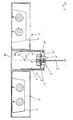
- FIG. 1 shows a cable hanger 1 according to the invention of a preferred embodiment Embodiment with a suspension rope 2, which an a ceiling or the like can be fastened, wherein on the Cable hanger a light housing 3 is suspended, which is a middle equipment carrier 4 and arranged on both sides of this Korpi 5 for receiving bulbs such as of fluorescent tubes or the like with associated reflectors 6 have.
- the luminous center 3a is schematic specified.
- the cable hanger 1 defines a cable support point 7, which through the rope center in the area of the cable attachment is defined.
- the rope attachment takes place here in such a way that at the lamp end facing the cable end a cross-sectional widening is provided in the form of an attached staple 8, wherein the staple completely from the recess 9 of the cable hanger is included, but possibly also partially or completely from the cable hanger in the vertical direction can protrude.
- the luminaire longitudinal direction is in this case by the connecting line the two cable suspensions or their associated Fixing areas defined, which are usually at the end areas of the lamp housing are arranged. It is understood that optionally the width of the wing-like Korpi 5 the length the lamp may exceed or that other irregular Luminaire geometries may be present.
- a lateral Querterrorismsseinschnürung on here as the side open circumferential groove 10 (Fig. 4) is executed. Due to the described below rotation of the cable suspension for Compensation of inclinations of the pendant lamp is understood, that the Querterrorismsseinschnürung at least on through should extend the rotational movement defined peripheral region.
- the circumferential groove 10 engage substantially horizontally arranged mounting portions 11 of the lamp, wherein the attachment areas 11 extend horizontally here and on the lamp are mounted load-bearing.
- the attachment areas 11 are part of a U-profiled support profile 12, but optionally also opposite L-shaped profiles may be provided, wherein the attachment areas 11 having support profile 12 at the same time a displacement assurance of the cable hanger in the longitudinal direction of the luminaire prevented.
- corresponding passage openings in the support profile provided for receiving the cable hanger the can be completely closed.
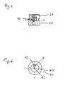
- the center 14 of the attachment area of the cable hanger is here through the center of a Queritesseinschnürung or circumferential groove 10 having Seilauf motivationr Schemes or in the given embodiment by the Defined center of the eccentric, wherein according to the embodiment the attachment portion 11 of the lamp the attachment area 12 of the rope hanger with little play or practical surrounds without play.
- the eccentricity is shown in FIG. 3b indicating the centers of the cable suspension and the center 14 indicated in the attachment area, it is understood that in two rotated by 90 ° to each other positions the lateral displacement the luminaire for cable suspension maximum or minimum is, with a slight shift of rope holding point and center of the attachment area of the cable hanger in the longitudinal direction of the lamp is practically not noticeable.
- the lateral Displacement may be in the range of 1 to 3 mm. Due to the fact that the luminaire is totally against its suspension point is shifted laterally, and thus the luminaire weight Total wear is comparatively low lateral Shifts the lamp sufficiently to this horizontally align.
- the device carrier is with a cover 15 provided by which the cable hanger in vertical Direction protrudes. Due to the lateral displacement of Lamp opposite the cable suspension point has the passage opening 16 of the cover a slightly larger diameter, as the passage opening provided in the attachment area 11, taking into account the diameter of the cable suspension the eccentric movement of the cable suspension relative to be able to compensate for the lamp (see Fig. 5).
- the luminaire according to FIG. 1 represents a double-leafed one Light is, the wings each by one of the two sides the equipment carrier arranged Korpi 5 are formed.
- the Carrier profile 12 is in this case also on the walls 17 of the caste profile 18 load-bearing attached, for example, welded, whereby a high rigidity of the device carrier achieved becomes.
- this has a lower hanger part 20 (see Fig. 2) and an upper hanger part 30 (see Fig. 3).
- the lower hanger part has a holding portion 21 which after the embodiment substantially cylindrical is, and on the web-shaped mounting portion 11 of Light can be applied load-bearing.
- the lower one Hanger part with a contact area for load-bearing Suspension provided on the rope 2, to which the recess 9 is provided is.
- the recess 9 opens into a cable feedthrough 22, with a rope feedthrough 31 to form a Connected rope feedthrough is connected, preferably under coaxial arrangement of the two cable bushings 22, 31.
- the lower suspension part has a fastening means laying down on the upper suspension part, including each other corresponding threaded pin 23 and a threaded recess 32 provided on the upper and lower hanger part are.
- z. B. in the form of a screw lock, be provided as they is known, for. B. by a squeezing element, a bond or the like, always coupled to upper and lower hanger part to be able to move.
- a tool engagement area 24 in the form of opposite ones Flattening to attack an open-end wrench or the like provided to the hanger parts together, preferably non-rotatable to attach.
- the upper hanger part has a tool engagement 33 in the form of a slot which at the same time serves as a marker for the Position of the respective lateral displacement means or the Eccentric 13 is used.
- the upper hanger part a central fastening area in the form of the threaded receptacle 32, which is coaxial with the cable feedthrough 31 or executed a differently designed rope holding area, wherein the eccentric 13 is shifted laterally by about 1 to 3 mm. It is understood that by twisting the wire suspension to 90 ° of the eccentric 13 is also rotated and thereby a lateral Displacement of the lamp housing relative to the cable support point in a direction transverse to the housing longitudinal direction he follows.
- Figure 6 shows an alternative hanger in a schematic Top view, which is essentially like the hanger behind The figures 1-4 is constructed.
Landscapes
- Engineering & Computer Science (AREA)
- General Engineering & Computer Science (AREA)
- Non-Portable Lighting Devices Or Systems Thereof (AREA)
- Securing Globes, Refractors, Reflectors Or The Like (AREA)
- Fastening Of Light Sources Or Lamp Holders (AREA)
- Electric Cable Installation (AREA)
Abstract
Description
- Figur 1
- eine Querschnittsansicht einer Hängeleuchte mit erfindungsgemäßem Seilaufhänger,
- Figur 2
- unter- und oberseitige Draufsichten (Fig. 2a, 2c), Seitenansicht (Fig. 2b), Schnittdarstellung (Fig. 2d) und perspektivische Ansicht (Fig. 2e) eines unteren Aufhängerteils des erfindungsgemäßen Seilaufhängers,
- Figur 3
- unterseitige und oberseitige Draufsichten (Fig. 3a, 3c), Schnittansichten (Fig. 3b, 3d) eines oberen Seilaufhängerteils der erfindungsgemäßen Seilaufhängung,
- Figur 4
- eine Seitenansicht im Teilaufriss eines erfindungsgemäßen Seilaufhängers,
- Figur 5
- eine Draufsicht auf eine Hängeleuchte mit erfindungsgemäßen Seilaufhänger,
- Figur 6
- eine schematische Draufsicht auf einen erfindungsgemäßen Seilaufhänger einer weiteren Ausführungsform,
- 1
- Seilaufhänger
- 2
- Seil
- 3
- Leuchtengehäuse
- 3a
- Leuchtengehäuseschwerpunkt
- 4
- Geräteträger
- 5
- Korpus
- 6
- Reflektor
- 7
- Seilhalterungspunkt
- 8
- Krampe
- 9
- Ausnehmung
- 10
- Umfangsnut
- 11
- Befestigungsbereich
- 12
- Befestigungsbereich
- 12a
- Täger
- 13
- Exzenterelement
- 14
- Zentrum des Befestigungsbereichs
- 15
- Abdeckung
- 16
- Durchtrittsöffnung
- 17
- Wand
- 18
- Kastenprofil
- 20
- unteres Aufhängerteil
- 21
- Haltebereich
- 22
- Seildurchführung
- 23
- Gewindezapfen
- 24
- Werkzeugangriffsbereich
- 30
- oberes Aufhängerteil
- 31
- Seildurchführung
- 32
- Gewindeausnehmung
- 33
- Werkzeugangriffsbereich
- 50
- Schlitz
- 60
- Seilaufhänger
- 61
- Befestigungsbereich
- 62
- Seilhalterungsbereich
- 63
- Drehachse
- 70
- Seilaufhänger
Claims (13)
- Seilaufhänger für Hängeleuchten mit einer Halterung für ein in Einbaulage vertikales Seil zur Aufhängung einer Leuchte in einem Seilhalterungspunkt und mit einem Befestigungsbereich zur Befestigung der Leuchte an dem Aufhänger, wobei der Befestigungsbereich ein Zentrum aufweist, wobei Mittel (13, 71) zur bezogen auf die Seillängserstreckungsrichtung lateralen Verschiebung des Seilhalterungspunktes (7) relativ zum Zentrum (14) des Befestigungsbereichs für die Leuchte oder Mittel (13, 71) zur bezogen auf die Längserstreckung einer zugeordneten Leuchte lateralen Verschiebung des Leuchtenschwerpunktes (3a) relativ zum Seilhalterungspunkt (7) des Leuchtengehäuses vorgesehen sind, dadurch gekennzeichnet, dass das laterale Verschiebungsmittel ein Exzenterelement (13) umfasst, durch dessen Verdrehung eine laterale Verschiebung des Seilhalterungspunktes (7) und des Zentrums (14) des Leuchtenbefestigungsbereichs relativ zueinander oder des Seilhalterungspunktes und des Schwerpunktes (3a) eines zugeordneten Leuchtengehäuses relativ zueinander bewirkt wird.
- Seilaufhänger nach Anspruch 1, dadurch gekennzeichnet, dass die Seilhalterung eine Seildurchführung (22, 31) für das Seil aufweist, die sich durch das Zentrum des Aufhängers (1) erstreckt und bei Betätigung des lateralen Verschiebungsmittels lageunveränderlich ist.
- Seilaufhänger nach Anspruch 1 oder 2, dadurch gekennzeichnet, dass der Seilaufhänger ein in Einbaulage oberes und ein unteres Aufhängerteil (20, 30) umfasst, die aneinander befestigbar sind, und dass zumindest das untere Aufhängerteil (20) eine Seilhalterung (9) und einen Befestigungsbereich (12) für einen korrespondierenden Befestigungsbereich (11) des Leuchtengehäuses aufweist.
- Seilaufhänger nach einem der Ansprüche 1 bis 3, dadurch gekennzeichnet, dass in dem Verbindungsbereich des oberen und unteren Aufhängerteils eine seitliche Querschnittseinschnürung (10) zur Aufnahme eines Befestigungsbereichs des Leuchtengehäuses angeordnet ist.
- Seilaufhänger nach einem der Ansprüche 1 bis 4, dadurch gekennzeichnet, dass das laterale Verschiebungsmittel (13) an dem oberen Aufhängerteil angeordnet ist oder an diesem angreift.
- Seilaufhänger nach Anspruch 5, dadurch gekennzeichnet, dass das laterale Verschiebungsmittel als Exzenterelement (13) ausgeführt ist und an dem oberen Aufhängerteil angeordnet ist.
- Seilaufhänger nach einem der Ansprüche 1 bis 6, dadurch gekennzeichnet, dass ein Betätigungsorgan (30, 33) für die laterale Verschiebung der Seilhalterung relativ zum Befestigungsbereich des Leuchtengehäuses (4) oder für die laterale Verschiebung des Schwerpunktes (3a) der zugeordneten Leuchte zu der Seilhalterung an dem in Einbaulage oberen Ende des Seilaufhängers (1) angeordnet ist.
- Seilaufhänger nach einem der Ansprüche 1 bis 7, dadurch gekennzeichnet, dass ein Betätigungsorgan (33) für das Exzenterelement (13) vorgesehen ist, an dem die Stellung des Exzenterelementes zumindest mittelbar oder unmittelbar ablesbar ist.
- Leuchtengehäuse einer Hängeleuchte mit einer Seilaufhängung mit Mitteln (13, 71) zur bezogen auf die Längserstreckung der Leuchte lateralen Verschiebung des Leuchtengehäuseschwerpunktes (3a) relativ zu zumindest einem oder mehreren Seilhalterungspunkten (7) des Leuchtengehäuses, dadurch gekennzeichnet, dass ein Seilaufhänger nach einem der Ansprüche 1 bis 8 vorgesehen ist.
- Leuchtengehäuse nach Anspruch 9, dadurch gekennzeichnet, dass das Gehäuse einen Befestigungsbereich (11) für den Seilaufhänger (1) aufweist, der in Einbaulage in einer ersten vertikalen Höhe angeordnet ist und dass oberhalb des Befestigungsbereichs eine Abdeckung (15) vorgesehen ist, durch die das laterale Verschiebungsmittel betätigbar ist oder durch die dieses in Einbaulage nach oben oder seitlich aus dem Gehäuse vorsteht.
- Leuchtengehäuse nach Anspruch 9 oder 10, dadurch gekennzeichnet, dass der Seilaufhänger an einem Geräteträger (4) des Leuchtengehäuses befestigt ist.
- Leuchtengehäuse nach einem der Ansprüche 9 bis 11, dadurch gekennzeichnet, dass die Leuchte eine zweiflügelige Leuchte darstellt, bei welcher sich beidseitig der durch die Seilaufhänger definierten Längsachse Korpi (5) zur Aufnahme von Leuchtmitteln erstrecken.
- Leuchtengehäuse nach einem der Ansprüche 9 bis 12, dadurch gekennzeichnet, dass der Befestigungsbereich des Gehäuses als mit zumindest einer Aufnahme für einen Seilaufhänger, vorzugsweise mit zwei in Gehäuselängsrichtung beabstandeten Aufnahmen, versehener Träger (12a) ausgeführt ist, das an der Wandung (17) eines Kastenprofils (18) gehaltert ist, und dass das Kastenprofil eine oberseitige Abdeckung (15) aufweist.
Applications Claiming Priority (2)
| Application Number | Priority Date | Filing Date | Title |
|---|---|---|---|
| DE20307903U DE20307903U1 (de) | 2003-05-19 | 2003-05-19 | Seilaufhängung für Leuchten |
| DE20307903U | 2003-05-19 |
Publications (3)
| Publication Number | Publication Date |
|---|---|
| EP1479969A2 true EP1479969A2 (de) | 2004-11-24 |
| EP1479969A3 EP1479969A3 (de) | 2005-09-14 |
| EP1479969B1 EP1479969B1 (de) | 2010-07-14 |
Family
ID=27771690
Family Applications (1)
| Application Number | Title | Priority Date | Filing Date |
|---|---|---|---|
| EP04011705A Expired - Lifetime EP1479969B1 (de) | 2003-05-19 | 2004-05-17 | Seilaufhänger für Leuchten |
Country Status (4)
| Country | Link |
|---|---|
| US (1) | US7019210B2 (de) |
| EP (1) | EP1479969B1 (de) |
| AT (1) | ATE474188T1 (de) |
| DE (2) | DE20307903U1 (de) |
Cited By (2)
| Publication number | Priority date | Publication date | Assignee | Title |
|---|---|---|---|---|
| EP2107298A1 (de) | 2008-04-03 | 2009-10-07 | Trilux GmbH & Co. KG | Langgestreckte Hängeleuchte |
| AT14426U1 (de) * | 2014-10-07 | 2015-11-15 | Zumtobel Lighting Gmbh | Ausgleichsvorrichtung für eine Seilabhängung einer Leuchte |
Families Citing this family (11)
| Publication number | Priority date | Publication date | Assignee | Title |
|---|---|---|---|---|
| US7086041B2 (en) * | 2003-06-27 | 2006-08-01 | Microsoft Corporation | Extensible type system for representing and checking consistency of program components during the process of compilation |
| FR2977944B1 (fr) * | 2011-07-15 | 2014-02-28 | Senstronic | Dispositif electronique et son procede de fabrication |
| DE102014104421A1 (de) * | 2014-03-28 | 2015-10-15 | Trilux Gmbh & Co. Kg | Variabel umgestaltbare Leuchte |
| US10041660B2 (en) * | 2015-04-06 | 2018-08-07 | Milwaukee Electric Tool Corporation | Hanging light |
| DE102016104428A1 (de) | 2016-03-10 | 2017-09-14 | Trilux Gmbh & Co. Kg | modulare Außenleuchte |
| US10605440B2 (en) | 2017-10-13 | 2020-03-31 | Milwaukee Electric Tool Corporation | Hanging light |
| USD946797S1 (en) | 2017-12-01 | 2022-03-22 | Milwaukee Electric Tool Corporation | Hanging light |
| US11162668B2 (en) | 2018-10-23 | 2021-11-02 | Milwaukee Electric Tool Corporation | Hanging light |
| IT201900007050A1 (it) * | 2019-05-21 | 2020-11-21 | Led Luks D O O | Apparato di illuminazione |
| US11424606B2 (en) * | 2019-06-14 | 2022-08-23 | Biamp Systems, LLC | Electrical device assembly and securing mechanism |
| EP4460659A1 (de) * | 2022-01-04 | 2024-11-13 | Signify Holding B.V. | Einstellbare aufhängbare vorrichtung |
Citations (5)
| Publication number | Priority date | Publication date | Assignee | Title |
|---|---|---|---|---|
| GB624727A (en) | 1946-11-25 | 1949-06-15 | Thorn Electrical Ind Ltd | A device for use in attaching a suspension member to a pendant article |
| US2740883A (en) | 1953-05-11 | 1956-04-03 | A L Smith Iron Company | Combination lighting fixture and wiring conduit |
| WO1980000871A1 (en) | 1978-10-27 | 1980-05-01 | J Hallen | Suspension attachment for elongated armatures |
| DE4010416A1 (de) | 1989-04-05 | 1990-10-11 | Kotzolt Leuchten | Aufhaengevorrichtung |
| US6517222B1 (en) | 2001-08-01 | 2003-02-11 | Linear Lighting Corp. | System and method for leveling suspended lighting fixtures and a longitudunal axis |
Family Cites Families (9)
| Publication number | Priority date | Publication date | Assignee | Title |
|---|---|---|---|---|
| US2465857A (en) * | 1945-11-29 | 1949-03-29 | Separator Ab | Suspension device for flexible pipes and the like |
| DE1828179U (de) | 1960-12-19 | 1961-03-16 | Adolf Schuch K G | Leuchte fuer verschiebbare befestigungsabstaende. |
| DE7838482U1 (de) | 1978-12-27 | 1979-07-12 | Kinkeldey-Leuchten August H. Kinkeldey Bad Pyrmont, 3280 Bad Pyrmont | Rohrfoermiger schirm fuer leuchtstoffroehren, stromschienen o.dgl. |
| DE8622319U1 (de) | 1986-08-20 | 1986-10-30 | Peill + Putzler Glashüttenwerke GmbH, 52349 Düren | Pendelaufhängung für eine Leuchte |
| ZA9610900B (en) | 1995-12-27 | 1997-06-27 | Kevin D Miekis | Supporting structure for a prism light guide |
| CA2321343C (en) | 2000-09-28 | 2008-09-09 | Canlyte Inc. | Linear fixture suspension system |
| TW563954U (en) * | 2002-05-09 | 2003-11-21 | Yue-Yun Huang | Cable storage box with serial connection |
| US6653560B1 (en) * | 2002-07-17 | 2003-11-25 | Wen-Chang Wu | Multi-functional do-it-yourself lamp structure |
| US6870100B2 (en) * | 2002-10-30 | 2005-03-22 | James E. Corwin | Wiring installation device and associated method |
-
2003
- 2003-05-19 DE DE20307903U patent/DE20307903U1/de not_active Expired - Lifetime
-
2004
- 2004-05-17 EP EP04011705A patent/EP1479969B1/de not_active Expired - Lifetime
- 2004-05-17 DE DE502004011382T patent/DE502004011382D1/de not_active Expired - Lifetime
- 2004-05-17 AT AT04011705T patent/ATE474188T1/de active
- 2004-05-18 US US10/847,894 patent/US7019210B2/en not_active Expired - Fee Related
Patent Citations (5)
| Publication number | Priority date | Publication date | Assignee | Title |
|---|---|---|---|---|
| GB624727A (en) | 1946-11-25 | 1949-06-15 | Thorn Electrical Ind Ltd | A device for use in attaching a suspension member to a pendant article |
| US2740883A (en) | 1953-05-11 | 1956-04-03 | A L Smith Iron Company | Combination lighting fixture and wiring conduit |
| WO1980000871A1 (en) | 1978-10-27 | 1980-05-01 | J Hallen | Suspension attachment for elongated armatures |
| DE4010416A1 (de) | 1989-04-05 | 1990-10-11 | Kotzolt Leuchten | Aufhaengevorrichtung |
| US6517222B1 (en) | 2001-08-01 | 2003-02-11 | Linear Lighting Corp. | System and method for leveling suspended lighting fixtures and a longitudunal axis |
Cited By (3)
| Publication number | Priority date | Publication date | Assignee | Title |
|---|---|---|---|---|
| EP2107298A1 (de) | 2008-04-03 | 2009-10-07 | Trilux GmbH & Co. KG | Langgestreckte Hängeleuchte |
| DE102008017462B3 (de) * | 2008-04-03 | 2009-11-26 | Trilux Gmbh & Co. Kg | Langgestreckte Hängeleuchte |
| AT14426U1 (de) * | 2014-10-07 | 2015-11-15 | Zumtobel Lighting Gmbh | Ausgleichsvorrichtung für eine Seilabhängung einer Leuchte |
Also Published As
| Publication number | Publication date |
|---|---|
| DE20307903U1 (de) | 2003-08-21 |
| US7019210B2 (en) | 2006-03-28 |
| EP1479969A3 (de) | 2005-09-14 |
| US20050051673A1 (en) | 2005-03-10 |
| DE502004011382D1 (de) | 2010-08-26 |
| EP1479969B1 (de) | 2010-07-14 |
| ATE474188T1 (de) | 2010-07-15 |
Similar Documents
| Publication | Publication Date | Title |
|---|---|---|
| DE4447144C2 (de) | Trägersystem für elektrische Leitungen | |
| EP1479969A2 (de) | Seilaufhänger für Leuchten | |
| DE202013104140U1 (de) | Einbauleuchte | |
| EP3805576A2 (de) | Kupplung | |
| DE4332437C2 (de) | Tisch und Tischsystem | |
| EP3461963B1 (de) | Trägersystem und system von verbindungselementen zur verbindung von trägern | |
| EP2107298B1 (de) | Langgestreckte Hängeleuchte | |
| EP3922869B1 (de) | Anschlussvorrichtung zum befestigen an einem hohlprofil sowie stabilisierungsset und stabilisierungsanordnung | |
| DE4116210A1 (de) | Befestigungssystem fuer lichtschrankenelemente | |
| EP2383511B1 (de) | Anordnung zur Befestigung eines Gegenstandes an einem langgestreckten Aufhängungselement | |
| DE20319586U1 (de) | Tragschiene für Leuchtkörper | |
| EP0931977B1 (de) | Vorrichtung zum Befestigen von Leuchten an Masten | |
| DE3710609A1 (de) | Aufhaengevorrichtung fuer haengeleuchten | |
| EP1351025B1 (de) | Wandhalter für Heizkörper | |
| DE10036157A1 (de) | Vorrichtung zum Stützen von Fassadenelementen | |
| DE29901397U1 (de) | Längliche, im Querschnittsprofil linsenartige Pendel- oder Anbauleuchte | |
| DE3824596A1 (de) | Leuchte, insbesondere rohrfoermige leuchte fuer leuchtstofflampen | |
| EP3056798B1 (de) | Einbauelement, vorzugsweise einbauleuchte | |
| DE4114378C2 (de) | ||
| DE2232970C2 (de) | Endklammer zur Sicherung von KLemmenblöcken auf einer Schiene | |
| DE4010416A1 (de) | Aufhaengevorrichtung | |
| DE2844600C3 (de) | Deckeneinbauleuchte | |
| AT14426U1 (de) | Ausgleichsvorrichtung für eine Seilabhängung einer Leuchte | |
| AT14937U1 (de) | Seilabhängungsvorrichtung | |
| DE19713818A1 (de) | Adapter für ein Haltemittel, welches zum Befestigen einer Einbauleuchte in einer Einbauöffnung bestimmt ist, oder Haltemittel oder Einbauleuchte mit einem solchen Adapter |
Legal Events
| Date | Code | Title | Description |
|---|---|---|---|
| PUAI | Public reference made under article 153(3) epc to a published international application that has entered the european phase |
Free format text: ORIGINAL CODE: 0009012 |
|
| AK | Designated contracting states |
Kind code of ref document: A2 Designated state(s): AT BE BG CH CY CZ DE DK EE ES FI FR GB GR HU IE IT LI LU MC NL PL PT RO SE SI SK TR |
|
| AX | Request for extension of the european patent |
Extension state: AL HR LT LV MK |
|
| PUAL | Search report despatched |
Free format text: ORIGINAL CODE: 0009013 |
|
| AK | Designated contracting states |
Kind code of ref document: A3 Designated state(s): AT BE BG CH CY CZ DE DK EE ES FI FR GB GR HU IE IT LI LU MC NL PL PT RO SE SI SK TR |
|
| AX | Request for extension of the european patent |
Extension state: AL HR LT LV MK |
|
| RIC1 | Information provided on ipc code assigned before grant |
Ipc: 7F 21V 21/008 B Ipc: 7F 21S 8/06 B Ipc: 7F 21V 21/112 A Ipc: 7F 21V 21/00 B |
|
| 17P | Request for examination filed |
Effective date: 20051214 |
|
| AKX | Designation fees paid |
Designated state(s): AT BE BG CH CY CZ DE DK EE ES FI FR GB GR HU IE IT LI LU MC NL PL PT RO SE SI SK TR |
|
| 17Q | First examination report despatched |
Effective date: 20070518 |
|
| RAP1 | Party data changed (applicant data changed or rights of an application transferred) |
Owner name: TRILUX GMBH & CO. KG |
|
| GRAP | Despatch of communication of intention to grant a patent |
Free format text: ORIGINAL CODE: EPIDOSNIGR1 |
|
| GRAS | Grant fee paid |
Free format text: ORIGINAL CODE: EPIDOSNIGR3 |
|
| GRAA | (expected) grant |
Free format text: ORIGINAL CODE: 0009210 |
|
| AK | Designated contracting states |
Kind code of ref document: B1 Designated state(s): AT BE BG CH CY CZ DE DK EE ES FI FR GB GR HU IE IT LI LU MC NL PL PT RO SE SI SK TR |
|
| REG | Reference to a national code |
Ref country code: GB Ref legal event code: FG4D Free format text: NOT ENGLISH |
|
| REG | Reference to a national code |
Ref country code: CH Ref legal event code: EP |
|
| REG | Reference to a national code |
Ref country code: IE Ref legal event code: FG4D |
|
| REF | Corresponds to: |
Ref document number: 502004011382 Country of ref document: DE Date of ref document: 20100826 Kind code of ref document: P |
|
| REG | Reference to a national code |
Ref country code: NL Ref legal event code: VDEP Effective date: 20100714 |
|
| PG25 | Lapsed in a contracting state [announced via postgrant information from national office to epo] |
Ref country code: FI Free format text: LAPSE BECAUSE OF FAILURE TO SUBMIT A TRANSLATION OF THE DESCRIPTION OR TO PAY THE FEE WITHIN THE PRESCRIBED TIME-LIMIT Effective date: 20100714 Ref country code: NL Free format text: LAPSE BECAUSE OF FAILURE TO SUBMIT A TRANSLATION OF THE DESCRIPTION OR TO PAY THE FEE WITHIN THE PRESCRIBED TIME-LIMIT Effective date: 20100714 |
|
| REG | Reference to a national code |
Ref country code: IE Ref legal event code: FD4D |
|
| PG25 | Lapsed in a contracting state [announced via postgrant information from national office to epo] |
Ref country code: PT Free format text: LAPSE BECAUSE OF FAILURE TO SUBMIT A TRANSLATION OF THE DESCRIPTION OR TO PAY THE FEE WITHIN THE PRESCRIBED TIME-LIMIT Effective date: 20101115 Ref country code: SI Free format text: LAPSE BECAUSE OF FAILURE TO SUBMIT A TRANSLATION OF THE DESCRIPTION OR TO PAY THE FEE WITHIN THE PRESCRIBED TIME-LIMIT Effective date: 20100714 Ref country code: BG Free format text: LAPSE BECAUSE OF FAILURE TO SUBMIT A TRANSLATION OF THE DESCRIPTION OR TO PAY THE FEE WITHIN THE PRESCRIBED TIME-LIMIT Effective date: 20101014 Ref country code: CY Free format text: LAPSE BECAUSE OF FAILURE TO SUBMIT A TRANSLATION OF THE DESCRIPTION OR TO PAY THE FEE WITHIN THE PRESCRIBED TIME-LIMIT Effective date: 20100714 Ref country code: PL Free format text: LAPSE BECAUSE OF FAILURE TO SUBMIT A TRANSLATION OF THE DESCRIPTION OR TO PAY THE FEE WITHIN THE PRESCRIBED TIME-LIMIT Effective date: 20100714 |
|
| PG25 | Lapsed in a contracting state [announced via postgrant information from national office to epo] |
Ref country code: GR Free format text: LAPSE BECAUSE OF FAILURE TO SUBMIT A TRANSLATION OF THE DESCRIPTION OR TO PAY THE FEE WITHIN THE PRESCRIBED TIME-LIMIT Effective date: 20101015 Ref country code: SE Free format text: LAPSE BECAUSE OF FAILURE TO SUBMIT A TRANSLATION OF THE DESCRIPTION OR TO PAY THE FEE WITHIN THE PRESCRIBED TIME-LIMIT Effective date: 20100714 |
|
| PG25 | Lapsed in a contracting state [announced via postgrant information from national office to epo] |
Ref country code: DK Free format text: LAPSE BECAUSE OF FAILURE TO SUBMIT A TRANSLATION OF THE DESCRIPTION OR TO PAY THE FEE WITHIN THE PRESCRIBED TIME-LIMIT Effective date: 20100714 Ref country code: IE Free format text: LAPSE BECAUSE OF FAILURE TO SUBMIT A TRANSLATION OF THE DESCRIPTION OR TO PAY THE FEE WITHIN THE PRESCRIBED TIME-LIMIT Effective date: 20100714 |
|
| PLBE | No opposition filed within time limit |
Free format text: ORIGINAL CODE: 0009261 |
|
| STAA | Information on the status of an ep patent application or granted ep patent |
Free format text: STATUS: NO OPPOSITION FILED WITHIN TIME LIMIT |
|
| PG25 | Lapsed in a contracting state [announced via postgrant information from national office to epo] |
Ref country code: IT Free format text: LAPSE BECAUSE OF FAILURE TO SUBMIT A TRANSLATION OF THE DESCRIPTION OR TO PAY THE FEE WITHIN THE PRESCRIBED TIME-LIMIT Effective date: 20100714 Ref country code: EE Free format text: LAPSE BECAUSE OF FAILURE TO SUBMIT A TRANSLATION OF THE DESCRIPTION OR TO PAY THE FEE WITHIN THE PRESCRIBED TIME-LIMIT Effective date: 20100714 Ref country code: SK Free format text: LAPSE BECAUSE OF FAILURE TO SUBMIT A TRANSLATION OF THE DESCRIPTION OR TO PAY THE FEE WITHIN THE PRESCRIBED TIME-LIMIT Effective date: 20100714 Ref country code: RO Free format text: LAPSE BECAUSE OF FAILURE TO SUBMIT A TRANSLATION OF THE DESCRIPTION OR TO PAY THE FEE WITHIN THE PRESCRIBED TIME-LIMIT Effective date: 20100714 Ref country code: CZ Free format text: LAPSE BECAUSE OF FAILURE TO SUBMIT A TRANSLATION OF THE DESCRIPTION OR TO PAY THE FEE WITHIN THE PRESCRIBED TIME-LIMIT Effective date: 20100714 |
|
| 26N | No opposition filed |
Effective date: 20110415 |
|
| PG25 | Lapsed in a contracting state [announced via postgrant information from national office to epo] |
Ref country code: ES Free format text: LAPSE BECAUSE OF FAILURE TO SUBMIT A TRANSLATION OF THE DESCRIPTION OR TO PAY THE FEE WITHIN THE PRESCRIBED TIME-LIMIT Effective date: 20101025 |
|
| REG | Reference to a national code |
Ref country code: DE Ref legal event code: R097 Ref document number: 502004011382 Country of ref document: DE Effective date: 20110415 |
|
| BERE | Be: lapsed |
Owner name: TRILUX G.M.B.H. & CO. KG Effective date: 20110531 |
|
| PG25 | Lapsed in a contracting state [announced via postgrant information from national office to epo] |
Ref country code: MC Free format text: LAPSE BECAUSE OF NON-PAYMENT OF DUE FEES Effective date: 20110531 |
|
| REG | Reference to a national code |
Ref country code: CH Ref legal event code: PL |
|
| GBPC | Gb: european patent ceased through non-payment of renewal fee |
Effective date: 20110517 |
|
| PG25 | Lapsed in a contracting state [announced via postgrant information from national office to epo] |
Ref country code: LI Free format text: LAPSE BECAUSE OF NON-PAYMENT OF DUE FEES Effective date: 20110531 Ref country code: CH Free format text: LAPSE BECAUSE OF NON-PAYMENT OF DUE FEES Effective date: 20110531 |
|
| REG | Reference to a national code |
Ref country code: FR Ref legal event code: ST Effective date: 20120131 |
|
| PG25 | Lapsed in a contracting state [announced via postgrant information from national office to epo] |
Ref country code: BE Free format text: LAPSE BECAUSE OF NON-PAYMENT OF DUE FEES Effective date: 20110531 |
|
| PG25 | Lapsed in a contracting state [announced via postgrant information from national office to epo] |
Ref country code: FR Free format text: LAPSE BECAUSE OF NON-PAYMENT OF DUE FEES Effective date: 20110531 |
|
| PG25 | Lapsed in a contracting state [announced via postgrant information from national office to epo] |
Ref country code: GB Free format text: LAPSE BECAUSE OF NON-PAYMENT OF DUE FEES Effective date: 20110517 |
|
| REG | Reference to a national code |
Ref country code: AT Ref legal event code: MM01 Ref document number: 474188 Country of ref document: AT Kind code of ref document: T Effective date: 20110517 |
|
| PG25 | Lapsed in a contracting state [announced via postgrant information from national office to epo] |
Ref country code: AT Free format text: LAPSE BECAUSE OF NON-PAYMENT OF DUE FEES Effective date: 20110517 |
|
| PG25 | Lapsed in a contracting state [announced via postgrant information from national office to epo] |
Ref country code: LU Free format text: LAPSE BECAUSE OF NON-PAYMENT OF DUE FEES Effective date: 20110517 |
|
| PG25 | Lapsed in a contracting state [announced via postgrant information from national office to epo] |
Ref country code: TR Free format text: LAPSE BECAUSE OF FAILURE TO SUBMIT A TRANSLATION OF THE DESCRIPTION OR TO PAY THE FEE WITHIN THE PRESCRIBED TIME-LIMIT Effective date: 20100714 |
|
| PG25 | Lapsed in a contracting state [announced via postgrant information from national office to epo] |
Ref country code: HU Free format text: LAPSE BECAUSE OF FAILURE TO SUBMIT A TRANSLATION OF THE DESCRIPTION OR TO PAY THE FEE WITHIN THE PRESCRIBED TIME-LIMIT Effective date: 20100714 |
|
| PGFP | Annual fee paid to national office [announced via postgrant information from national office to epo] |
Ref country code: DE Payment date: 20210728 Year of fee payment: 18 |
|
| REG | Reference to a national code |
Ref country code: DE Ref legal event code: R119 Ref document number: 502004011382 Country of ref document: DE |
|
| PG25 | Lapsed in a contracting state [announced via postgrant information from national office to epo] |
Ref country code: DE Free format text: LAPSE BECAUSE OF NON-PAYMENT OF DUE FEES Effective date: 20221201 |