EP1477765A1 - Verfahren zum erkennen eines erkennungsobjekts und einrichtung dafür; verfahren zum untersuchen eines untersuchungsobjekts und einrichtung dafür - Google Patents
Verfahren zum erkennen eines erkennungsobjekts und einrichtung dafür; verfahren zum untersuchen eines untersuchungsobjekts und einrichtung dafür Download PDFInfo
- Publication number
- EP1477765A1 EP1477765A1 EP03706990A EP03706990A EP1477765A1 EP 1477765 A1 EP1477765 A1 EP 1477765A1 EP 03706990 A EP03706990 A EP 03706990A EP 03706990 A EP03706990 A EP 03706990A EP 1477765 A1 EP1477765 A1 EP 1477765A1
- Authority
- EP
- European Patent Office
- Prior art keywords
- workpiece
- data
- shape
- tire
- appearance
- Prior art date
- Legal status (The legal status is an assumption and is not a legal conclusion. Google has not performed a legal analysis and makes no representation as to the accuracy of the status listed.)
- Granted
Links
- 238000000034 method Methods 0.000 title claims description 30
- 238000001514 detection method Methods 0.000 title claims description 9
- 238000007689 inspection Methods 0.000 title description 9
- 238000003384 imaging method Methods 0.000 claims abstract description 25
- 238000010586 diagram Methods 0.000 description 6
- 238000002845 discoloration Methods 0.000 description 6
- 230000005484 gravity Effects 0.000 description 3
- 239000003086 colorant Substances 0.000 description 1
- 230000007547 defect Effects 0.000 description 1
- 238000006073 displacement reaction Methods 0.000 description 1
- 229910052736 halogen Inorganic materials 0.000 description 1
- 150000002367 halogens Chemical class 0.000 description 1
- 238000005259 measurement Methods 0.000 description 1
- 230000002093 peripheral effect Effects 0.000 description 1
- 239000004065 semiconductor Substances 0.000 description 1
- 238000004073 vulcanization Methods 0.000 description 1
Images


Classifications
-
- G—PHYSICS
- G01—MEASURING; TESTING
- G01N—INVESTIGATING OR ANALYSING MATERIALS BY DETERMINING THEIR CHEMICAL OR PHYSICAL PROPERTIES
- G01N21/00—Investigating or analysing materials by the use of optical means, i.e. using sub-millimetre waves, infrared, visible or ultraviolet light
- G01N21/84—Systems specially adapted for particular applications
- G01N21/88—Investigating the presence of flaws or contamination
- G01N21/95—Investigating the presence of flaws or contamination characterised by the material or shape of the object to be examined
-
- G—PHYSICS
- G01—MEASURING; TESTING
- G01B—MEASURING LENGTH, THICKNESS OR SIMILAR LINEAR DIMENSIONS; MEASURING ANGLES; MEASURING AREAS; MEASURING IRREGULARITIES OF SURFACES OR CONTOURS
- G01B11/00—Measuring arrangements characterised by the use of optical techniques
- G01B11/24—Measuring arrangements characterised by the use of optical techniques for measuring contours or curvatures
- G01B11/25—Measuring arrangements characterised by the use of optical techniques for measuring contours or curvatures by projecting a pattern, e.g. one or more lines, moiré fringes on the object
- G01B11/2518—Projection by scanning of the object
- G01B11/2522—Projection by scanning of the object the position of the object changing and being recorded
-
- G—PHYSICS
- G01—MEASURING; TESTING
- G01M—TESTING STATIC OR DYNAMIC BALANCE OF MACHINES OR STRUCTURES; TESTING OF STRUCTURES OR APPARATUS, NOT OTHERWISE PROVIDED FOR
- G01M17/00—Testing of vehicles
- G01M17/007—Wheeled or endless-tracked vehicles
- G01M17/02—Tyres
- G01M17/027—Tyres using light, e.g. infrared, ultraviolet or holographic techniques
-
- G—PHYSICS
- G01—MEASURING; TESTING
- G01N—INVESTIGATING OR ANALYSING MATERIALS BY DETERMINING THEIR CHEMICAL OR PHYSICAL PROPERTIES
- G01N21/00—Investigating or analysing materials by the use of optical means, i.e. using sub-millimetre waves, infrared, visible or ultraviolet light
- G01N21/84—Systems specially adapted for particular applications
- G01N21/88—Investigating the presence of flaws or contamination
- G01N21/8851—Scan or image signal processing specially adapted therefor, e.g. for scan signal adjustment, for detecting different kinds of defects, for compensating for structures, markings, edges
-
- G—PHYSICS
- G06—COMPUTING; CALCULATING OR COUNTING
- G06T—IMAGE DATA PROCESSING OR GENERATION, IN GENERAL
- G06T7/00—Image analysis
- G06T7/50—Depth or shape recovery
- G06T7/521—Depth or shape recovery from laser ranging, e.g. using interferometry; from the projection of structured light
Definitions
- the present invention relates to a method and apparatus for detecting or inspecting the appearance and shape of a workpiece such as a tire or tire part by imaging it.
- a product is imaged by a line camera to judge whether the surface state such as discoloration or stains of the workpiece is acceptable or not from the obtained appearance data.
- discoloration or stains can be judged accurately from data on the appearance imaged by the line camera but the shape of the workpiece cannot be judged accurately. Therefore, a light-section method in which the surface of the workpiece is imaged by an area camera by applying slit light to detect the shape of the workpiece from the obtained image data is employed.
- JP-A 11-138654 To inspect the shape of a tire by the above light-section method, as disclosed by JP-A 11-138654 (the term "JP-A" as used herein means an "unexamined published Japanese patent application"), for example, slit light is applied to the surface of the tire by floodlight means such as a semiconductor laser to image a portion illuminated by the above slit light with an area camera, the obtained image data is converted into secondary coordinate values to obtain the outer shape of the tire, and the shape is compared with the pre-stored image of the workpiece to inspect the shape of the tire such as a beat, tread or side wall portion. At this point, the shape and circularity of the tire in a predetermined region can be detected and inspected by turning the floodlight means, the imaging means and the tire relative to one another.
- floodlight means such as a semiconductor laser to image a portion illuminated by the above slit light with an area camera
- the obtained image data is converted into secondary coordinate values to obtain the outer shape of the tire
- imaging means 50 which comprises a floodlight (illuminator) 51 making use of a white LED, line camera 52, line reflection mirror 53, laser floodlight 54 having a wavelength of 680 nm and area camera 55, all built in one holding frame 56, to pick up a slit image of the tire T illuminated by light from the above floodlight 51 with the line camera 52 so as to obtain monochromatic or color appearance data and to input shape data on a ridge line on the surface of the tire T obtained by imaging a portion illuminated by slit light from the laser floodlight 54 with the area camera 55.
- floodlight illumination
- line camera 52 line reflection mirror 53
- laser floodlight 54 having a wavelength of 680 nm and area camera 55
- the above obtained appearance data and shape data are transmitted to the appearance image forming means 61 and shape image forming means 62 of an appearance and shape judging unit 60 to be processed, compared with tire appearance and shape data pre-stored in tire information storage means 65 to judge whether the appearance and shape are acceptable or not, and finally whether the tire is acceptable or not is judged by overall judging means 66.
- the apparatus becomes bulky and it is difficult to optically align a line portion to be imaged by the line camera 52 with a line portion to be imaged by the area camera 55.
- data processing becomes complicated and storage means or computing means for processing data is necessary.
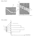
- the inventors of the present invention paid attention to the fact that when a portion having a color different from the color of the base of a tire, such as a stain or discoloration, is included in an illuminated portion, light applied to the tire T has a wide wavelength distribution, the line width of the above slit image "S" becomes nonuniform, and the brightness of each pixel "s" becomes different as shown in Fig. 2 (b) and found that the appearance and shape of the workpiece can be detected from one slit image "S" at the same time by obtaining the density (or color) of the workpiece from data on the brightness of each pixel "s".
- the present invention has been accomplished based on this finding.
- a method of detecting the coordinates and brightness of a workpiece comprising the steps of:
- a method of inspecting a workpiece comprising the steps of:
- a method of inspecting a workpiece wherein the coordinates and brightness of a specific region of the workpiece are integrated to obtain the shape data and density data of the specific region.
- a method of inspecting a workpiece wherein the obtained shape data or density data is compared with the reference shape data or reference density data on the specific region of the workpiece to inspect the workpiece.
- a method of inspecting a workpiece wherein it is judged that the specific region of the workpiece is unacceptable when the size of a region in which the difference between the obtained shape data and reference shape data and/or the difference between the obtained density data and reference density data exceeds a preset threshold value becomes larger than a predetermined value.
- a method of inspecting a workpiece wherein the workpiece is inspected based on surface unevenness calculated from the obtained shape data or the degree of density calculated from the obtained density data.
- a seventh aspect of the present invention there is provided a method of inspecting a workpiece, wherein three white slit beams and a color camera are used to detect the shape and color of the workpiece at the same time.
- an apparatus for detecting the appearance and shape of a workpiece by detecting the coordinates and brightness of the workpiece comprising:
- an apparatus for detecting a workpiece wherein white light is used as the slit light and a color camera is used as the imaging means.
- an apparatus for inspecting a workpiece comprising:
- Fig. 1 is a diagram showing the constitution of a tire appearance and shape inspection apparatus according to a preferred embodiment of the present invention.
- reference numeral 10 denotes floodlight means for applying white slit light to the surface to be inspected of a tire T as a workpiece mounted on a rotary table 2 turned by a motor 1, 20 a color CCD camera, having pixels on a plane, for imaging a portion L illuminated by the above slit light of the turning tire T, 30 a tire judging unit for judging whether the shape and appearance of the above tire are acceptable or not by detecting the shape and appearance of the tire T from an image obtained by the color CCD camera 20, 3 motor drive and control means for driving and controlling the above motor 1, and 4 rotation angle detection means for detecting the rotation angle ⁇ of the tire T by detecting the rotation position of the above rotary table 2.
- the tire judging unit 30 comprises coordinate computing means 31 for obtaining data on the 3-D coordinates of the tire T from an image (slit image "S") of a ridge line on the surface of the tire T imaged by the color CCD camera 20 and the rotation angle ⁇ of the tire T detected by the rotation angle detection means 4, shape image forming means 32 for re-forming a 3-D image of the tire T by collecting the above 3-D coordinate data of one round of the tire, brightness computing means 33 for computing brightness data on R, G and B computed from the above slit image "S", appearance image forming means 34 for re-forming a color image of the tire T from the above brightness data and 3-D coordinate data, shape judging means 36 and appearance judging means 37 for comparing the obtained 3-D image and color image of the tire T with the above reference data, and overall judging means 38 for judging whether the tire T is acceptable or not.
- coordinate computing means 31 for obtaining data on the 3-D coordinates of the tire T from an image (slit image "S") of a ridge line on the
- the motor 1 is first driven by the motor drive and control means 3 to turn the rotary table 2 mounting the tire T to be inspected, white slit light is applied to the above turning tire T from the floodlight means 10 comprising a white light source such as a white laser or halogen lamp to image the illuminated portion L of the tire T with the color CCD camera 20 so as to obtain image data (slit image "S") on the ridge line on the surface of the tire T, and the image data is sent to the coordinate computing means 31 of the tire judging unit 30.
- a white light source such as a white laser or halogen lamp
- the coordinate computing means 31 computes the positions of the gravity centers of illuminated pixels "s", out of the plurality of pixels forming the above slit image "S", to obtain the 2-D coordinates (x, z) of each position of the above slit image "S", and the 3-D coordinate data (x, y, z) of the tire T are obtained from the 2-D coordinates (x, z) and the rotation angle ⁇ of the tire T detected by the above rotation angle detection means 4.
- the shape image forming means 32 computes the above 3-D coordinate data (3-D shape data) of one round of the tire by collecting the slit image "S" for each ⁇ to detect the coordinates of the tire T as the workpiece and process the 3-D data to re-form a 3-D image of the tire T.
- the brightness computing means 33 integrates the brightness's of the pixels "s" used for the computation of the above positions of the gravity centers to detect the brightness of the tire T as the workpiece so as to obtain brightness data at the above 3-D coordinate position (x, Y, z).
- the appearance image forming means 34 processes an image by using the above 3-D coordinate brightness data and the 3-D coordinate data (x, y, z) of the tire T to re-form a color image or shaded image of the tire T.
- the 3-D image and color image or shaded image of the tire T which have been processed are compared with tire appearance and shape data pre-stored in the tire information storage means 35 by the shape judging means 36 and the appearance judging means 37 respectively to judge whether the circularity, surface unevenness and scratch, or appearance such as discoloration or stains and shape of the tire are acceptable or not, and the overall judging means 38 finally judges whether the tire is acceptable or not to inspect the tire T as the workpiece.
- the 3-D data or 3-D image of the above tire T For the actual inspection of the appearance and shape of the tire, it is not necessary to form the 3-D data or 3-D image of the above tire T and compare all of it with the reference data. For instance, the coordinates and brightness of a specific region such as an inner side portion or inner crown portion are estimated to compute the shape data of the specific region, and the 3-D shape data or 3-D image of the specific region is compared with the tire shape data of the above specific region pre-stored in the tire information storage means 35 to inspect the shape of the above tire T. That is, since shape and size reference values can be set by comparison for each specific region, whether the workpiece is acceptable or not can be judged more easily.
- the shape of the tire T may be inspected by comparing surface unevenness calculated from the above obtained shape data with the previously set threshold value (reference shape data) instead of comparison with data on the shape of the above tire. Alternatively, whether the shape of the tire is acceptable or not may be judged based on surface unevenness observed from a 3-D image of the tire T.
- the degree of density calculated from density data may be compared with the preset threshold value (reference density data) to inspect the appearance of the above tire T or to judge whether the appearance of the tire is acceptable or not based on the degree of density observed from a color image (or shaded image) of the above tire T in place of comparison with data on the appearance of the above tire.
- a specific region is unacceptable when the size of the region in which the difference between the above obtained 3-D shape data and the above tire shape data and/or the difference between the obtained 3-D density data and the above tire appearance data exceed(s) the preset threshold value becomes larger than a predetermined value.
- an inner shoulder portion or inner side portion when a portion having a height larger than a predetermined value exists over a predetermined length or more in a peripheral direction, it is considered that the inner shoulder portion or the inner side portion is unacceptable.
- appearance inspection it is judged that the appearance of the above side portion is unacceptable when a region having a brightness outside a predetermined range considered as a defect has a predetermined area or more in the side portion.
- the tire mounted on the rotary table 2 is imaged by the floodlight means 10 for applying white slit light and the color CCD camera 20 for imaging a portion illuminated by the above slit light while the tire T is turned, and the coordinates and brightness of the above tire T are calculated from the above obtained image data by the coordinate computing means 31 and the brightness computing means 33 to detect the shape and color of the above tire T. Therefore, the shape and appearance of the tire T can be inspected at the same time with a simple structure.
- the workpiece is a product tire T.
- the present invention is not limited to this workpiece and may be a tire or tire constituting member before vulcanization, mechanical part or golf head whose appearance and shape must be inspected.
- the color CCD camera 20 is used to obtain a color image of the tire T.
- an appearance image is a monochromatic image and not satisfactory
- one-color slit light and a monochromatic CCD camera may be used to obtain a shaded image of the tire T.
- a white laser does not need to be used as a light source.
- slit beams may be applied to the tire T from R, G and B one-color lasers as light sources at predetermined intervals to take a color image with monochromatic CCD cameras.
- three lines (monochromatic images) A, B and C which are shifted from one another by the above time interval are obtained as slit images as shown in Fig. 3.
- a color image of the tire T can be obtained without using the color CCD camera 20.
- a one-color laser (R) and G and B one-color LED's as light sources may be used to take a color image with the color CCD camera 20.
- a slit image P obtained with the one-color laser and a line Q obtained with the one-color LED's adjacent to the above slit image are obtained as shown in Fig. 4.
- a workpiece, floodlight means for applying slit light to the surface to be inspected of the workpiece, and imaging means having an area camera for imaging a portion illuminated by the slit light are moved relative to one another to image the above workpiece, and the coordinates and brightness of the workpiece are calculated from the pixel data of the area camera to detect the shape and density (or color) of the workpiece and to inspect the shape and appearance of the above workpiece at the same time. Therefore, the shape and appearance of the tire T can be inspected accurately at the same time with a simple structure.
Applications Claiming Priority (3)
| Application Number | Priority Date | Filing Date | Title |
|---|---|---|---|
| JP2002044449 | 2002-02-21 | ||
| JP2002044449A JP2003240521A (ja) | 2002-02-21 | 2002-02-21 | 被検体の外観・形状検査方法とその装置、及び、被検体の外観・形状検出装置 |
| PCT/JP2003/001915 WO2003071224A1 (fr) | 2002-02-21 | 2003-02-21 | Procede et dispositif de detection d'un objet, procede et dispositif d'examen d'un objet |
Publications (3)
| Publication Number | Publication Date |
|---|---|
| EP1477765A1 true EP1477765A1 (de) | 2004-11-17 |
| EP1477765A4 EP1477765A4 (de) | 2009-12-09 |
| EP1477765B1 EP1477765B1 (de) | 2016-05-18 |
Family
ID=27750549
Family Applications (1)
| Application Number | Title | Priority Date | Filing Date |
|---|---|---|---|
| EP03706990.3A Expired - Fee Related EP1477765B1 (de) | 2002-02-21 | 2003-02-21 | Verfahren zum erkennen eines erkennungsobjekts und einrichtung dafür; verfahren zum untersuchen eines untersuchungsobjekts und einrichtung dafür |
Country Status (4)
| Country | Link |
|---|---|
| US (1) | US7421108B2 (de) |
| EP (1) | EP1477765B1 (de) |
| JP (1) | JP2003240521A (de) |
| WO (1) | WO2003071224A1 (de) |
Cited By (16)
| Publication number | Priority date | Publication date | Assignee | Title |
|---|---|---|---|---|
| EP1757902A1 (de) * | 2005-08-24 | 2007-02-28 | DeguDent GmbH | Verfahren und Vorrichtung zur Formerfassung eines zahntechnischen Objektes |
| EP1792685A2 (de) | 2005-12-02 | 2007-06-06 | The Goodyear Tire & Rubber Company | Verfahren und Vorrichtung zur Identifizierung der dreidimensionalen Koordinaten eines Reifens |
| DE102006014070A1 (de) * | 2006-03-27 | 2007-10-11 | Mähner, Bernward | Vorrichtung und Verfahren zum Prüfen eines Reifens, insbesondere mittels eines interferometrischen Messverfahrens |
| DE102006015123A1 (de) * | 2006-03-31 | 2007-10-18 | Mähner, Bernward | Vorrichtung und Verfahren zum Prüfen eines Reifens, insbesondere mittels eines interferometrischen Messverfahrens |
| EP2023078A1 (de) * | 2007-08-06 | 2009-02-11 | Kabushiki Kaisha Kobe Seiko Sho | Reifenform-Messsystem |
| WO2009077537A1 (fr) * | 2007-12-19 | 2009-06-25 | Societe De Technologie Michelin | Methode d'evaluation par comparaison d'une image acquise avec une image de reference |
| WO2009077539A2 (fr) * | 2007-12-19 | 2009-06-25 | Societe De Technologie Michelin | Methode de traitement d'une image tri dimensionnelle de la surface d'un pneumatique en vue de son utilisation pour l'inspection de ladite surface |
| EP2078955A1 (de) * | 2006-11-02 | 2009-07-15 | Bridgestone Corporation | Verfahren und vorrichtung zur inspektion einer reifenoberfläche |
| ITTO20101071A1 (it) * | 2010-12-27 | 2012-06-28 | Bridgestone Corp | Metodo e stazione di misura per rilevare le coordinate di una superficie di un pneumatico sotto carico |
| CN103168220A (zh) * | 2010-10-19 | 2013-06-19 | 米其林企业总公司 | 用于识别和定义形成轮胎胎面设计的基本花纹的方法 |
| CN103477183A (zh) * | 2011-04-20 | 2013-12-25 | 株式会社神户制钢所 | 轮胎表面形状测定装置及轮胎表面形状测定方法 |
| EP2322899A4 (de) * | 2008-08-26 | 2015-10-28 | Bridgestone Corp | Verfahren zur erkennung der rauheit einer probe und vorrichtung zur durchführung dieses verfahrens |
| CN105190277A (zh) * | 2012-12-21 | 2015-12-23 | 倍耐力轮胎股份公司 | 在生产线中控制轮胎或相关半成品的方法和装置 |
| WO2016103131A1 (en) * | 2014-12-22 | 2016-06-30 | Pirelli Tyre | Method and apparatus for detecting defects on tyres in a tyre production process |
| CN106104201A (zh) * | 2014-04-07 | 2016-11-09 | 横滨橡胶株式会社 | 轮胎模具的刻印检查方法及装置 |
| WO2020169833A1 (fr) * | 2019-02-22 | 2020-08-27 | Safran Electronics & Defense | Procede de detection d'une degradation d'un pneumatique d'une roue |
Families Citing this family (48)
| Publication number | Priority date | Publication date | Assignee | Title |
|---|---|---|---|---|
| JP4419481B2 (ja) * | 2003-09-03 | 2010-02-24 | 横浜ゴム株式会社 | タイヤ形状の測定方法及びその装置 |
| JP4679073B2 (ja) * | 2004-05-18 | 2011-04-27 | 株式会社ブリヂストン | タイヤ凹凸図形の検査方法、および、タイヤ凹凸図形検査装置 |
| BRPI0518033B1 (pt) * | 2004-11-22 | 2017-07-04 | Bridgestone Corporation | Apparatus for inspection of external appearance |
| CA2556533A1 (en) * | 2005-08-24 | 2007-02-24 | Degudent Gmbh | Method of determining the shape of a dental technology object and apparatus performing the method |
| US20070177788A1 (en) * | 2006-01-31 | 2007-08-02 | David Liu | System and method for detecting wafer failure in wet bench applications |
| DE502006009454D1 (de) * | 2006-03-23 | 2011-06-16 | Bernward Maehner | Ewegender objekte |
| DE102006014058B4 (de) * | 2006-03-27 | 2008-04-17 | Mähner, Bernward | Vorrichtung und Verfahren zum optischen Prüfen eines Reifens |
| JP4977415B2 (ja) | 2006-07-21 | 2012-07-18 | 株式会社ブリヂストン | タイヤ検査用基準形状データの作成装置および作成方法 |
| JP4512578B2 (ja) | 2006-10-27 | 2010-07-28 | 株式会社ブリヂストン | 分離フィルタ決定装置及びタイヤ検査装置 |
| JP5041303B2 (ja) * | 2007-04-05 | 2012-10-03 | 株式会社ニコン | 形状測定装置及び形状測定方法 |
| DE102007038176A1 (de) | 2007-08-13 | 2009-02-19 | Steinbichler Optotechnik Gmbh | Reifenprüfanlage |
| FR2925706B1 (fr) * | 2007-12-19 | 2010-01-15 | Soc Tech Michelin | Dispositif d'evaluation de la surface d'un pneumatique. |
| JP5052387B2 (ja) * | 2008-04-04 | 2012-10-17 | 株式会社ブリヂストン | 中空体内面の検査方法および装置 |
| EP2112465A1 (de) * | 2008-04-24 | 2009-10-28 | Snap-on Equipment Srl a unico socio. | Parametererkennungssystem für Räder |
| JP5053947B2 (ja) * | 2008-07-15 | 2012-10-24 | 株式会社ブリヂストン | 形状良否判定方法及び形状良否判定装置 |
| FR2938330A1 (fr) * | 2008-11-07 | 2010-05-14 | Michelin Soc Tech | Evaluation du relief de la surface d'un pneumatique par stereovision active |
| JP5546786B2 (ja) * | 2009-03-25 | 2014-07-09 | 株式会社ブリヂストン | 被検査物検査装置、検査方法、及びプログラム |
| EP2353890A1 (de) * | 2010-01-29 | 2011-08-10 | Snap-on Equipment Srl a unico socio | Vorrichtung und Verfahren zur Bestimmung geometrischer Abmessungen eines Reifens mittels optischer Sensoren |
| JP5837283B2 (ja) * | 2010-03-18 | 2015-12-24 | 株式会社ブリヂストン | タイヤの外観検査方法および外観検査装置 |
| JP5620139B2 (ja) * | 2010-04-02 | 2014-11-05 | 株式会社ブリヂストン | タイヤの外観検査方法及び外観検査装置 |
| US20120067997A1 (en) * | 2010-09-21 | 2012-03-22 | Ofs Fitel, Llc | Optical Fiber Spool Inspection System |
| US8824878B2 (en) * | 2010-11-25 | 2014-09-02 | Toyo Tire & Rubber Co., Ltd. | Illumination device and inspection device of tire |
| JP5443435B2 (ja) | 2011-05-17 | 2014-03-19 | シャープ株式会社 | タイヤの欠陥検出方法 |
| DE102012202271A1 (de) * | 2011-07-11 | 2013-01-17 | Robert Bosch Gmbh | Vorrichtung und Verfahren zur Reifenprüfung |
| JP5882730B2 (ja) * | 2011-12-28 | 2016-03-09 | 株式会社ブリヂストン | 外観検査装置及び外観検査方法 |
| JP5978002B2 (ja) * | 2012-05-22 | 2016-08-24 | リコーエレメックス株式会社 | 検査方法及び外観検査装置 |
| ITMI20121613A1 (it) * | 2012-09-27 | 2014-03-28 | Pirelli | Metodo per il controllo della produzione di pneumatici per ruote di veicoli |
| JP6074284B2 (ja) * | 2013-02-06 | 2017-02-01 | 株式会社ブリヂストン | 帯状ゴム部材の形状測定方法及び形状測定装置 |
| JP2014190825A (ja) * | 2013-03-27 | 2014-10-06 | Kobe Steel Ltd | タイヤ形状検査装置のデータ処理方法、タイヤ形状検査装置のデータ処理プログラム、及び、タイヤ形状検査装置のデータ処理装置 |
| US10063837B2 (en) * | 2013-07-25 | 2018-08-28 | TIREAUDIT.COM, Inc. | System and method for analysis of surface features |
| FR3011079B1 (fr) * | 2013-09-26 | 2015-09-25 | Michelin & Cie | Procede d'inspection et ligne d'inspection de pneumatiques |
| JP5775132B2 (ja) * | 2013-11-01 | 2015-09-09 | 株式会社ブリヂストン | タイヤの検査装置 |
| US9741109B2 (en) | 2014-02-12 | 2017-08-22 | The Yokohama Rubber Co., Ltd. | Tire inner surface imaging method and device |
| CN114720159A (zh) * | 2014-12-05 | 2022-07-08 | 倍耐力轮胎股份公司 | 用于检查轮胎的方法和设备 |
| BR112017013327B1 (pt) * | 2014-12-22 | 2022-05-24 | Pirelli Tyre S.P.A. | Método e aparelho para verificar pneus em uma linha de produção de pneu. |
| BR112017013291B1 (pt) | 2014-12-22 | 2022-05-03 | Pirelli Tyre S.P.A. | Aparelho para verificar pneus em uma linha de produção de pneu |
| BR112018011850B1 (pt) | 2015-12-16 | 2022-10-11 | Pirelli Tyre S.P.A. | Método e aparelho para verificar um pneu |
| JP7074670B2 (ja) | 2015-12-16 | 2022-05-24 | ピレリ・タイヤ・ソチエタ・ペル・アツィオーニ | タイヤを分析するためのデバイス及び方法 |
| CN108431573B (zh) * | 2015-12-22 | 2020-10-16 | 倍耐力轮胎股份公司 | 用于检查轮胎的站和方法 |
| RU2722984C2 (ru) | 2015-12-28 | 2020-06-05 | Пирелли Тайр С.П.А. | Установка и способ контроля шин |
| EP3397936B1 (de) * | 2015-12-28 | 2020-02-26 | Pirelli Tyre S.p.A. | Vorrichtung zur prüfung von reifen |
| US10883898B2 (en) | 2015-12-28 | 2021-01-05 | Pirelli Tyre S.P.A. | Apparatus for checking tyres |
| US11472234B2 (en) | 2016-03-04 | 2022-10-18 | TIREAUDIT.COM, Inc. | Mesh registration system and method for diagnosing tread wear |
| US10789773B2 (en) | 2016-03-04 | 2020-09-29 | TIREAUDIT.COM, Inc. | Mesh registration system and method for diagnosing tread wear |
| CN105717119B (zh) * | 2016-03-24 | 2018-07-10 | 深圳市浩锐拓科技有限公司 | 双排线束颜色检测装置 |
| FI127185B (fi) * | 2016-06-27 | 2017-12-29 | Nokian Renkaat Oyj | Menetelmä ajoneuvon renkaan nastoittamiseksi ja nastoitettu ajoneuvon rengas |
| TWI632342B (zh) * | 2016-11-30 | 2018-08-11 | 財團法人工業技術研究院 | 量測設備及量測方法 |
| CN116518860B (zh) * | 2023-04-27 | 2023-12-22 | 冠县华超金属科技有限公司 | 一种车轮跳动检测装置及方法 |
Citations (4)
| Publication number | Priority date | Publication date | Assignee | Title |
|---|---|---|---|---|
| EP0458168A2 (de) * | 1990-05-24 | 1991-11-27 | National Research Council Of Canada | Dreidimensionale Farbbildaufnahme |
| WO1997033139A1 (en) * | 1996-03-04 | 1997-09-12 | National Research Council Of Canada | Three-dimensional color imaging |
| JP2001280916A (ja) * | 2000-03-31 | 2001-10-10 | Minolta Co Ltd | 3次元計測装置 |
| WO2002082009A1 (en) * | 2001-04-06 | 2002-10-17 | Intek Plus Co., Ltd. | Method and apparatus for measuring the three-dimensional surface shape of an object using color informations of light reflected by the object |
Family Cites Families (9)
| Publication number | Priority date | Publication date | Assignee | Title |
|---|---|---|---|---|
| JPH01284743A (ja) * | 1988-05-10 | 1989-11-16 | Toshiba Corp | 半導体装置の樹脂モールドの外観検査方法とその検査装置 |
| JP2629528B2 (ja) | 1992-08-21 | 1997-07-09 | ティアック株式会社 | 磁気ディスク装置 |
| JPH0684305U (ja) * | 1993-05-13 | 1994-12-02 | 株式会社東海理化電機製作所 | 色表示機能を有する形状測定装置 |
| JP3333048B2 (ja) * | 1994-06-28 | 2002-10-07 | 三菱原子燃料株式会社 | 円柱体の検査装置 |
| JP2904069B2 (ja) * | 1995-08-28 | 1999-06-14 | ブリヂストンスポーツ株式会社 | 球状物の外観検査方法及びその検査装置 |
| JP3949796B2 (ja) | 1997-11-06 | 2007-07-25 | 株式会社ブリヂストン | タイヤ形状判定装置 |
| JP2001012920A (ja) * | 1999-07-01 | 2001-01-19 | Nippon Steel Corp | 形状検出装置 |
| JP4514007B2 (ja) | 1999-12-28 | 2010-07-28 | 株式会社ブリヂストン | 被検体の外観形状検査方法及び装置 |
| JP2003139714A (ja) * | 2001-11-06 | 2003-05-14 | Ube Ind Ltd | 物体表面状態の評価方法 |
-
2002
- 2002-02-21 JP JP2002044449A patent/JP2003240521A/ja active Pending
-
2003
- 2003-02-21 US US10/504,002 patent/US7421108B2/en not_active Expired - Fee Related
- 2003-02-21 EP EP03706990.3A patent/EP1477765B1/de not_active Expired - Fee Related
- 2003-02-21 WO PCT/JP2003/001915 patent/WO2003071224A1/ja active Application Filing
Patent Citations (4)
| Publication number | Priority date | Publication date | Assignee | Title |
|---|---|---|---|---|
| EP0458168A2 (de) * | 1990-05-24 | 1991-11-27 | National Research Council Of Canada | Dreidimensionale Farbbildaufnahme |
| WO1997033139A1 (en) * | 1996-03-04 | 1997-09-12 | National Research Council Of Canada | Three-dimensional color imaging |
| JP2001280916A (ja) * | 2000-03-31 | 2001-10-10 | Minolta Co Ltd | 3次元計測装置 |
| WO2002082009A1 (en) * | 2001-04-06 | 2002-10-17 | Intek Plus Co., Ltd. | Method and apparatus for measuring the three-dimensional surface shape of an object using color informations of light reflected by the object |
Non-Patent Citations (1)
| Title |
|---|
| See also references of WO03071224A1 * |
Cited By (40)
| Publication number | Priority date | Publication date | Assignee | Title |
|---|---|---|---|---|
| EP1757902A1 (de) * | 2005-08-24 | 2007-02-28 | DeguDent GmbH | Verfahren und Vorrichtung zur Formerfassung eines zahntechnischen Objektes |
| CN1931110B (zh) * | 2005-08-24 | 2011-08-31 | 德固萨有限责任公司 | 用于牙科技术对象的形状检测的方法及执行该方法的设备 |
| EP1792685A2 (de) | 2005-12-02 | 2007-06-06 | The Goodyear Tire & Rubber Company | Verfahren und Vorrichtung zur Identifizierung der dreidimensionalen Koordinaten eines Reifens |
| EP1792685A3 (de) * | 2005-12-02 | 2007-08-29 | The Goodyear Tire & Rubber Company | Verfahren und Vorrichtung zur Identifizierung der dreidimensionalen Koordinaten eines Reifens |
| US7702134B2 (en) | 2005-12-02 | 2010-04-20 | The Goodyear Tire & Rubber Company | Method and apparatus for identifying three dimensional coordinates on a tire |
| DE102006014070A1 (de) * | 2006-03-27 | 2007-10-11 | Mähner, Bernward | Vorrichtung und Verfahren zum Prüfen eines Reifens, insbesondere mittels eines interferometrischen Messverfahrens |
| DE102006014070B4 (de) * | 2006-03-27 | 2008-02-07 | Mähner, Bernward | Vorrichtung und Verfahren zum Prüfen eines Reifens, insbesondere mittels eines interferometrischen Messverfahrens |
| US8614740B2 (en) | 2006-03-27 | 2013-12-24 | Bernward Maehner | Device and method for inspecting a tire, in particular using an interferometric measuring method |
| DE102006015123B4 (de) * | 2006-03-31 | 2008-03-20 | Mähner, Bernward | Vorrichtung und Verfahren zum Prüfen eines Reifens, insbesondere mittels eines interferometrischen Messverfahrens |
| DE102006015123A1 (de) * | 2006-03-31 | 2007-10-18 | Mähner, Bernward | Vorrichtung und Verfahren zum Prüfen eines Reifens, insbesondere mittels eines interferometrischen Messverfahrens |
| US7856869B2 (en) | 2006-03-31 | 2010-12-28 | Stefan Dengler | Device and method for checking a tire in particular by means of an interferometric measuring method |
| US8059279B2 (en) | 2006-11-02 | 2011-11-15 | Bridgestone Corporation | Method and system for inspecting tire surface |
| EP2078955A1 (de) * | 2006-11-02 | 2009-07-15 | Bridgestone Corporation | Verfahren und vorrichtung zur inspektion einer reifenoberfläche |
| EP2078955A4 (de) * | 2006-11-02 | 2009-12-23 | Bridgestone Corp | Verfahren und vorrichtung zur inspektion einer reifenoberfläche |
| US7755772B2 (en) | 2007-08-06 | 2010-07-13 | Kobe Steel, Ltd. | Tire shape measuring system |
| EP2023078A1 (de) * | 2007-08-06 | 2009-02-11 | Kabushiki Kaisha Kobe Seiko Sho | Reifenform-Messsystem |
| WO2009077539A3 (fr) * | 2007-12-19 | 2010-01-21 | Societe De Technologie Michelin | Methode de traitement d'une image tri dimensionnelle de la surface d'un pneumatique en vue de son utilisation pour l'inspection de ladite surface |
| FR2925687A1 (fr) * | 2007-12-19 | 2009-06-26 | Michelin Soc Tech | Methode d'evaluation par comparaison d'une image acquise avec une image de reference. |
| WO2009077539A2 (fr) * | 2007-12-19 | 2009-06-25 | Societe De Technologie Michelin | Methode de traitement d'une image tri dimensionnelle de la surface d'un pneumatique en vue de son utilisation pour l'inspection de ladite surface |
| WO2009077537A1 (fr) * | 2007-12-19 | 2009-06-25 | Societe De Technologie Michelin | Methode d'evaluation par comparaison d'une image acquise avec une image de reference |
| US8498467B2 (en) | 2007-12-19 | 2013-07-30 | Compagnie Generale Des Etablissements Michelin | Method for processing a three-dimensional image of the surface of a tire so that it can be used to inspect the said surface |
| US8498466B2 (en) | 2007-12-19 | 2013-07-30 | Compagnie Generale Des Etablissements Michelin | Method of evaluation by comparison of an acquired image with a reference image |
| EP2322899A4 (de) * | 2008-08-26 | 2015-10-28 | Bridgestone Corp | Verfahren zur erkennung der rauheit einer probe und vorrichtung zur durchführung dieses verfahrens |
| CN103168220A (zh) * | 2010-10-19 | 2013-06-19 | 米其林企业总公司 | 用于识别和定义形成轮胎胎面设计的基本花纹的方法 |
| ITTO20101071A1 (it) * | 2010-12-27 | 2012-06-28 | Bridgestone Corp | Metodo e stazione di misura per rilevare le coordinate di una superficie di un pneumatico sotto carico |
| CN103477183A (zh) * | 2011-04-20 | 2013-12-25 | 株式会社神户制钢所 | 轮胎表面形状测定装置及轮胎表面形状测定方法 |
| CN105190277B (zh) * | 2012-12-21 | 2018-04-10 | 倍耐力轮胎股份公司 | 在生产线中控制轮胎或相关半成品的方法和装置 |
| CN105190277A (zh) * | 2012-12-21 | 2015-12-23 | 倍耐力轮胎股份公司 | 在生产线中控制轮胎或相关半成品的方法和装置 |
| CN106104201B (zh) * | 2014-04-07 | 2019-12-24 | 横滨橡胶株式会社 | 轮胎模具的刻印检查方法及装置 |
| CN106104201A (zh) * | 2014-04-07 | 2016-11-09 | 横滨橡胶株式会社 | 轮胎模具的刻印检查方法及装置 |
| US10006836B2 (en) | 2014-12-22 | 2018-06-26 | Pirelli Tyre S.P.A. | Method and apparatus for detecting defects on tyres in a tyre production process |
| CN108093647A (zh) * | 2014-12-22 | 2018-05-29 | 倍耐力轮胎股份公司 | 用于在轮胎制造工序中检测轮胎上的缺陷的方法和设备 |
| RU2640673C1 (ru) * | 2014-12-22 | 2018-01-11 | Пирелли Тайр С.П.А. | Способ и устройство для детектирования дефектов на шинах в процессе производства шин |
| CN108093647B (zh) * | 2014-12-22 | 2019-03-05 | 倍耐力轮胎股份公司 | 用于在轮胎制造工序中检测轮胎上的缺陷的方法和设备 |
| WO2016103131A1 (en) * | 2014-12-22 | 2016-06-30 | Pirelli Tyre | Method and apparatus for detecting defects on tyres in a tyre production process |
| WO2020169833A1 (fr) * | 2019-02-22 | 2020-08-27 | Safran Electronics & Defense | Procede de detection d'une degradation d'un pneumatique d'une roue |
| FR3093183A1 (fr) * | 2019-02-22 | 2020-08-28 | Safran Electronics & Defense | Procédé de détection d’une dégradation d’un pneumatique d’une roue |
| CN113454435A (zh) * | 2019-02-22 | 2021-09-28 | 赛峰电子与防务公司 | 用于检测轮胎退化的方法 |
| US11391648B2 (en) | 2019-02-22 | 2022-07-19 | Safran Electronics & Defense | Method for detecting a degradation of a wheel tire |
| CN113454435B (zh) * | 2019-02-22 | 2022-08-26 | 赛峰电子与防务公司 | 用于检测轮胎退化的方法 |
Also Published As
| Publication number | Publication date |
|---|---|
| EP1477765B1 (de) | 2016-05-18 |
| WO2003071224A1 (fr) | 2003-08-28 |
| EP1477765A4 (de) | 2009-12-09 |
| US20050058333A1 (en) | 2005-03-17 |
| JP2003240521A (ja) | 2003-08-27 |
| US7421108B2 (en) | 2008-09-02 |
Similar Documents
| Publication | Publication Date | Title |
|---|---|---|
| EP1477765B1 (de) | Verfahren zum erkennen eines erkennungsobjekts und einrichtung dafür; verfahren zum untersuchen eines untersuchungsobjekts und einrichtung dafür | |
| US7202957B2 (en) | Three-dimensional visual sensor | |
| JP5436431B2 (ja) | 被検体の凹凸検出方法とその装置 | |
| US11216687B2 (en) | Image detection scanning method for object surface defects and image detection scanning system thereof | |
| JP4309439B2 (ja) | 対象物取出装置 | |
| JP6734253B2 (ja) | ワークを撮像する視覚センサを備える撮像装置 | |
| JP4894628B2 (ja) | 外観検査方法および外観検査装置 | |
| JP2007206797A (ja) | 画像処理方法および画像処理装置 | |
| US5566244A (en) | Method of inspecting a workpiece surface including a picturing system with a shortened focal plane | |
| JP2009041934A (ja) | 形状測定装置,形状測定方法 | |
| US11674907B2 (en) | Method and device for recognising and analysing surface defects in three-dimensional objects having a reflective surface, in particular motor vehicle bodies | |
| CN110231352B (zh) | 图像检查装置、图像检查方法以及图像检查记录介质 | |
| KR20210019014A (ko) | 공간의 복잡한 표면에서 지점의 위치를 결정하기 위한 방법 및 플랜트 | |
| JP2005148010A (ja) | 被検体の形状及び明暗の検出方法とその装置 | |
| US20170255181A1 (en) | Measurement apparatus, system, measurement method, and article manufacturing method | |
| EP3639002B1 (de) | Verfahren zum prüfen von reifen | |
| JP6371742B2 (ja) | 計測装置および取得方法 | |
| JP2004042118A (ja) | 溶接位置自動倣い制御装置及び自動倣い溶接方法 | |
| JP3372014B2 (ja) | エンジン外付け部品の誤欠品検査装置 | |
| KR101412480B1 (ko) | 트레드 전폭 및 숄폭 측정 방법 | |
| JP6611872B2 (ja) | 計測装置 | |
| KR102429699B1 (ko) | 미래형 자동차 헤드램프 커버 렌즈 비전 검사 장치 | |
| WO2021049326A1 (ja) | 表面欠陥判別装置、外観検査装置及びプログラム | |
| JP5590387B2 (ja) | カラーターゲット位置決定装置 | |
| JP2004093146A (ja) | 表面うねり検査装置 |
Legal Events
| Date | Code | Title | Description |
|---|---|---|---|
| PUAI | Public reference made under article 153(3) epc to a published international application that has entered the european phase |
Free format text: ORIGINAL CODE: 0009012 |
|
| 17P | Request for examination filed |
Effective date: 20040816 |
|
| AK | Designated contracting states |
Kind code of ref document: A1 Designated state(s): AT BE BG CH CY CZ DE DK EE ES FI FR GB GR HU IE IT LI LU MC NL PT SE SI SK TR |
|
| A4 | Supplementary search report drawn up and despatched |
Effective date: 20091111 |
|
| 17Q | First examination report despatched |
Effective date: 20100511 |
|
| REG | Reference to a national code |
Ref country code: DE Ref legal event code: R079 Ref document number: 60348960 Country of ref document: DE Free format text: PREVIOUS MAIN CLASS: G01B0011240000 Ipc: G01M0017020000 |
|
| GRAP | Despatch of communication of intention to grant a patent |
Free format text: ORIGINAL CODE: EPIDOSNIGR1 |
|
| RIC1 | Information provided on ipc code assigned before grant |
Ipc: G01B 11/24 20060101ALI20151109BHEP Ipc: G01N 21/88 20060101ALI20151109BHEP Ipc: G01N 21/95 20060101ALI20151109BHEP Ipc: G01B 11/25 20060101ALI20151109BHEP Ipc: G06T 7/00 20060101ALI20151109BHEP Ipc: G01M 17/02 20060101AFI20151109BHEP |
|
| INTG | Intention to grant announced |
Effective date: 20151123 |
|
| GRAS | Grant fee paid |
Free format text: ORIGINAL CODE: EPIDOSNIGR3 |
|
| GRAA | (expected) grant |
Free format text: ORIGINAL CODE: 0009210 |
|
| AK | Designated contracting states |
Kind code of ref document: B1 Designated state(s): DE ES FR GB IT |
|
| REG | Reference to a national code |
Ref country code: GB Ref legal event code: FG4D |
|
| REG | Reference to a national code |
Ref country code: DE Ref legal event code: R096 Ref document number: 60348960 Country of ref document: DE |
|
| PG25 | Lapsed in a contracting state [announced via postgrant information from national office to epo] |
Ref country code: ES Free format text: LAPSE BECAUSE OF FAILURE TO SUBMIT A TRANSLATION OF THE DESCRIPTION OR TO PAY THE FEE WITHIN THE PRESCRIBED TIME-LIMIT Effective date: 20160518 |
|
| PG25 | Lapsed in a contracting state [announced via postgrant information from national office to epo] |
Ref country code: IT Free format text: LAPSE BECAUSE OF FAILURE TO SUBMIT A TRANSLATION OF THE DESCRIPTION OR TO PAY THE FEE WITHIN THE PRESCRIBED TIME-LIMIT Effective date: 20160518 |
|
| REG | Reference to a national code |
Ref country code: FR Ref legal event code: PLFP Year of fee payment: 15 |
|
| REG | Reference to a national code |
Ref country code: DE Ref legal event code: R097 Ref document number: 60348960 Country of ref document: DE |
|
| PLBE | No opposition filed within time limit |
Free format text: ORIGINAL CODE: 0009261 |
|
| STAA | Information on the status of an ep patent application or granted ep patent |
Free format text: STATUS: NO OPPOSITION FILED WITHIN TIME LIMIT |
|
| 26N | No opposition filed |
Effective date: 20170221 |
|
| GBPC | Gb: european patent ceased through non-payment of renewal fee |
Effective date: 20170221 |
|
| REG | Reference to a national code |
Ref country code: FR Ref legal event code: PLFP Year of fee payment: 16 |
|
| PG25 | Lapsed in a contracting state [announced via postgrant information from national office to epo] |
Ref country code: GB Free format text: LAPSE BECAUSE OF NON-PAYMENT OF DUE FEES Effective date: 20170221 |
|
| PGFP | Annual fee paid to national office [announced via postgrant information from national office to epo] |
Ref country code: FR Payment date: 20210224 Year of fee payment: 19 |
|
| PGFP | Annual fee paid to national office [announced via postgrant information from national office to epo] |
Ref country code: DE Payment date: 20210217 Year of fee payment: 19 |
|
| REG | Reference to a national code |
Ref country code: DE Ref legal event code: R119 Ref document number: 60348960 Country of ref document: DE |
|
| PG25 | Lapsed in a contracting state [announced via postgrant information from national office to epo] |
Ref country code: FR Free format text: LAPSE BECAUSE OF NON-PAYMENT OF DUE FEES Effective date: 20220228 |
|
| PG25 | Lapsed in a contracting state [announced via postgrant information from national office to epo] |
Ref country code: DE Free format text: LAPSE BECAUSE OF NON-PAYMENT OF DUE FEES Effective date: 20220901 |