EP1477765A1 - Method of detecting object of detection and device therefor, and method of inspecting object of inspection and device therefor - Google Patents
Method of detecting object of detection and device therefor, and method of inspecting object of inspection and device therefor Download PDFInfo
- Publication number
- EP1477765A1 EP1477765A1 EP03706990A EP03706990A EP1477765A1 EP 1477765 A1 EP1477765 A1 EP 1477765A1 EP 03706990 A EP03706990 A EP 03706990A EP 03706990 A EP03706990 A EP 03706990A EP 1477765 A1 EP1477765 A1 EP 1477765A1
- Authority
- EP
- European Patent Office
- Prior art keywords
- workpiece
- data
- shape
- tire
- appearance
- Prior art date
- Legal status (The legal status is an assumption and is not a legal conclusion. Google has not performed a legal analysis and makes no representation as to the accuracy of the status listed.)
- Granted
Links
- 238000000034 method Methods 0.000 title claims description 30
- 238000001514 detection method Methods 0.000 title claims description 9
- 238000007689 inspection Methods 0.000 title description 9
- 238000003384 imaging method Methods 0.000 claims abstract description 25
- 238000010586 diagram Methods 0.000 description 6
- 238000002845 discoloration Methods 0.000 description 6
- 230000005484 gravity Effects 0.000 description 3
- 239000003086 colorant Substances 0.000 description 1
- 230000007547 defect Effects 0.000 description 1
- 238000006073 displacement reaction Methods 0.000 description 1
- 229910052736 halogen Inorganic materials 0.000 description 1
- 150000002367 halogens Chemical class 0.000 description 1
- 238000005259 measurement Methods 0.000 description 1
- 230000002093 peripheral effect Effects 0.000 description 1
- 239000004065 semiconductor Substances 0.000 description 1
- 238000004073 vulcanization Methods 0.000 description 1
Images


Classifications
-
- G—PHYSICS
- G01—MEASURING; TESTING
- G01N—INVESTIGATING OR ANALYSING MATERIALS BY DETERMINING THEIR CHEMICAL OR PHYSICAL PROPERTIES
- G01N21/00—Investigating or analysing materials by the use of optical means, i.e. using sub-millimetre waves, infrared, visible or ultraviolet light
- G01N21/84—Systems specially adapted for particular applications
- G01N21/88—Investigating the presence of flaws or contamination
- G01N21/95—Investigating the presence of flaws or contamination characterised by the material or shape of the object to be examined
-
- G—PHYSICS
- G01—MEASURING; TESTING
- G01B—MEASURING LENGTH, THICKNESS OR SIMILAR LINEAR DIMENSIONS; MEASURING ANGLES; MEASURING AREAS; MEASURING IRREGULARITIES OF SURFACES OR CONTOURS
- G01B11/00—Measuring arrangements characterised by the use of optical techniques
- G01B11/24—Measuring arrangements characterised by the use of optical techniques for measuring contours or curvatures
- G01B11/25—Measuring arrangements characterised by the use of optical techniques for measuring contours or curvatures by projecting a pattern, e.g. one or more lines, moiré fringes on the object
- G01B11/2518—Projection by scanning of the object
- G01B11/2522—Projection by scanning of the object the position of the object changing and being recorded
-
- G—PHYSICS
- G01—MEASURING; TESTING
- G01M—TESTING STATIC OR DYNAMIC BALANCE OF MACHINES OR STRUCTURES; TESTING OF STRUCTURES OR APPARATUS, NOT OTHERWISE PROVIDED FOR
- G01M17/00—Testing of vehicles
- G01M17/007—Wheeled or endless-tracked vehicles
- G01M17/02—Tyres
- G01M17/027—Tyres using light, e.g. infrared, ultraviolet or holographic techniques
-
- G—PHYSICS
- G01—MEASURING; TESTING
- G01N—INVESTIGATING OR ANALYSING MATERIALS BY DETERMINING THEIR CHEMICAL OR PHYSICAL PROPERTIES
- G01N21/00—Investigating or analysing materials by the use of optical means, i.e. using sub-millimetre waves, infrared, visible or ultraviolet light
- G01N21/84—Systems specially adapted for particular applications
- G01N21/88—Investigating the presence of flaws or contamination
- G01N21/8851—Scan or image signal processing specially adapted therefor, e.g. for scan signal adjustment, for detecting different kinds of defects, for compensating for structures, markings, edges
-
- G—PHYSICS
- G06—COMPUTING; CALCULATING OR COUNTING
- G06T—IMAGE DATA PROCESSING OR GENERATION, IN GENERAL
- G06T7/00—Image analysis
- G06T7/50—Depth or shape recovery
- G06T7/521—Depth or shape recovery from laser ranging, e.g. using interferometry; from the projection of structured light
Definitions
- the present invention relates to a method and apparatus for detecting or inspecting the appearance and shape of a workpiece such as a tire or tire part by imaging it.
- a product is imaged by a line camera to judge whether the surface state such as discoloration or stains of the workpiece is acceptable or not from the obtained appearance data.
- discoloration or stains can be judged accurately from data on the appearance imaged by the line camera but the shape of the workpiece cannot be judged accurately. Therefore, a light-section method in which the surface of the workpiece is imaged by an area camera by applying slit light to detect the shape of the workpiece from the obtained image data is employed.
- JP-A 11-138654 To inspect the shape of a tire by the above light-section method, as disclosed by JP-A 11-138654 (the term "JP-A" as used herein means an "unexamined published Japanese patent application"), for example, slit light is applied to the surface of the tire by floodlight means such as a semiconductor laser to image a portion illuminated by the above slit light with an area camera, the obtained image data is converted into secondary coordinate values to obtain the outer shape of the tire, and the shape is compared with the pre-stored image of the workpiece to inspect the shape of the tire such as a beat, tread or side wall portion. At this point, the shape and circularity of the tire in a predetermined region can be detected and inspected by turning the floodlight means, the imaging means and the tire relative to one another.
- floodlight means such as a semiconductor laser to image a portion illuminated by the above slit light with an area camera
- the obtained image data is converted into secondary coordinate values to obtain the outer shape of the tire
- imaging means 50 which comprises a floodlight (illuminator) 51 making use of a white LED, line camera 52, line reflection mirror 53, laser floodlight 54 having a wavelength of 680 nm and area camera 55, all built in one holding frame 56, to pick up a slit image of the tire T illuminated by light from the above floodlight 51 with the line camera 52 so as to obtain monochromatic or color appearance data and to input shape data on a ridge line on the surface of the tire T obtained by imaging a portion illuminated by slit light from the laser floodlight 54 with the area camera 55.
- floodlight illumination
- line camera 52 line reflection mirror 53
- laser floodlight 54 having a wavelength of 680 nm and area camera 55
- the above obtained appearance data and shape data are transmitted to the appearance image forming means 61 and shape image forming means 62 of an appearance and shape judging unit 60 to be processed, compared with tire appearance and shape data pre-stored in tire information storage means 65 to judge whether the appearance and shape are acceptable or not, and finally whether the tire is acceptable or not is judged by overall judging means 66.
- the apparatus becomes bulky and it is difficult to optically align a line portion to be imaged by the line camera 52 with a line portion to be imaged by the area camera 55.
- data processing becomes complicated and storage means or computing means for processing data is necessary.
- the inventors of the present invention paid attention to the fact that when a portion having a color different from the color of the base of a tire, such as a stain or discoloration, is included in an illuminated portion, light applied to the tire T has a wide wavelength distribution, the line width of the above slit image "S" becomes nonuniform, and the brightness of each pixel "s" becomes different as shown in Fig. 2 (b) and found that the appearance and shape of the workpiece can be detected from one slit image "S" at the same time by obtaining the density (or color) of the workpiece from data on the brightness of each pixel "s".
- the present invention has been accomplished based on this finding.
- a method of detecting the coordinates and brightness of a workpiece comprising the steps of:
- a method of inspecting a workpiece comprising the steps of:
- a method of inspecting a workpiece wherein the coordinates and brightness of a specific region of the workpiece are integrated to obtain the shape data and density data of the specific region.
- a method of inspecting a workpiece wherein the obtained shape data or density data is compared with the reference shape data or reference density data on the specific region of the workpiece to inspect the workpiece.
- a method of inspecting a workpiece wherein it is judged that the specific region of the workpiece is unacceptable when the size of a region in which the difference between the obtained shape data and reference shape data and/or the difference between the obtained density data and reference density data exceeds a preset threshold value becomes larger than a predetermined value.
- a method of inspecting a workpiece wherein the workpiece is inspected based on surface unevenness calculated from the obtained shape data or the degree of density calculated from the obtained density data.
- a seventh aspect of the present invention there is provided a method of inspecting a workpiece, wherein three white slit beams and a color camera are used to detect the shape and color of the workpiece at the same time.
- an apparatus for detecting the appearance and shape of a workpiece by detecting the coordinates and brightness of the workpiece comprising:
- an apparatus for detecting a workpiece wherein white light is used as the slit light and a color camera is used as the imaging means.
- an apparatus for inspecting a workpiece comprising:
- Fig. 1 is a diagram showing the constitution of a tire appearance and shape inspection apparatus according to a preferred embodiment of the present invention.
- reference numeral 10 denotes floodlight means for applying white slit light to the surface to be inspected of a tire T as a workpiece mounted on a rotary table 2 turned by a motor 1, 20 a color CCD camera, having pixels on a plane, for imaging a portion L illuminated by the above slit light of the turning tire T, 30 a tire judging unit for judging whether the shape and appearance of the above tire are acceptable or not by detecting the shape and appearance of the tire T from an image obtained by the color CCD camera 20, 3 motor drive and control means for driving and controlling the above motor 1, and 4 rotation angle detection means for detecting the rotation angle ⁇ of the tire T by detecting the rotation position of the above rotary table 2.
- the tire judging unit 30 comprises coordinate computing means 31 for obtaining data on the 3-D coordinates of the tire T from an image (slit image "S") of a ridge line on the surface of the tire T imaged by the color CCD camera 20 and the rotation angle ⁇ of the tire T detected by the rotation angle detection means 4, shape image forming means 32 for re-forming a 3-D image of the tire T by collecting the above 3-D coordinate data of one round of the tire, brightness computing means 33 for computing brightness data on R, G and B computed from the above slit image "S", appearance image forming means 34 for re-forming a color image of the tire T from the above brightness data and 3-D coordinate data, shape judging means 36 and appearance judging means 37 for comparing the obtained 3-D image and color image of the tire T with the above reference data, and overall judging means 38 for judging whether the tire T is acceptable or not.
- coordinate computing means 31 for obtaining data on the 3-D coordinates of the tire T from an image (slit image "S") of a ridge line on the
- the motor 1 is first driven by the motor drive and control means 3 to turn the rotary table 2 mounting the tire T to be inspected, white slit light is applied to the above turning tire T from the floodlight means 10 comprising a white light source such as a white laser or halogen lamp to image the illuminated portion L of the tire T with the color CCD camera 20 so as to obtain image data (slit image "S") on the ridge line on the surface of the tire T, and the image data is sent to the coordinate computing means 31 of the tire judging unit 30.
- a white light source such as a white laser or halogen lamp
- the coordinate computing means 31 computes the positions of the gravity centers of illuminated pixels "s", out of the plurality of pixels forming the above slit image "S", to obtain the 2-D coordinates (x, z) of each position of the above slit image "S", and the 3-D coordinate data (x, y, z) of the tire T are obtained from the 2-D coordinates (x, z) and the rotation angle ⁇ of the tire T detected by the above rotation angle detection means 4.
- the shape image forming means 32 computes the above 3-D coordinate data (3-D shape data) of one round of the tire by collecting the slit image "S" for each ⁇ to detect the coordinates of the tire T as the workpiece and process the 3-D data to re-form a 3-D image of the tire T.
- the brightness computing means 33 integrates the brightness's of the pixels "s" used for the computation of the above positions of the gravity centers to detect the brightness of the tire T as the workpiece so as to obtain brightness data at the above 3-D coordinate position (x, Y, z).
- the appearance image forming means 34 processes an image by using the above 3-D coordinate brightness data and the 3-D coordinate data (x, y, z) of the tire T to re-form a color image or shaded image of the tire T.
- the 3-D image and color image or shaded image of the tire T which have been processed are compared with tire appearance and shape data pre-stored in the tire information storage means 35 by the shape judging means 36 and the appearance judging means 37 respectively to judge whether the circularity, surface unevenness and scratch, or appearance such as discoloration or stains and shape of the tire are acceptable or not, and the overall judging means 38 finally judges whether the tire is acceptable or not to inspect the tire T as the workpiece.
- the 3-D data or 3-D image of the above tire T For the actual inspection of the appearance and shape of the tire, it is not necessary to form the 3-D data or 3-D image of the above tire T and compare all of it with the reference data. For instance, the coordinates and brightness of a specific region such as an inner side portion or inner crown portion are estimated to compute the shape data of the specific region, and the 3-D shape data or 3-D image of the specific region is compared with the tire shape data of the above specific region pre-stored in the tire information storage means 35 to inspect the shape of the above tire T. That is, since shape and size reference values can be set by comparison for each specific region, whether the workpiece is acceptable or not can be judged more easily.
- the shape of the tire T may be inspected by comparing surface unevenness calculated from the above obtained shape data with the previously set threshold value (reference shape data) instead of comparison with data on the shape of the above tire. Alternatively, whether the shape of the tire is acceptable or not may be judged based on surface unevenness observed from a 3-D image of the tire T.
- the degree of density calculated from density data may be compared with the preset threshold value (reference density data) to inspect the appearance of the above tire T or to judge whether the appearance of the tire is acceptable or not based on the degree of density observed from a color image (or shaded image) of the above tire T in place of comparison with data on the appearance of the above tire.
- a specific region is unacceptable when the size of the region in which the difference between the above obtained 3-D shape data and the above tire shape data and/or the difference between the obtained 3-D density data and the above tire appearance data exceed(s) the preset threshold value becomes larger than a predetermined value.
- an inner shoulder portion or inner side portion when a portion having a height larger than a predetermined value exists over a predetermined length or more in a peripheral direction, it is considered that the inner shoulder portion or the inner side portion is unacceptable.
- appearance inspection it is judged that the appearance of the above side portion is unacceptable when a region having a brightness outside a predetermined range considered as a defect has a predetermined area or more in the side portion.
- the tire mounted on the rotary table 2 is imaged by the floodlight means 10 for applying white slit light and the color CCD camera 20 for imaging a portion illuminated by the above slit light while the tire T is turned, and the coordinates and brightness of the above tire T are calculated from the above obtained image data by the coordinate computing means 31 and the brightness computing means 33 to detect the shape and color of the above tire T. Therefore, the shape and appearance of the tire T can be inspected at the same time with a simple structure.
- the workpiece is a product tire T.
- the present invention is not limited to this workpiece and may be a tire or tire constituting member before vulcanization, mechanical part or golf head whose appearance and shape must be inspected.
- the color CCD camera 20 is used to obtain a color image of the tire T.
- an appearance image is a monochromatic image and not satisfactory
- one-color slit light and a monochromatic CCD camera may be used to obtain a shaded image of the tire T.
- a white laser does not need to be used as a light source.
- slit beams may be applied to the tire T from R, G and B one-color lasers as light sources at predetermined intervals to take a color image with monochromatic CCD cameras.
- three lines (monochromatic images) A, B and C which are shifted from one another by the above time interval are obtained as slit images as shown in Fig. 3.
- a color image of the tire T can be obtained without using the color CCD camera 20.
- a one-color laser (R) and G and B one-color LED's as light sources may be used to take a color image with the color CCD camera 20.
- a slit image P obtained with the one-color laser and a line Q obtained with the one-color LED's adjacent to the above slit image are obtained as shown in Fig. 4.
- a workpiece, floodlight means for applying slit light to the surface to be inspected of the workpiece, and imaging means having an area camera for imaging a portion illuminated by the slit light are moved relative to one another to image the above workpiece, and the coordinates and brightness of the workpiece are calculated from the pixel data of the area camera to detect the shape and density (or color) of the workpiece and to inspect the shape and appearance of the above workpiece at the same time. Therefore, the shape and appearance of the tire T can be inspected accurately at the same time with a simple structure.
Abstract
Description
- The present invention relates to a method and apparatus for detecting or inspecting the appearance and shape of a workpiece such as a tire or tire part by imaging it.
- In the prior art, as one of product inspection methods, a product is imaged by a line camera to judge whether the surface state such as discoloration or stains of the workpiece is acceptable or not from the obtained appearance data. However, discoloration or stains can be judged accurately from data on the appearance imaged by the line camera but the shape of the workpiece cannot be judged accurately. Therefore, a light-section method in which the surface of the workpiece is imaged by an area camera by applying slit light to detect the shape of the workpiece from the obtained image data is employed.
- To inspect the shape of a tire by the above light-section method, as disclosed by JP-A 11-138654 (the term "JP-A" as used herein means an "unexamined published Japanese patent application"), for example, slit light is applied to the surface of the tire by floodlight means such as a semiconductor laser to image a portion illuminated by the above slit light with an area camera, the obtained image data is converted into secondary coordinate values to obtain the outer shape of the tire, and the shape is compared with the pre-stored image of the workpiece to inspect the shape of the tire such as a beat, tread or side wall portion. At this point, the shape and circularity of the tire in a predetermined region can be detected and inspected by turning the floodlight means, the imaging means and the tire relative to one another.
- However, in the above light-section method, the circularity, surface unevenness or scratch can be checked but not discoloration and stains. Then, there is proposed an apparatus for imaging the same line portion of a workpiece with a line camera and an area camera at the same time (JP-A 2001-249012). As shown in Fig. 5, this is aimed to inspect the appearance and shape of a tire T mounted on a rotary table 58 turned by a
motor 57 at the same time by using imaging means 50 which comprises a floodlight (illuminator) 51 making use of a white LED, line camera 52,line reflection mirror 53,laser floodlight 54 having a wavelength of 680 nm andarea camera 55, all built in oneholding frame 56, to pick up a slit image of the tire T illuminated by light from the above floodlight 51 with the line camera 52 so as to obtain monochromatic or color appearance data and to input shape data on a ridge line on the surface of the tire T obtained by imaging a portion illuminated by slit light from thelaser floodlight 54 with thearea camera 55. The above obtained appearance data and shape data are transmitted to the appearance image forming means 61 and shapeimage forming means 62 of an appearance andshape judging unit 60 to be processed, compared with tire appearance and shape data pre-stored in tire information storage means 65 to judge whether the appearance and shape are acceptable or not, and finally whether the tire is acceptable or not is judged by overall judging means 66. - However, in the above method, the apparatus becomes bulky and it is difficult to optically align a line portion to be imaged by the line camera 52 with a line portion to be imaged by the
area camera 55. Although it is possible to align the obtained two images by software, data processing becomes complicated and storage means or computing means for processing data is necessary. - It is an object of the present invention which has been made in view of the above problems of the prior art to provide a method and apparatus for detecting the appearance and shape of a workpiece by imaging the workpiece to detect the coordinates and brightness of the workpiece with a simple structure and a method and apparatus for inspecting the appearance and shape of a workpiece using this detection method.
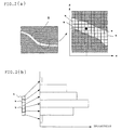
- In the above light-section method, as shown in Fig. 2 (a), the positions of the gravity centers of a plurality of pixels "s" forming a slit image "S" showing a ridge line on the surface of the tire T which is illuminated and imaged by an area camera are calculated to obtain the 2-D coordinates of each position of the slit image "S".
- The inventors of the present invention paid attention to the fact that when a portion having a color different from the color of the base of a tire, such as a stain or discoloration, is included in an illuminated portion, light applied to the tire T has a wide wavelength distribution, the line width of the above slit image "S" becomes nonuniform, and the brightness of each pixel "s" becomes different as shown in Fig. 2 (b) and found that the appearance and shape of the workpiece can be detected from one slit image "S" at the same time by obtaining the density (or color) of the workpiece from data on the brightness of each pixel "s". The present invention has been accomplished based on this finding.
- That is, according to a first aspect of the present invention, there is provided a method of detecting the coordinates and brightness of a workpiece, comprising the steps of:
- moving a workpiece, floodlight means for applying slit light to the surface to be inspected of the workpiece and imaging means having an area camera for imaging a portion illuminated by the slit light relative to one another to image the workpiece; and
- detecting the coordinates and brightness of the workpiece from the pixel data of the area camera at the same time.
-
- According to a second aspect of the present invention, there is provided a method of inspecting a workpiece, comprising the steps of:
- moving a workpiece, floodlight means for applying slit light to the surface to be inspected of the workpiece and imaging means having an area camera for imaging a portion illuminated by the slit light relative to one another to image the workpiece; and
- inspecting the workpiece based on the coordinates and brightness of the workpiece calculated from the pixel data of the area camera.
-
- According to a third aspect of the present invention, there is provided a method of inspecting a workpiece, wherein the coordinates and brightness of a specific region of the workpiece are integrated to obtain the shape data and density data of the specific region.
- According to a fourth aspect of the present invention, there is provided a method of inspecting a workpiece, wherein the obtained shape data or density data is compared with the reference shape data or reference density data on the specific region of the workpiece to inspect the workpiece.
- According to a fifth aspect of the present invention, there is provided a method of inspecting a workpiece, wherein it is judged that the specific region of the workpiece is unacceptable when the size of a region in which the difference between the obtained shape data and reference shape data and/or the difference between the obtained density data and reference density data exceeds a preset threshold value becomes larger than a predetermined value.
- According to a sixth aspect of the present invention, there is provided a method of inspecting a workpiece, wherein the workpiece is inspected based on surface unevenness calculated from the obtained shape data or the degree of density calculated from the obtained density data.
- According to a seventh aspect of the present invention, there is provided a method of inspecting a workpiece, wherein three white slit beams and a color camera are used to detect the shape and color of the workpiece at the same time.
- According to an eighth aspect of the present invention, there is provided an apparatus for detecting the appearance and shape of a workpiece by detecting the coordinates and brightness of the workpiece, comprising:
- floodlight means for applying slit light to the surface to be inspected of the workpiece;
- an area camera for imaging a portion illuminated by the slit light;
- means of moving the floodlight means, the imaging means and the workpiece relative to one another;
- means of calculating the coordinates of the workpiece from the pixel data of the area camera;
- means of calculating the brightness of the workpiece from the pixel data of the area camera; and
- means of detecting the appearance of the workpiece based on the calculated brightness.
-
- According to a ninth aspect of the present invention, there is provided an apparatus for detecting a workpiece, wherein white light is used as the slit light and a color camera is used as the imaging means.
- According to a tenth aspect of the present invention, there is provided an apparatus for inspecting a workpiece, comprising:
- the detection apparatus of the eighth or ninth aspect;
- means of storing reference data on the appearance and shape of the workpiece; and
- means of judging whether the shape and appearance of the workpiece are acceptable or not by comparing data on the appearance and shape of the workpiece obtained by the appearance and shape detection apparatus with the reference data.
-
-
- Fig. 1 is a diagram showing the constitution of a tire appearance and shape inspection apparatus according to a preferred embodiment of the present invention;
- Figs. 2(a) and 2(b) are diagrams for explaining the measurement principles of the present invention;
- Fig. 3 is a diagram showing another example of the tire appearance and shape inspection method of the present invention;
- Fig. 4 is a diagram showing still another example of the tire appearance and shape inspection method of the present invention; and
- Fig. 5 is a diagram showing the constitution of a tire appearance and shape inspection apparatus of the prior art.
-
- Preferred embodiments of the present invention will be described hereinbelow with reference to the accompanying drawings.
- Fig. 1 is a diagram showing the constitution of a tire appearance and shape inspection apparatus according to a preferred embodiment of the present invention. In Fig. 1,
reference numeral 10 denotes floodlight means for applying white slit light to the surface to be inspected of a tire T as a workpiece mounted on a rotary table 2 turned by amotor 1, 20 a color CCD camera, having pixels on a plane, for imaging a portion L illuminated by the above slit light of the turning tire T, 30 a tire judging unit for judging whether the shape and appearance of the above tire are acceptable or not by detecting the shape and appearance of the tire T from an image obtained by thecolor CCD camera above motor - The
tire judging unit 30 comprises coordinate computing means 31 for obtaining data on the 3-D coordinates of the tire T from an image (slit image "S") of a ridge line on the surface of the tire T imaged by thecolor CCD camera 20 and the rotation angle of the tire T detected by the rotation angle detection means 4, shapeimage forming means 32 for re-forming a 3-D image of the tire T by collecting the above 3-D coordinate data of one round of the tire, brightness computing means 33 for computing brightness data on R, G and B computed from the above slit image "S", appearance image forming means 34 for re-forming a color image of the tire T from the above brightness data and 3-D coordinate data, shape judging means 36 and appearance judging means 37 for comparing the obtained 3-D image and color image of the tire T with the above reference data, and overall judging means 38 for judging whether the tire T is acceptable or not. - A description is subsequently given of the method of inspecting the appearance and shape of the tire with the above apparatus.
- The
motor 1 is first driven by the motor drive and control means 3 to turn the rotary table 2 mounting the tire T to be inspected, white slit light is applied to the above turning tire T from the floodlight means 10 comprising a white light source such as a white laser or halogen lamp to image the illuminated portion L of the tire T with thecolor CCD camera 20 so as to obtain image data (slit image "S") on the ridge line on the surface of the tire T, and the image data is sent to the coordinate computing means 31 of thetire judging unit 30. - As shown in Fig. 2(a), the coordinate computing means 31 computes the positions of the gravity centers of illuminated pixels "s", out of the plurality of pixels forming the above slit image "S", to obtain the 2-D coordinates (x, z) of each position of the above slit image "S", and the 3-D coordinate data (x, y, z) of the tire T are obtained from the 2-D coordinates (x, z) and the rotation angle of the tire T detected by the above rotation angle detection means 4. The shape image forming means 32 computes the above 3-D coordinate data (3-D shape data) of one round of the tire by collecting the slit image "S" for each to detect the coordinates of the tire T as the workpiece and process the 3-D data to re-form a 3-D image of the tire T. As shown in Fig. 2(b), the brightness computing means 33 integrates the brightness's of the pixels "s" used for the computation of the above positions of the gravity centers to detect the brightness of the tire T as the workpiece so as to obtain brightness data at the above 3-D coordinate position (x, Y, z).
- In the above figures, only one color is shown. In this embodiment, this is made on R, G and B colors to compute brightness data (3-D brightness data) at the 3-D coordinate position (x, y, z). The appearance image forming means 34 processes an image by using the above 3-D coordinate brightness data and the 3-D coordinate data (x, y, z) of the tire T to re-form a color image or shaded image of the tire T.
- The 3-D image and color image or shaded image of the tire T which have been processed are compared with tire appearance and shape data pre-stored in the tire information storage means 35 by the shape judging means 36 and the appearance judging means 37 respectively to judge whether the circularity, surface unevenness and scratch, or appearance such as discoloration or stains and shape of the tire are acceptable or not, and the overall judging means 38 finally judges whether the tire is acceptable or not to inspect the tire T as the workpiece.
- For the actual inspection of the appearance and shape of the tire, it is not necessary to form the 3-D data or 3-D image of the above tire T and compare all of it with the reference data. For instance, the coordinates and brightness of a specific region such as an inner side portion or inner crown portion are estimated to compute the shape data of the specific region, and the 3-D shape data or 3-D image of the specific region is compared with the tire shape data of the above specific region pre-stored in the tire information storage means 35 to inspect the shape of the above tire T. That is, since shape and size reference values can be set by comparison for each specific region, whether the workpiece is acceptable or not can be judged more easily. The shape of the tire T may be inspected by comparing surface unevenness calculated from the above obtained shape data with the previously set threshold value (reference shape data) instead of comparison with data on the shape of the above tire. Alternatively, whether the shape of the tire is acceptable or not may be judged based on surface unevenness observed from a 3-D image of the tire T.
- When the comparison of 3-D density data or color image is made on a wide region to inspect discoloration or stains, or when the above comparison is made on a narrow specific region such as an inner crown portion or shoulder portion to inspect the exposition of a cord, the appearance of the above tire T can be inspected efficiently. Even in this case, the degree of density calculated from density data may be compared with the preset threshold value (reference density data) to inspect the appearance of the above tire T or to judge whether the appearance of the tire is acceptable or not based on the degree of density observed from a color image (or shaded image) of the above tire T in place of comparison with data on the appearance of the above tire.
- It may be judged that a specific region is unacceptable when the size of the region in which the difference between the above obtained 3-D shape data and the above tire shape data and/or the difference between the obtained 3-D density data and the above tire appearance data exceed(s) the preset threshold value becomes larger than a predetermined value.
- For example, for judgment on the shape of an inner shoulder portion or inner side portion, when a portion having a height larger than a predetermined value exists over a predetermined length or more in a peripheral direction, it is considered that the inner shoulder portion or the inner side portion is unacceptable. For appearance inspection, it is judged that the appearance of the above side portion is unacceptable when a region having a brightness outside a predetermined range considered as a defect has a predetermined area or more in the side portion.
- According to this embodiment of the present invention, the tire mounted on the rotary table 2 is imaged by the floodlight means 10 for applying white slit light and the
color CCD camera 20 for imaging a portion illuminated by the above slit light while the tire T is turned, and the coordinates and brightness of the above tire T are calculated from the above obtained image data by the coordinate computing means 31 and the brightness computing means 33 to detect the shape and color of the above tire T. Therefore, the shape and appearance of the tire T can be inspected at the same time with a simple structure. - Since the shape and color are detected from a single slit image in the present invention, misregistrations in shape and color caused by the displacement of a line portion which are seen in the prior art do not occur, thereby making it possible to obtain an accurate 3-D image and color image of the tire T.
- In the above embodiment, the workpiece is a product tire T. The present invention is not limited to this workpiece and may be a tire or tire constituting member before vulcanization, mechanical part or golf head whose appearance and shape must be inspected.
- In the above embodiment, the
color CCD camera 20 is used to obtain a color image of the tire T. When an appearance image is a monochromatic image and not satisfactory, one-color slit light and a monochromatic CCD camera may be used to obtain a shaded image of the tire T. To obtain a monochromatic image, a white laser does not need to be used as a light source. - To obtain a color image, slit beams may be applied to the tire T from R, G and B one-color lasers as light sources at predetermined intervals to take a color image with monochromatic CCD cameras. In this case, three lines (monochromatic images) A, B and C which are shifted from one another by the above time interval are obtained as slit images as shown in Fig. 3. When the brightness's of R, G and B are calculated from these lines, a color image of the tire T can be obtained without using the
color CCD camera 20. - Alternatively, light beams from a one-color laser (R) and G and B one-color LED's as light sources may be used to take a color image with the
color CCD camera 20. In this case, a slit image P obtained with the one-color laser and a line Q obtained with the one-color LED's adjacent to the above slit image are obtained as shown in Fig. 4. By computing the coordinates of the tire T from the above slit image P and the brightness's of R, G and B from the above slit image P and the line Q, a color image of the tire T can be obtained. - As described above, according to the present invention, a workpiece, floodlight means for applying slit light to the surface to be inspected of the workpiece, and imaging means having an area camera for imaging a portion illuminated by the slit light are moved relative to one another to image the above workpiece, and the coordinates and brightness of the workpiece are calculated from the pixel data of the area camera to detect the shape and density (or color) of the workpiece and to inspect the shape and appearance of the above workpiece at the same time. Therefore, the shape and appearance of the tire T can be inspected accurately at the same time with a simple structure.
Claims (10)
- A method of detecting a workpiece, comprising the steps of:moving a workpiece, floodlight means for applying slit light to the surface to be inspected of the workpiece and imaging means having an area camera for imaging a portion illuminated by the slit light relative to one another to image the workpiece; anddetecting the coordinates and brightness of the workpiece from the pixel data of the area camera.
- A method of inspecting a workpiece, comprising the steps of:moving a workpiece, floodlight means for applying slit light to the surface to be inspected of the workpiece and imaging means having an area camera for imaging a portion illuminated by the slit light relative to one another to image the workpiece; andinspecting the workpiece based on the coordinates and brightness of the workpiece calculated from the pixel data of the area camera.
- The method of inspecting a workpiece according to claim 2, wherein the coordinates and brightness of a specific region of the workpiece are integrated to obtain the shape data and density data of the specific region.
- The method of inspecting a workpiece according to claim 2 or 3, wherein the obtained shape data or density data is compared with the reference shape data or reference density data on the specific region of the workpiece to inspect the workpiece.
- The method of inspecting a workpiece according to claim 4, wherein it is judged that the specific region of the workpiece is unacceptable when the size of a region in which the difference between the obtained shape data and reference shape data and/or the difference between the obtained density data and reference density data exceeds a preset threshold value becomes larger than a predetermined value.
- The method of inspecting a workpiece according to claim 2 or 3, wherein the workpiece is inspected based on surface unevenness calculated from the obtained shape data or the degree of density calculated from the obtained density data.
- The method of inspecting a workpiece according to any one of claims 1 to 6, wherein white slit beams and a color camera are used to detect the shape and color of the workpiece at the same time.
- An apparatus for detecting a workpiece, comprising:floodlight means for applying slit light to the surface to be inspected of the workpiece;an area camera for imaging a portion illuminated by the slit light;means of moving the floodlight means, the imaging means and the workpiece relative to one another;means of calculating the coordinates of the workpiece from the pixel data of the area camera;means of calculating the brightness of the workpiece from the pixel data of the area camera; andmeans of detecting the appearance of the workpiece based on the calculated brightness.
- The apparatus for detecting a workpiece according to claim 8, wherein white light is used as the slit light and a color camera is used as the imaging means.
- An apparatus for inspecting a workpiece, comprising:the appearance and shape detection apparatus of claim 8 or 9;means of storing reference data on the appearance and shape of the workpiece; andmeans of judging whether the shape and appearance of the workpiece are acceptable or not by comparing data on the appearance and shape of the workpiece obtained by the appearance and shape detection apparatus with the reference data.
Applications Claiming Priority (3)
| Application Number | Priority Date | Filing Date | Title |
|---|---|---|---|
| JP2002044449 | 2002-02-21 | ||
| JP2002044449A JP2003240521A (en) | 2002-02-21 | 2002-02-21 | Method and apparatus for inspection of external appearance and shape of specimen |
| PCT/JP2003/001915 WO2003071224A1 (en) | 2002-02-21 | 2003-02-21 | Method of detecting object of detection and device therefor, and method of inspecting object of inspection and device therefor |
Publications (3)
| Publication Number | Publication Date |
|---|---|
| EP1477765A1 true EP1477765A1 (en) | 2004-11-17 |
| EP1477765A4 EP1477765A4 (en) | 2009-12-09 |
| EP1477765B1 EP1477765B1 (en) | 2016-05-18 |
Family
ID=27750549
Family Applications (1)
| Application Number | Title | Priority Date | Filing Date |
|---|---|---|---|
| EP03706990.3A Expired - Fee Related EP1477765B1 (en) | 2002-02-21 | 2003-02-21 | Method of detecting object of detection and device therefor, and method of inspecting object of inspection and device therefor |
Country Status (4)
| Country | Link |
|---|---|
| US (1) | US7421108B2 (en) |
| EP (1) | EP1477765B1 (en) |
| JP (1) | JP2003240521A (en) |
| WO (1) | WO2003071224A1 (en) |
Cited By (16)
| Publication number | Priority date | Publication date | Assignee | Title |
|---|---|---|---|---|
| EP1757902A1 (en) * | 2005-08-24 | 2007-02-28 | DeguDent GmbH | Method and apparatus for measuring the shape of a dental object |
| EP1792685A2 (en) | 2005-12-02 | 2007-06-06 | The Goodyear Tire & Rubber Company | Method and apparatus for identifying three dimensional coordinates on a tire |
| DE102006014070A1 (en) * | 2006-03-27 | 2007-10-11 | Mähner, Bernward | Device and method for testing a tire, in particular by means of an interferometric measuring method |
| DE102006015123A1 (en) * | 2006-03-31 | 2007-10-18 | Mähner, Bernward | Device and method for testing a tire, in particular by means of an interferometric measuring method |
| EP2023078A1 (en) * | 2007-08-06 | 2009-02-11 | Kabushiki Kaisha Kobe Seiko Sho | Tire shape measuring system |
| WO2009077539A2 (en) * | 2007-12-19 | 2009-06-25 | Societe De Technologie Michelin | Method for processing a three-dimensional image of the surface of a tyre so that it can be used to inspect the said surface |
| WO2009077537A1 (en) * | 2007-12-19 | 2009-06-25 | Societe De Technologie Michelin | Method of evaluation by comparison of an acquired image with a reference image |
| EP2078955A1 (en) * | 2006-11-02 | 2009-07-15 | Bridgestone Corporation | Method and device for inspecting tire surface |
| ITTO20101071A1 (en) * | 2010-12-27 | 2012-06-28 | Bridgestone Corp | METHOD AND MEASUREMENT STATION TO DETECT THE COORDINATES OF A SURFACE OF A TIRE UNDER LOAD |
| CN103168220A (en) * | 2010-10-19 | 2013-06-19 | 米其林企业总公司 | Method for identifying and defining basic patterns forming the tread design of a tyre |
| CN103477183A (en) * | 2011-04-20 | 2013-12-25 | 株式会社神户制钢所 | Tire surface shape measuring device and tire surface shape measuring method |
| EP2322899A4 (en) * | 2008-08-26 | 2015-10-28 | Bridgestone Corp | Specimen roughness detecting method, and apparatus for the method |
| CN105190277A (en) * | 2012-12-21 | 2015-12-23 | 倍耐力轮胎股份公司 | Method and apparatus for controlling tyres or related semi-finished products in a production line |
| WO2016103131A1 (en) * | 2014-12-22 | 2016-06-30 | Pirelli Tyre | Method and apparatus for detecting defects on tyres in a tyre production process |
| CN106104201A (en) * | 2014-04-07 | 2016-11-09 | 横滨橡胶株式会社 | The marking inspection method of tire-mold and device |
| WO2020169833A1 (en) * | 2019-02-22 | 2020-08-27 | Safran Electronics & Defense | Method for detecting a degradation of a wheel tyre |
Families Citing this family (48)
| Publication number | Priority date | Publication date | Assignee | Title |
|---|---|---|---|---|
| JP4419481B2 (en) * | 2003-09-03 | 2010-02-24 | 横浜ゴム株式会社 | Method and apparatus for measuring tire shape |
| JP4679073B2 (en) * | 2004-05-18 | 2011-04-27 | 株式会社ブリヂストン | Tire unevenness pattern inspection method and tire unevenness pattern inspection apparatus |
| WO2006054775A1 (en) * | 2004-11-22 | 2006-05-26 | Bridgestone Corporation | External-appearance inspection apparatus |
| CA2556533A1 (en) * | 2005-08-24 | 2007-02-24 | Degudent Gmbh | Method of determining the shape of a dental technology object and apparatus performing the method |
| US20070177788A1 (en) * | 2006-01-31 | 2007-08-02 | David Liu | System and method for detecting wafer failure in wet bench applications |
| DE502006009454D1 (en) * | 2006-03-23 | 2011-06-16 | Bernward Maehner | OTHER OBJECTS |
| DE102006014058B4 (en) * | 2006-03-27 | 2008-04-17 | Mähner, Bernward | Apparatus and method for optically testing a tire |
| JP4977415B2 (en) * | 2006-07-21 | 2012-07-18 | 株式会社ブリヂストン | Apparatus and method for creating reference shape data for tire inspection |
| JP4512578B2 (en) | 2006-10-27 | 2010-07-28 | 株式会社ブリヂストン | Separation filter determination device and tire inspection device |
| EP2136178A1 (en) * | 2007-04-05 | 2009-12-23 | Nikon Corporation | Geometry measurement instrument and method for measuring geometry |
| DE102007038176A1 (en) * | 2007-08-13 | 2009-02-19 | Steinbichler Optotechnik Gmbh | tire testing |
| FR2925706B1 (en) * | 2007-12-19 | 2010-01-15 | Soc Tech Michelin | DEVICE FOR EVALUATING THE SURFACE OF A TIRE. |
| JP5052387B2 (en) * | 2008-04-04 | 2012-10-17 | 株式会社ブリヂストン | Inspection method and apparatus for inner surface of hollow body |
| EP2112465A1 (en) * | 2008-04-24 | 2009-10-28 | Snap-on Equipment Srl a unico socio. | Parameter detection system for wheels |
| JP5053947B2 (en) * | 2008-07-15 | 2012-10-24 | 株式会社ブリヂストン | Shape quality determination method and shape quality determination device |
| FR2938330A1 (en) | 2008-11-07 | 2010-05-14 | Michelin Soc Tech | EVALUATION OF THE SURFACE SURFACE OF A PNEUMATIC BY STEREOVISION ACTIVE |
| JP5546786B2 (en) * | 2009-03-25 | 2014-07-09 | 株式会社ブリヂストン | Inspection object inspection apparatus, inspection method, and program |
| EP2353890A1 (en) * | 2010-01-29 | 2011-08-10 | Snap-on Equipment Srl a unico socio | Apparatus and method of determing geometrical dimensions of a tyre with optical sensors |
| JP5837283B2 (en) * | 2010-03-18 | 2015-12-24 | 株式会社ブリヂストン | Tire appearance inspection method and appearance inspection apparatus |
| JP5620139B2 (en) * | 2010-04-02 | 2014-11-05 | 株式会社ブリヂストン | Tire appearance inspection method and appearance inspection apparatus |
| US20120067997A1 (en) * | 2010-09-21 | 2012-03-22 | Ofs Fitel, Llc | Optical Fiber Spool Inspection System |
| US8824878B2 (en) * | 2010-11-25 | 2014-09-02 | Toyo Tire & Rubber Co., Ltd. | Illumination device and inspection device of tire |
| JP5443435B2 (en) | 2011-05-17 | 2014-03-19 | シャープ株式会社 | Tire defect detection method |
| DE102012202271A1 (en) * | 2011-07-11 | 2013-01-17 | Robert Bosch Gmbh | Apparatus and method for tire testing |
| JP5882730B2 (en) * | 2011-12-28 | 2016-03-09 | 株式会社ブリヂストン | Appearance inspection apparatus and appearance inspection method |
| JP5978002B2 (en) * | 2012-05-22 | 2016-08-24 | リコーエレメックス株式会社 | Inspection method and appearance inspection device |
| ITMI20121613A1 (en) * | 2012-09-27 | 2014-03-28 | Pirelli | METHOD FOR THE CONTROL OF THE PRODUCTION OF TIRES FOR VEHICLE WHEELS |
| JP6074284B2 (en) * | 2013-02-06 | 2017-02-01 | 株式会社ブリヂストン | Method and apparatus for measuring shape of belt-like rubber member |
| JP2014190825A (en) * | 2013-03-27 | 2014-10-06 | Kobe Steel Ltd | Data processing method of tire shape inspection device, data processing program of tire shape inspection device, and data processing device of tire shape inspection device |
| US10063837B2 (en) * | 2013-07-25 | 2018-08-28 | TIREAUDIT.COM, Inc. | System and method for analysis of surface features |
| FR3011079B1 (en) * | 2013-09-26 | 2015-09-25 | Michelin & Cie | INSPECTION METHOD AND PNEUMATIC INSPECTION LINE |
| JP5775132B2 (en) * | 2013-11-01 | 2015-09-09 | 株式会社ブリヂストン | Tire inspection equipment |
| EP3106860B1 (en) | 2014-02-12 | 2020-01-29 | The Yokohama Rubber Co., Ltd. | Tire inner surface imaging method and device |
| MX370194B (en) * | 2014-12-05 | 2019-12-04 | Pirelli | Method and apparatus for checking tyres, in a process and in a plant for manufacturing tyres for vehicle wheels. |
| JP6691541B2 (en) * | 2014-12-22 | 2020-04-28 | ピレリ・タイヤ・ソチエタ・ペル・アツィオーニ | Method and apparatus for checking tires on a production line |
| EP3237834B1 (en) | 2014-12-22 | 2020-02-19 | Pirelli Tyre S.p.A. | Apparatus for controlling tyres in a production line |
| BR112018011850B1 (en) | 2015-12-16 | 2022-10-11 | Pirelli Tyre S.P.A. | METHOD AND APPLIANCE TO CHECK A TIRE |
| US10670497B2 (en) | 2015-12-16 | 2020-06-02 | Pirelli Tyre S.P.A | Device and method for analysis of tyres comprising first and second image acquistion systems |
| CN108431573B (en) * | 2015-12-22 | 2020-10-16 | 倍耐力轮胎股份公司 | Station and method for inspecting tyres |
| US10809158B2 (en) | 2015-12-28 | 2020-10-20 | Pirelli Tyre S.P.A. | Apparatus and method for checking tyres |
| EP3397938B1 (en) | 2015-12-28 | 2019-08-28 | Pirelli Tyre S.p.A. | Apparatus for checking tyres |
| RU2722779C2 (en) * | 2015-12-28 | 2020-06-03 | Пирелли Тайр С.П.А. | Tire monitoring device |
| US10789773B2 (en) | 2016-03-04 | 2020-09-29 | TIREAUDIT.COM, Inc. | Mesh registration system and method for diagnosing tread wear |
| US11472234B2 (en) | 2016-03-04 | 2022-10-18 | TIREAUDIT.COM, Inc. | Mesh registration system and method for diagnosing tread wear |
| CN105717119B (en) * | 2016-03-24 | 2018-07-10 | 深圳市浩锐拓科技有限公司 | Double harness color detection means |
| FI127185B (en) * | 2016-06-27 | 2017-12-29 | Nokian Renkaat Oyj | A method of studying a vehicle tire and a studded vehicle tire |
| TWI632342B (en) * | 2016-11-30 | 2018-08-11 | 財團法人工業技術研究院 | Measuring equipment and measuring methods |
| CN116518860B (en) * | 2023-04-27 | 2023-12-22 | 冠县华超金属科技有限公司 | Wheel runout detection device and method |
Citations (4)
| Publication number | Priority date | Publication date | Assignee | Title |
|---|---|---|---|---|
| EP0458168A2 (en) * | 1990-05-24 | 1991-11-27 | National Research Council Of Canada | Three dimensional color imaging |
| WO1997033139A1 (en) * | 1996-03-04 | 1997-09-12 | National Research Council Of Canada | Three-dimensional color imaging |
| JP2001280916A (en) * | 2000-03-31 | 2001-10-10 | Minolta Co Ltd | Instrument for three-dimensional measurement |
| WO2002082009A1 (en) * | 2001-04-06 | 2002-10-17 | Intek Plus Co., Ltd. | Method and apparatus for measuring the three-dimensional surface shape of an object using color informations of light reflected by the object |
Family Cites Families (9)
| Publication number | Priority date | Publication date | Assignee | Title |
|---|---|---|---|---|
| JPH01284743A (en) * | 1988-05-10 | 1989-11-16 | Toshiba Corp | Method and device for appearance inspection of resin mold of semiconductor device |
| JP2629528B2 (en) | 1992-08-21 | 1997-07-09 | ティアック株式会社 | Magnetic disk drive |
| JPH0684305U (en) * | 1993-05-13 | 1994-12-02 | 株式会社東海理化電機製作所 | Shape measuring device with color display function |
| JP3333048B2 (en) * | 1994-06-28 | 2002-10-07 | 三菱原子燃料株式会社 | Cylindrical inspection equipment |
| JP2904069B2 (en) * | 1995-08-28 | 1999-06-14 | ブリヂストンスポーツ株式会社 | Method for inspecting appearance of spherical object and inspection apparatus therefor |
| JP3949796B2 (en) | 1997-11-06 | 2007-07-25 | 株式会社ブリヂストン | Tire shape determination device |
| JP2001012920A (en) | 1999-07-01 | 2001-01-19 | Nippon Steel Corp | Shape detector |
| JP4514007B2 (en) * | 1999-12-28 | 2010-07-28 | 株式会社ブリヂストン | Method and apparatus for inspecting appearance of subject |
| JP2003139714A (en) * | 2001-11-06 | 2003-05-14 | Ube Ind Ltd | Method for evaluating surface condition of object |
-
2002
- 2002-02-21 JP JP2002044449A patent/JP2003240521A/en active Pending
-
2003
- 2003-02-21 US US10/504,002 patent/US7421108B2/en not_active Expired - Fee Related
- 2003-02-21 WO PCT/JP2003/001915 patent/WO2003071224A1/en active Application Filing
- 2003-02-21 EP EP03706990.3A patent/EP1477765B1/en not_active Expired - Fee Related
Patent Citations (4)
| Publication number | Priority date | Publication date | Assignee | Title |
|---|---|---|---|---|
| EP0458168A2 (en) * | 1990-05-24 | 1991-11-27 | National Research Council Of Canada | Three dimensional color imaging |
| WO1997033139A1 (en) * | 1996-03-04 | 1997-09-12 | National Research Council Of Canada | Three-dimensional color imaging |
| JP2001280916A (en) * | 2000-03-31 | 2001-10-10 | Minolta Co Ltd | Instrument for three-dimensional measurement |
| WO2002082009A1 (en) * | 2001-04-06 | 2002-10-17 | Intek Plus Co., Ltd. | Method and apparatus for measuring the three-dimensional surface shape of an object using color informations of light reflected by the object |
Non-Patent Citations (1)
| Title |
|---|
| See also references of WO03071224A1 * |
Cited By (40)
| Publication number | Priority date | Publication date | Assignee | Title |
|---|---|---|---|---|
| EP1757902A1 (en) * | 2005-08-24 | 2007-02-28 | DeguDent GmbH | Method and apparatus for measuring the shape of a dental object |
| CN1931110B (en) * | 2005-08-24 | 2011-08-31 | 德固萨有限责任公司 | Method of determining the shape of a dental technology object and apparatus for per-forming the method |
| EP1792685A2 (en) | 2005-12-02 | 2007-06-06 | The Goodyear Tire & Rubber Company | Method and apparatus for identifying three dimensional coordinates on a tire |
| EP1792685A3 (en) * | 2005-12-02 | 2007-08-29 | The Goodyear Tire & Rubber Company | Method and apparatus for identifying three dimensional coordinates on a tire |
| US7702134B2 (en) | 2005-12-02 | 2010-04-20 | The Goodyear Tire & Rubber Company | Method and apparatus for identifying three dimensional coordinates on a tire |
| DE102006014070A1 (en) * | 2006-03-27 | 2007-10-11 | Mähner, Bernward | Device and method for testing a tire, in particular by means of an interferometric measuring method |
| DE102006014070B4 (en) * | 2006-03-27 | 2008-02-07 | Mähner, Bernward | Device and method for testing a tire, in particular by means of an interferometric measuring method |
| US8614740B2 (en) | 2006-03-27 | 2013-12-24 | Bernward Maehner | Device and method for inspecting a tire, in particular using an interferometric measuring method |
| DE102006015123B4 (en) * | 2006-03-31 | 2008-03-20 | Mähner, Bernward | Device and method for testing a tire, in particular by means of an interferometric measuring method |
| DE102006015123A1 (en) * | 2006-03-31 | 2007-10-18 | Mähner, Bernward | Device and method for testing a tire, in particular by means of an interferometric measuring method |
| US7856869B2 (en) | 2006-03-31 | 2010-12-28 | Stefan Dengler | Device and method for checking a tire in particular by means of an interferometric measuring method |
| US8059279B2 (en) | 2006-11-02 | 2011-11-15 | Bridgestone Corporation | Method and system for inspecting tire surface |
| EP2078955A1 (en) * | 2006-11-02 | 2009-07-15 | Bridgestone Corporation | Method and device for inspecting tire surface |
| EP2078955A4 (en) * | 2006-11-02 | 2009-12-23 | Bridgestone Corp | Method and device for inspecting tire surface |
| US7755772B2 (en) | 2007-08-06 | 2010-07-13 | Kobe Steel, Ltd. | Tire shape measuring system |
| EP2023078A1 (en) * | 2007-08-06 | 2009-02-11 | Kabushiki Kaisha Kobe Seiko Sho | Tire shape measuring system |
| WO2009077539A3 (en) * | 2007-12-19 | 2010-01-21 | Societe De Technologie Michelin | Method for processing a three-dimensional image of the surface of a tyre so that it can be used to inspect the said surface |
| FR2925687A1 (en) * | 2007-12-19 | 2009-06-26 | Michelin Soc Tech | METHOD OF EVALUATION BY COMPARISON OF AN ACQUIRED IMAGE WITH A REFERENCE IMAGE. |
| WO2009077537A1 (en) * | 2007-12-19 | 2009-06-25 | Societe De Technologie Michelin | Method of evaluation by comparison of an acquired image with a reference image |
| WO2009077539A2 (en) * | 2007-12-19 | 2009-06-25 | Societe De Technologie Michelin | Method for processing a three-dimensional image of the surface of a tyre so that it can be used to inspect the said surface |
| US8498467B2 (en) | 2007-12-19 | 2013-07-30 | Compagnie Generale Des Etablissements Michelin | Method for processing a three-dimensional image of the surface of a tire so that it can be used to inspect the said surface |
| US8498466B2 (en) | 2007-12-19 | 2013-07-30 | Compagnie Generale Des Etablissements Michelin | Method of evaluation by comparison of an acquired image with a reference image |
| EP2322899A4 (en) * | 2008-08-26 | 2015-10-28 | Bridgestone Corp | Specimen roughness detecting method, and apparatus for the method |
| CN103168220A (en) * | 2010-10-19 | 2013-06-19 | 米其林企业总公司 | Method for identifying and defining basic patterns forming the tread design of a tyre |
| ITTO20101071A1 (en) * | 2010-12-27 | 2012-06-28 | Bridgestone Corp | METHOD AND MEASUREMENT STATION TO DETECT THE COORDINATES OF A SURFACE OF A TIRE UNDER LOAD |
| CN103477183A (en) * | 2011-04-20 | 2013-12-25 | 株式会社神户制钢所 | Tire surface shape measuring device and tire surface shape measuring method |
| CN105190277B (en) * | 2012-12-21 | 2018-04-10 | 倍耐力轮胎股份公司 | Tire or related process of semi-finished and device are controlled in production line |
| CN105190277A (en) * | 2012-12-21 | 2015-12-23 | 倍耐力轮胎股份公司 | Method and apparatus for controlling tyres or related semi-finished products in a production line |
| CN106104201B (en) * | 2014-04-07 | 2019-12-24 | 横滨橡胶株式会社 | Method and device for inspecting imprint of tire mold |
| CN106104201A (en) * | 2014-04-07 | 2016-11-09 | 横滨橡胶株式会社 | The marking inspection method of tire-mold and device |
| US10006836B2 (en) | 2014-12-22 | 2018-06-26 | Pirelli Tyre S.P.A. | Method and apparatus for detecting defects on tyres in a tyre production process |
| CN108093647A (en) * | 2014-12-22 | 2018-05-29 | 倍耐力轮胎股份公司 | The method and apparatus of the defects of for being detected in Tire production process on tire |
| RU2640673C1 (en) * | 2014-12-22 | 2018-01-11 | Пирелли Тайр С.П.А. | Method and device for detecting defects on tires when manufacturing tires |
| CN108093647B (en) * | 2014-12-22 | 2019-03-05 | 倍耐力轮胎股份公司 | Method and apparatus for detecting the defect on tire in Tire production process |
| WO2016103131A1 (en) * | 2014-12-22 | 2016-06-30 | Pirelli Tyre | Method and apparatus for detecting defects on tyres in a tyre production process |
| WO2020169833A1 (en) * | 2019-02-22 | 2020-08-27 | Safran Electronics & Defense | Method for detecting a degradation of a wheel tyre |
| FR3093183A1 (en) * | 2019-02-22 | 2020-08-28 | Safran Electronics & Defense | Method for detecting degradation of a tire on a wheel |
| CN113454435A (en) * | 2019-02-22 | 2021-09-28 | 赛峰电子与防务公司 | Method for detecting tire degradation |
| US11391648B2 (en) | 2019-02-22 | 2022-07-19 | Safran Electronics & Defense | Method for detecting a degradation of a wheel tire |
| CN113454435B (en) * | 2019-02-22 | 2022-08-26 | 赛峰电子与防务公司 | Method for detecting tire degradation |
Also Published As
| Publication number | Publication date |
|---|---|
| US20050058333A1 (en) | 2005-03-17 |
| WO2003071224A1 (en) | 2003-08-28 |
| US7421108B2 (en) | 2008-09-02 |
| EP1477765B1 (en) | 2016-05-18 |
| EP1477765A4 (en) | 2009-12-09 |
| JP2003240521A (en) | 2003-08-27 |
Similar Documents
| Publication | Publication Date | Title |
|---|---|---|
| EP1477765B1 (en) | Method of detecting object of detection and device therefor, and method of inspecting object of inspection and device therefor | |
| US7202957B2 (en) | Three-dimensional visual sensor | |
| JP5436431B2 (en) | Method and apparatus for detecting unevenness of subject | |
| US11216687B2 (en) | Image detection scanning method for object surface defects and image detection scanning system thereof | |
| JP4309439B2 (en) | Object take-out device | |
| JP6952218B2 (en) | Collision Prevention Methods and Laser Machining Tools | |
| JP6734253B2 (en) | Imaging device including a visual sensor for imaging a workpiece | |
| JP4894628B2 (en) | Appearance inspection method and appearance inspection apparatus | |
| JP2007206797A (en) | Image processing method and image processor | |
| US11674907B2 (en) | Method and device for recognising and analysing surface defects in three-dimensional objects having a reflective surface, in particular motor vehicle bodies | |
| JP2009041934A (en) | Apparatus and method for shape measurement | |
| US5566244A (en) | Method of inspecting a workpiece surface including a picturing system with a shortened focal plane | |
| JP2019507323A (en) | Tire inspection device | |
| CN110231352B (en) | Image inspection apparatus, image inspection method, and image inspection recording medium | |
| KR20210019014A (en) | Method and plant for determining the location of a point on a complex surface of space | |
| JP2005148010A (en) | Method and device for detecting shape and darkness of analyte | |
| US20170255181A1 (en) | Measurement apparatus, system, measurement method, and article manufacturing method | |
| EP3639002B1 (en) | Method for checking tyres | |
| JP6371742B2 (en) | Measuring device and acquisition method | |
| JP2004042118A (en) | Automatic copying controller of welding position and method for automatic copying welding | |
| JP3372014B2 (en) | Missing parts inspection equipment for engine external parts | |
| KR101412480B1 (en) | A method of measuring full and shawl width of tread of tire | |
| JP6611872B2 (en) | Measuring device | |
| KR102429699B1 (en) | Future car headlamp cover lens vision inspection device | |
| WO2021049326A1 (en) | Surface defect discerning device, appearance inspection device, and program |
Legal Events
| Date | Code | Title | Description |
|---|---|---|---|
| PUAI | Public reference made under article 153(3) epc to a published international application that has entered the european phase |
Free format text: ORIGINAL CODE: 0009012 |
|
| 17P | Request for examination filed |
Effective date: 20040816 |
|
| AK | Designated contracting states |
Kind code of ref document: A1 Designated state(s): AT BE BG CH CY CZ DE DK EE ES FI FR GB GR HU IE IT LI LU MC NL PT SE SI SK TR |
|
| A4 | Supplementary search report drawn up and despatched |
Effective date: 20091111 |
|
| 17Q | First examination report despatched |
Effective date: 20100511 |
|
| REG | Reference to a national code |
Ref country code: DE Ref legal event code: R079 Ref document number: 60348960 Country of ref document: DE Free format text: PREVIOUS MAIN CLASS: G01B0011240000 Ipc: G01M0017020000 |
|
| GRAP | Despatch of communication of intention to grant a patent |
Free format text: ORIGINAL CODE: EPIDOSNIGR1 |
|
| RIC1 | Information provided on ipc code assigned before grant |
Ipc: G01B 11/24 20060101ALI20151109BHEP Ipc: G01N 21/88 20060101ALI20151109BHEP Ipc: G01N 21/95 20060101ALI20151109BHEP Ipc: G01B 11/25 20060101ALI20151109BHEP Ipc: G06T 7/00 20060101ALI20151109BHEP Ipc: G01M 17/02 20060101AFI20151109BHEP |
|
| INTG | Intention to grant announced |
Effective date: 20151123 |
|
| GRAS | Grant fee paid |
Free format text: ORIGINAL CODE: EPIDOSNIGR3 |
|
| GRAA | (expected) grant |
Free format text: ORIGINAL CODE: 0009210 |
|
| AK | Designated contracting states |
Kind code of ref document: B1 Designated state(s): DE ES FR GB IT |
|
| REG | Reference to a national code |
Ref country code: GB Ref legal event code: FG4D |
|
| REG | Reference to a national code |
Ref country code: DE Ref legal event code: R096 Ref document number: 60348960 Country of ref document: DE |
|
| PG25 | Lapsed in a contracting state [announced via postgrant information from national office to epo] |
Ref country code: ES Free format text: LAPSE BECAUSE OF FAILURE TO SUBMIT A TRANSLATION OF THE DESCRIPTION OR TO PAY THE FEE WITHIN THE PRESCRIBED TIME-LIMIT Effective date: 20160518 |
|
| PG25 | Lapsed in a contracting state [announced via postgrant information from national office to epo] |
Ref country code: IT Free format text: LAPSE BECAUSE OF FAILURE TO SUBMIT A TRANSLATION OF THE DESCRIPTION OR TO PAY THE FEE WITHIN THE PRESCRIBED TIME-LIMIT Effective date: 20160518 |
|
| REG | Reference to a national code |
Ref country code: FR Ref legal event code: PLFP Year of fee payment: 15 |
|
| REG | Reference to a national code |
Ref country code: DE Ref legal event code: R097 Ref document number: 60348960 Country of ref document: DE |
|
| PLBE | No opposition filed within time limit |
Free format text: ORIGINAL CODE: 0009261 |
|
| STAA | Information on the status of an ep patent application or granted ep patent |
Free format text: STATUS: NO OPPOSITION FILED WITHIN TIME LIMIT |
|
| 26N | No opposition filed |
Effective date: 20170221 |
|
| GBPC | Gb: european patent ceased through non-payment of renewal fee |
Effective date: 20170221 |
|
| REG | Reference to a national code |
Ref country code: FR Ref legal event code: PLFP Year of fee payment: 16 |
|
| PG25 | Lapsed in a contracting state [announced via postgrant information from national office to epo] |
Ref country code: GB Free format text: LAPSE BECAUSE OF NON-PAYMENT OF DUE FEES Effective date: 20170221 |
|
| PGFP | Annual fee paid to national office [announced via postgrant information from national office to epo] |
Ref country code: FR Payment date: 20210224 Year of fee payment: 19 |
|
| PGFP | Annual fee paid to national office [announced via postgrant information from national office to epo] |
Ref country code: DE Payment date: 20210217 Year of fee payment: 19 |
|
| REG | Reference to a national code |
Ref country code: DE Ref legal event code: R119 Ref document number: 60348960 Country of ref document: DE |
|
| PG25 | Lapsed in a contracting state [announced via postgrant information from national office to epo] |
Ref country code: FR Free format text: LAPSE BECAUSE OF NON-PAYMENT OF DUE FEES Effective date: 20220228 |
|
| PG25 | Lapsed in a contracting state [announced via postgrant information from national office to epo] |
Ref country code: DE Free format text: LAPSE BECAUSE OF NON-PAYMENT OF DUE FEES Effective date: 20220901 |