EP1477397B1 - Amortisseur de direction de motocycle - Google Patents
Amortisseur de direction de motocycle Download PDFInfo
- Publication number
- EP1477397B1 EP1477397B1 EP20030706988 EP03706988A EP1477397B1 EP 1477397 B1 EP1477397 B1 EP 1477397B1 EP 20030706988 EP20030706988 EP 20030706988 EP 03706988 A EP03706988 A EP 03706988A EP 1477397 B1 EP1477397 B1 EP 1477397B1
- Authority
- EP
- European Patent Office
- Prior art keywords
- oil
- steering damper
- check ball
- piston
- passageway
- Prior art date
- Legal status (The legal status is an assumption and is not a legal conclusion. Google has not performed a legal analysis and makes no representation as to the accuracy of the status listed.)
- Expired - Lifetime
Links
- 230000007935 neutral effect Effects 0.000 claims description 13
- 230000007704 transition Effects 0.000 claims description 2
- 230000003247 decreasing effect Effects 0.000 abstract description 5
- 238000013016 damping Methods 0.000 description 9
- 238000010276 construction Methods 0.000 description 8
- 230000007423 decrease Effects 0.000 description 2
- 238000006073 displacement reaction Methods 0.000 description 2
- 230000006399 behavior Effects 0.000 description 1
- 238000001514 detection method Methods 0.000 description 1
- 239000002828 fuel tank Substances 0.000 description 1
- 230000004044 response Effects 0.000 description 1
Images
Classifications
-
- F—MECHANICAL ENGINEERING; LIGHTING; HEATING; WEAPONS; BLASTING
- F16—ENGINEERING ELEMENTS AND UNITS; GENERAL MEASURES FOR PRODUCING AND MAINTAINING EFFECTIVE FUNCTIONING OF MACHINES OR INSTALLATIONS; THERMAL INSULATION IN GENERAL
- F16F—SPRINGS; SHOCK-ABSORBERS; MEANS FOR DAMPING VIBRATION
- F16F9/00—Springs, vibration-dampers, shock-absorbers, or similarly-constructed movement-dampers using a fluid or the equivalent as damping medium
- F16F9/10—Springs, vibration-dampers, shock-absorbers, or similarly-constructed movement-dampers using a fluid or the equivalent as damping medium using liquid only; using a fluid of which the nature is immaterial
- F16F9/14—Devices with one or more members, e.g. pistons, vanes, moving to and fro in chambers and using throttling effect
- F16F9/16—Devices with one or more members, e.g. pistons, vanes, moving to and fro in chambers and using throttling effect involving only straight-line movement of the effective parts
- F16F9/18—Devices with one or more members, e.g. pistons, vanes, moving to and fro in chambers and using throttling effect involving only straight-line movement of the effective parts with a closed cylinder and a piston separating two or more working spaces therein
- F16F9/19—Devices with one or more members, e.g. pistons, vanes, moving to and fro in chambers and using throttling effect involving only straight-line movement of the effective parts with a closed cylinder and a piston separating two or more working spaces therein with a single cylinder and of single-tube type
-
- B—PERFORMING OPERATIONS; TRANSPORTING
- B62—LAND VEHICLES FOR TRAVELLING OTHERWISE THAN ON RAILS
- B62K—CYCLES; CYCLE FRAMES; CYCLE STEERING DEVICES; RIDER-OPERATED TERMINAL CONTROLS SPECIALLY ADAPTED FOR CYCLES; CYCLE AXLE SUSPENSIONS; CYCLE SIDE-CARS, FORECARS, OR THE LIKE
- B62K21/00—Steering devices
- B62K21/08—Steering dampers
-
- F—MECHANICAL ENGINEERING; LIGHTING; HEATING; WEAPONS; BLASTING
- F16—ENGINEERING ELEMENTS AND UNITS; GENERAL MEASURES FOR PRODUCING AND MAINTAINING EFFECTIVE FUNCTIONING OF MACHINES OR INSTALLATIONS; THERMAL INSULATION IN GENERAL
- F16F—SPRINGS; SHOCK-ABSORBERS; MEANS FOR DAMPING VIBRATION
- F16F9/00—Springs, vibration-dampers, shock-absorbers, or similarly-constructed movement-dampers using a fluid or the equivalent as damping medium
- F16F9/32—Details
- F16F9/50—Special means providing automatic damping adjustment, i.e. self-adjustment of damping by particular sliding movements of a valve element, other than flexions or displacement of valve discs; Special means providing self-adjustment of spring characteristics
- F16F9/512—Means responsive to load action, i.e. static load on the damper or dynamic fluid pressure changes in the damper, e.g. due to changes in velocity
-
- Y—GENERAL TAGGING OF NEW TECHNOLOGICAL DEVELOPMENTS; GENERAL TAGGING OF CROSS-SECTIONAL TECHNOLOGIES SPANNING OVER SEVERAL SECTIONS OF THE IPC; TECHNICAL SUBJECTS COVERED BY FORMER USPC CROSS-REFERENCE ART COLLECTIONS [XRACs] AND DIGESTS
- Y10—TECHNICAL SUBJECTS COVERED BY FORMER USPC
- Y10T—TECHNICAL SUBJECTS COVERED BY FORMER US CLASSIFICATION
- Y10T137/00—Fluid handling
- Y10T137/7722—Line condition change responsive valves
- Y10T137/7771—Bi-directional flow valves
- Y10T137/778—Axes of ports co-axial
-
- Y—GENERAL TAGGING OF NEW TECHNOLOGICAL DEVELOPMENTS; GENERAL TAGGING OF CROSS-SECTIONAL TECHNOLOGIES SPANNING OVER SEVERAL SECTIONS OF THE IPC; TECHNICAL SUBJECTS COVERED BY FORMER USPC CROSS-REFERENCE ART COLLECTIONS [XRACs] AND DIGESTS
- Y10—TECHNICAL SUBJECTS COVERED BY FORMER USPC
- Y10T—TECHNICAL SUBJECTS COVERED BY FORMER US CLASSIFICATION
- Y10T137/00—Fluid handling
- Y10T137/7722—Line condition change responsive valves
- Y10T137/7837—Direct response valves [i.e., check valve type]
- Y10T137/7869—Biased open
- Y10T137/7871—Weight biased
- Y10T137/7873—Ball valves
Definitions
- the present invention relates to a motorcycle steering damper according to the preamble of independent claim 1.
- a steering damper is provided between a steering system member such as a steering bracket and a vehicle body frame for absorbing disturbance from the road surface by virtue of a damping force generated on the steering damper so provided to thereby suppress the vibration of the front wheel system (for example, refer to JP-A- 05-201377 .
- the steering damper is constructed such that the interior of a cylinder is divided into two oil chambers by a piston which slides in the cylinder as a steering operation takes place, an oil hole (an orifice) is formed in the piston for providing a communication between the two oil chambers, and a bypass passageway is provided for allowing oil in one of the oil chambers to flow into the other oil chamber by bypassing the oil hole, whereby an electromagnetic valve is controlled based on the behaviors of the vehicle which are affected by vehicle speed, steering angle and load which are detected by sensors so that the bypass passageway is closed by the electromagnetic valve so as to increase quickly the damping force to thereby suppress the vibration of the front wheel system.
- BE 355 784 A the interior of a cylinder is divided into two oil chambers by a piston that slides in the cylinder as a steering operation takes place, and a passageway for providing a communication between the two oil chambers is provided in a portion other than the piston.
- US 4,773,514 A discloses a steering damper comprising a subsidiary chamber which is defined at an intermediate position along the length of a passageway and a check ball which is provided In the subsidiary chamber, wherein the check ball is adapted to move so as to reduce the cross-sectional area of the passageway when a steering speed exceeds a predetermined value and a differential pressure between the two oil chambers reaches or exceeds a predetermined value.
- the invention was made in view of the problems, and an object thereof is to provide a motorcycle steering damper which requires no electrical control but ensures mechanical operations and which can suppress the vibration of the front wheel system due to disturbance while ensuring the decrease in cost by decreasing the number of components and high reliability.
- Another steering damper is known from US 6,145,037 with a valve for varying the resistance to displacement from center of the vehicle depending upon the velocity of displacement.
- a motorcycle steering damper In which the interior of a cylinder is divided Into two oil chambers by a piston that is configured to slide in the cylinder as a steering operation takes place, and a passageway for providing a communication between the two oil chambers is provided in a portion other than the piston, wherein a subsidiary chamber is defined in the passageway at an intermediate position along the length of the passageway, and a check ball is provided In the subsidiary chamber; the check ball is adapted to move so as to reduce the cross-sectional area of the passageway when a steering speed exceeds a predetermined value and a differential pressure between the two oil chambers reaches or exceeds a certain value; a holding device is provided which Is configured to hold the check ball at a neutral position where the passageway is not closed by the check ball in a state In which the differential pressure Is smaller than the certain value; and the holding device is made up of a concavely curved surface formed on a floor of the subsidiary chamber or
- a motorcycle steering damper as set forth in the first aspect of the invention, characterized in that an oil hole is provided in the piston for providing a communication between the two oil chambers.
- a motorcycle steering damper as set forth in the first aspect of the invention, characterized in that a slit is formed on a transition surface between the passageway and the subsidiary chamber on which the check ball is seated when an internal pressure of the oil chamber is increased.
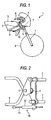
- Fig. 1 is a right side view of a front part of a motorcycle provided with a steering damper according to the invention
- Fig. 2 is a plan view of the front part of the motorcycle illustrating a construction in which the steering damper according to the invention is arranged
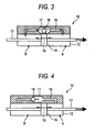
- Fig. 3 is a cross-sectional view of the steering damper according to the invention (when a bypass passageway is opened)
- Fig. 4 is a cross-sectional view of the steering damper according to the invention (when a bypass passageway is closed)
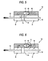
- Fig. 5 is a cross-sectional view of the steering damper according to the invention (when a bypass passageway is closed)
- Fig. 6 is a cross-sectional view of a steering damper according to another aspect of the invention
- Fig. 1 is a right side view of a front part of a motorcycle provided with a steering damper according to the invention
- Fig. 2 is a plan view of the front part of the motorcycle illustrating a construction in which the steering damper according
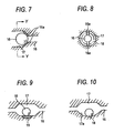
- FIG. 7 is a view illustrating in detail an X portion in Fig. 6
- Fig. 8 is a cross-sectional view taken along line Y-Y in Fig. 7
- Fig. 9 is a cross-sectional view showing a holding device (a magnet) of the invention for holding a check ball at a neutral position
- Fig. 10 is a cross-sectional view showing a holding device (a concavely curved surface) of the invention for holding the check ball at the neutral position
- Fig. 11 is a cross-sectional view showing a holding device (a spring) which does not belong to the invention for holding the check ball at the neutral position
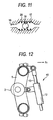
- Fig. 12 is a plan view of the motorcycle illustrating another example of arrangement of the steering damper according to the invention.
- Fig. 1 is a right side view of a front part of a motorcycle provided with a steering damper according to the invention
- Fig. 2 is a plan view of the front part of the motorcycle illustrating a construction in which the steering damper is arranged.
- reference numeral 2 denotes a head pipe located at an upper portion of the front of a vehicle body, and a steering shaft 3 is passed through and supported rotatably in the head pipe 2 and an upper bracket 4 and a lower bracket 5 are attached to the steering shaft 3 at upper and lower ends thereof, respectively.
- a handlebar 6 is attached to the upper bracket 4 and an upper portion of a front fork 7 is passed and supported between the upper bracket 4 and the lower bracket 5, a front wheel 8 being rotationally supported at a lower portion of the front fork 7.
- a vehicle body frame 9 is provided to extend from the head pipe 2 to the rear of the vehicle body, and a steering damper 10 according to the invention is provided on the right-hand side of the vehicle body in such a manner as to be interposed between the vehicle body frame 9 and the lower bracket 5.
- reference numeral 11 denotes a fuel tank.
- the steering damper 10 is constructed to incorporate a cylinder 12 and a piston rod 13 which is passed through the interior of the cylinder 12 in such a manner as tomove in response to an impact, and the cylinder 12 is attached to a right-hand side of the lower bracket 5, whereas the piston rod 13 is attached to a right-hand side of the vehicle body frame 9 at one end thereof.
- Figs. 3 to 5 are explanatory cross-sectional views of the steering damper.
- a piston 14 fittingly inserted into the cylinder 12 in such a manner as to slide therein is attached to the piston rod 13 which is passed through the inside of the cylinder 12, and oil chambers A, B are defined in the cylinder 12 by the piston 14, oil being fill in the oil chambers A, B. Then, an oil hole (orifice) 15 having a small diameter is opened in the piston 14 for providing a communication between the oil chambers A, B.
- a bypass passageway 16 is formed in a side of the cylinder 12 for allowing oil in one A (or B) of the oil chambers to flow into the other oil chamber B (orA) by bypassing the oil hole 15 formed in the piston 14, and a subsidiary chamber 17 is defined in the bypass passage 16 at an intermediate position along the length thereof.
- a metallic check ball 18 is accommodated in the interior of the subsidiary chamber 17. The metallic check ball 18 is adapted to move to close the bypass passageway 16 when the steering speed exceeds a predetermined value and a differential pressure between the two oil chambers A, B reaches or exceeds a certain value.
- the differential pressure between the two oil chambers A, B is so small that the check ball 18 within the subsidiary chamber 17 does not move by virtue of the differential pressure, and, as shown in Fig. 3 , the check ball 18 is located at a neutral position, wherein the bypass passageway 16 is in an opened state, whereby a communication is being provided between the two oil chambers A, B.
- oil within the oil chamber B passes mainly through the bypass passageway 16 which provides less resistance so as to flow into the oil chamber A, whereas a slight amount of oil in the oil chamber B passes through the oil hole 15 in the piston 14 so as to flow into the oil chamber A.
- a damping force generated in the steering damper 10 is small, and when the steering speed remains within the normal range, the rider can perform a smooth steering operation without any resistance.
- the check ball 18 is moved by virtue of the differential pressure.
- the check ball 18 is moved to close the bypass passageway 16 as shown in the drawing, and oil in the oil chamber A passes through only the oil hole 15 having the small diameter which is formed in the piston 14 so as to flow into the oil chamber B.
- the mechanical construction is adopted in which the check ball 18 is moved to close the bypass passageway 16 by the differential pressure as required, the necessity of a sensor or electrical control is obviated, and the vibration of the front wheel system due to disturbance can be suppressed while attempting to reduce the production costs by decreasing the number of components involved and to secure high reliability.
- Fig. 6 is an explanatory cross-sectional view of a steering damper according to another embodiment of the invention
- Fig. 7 is an enlarged view illustrating in detail an X portion shown in Fig. 6
- Fig. 8 is a cross-sectional view taken along line Y-Y in Fig. 7 .
- a slit 16a is formed in each of a pair of left and right surfaces of a bypass passageway 16 on which a check ball 18 is seated, and in the event that the internal pressure of an oil chamber B is increased due to a leftward movement of a piston 14 within a cylinder 12 as shown in, for example, Fig. 6 , whereby the check ball 18 is moved to be brought into abutment with the seating surfaces of the bypass passageway 16, oil within the oil chamber B flows through the bypass passageway 16 and a subsidiary chamber 17 so as to flow from the bypass passageway 16 into the oil chamber A through the slits 16a. Therefore, a damping force generated in the steering damper 10 is increased drastically due to the resistance of oil flowing through the slits 16a.
- the oil hole 15 (refer to Figs. 3 and 4 ) formed in the piston 14 in the previous embodiment can be omitted.
- Figs. 9 to 11 show holding devices in various forms, respectively, in which a holding device of the invention shown in Fig. 9 is constructed such that a magnet 19 is embedded in a floor of the subsidiary chamber 17 so that the check ball 18 is held at the neutral position by virtue of the magnetic force of the magnet 19, and a holding device of the invention shown in Fig. 10 is constructed such that a concavely curved surface 17a is formed on the floor of the subsidiary chamber 17 so that the check ball 18 is held at the neutral position by the curved surface 17a.
- a holding device shown in Fig. 11 which does not belong to the invention is constructed such that the check ball 18 is held at the neutral position in the subsidiary chamber 17 by means of a spring 20 which fits on the check ball 18.
- the steering damper 10 is arranged in a longitudinal direction of the vehicle body in the aforesaid embodiments, the steering damper 10 may be arranged in a transverse direction of the vehicle body as shown in Fig. 12 .
- a piston rod 13 of the steering damper 10 is attached to a lower bracket 5 side, and the cylinder 12 is attached to a head pipe 2 side.
Landscapes
- Engineering & Computer Science (AREA)
- General Engineering & Computer Science (AREA)
- Mechanical Engineering (AREA)
- Physics & Mathematics (AREA)
- Fluid Mechanics (AREA)
- Fluid-Damping Devices (AREA)
- Steering Devices For Bicycles And Motorcycles (AREA)
- Professional, Industrial, Or Sporting Protective Garments (AREA)
Claims (3)
- Amortisseur de direction de motocycle (10) dans lequel l'intérieur d'un cylindre (12) est divisé en deux chambres d'huile (A, B) par un piston (14) qui est configuré pour glisser dans le cylindre (12) quand une opération de direction a lieu, et un passage (16) pour permettre une communication entre les deux chambres d'huile (A, B) est pratiqué dans une partie autre que le piston (14), l'amortisseur de direction de motocycle (10) étant
caractérisé en ce que
une chambre auxiliaire (17) est définie dans le passage (16) en une position intermédiaire sur la longueur du passage (16), et en ce qu'une bille antiretour (18) est placée dans la chambre auxiliaire (17) ;
la bille antiretour (18) est adaptée pour se déplacer de façon à réduire l'aire de la section transversale du passage (16) quand une vitesse de changement de direction dépasse une valeur prédéterminée et une différence de pression entre les deux chambres d'huile (A, B) atteint ou dépasse une certaine valeur ;
un dispositif de maintien est fourni qui est configuré pour maintenir la bille antiretour (18) en une position neutre où le passage (16) n'est pas fermé par la bille antiretour (18) dans un état dans lequel la différence de pression est plus petite que la certaine valeur ; et
le dispositif de maintien est fait une surface courbée de manière concave (17a) formée sur un plancher de la chambre auxiliaire (17) ou un aimant incorporé sur un plancher de la chambre auxiliaire (17). - Amortisseur de direction de motocycle (10) selon la revendication 1, caractérisé en ce que qu'un trou d'huile (15) est placé dans le piston (14) pour permettre une communication entre les deux chambres d'huile (A, B).
- Amortisseur de direction de motocycle (10) selon la revendication 1, caractérisé en ce qu'une fente (16a) est formée sur une surface de transition entre le passage (16) et la chambre auxiliaire (17) sur laquelle la bille antiretour (18) est assise quand une pression intérieure de la chambre d'huile (B) est augmentée.
Applications Claiming Priority (3)
| Application Number | Priority Date | Filing Date | Title |
|---|---|---|---|
| JP2002043496 | 2002-02-20 | ||
| JP2002043496A JP2003237672A (ja) | 2002-02-20 | 2002-02-20 | 自動二輪車用ステアリングダンパー |
| PCT/JP2003/001884 WO2003070551A1 (fr) | 2002-02-20 | 2003-02-20 | Amortisseur de direction de motocycle |
Publications (3)
| Publication Number | Publication Date |
|---|---|
| EP1477397A1 EP1477397A1 (fr) | 2004-11-17 |
| EP1477397A4 EP1477397A4 (fr) | 2009-01-28 |
| EP1477397B1 true EP1477397B1 (fr) | 2011-01-05 |
Family
ID=27750528
Family Applications (1)
| Application Number | Title | Priority Date | Filing Date |
|---|---|---|---|
| EP20030706988 Expired - Lifetime EP1477397B1 (fr) | 2002-02-20 | 2003-02-20 | Amortisseur de direction de motocycle |
Country Status (7)
| Country | Link |
|---|---|
| US (1) | US7318592B2 (fr) |
| EP (1) | EP1477397B1 (fr) |
| JP (1) | JP2003237672A (fr) |
| CN (1) | CN100363226C (fr) |
| AT (1) | ATE494210T1 (fr) |
| DE (1) | DE60335606D1 (fr) |
| WO (1) | WO2003070551A1 (fr) |
Families Citing this family (32)
| Publication number | Priority date | Publication date | Assignee | Title |
|---|---|---|---|---|
| JP4206353B2 (ja) * | 2003-08-26 | 2009-01-07 | 本田技研工業株式会社 | ステアリングダンパ装置 |
| JP4234045B2 (ja) * | 2004-03-23 | 2009-03-04 | 本田技研工業株式会社 | ステアリングダンパ装置 |
| JP2007112154A (ja) | 2005-10-17 | 2007-05-10 | Yamaha Motor Co Ltd | 鞍乗り型車両およびそれに用いるステアリングダンパ |
| DE102006036135B4 (de) * | 2006-08-01 | 2010-07-22 | Edgar Uden | Lenkungsdämpfer mit veränderbarer Wirkung für Kraftfahrzeuge und andere Fahrzeuge mit nur einem gelenkten Vorderrad |
| JP4909763B2 (ja) * | 2007-02-23 | 2012-04-04 | カヤバ工業株式会社 | ステアリングダンパ |
| JP5033456B2 (ja) * | 2007-03-30 | 2012-09-26 | 本田技研工業株式会社 | ステアリングダンパ取付構造 |
| US7793957B2 (en) * | 2007-06-29 | 2010-09-14 | Kayaba Industry Co., Ltd. | Steering damping device |
| JP5078076B2 (ja) * | 2007-07-02 | 2012-11-21 | ヤマハモーターハイドロリックシステム株式会社 | 車両のステアリング緩衝方法 |
| DE102007048934A1 (de) * | 2007-10-12 | 2009-04-16 | Krones Ag | Vorrichtung zum Abfüllen von Getränken |
| US7970511B2 (en) * | 2008-02-06 | 2011-06-28 | Honda Motor Company, Ltd. | Electronic steering damper systems and vehicles including same |
| US7722061B2 (en) * | 2008-04-08 | 2010-05-25 | Honda Motor Company, Ltd. | Steering dampers and vehicles including same |
| JP5255331B2 (ja) * | 2008-06-06 | 2013-08-07 | ヤマハ発動機株式会社 | ステアリングダンパシステム及びそれを備えた鞍乗り型車両 |
| DE102009003248B4 (de) * | 2009-05-19 | 2011-12-29 | Saf-Holland Gmbh | Stabilisierungsvorrichtung für Achsen von Fahrzeugen |
| WO2011023171A2 (fr) | 2009-08-26 | 2011-03-03 | Martin Kraiss | Vélo à entraînement par les bras et les jambes |
| JP5567142B2 (ja) * | 2009-11-06 | 2014-08-06 | オーリンス・レイシング・エービー | 減衰特性の能動的調整装置を有するステアリングダンパ |
| TWI379790B (en) * | 2009-12-30 | 2012-12-21 | Univ Nat Taiwan Science Tech | Safety device on steering handle |
| JP5396292B2 (ja) * | 2010-01-21 | 2014-01-22 | 本田技研工業株式会社 | 鞍乗り型車両のステアリングダンパ装置 |
| JP2011201354A (ja) * | 2010-03-24 | 2011-10-13 | Honda Motor Co Ltd | 鞍乗り型車両の前部構造 |
| DE102011009142B4 (de) * | 2011-01-21 | 2017-03-16 | Edgar Uden | Stabilisierungssystem für Zweiräder |
| WO2012149980A1 (fr) | 2011-05-05 | 2012-11-08 | öHLINS RACING AB | Amortisseur de direction comportant un réglage actif des caractéristiques d'amortissement |
| CN104613199B (zh) * | 2013-11-05 | 2017-02-15 | 北汽福田汽车股份有限公司 | 单向超压锁止阀和副水箱 |
| JP6191961B2 (ja) * | 2013-11-07 | 2017-09-06 | 静岡製機株式会社 | 燃焼制御装置 |
| JP6256837B2 (ja) * | 2014-03-10 | 2018-01-10 | 本田技研工業株式会社 | 鞍乗り型車両のステアリング構造 |
| US10173744B2 (en) * | 2015-10-05 | 2019-01-08 | Jeffrey M. Bales | Bicycle stabilizer devices and methods of stabilizing a bicycle |
| CN107461442B (zh) * | 2017-07-12 | 2019-11-26 | 宁波拓普集团股份有限公司 | 一种阻尼拉杆 |
| CN108167375A (zh) * | 2018-02-23 | 2018-06-15 | 四川大学 | 变阻尼隔振器及道床隔振系统 |
| CN108626296B (zh) * | 2018-04-02 | 2020-06-02 | 徐州徐工液压件有限公司 | 一种用在油气悬挂系统上的单向阻尼阀 |
| CN112141208B (zh) * | 2019-06-26 | 2022-03-15 | 广州汽车集团股份有限公司 | 一种车辆转向控制结构、车辆悬架结构和车辆 |
| CN112145603A (zh) * | 2019-06-26 | 2020-12-29 | 广州汽车集团股份有限公司 | 一种车辆减振器、车辆悬架结构及车辆 |
| CN110219926B (zh) * | 2019-07-05 | 2024-07-05 | 沈思成 | 一种自动振动启闭装置及安装有该自动振动启闭装置的自行车前叉 |
| CN114104171B (zh) * | 2021-12-29 | 2025-05-02 | 刘正 | 一种摩托车方向阻尼器 |
| US12195132B2 (en) * | 2022-07-21 | 2025-01-14 | Richard Ford | Steering damper brackets for three-wheel motorcycle |
Family Cites Families (25)
| Publication number | Priority date | Publication date | Assignee | Title |
|---|---|---|---|---|
| US398111A (en) * | 1889-02-19 | And frank | ||
| BE355784A (fr) * | ||||
| US1628811A (en) * | 1926-05-19 | 1927-05-17 | Houde Eng Corp | Shock absorber |
| US1699143A (en) * | 1927-08-11 | 1929-01-15 | Russell J Hill | Automatic fluid-controlling device |
| US1868970A (en) * | 1927-09-23 | 1932-07-26 | Stewart Warner Corp | Liquid fuel feeding system |
| US1873100A (en) * | 1930-07-28 | 1932-08-23 | Edward L O Allen | Shock absorber |
| US2914085A (en) * | 1952-04-08 | 1959-11-24 | Mercier Jean | Anti-vibrating check valves |
| DE2540107A1 (de) * | 1975-09-09 | 1977-03-17 | Teldix Gmbh | Daempfungsvorrichtung |
| DE2710651C3 (de) * | 1977-03-11 | 1981-06-25 | Bayerische Motoren Werke AG, 8000 München | Hydraulischer Lenkungsdämpfer für Zweiradfahrzeuge |
| JPS6121673A (ja) | 1984-07-10 | 1986-01-30 | Fuji Xerox Co Ltd | 画像形成機の記録シ−ト平滑化装置 |
| JPS6121673U (ja) * | 1984-07-14 | 1986-02-07 | マツダ株式会社 | 車両のステアリング装置 |
| SE8406018D0 (sv) * | 1984-11-28 | 1984-11-28 | Hakan Albertsson | Hydrauldempanordning |
| JPS644633U (fr) * | 1987-06-30 | 1989-01-12 | ||
| BR8804215A (pt) * | 1988-08-12 | 1990-03-27 | Brasil Compressores Sa | Valvula de bloqueio para sistemas de refrigeracao ou de ar condicionado |
| JP3204526B2 (ja) * | 1992-01-27 | 2001-09-04 | 本田技研工業株式会社 | 自動2輪車の操向装置 |
| JPH0699873A (ja) * | 1992-09-17 | 1994-04-12 | Suzuki Motor Corp | 自動二輪車のステアリングダンパ装置 |
| US6145637A (en) * | 1995-02-23 | 2000-11-14 | Hopey; Timothy C. | Steering damper in and for vehicles |
| US5853184A (en) * | 1996-02-23 | 1998-12-29 | Lofgren; Michael S. | Handcycles |
| JPH09132189A (ja) * | 1996-05-27 | 1997-05-20 | Unic Ab | 自動二輪車のハンドル用油圧式減衰装置 |
| JPH10325448A (ja) * | 1997-05-23 | 1998-12-08 | Otix:Kk | 油圧式オートテンショナ |
| US6036210A (en) * | 1997-07-07 | 2000-03-14 | Lee; David V. | Modified prone handcycle |
| JP2000179721A (ja) * | 1998-12-17 | 2000-06-27 | Rhythm Corp | チェックバルブ |
| JP2001301682A (ja) * | 2000-04-26 | 2001-10-31 | Kayaba Ind Co Ltd | ステアリングダンパシステム |
| FR2819778B1 (fr) * | 2001-01-23 | 2003-04-18 | Renault | Dispositif de controle de l'ensemble directionnel d'un cycle ou d'un motocycle |
| JP2004026092A (ja) * | 2002-06-27 | 2004-01-29 | Soqi Inc | 自動二輪車のステアリングダンパー装置 |
-
2002
- 2002-02-20 JP JP2002043496A patent/JP2003237672A/ja active Pending
-
2003
- 2003-02-20 WO PCT/JP2003/001884 patent/WO2003070551A1/fr not_active Ceased
- 2003-02-20 EP EP20030706988 patent/EP1477397B1/fr not_active Expired - Lifetime
- 2003-02-20 US US10/504,459 patent/US7318592B2/en not_active Expired - Fee Related
- 2003-02-20 CN CNB038041901A patent/CN100363226C/zh not_active Expired - Fee Related
- 2003-02-20 AT AT03706988T patent/ATE494210T1/de not_active IP Right Cessation
- 2003-02-20 DE DE60335606T patent/DE60335606D1/de not_active Expired - Lifetime
Also Published As
| Publication number | Publication date |
|---|---|
| EP1477397A4 (fr) | 2009-01-28 |
| WO2003070551A1 (fr) | 2003-08-28 |
| EP1477397A1 (fr) | 2004-11-17 |
| CN100363226C (zh) | 2008-01-23 |
| DE60335606D1 (de) | 2011-02-17 |
| US7318592B2 (en) | 2008-01-15 |
| CN1635968A (zh) | 2005-07-06 |
| ATE494210T1 (de) | 2011-01-15 |
| JP2003237672A (ja) | 2003-08-27 |
| US20050151341A1 (en) | 2005-07-14 |
Similar Documents
| Publication | Publication Date | Title |
|---|---|---|
| EP1477397B1 (fr) | Amortisseur de direction de motocycle | |
| US11408482B2 (en) | Bypass for a suspension damper | |
| EP3461663B1 (fr) | Liaison d'amortissement à barre stabilisatrice commandée électroniquement | |
| EP4015264B1 (fr) | Système de barre anti-roulis | |
| US5080392A (en) | Suspension unit | |
| EP2410203B1 (fr) | Amortisseur de suspension pour valve actionnée à distance | |
| EP3124367B1 (fr) | Véhicule à selle | |
| US12270062B2 (en) | Electronically controlled sway bar damping link | |
| EP1323946B1 (fr) | Amortisseur pour guidon | |
| JP5191057B2 (ja) | ステアリングダンパ装置 | |
| US6726232B2 (en) | Steering damper for saddle-type vehicle | |
| EP4541705A1 (fr) | Véhicule à selle | |
| US7722061B2 (en) | Steering dampers and vehicles including same | |
| US5322318A (en) | Automotive suspension system for anti-rolling control | |
| EP4541702A1 (fr) | Véhicule à selle | |
| JP3325130B2 (ja) | 車両懸架装置 | |
| JPH11151923A (ja) | 車両用減衰力制御装置 | |
| JP4744405B2 (ja) | ダンパ装置 | |
| JP2008196674A (ja) | 減衰力可変ダンパー | |
| KR20040052400A (ko) | 자동차의 스티어링휠 진동방지장치 | |
| JP4987762B2 (ja) | 減衰力可変ダンパの制御装置 | |
| JPS59186710A (ja) | 自動車のサスペンシヨン | |
| KR19980054112A (ko) | 자동차의 쇽업소버 | |
| KR19990030886A (ko) | 자동차의 스트러트 인슐레이터 위치 제어장치 | |
| JPH03262719A (ja) | 車輌用シヨツクアブソーバの製御装置 |
Legal Events
| Date | Code | Title | Description |
|---|---|---|---|
| PUAI | Public reference made under article 153(3) epc to a published international application that has entered the european phase |
Free format text: ORIGINAL CODE: 0009012 |
|
| 17P | Request for examination filed |
Effective date: 20040813 |
|
| AK | Designated contracting states |
Kind code of ref document: A1 Designated state(s): AT BE BG CH CY CZ DE DK EE ES FI FR GB GR HU IE IT LI LU MC NL PT SE SI SK TR |
|
| A4 | Supplementary search report drawn up and despatched |
Effective date: 20090105 |
|
| 17Q | First examination report despatched |
Effective date: 20090325 |
|
| RIC1 | Information provided on ipc code assigned before grant |
Ipc: F16F 9/512 20060101ALI20100507BHEP Ipc: F16F 9/19 20060101ALI20100507BHEP Ipc: B62K 21/08 20060101AFI20100507BHEP |
|
| GRAP | Despatch of communication of intention to grant a patent |
Free format text: ORIGINAL CODE: EPIDOSNIGR1 |
|
| RIN1 | Information on inventor provided before grant (corrected) |
Inventor name: IWAMOTO, TADAMITSUC/O YAMAHA HATSUDOKI KABUSHIKI K Inventor name: FUJIMORI, TAKAFUMIC/O YAMAHA HATSUDOKI KABUSHIKI K |
|
| GRAS | Grant fee paid |
Free format text: ORIGINAL CODE: EPIDOSNIGR3 |
|
| GRAA | (expected) grant |
Free format text: ORIGINAL CODE: 0009210 |
|
| AK | Designated contracting states |
Kind code of ref document: B1 Designated state(s): AT BE BG CH CY CZ DE DK EE ES FI FR GB GR HU IE IT LI LU MC NL PT SE SI SK TR |
|
| REG | Reference to a national code |
Ref country code: GB Ref legal event code: FG4D |
|
| REG | Reference to a national code |
Ref country code: CH Ref legal event code: EP |
|
| REG | Reference to a national code |
Ref country code: IE Ref legal event code: FG4D |
|
| REF | Corresponds to: |
Ref document number: 60335606 Country of ref document: DE Date of ref document: 20110217 Kind code of ref document: P |
|
| REG | Reference to a national code |
Ref country code: DE Ref legal event code: R096 Ref document number: 60335606 Country of ref document: DE Effective date: 20110217 |
|
| REG | Reference to a national code |
Ref country code: NL Ref legal event code: VDEP Effective date: 20110105 |
|
| PG25 | Lapsed in a contracting state [announced via postgrant information from national office to epo] |
Ref country code: SI Free format text: LAPSE BECAUSE OF FAILURE TO SUBMIT A TRANSLATION OF THE DESCRIPTION OR TO PAY THE FEE WITHIN THE PRESCRIBED TIME-LIMIT Effective date: 20110105 |
|
| PG25 | Lapsed in a contracting state [announced via postgrant information from national office to epo] |
Ref country code: SE Free format text: LAPSE BECAUSE OF FAILURE TO SUBMIT A TRANSLATION OF THE DESCRIPTION OR TO PAY THE FEE WITHIN THE PRESCRIBED TIME-LIMIT Effective date: 20110105 Ref country code: PT Free format text: LAPSE BECAUSE OF FAILURE TO SUBMIT A TRANSLATION OF THE DESCRIPTION OR TO PAY THE FEE WITHIN THE PRESCRIBED TIME-LIMIT Effective date: 20110505 Ref country code: GR Free format text: LAPSE BECAUSE OF FAILURE TO SUBMIT A TRANSLATION OF THE DESCRIPTION OR TO PAY THE FEE WITHIN THE PRESCRIBED TIME-LIMIT Effective date: 20110406 Ref country code: ES Free format text: LAPSE BECAUSE OF FAILURE TO SUBMIT A TRANSLATION OF THE DESCRIPTION OR TO PAY THE FEE WITHIN THE PRESCRIBED TIME-LIMIT Effective date: 20110416 |
|
| PG25 | Lapsed in a contracting state [announced via postgrant information from national office to epo] |
Ref country code: NL Free format text: LAPSE BECAUSE OF FAILURE TO SUBMIT A TRANSLATION OF THE DESCRIPTION OR TO PAY THE FEE WITHIN THE PRESCRIBED TIME-LIMIT Effective date: 20110105 Ref country code: FI Free format text: LAPSE BECAUSE OF FAILURE TO SUBMIT A TRANSLATION OF THE DESCRIPTION OR TO PAY THE FEE WITHIN THE PRESCRIBED TIME-LIMIT Effective date: 20110105 Ref country code: AT Free format text: LAPSE BECAUSE OF FAILURE TO SUBMIT A TRANSLATION OF THE DESCRIPTION OR TO PAY THE FEE WITHIN THE PRESCRIBED TIME-LIMIT Effective date: 20110105 Ref country code: CY Free format text: LAPSE BECAUSE OF FAILURE TO SUBMIT A TRANSLATION OF THE DESCRIPTION OR TO PAY THE FEE WITHIN THE PRESCRIBED TIME-LIMIT Effective date: 20110105 Ref country code: BE Free format text: LAPSE BECAUSE OF FAILURE TO SUBMIT A TRANSLATION OF THE DESCRIPTION OR TO PAY THE FEE WITHIN THE PRESCRIBED TIME-LIMIT Effective date: 20110105 Ref country code: BG Free format text: LAPSE BECAUSE OF FAILURE TO SUBMIT A TRANSLATION OF THE DESCRIPTION OR TO PAY THE FEE WITHIN THE PRESCRIBED TIME-LIMIT Effective date: 20110405 |
|
| PG25 | Lapsed in a contracting state [announced via postgrant information from national office to epo] |
Ref country code: MC Free format text: LAPSE BECAUSE OF NON-PAYMENT OF DUE FEES Effective date: 20110228 |
|
| REG | Reference to a national code |
Ref country code: CH Ref legal event code: PL |
|
| PG25 | Lapsed in a contracting state [announced via postgrant information from national office to epo] |
Ref country code: DK Free format text: LAPSE BECAUSE OF FAILURE TO SUBMIT A TRANSLATION OF THE DESCRIPTION OR TO PAY THE FEE WITHIN THE PRESCRIBED TIME-LIMIT Effective date: 20110105 Ref country code: LI Free format text: LAPSE BECAUSE OF NON-PAYMENT OF DUE FEES Effective date: 20110228 Ref country code: CH Free format text: LAPSE BECAUSE OF NON-PAYMENT OF DUE FEES Effective date: 20110228 Ref country code: EE Free format text: LAPSE BECAUSE OF FAILURE TO SUBMIT A TRANSLATION OF THE DESCRIPTION OR TO PAY THE FEE WITHIN THE PRESCRIBED TIME-LIMIT Effective date: 20110105 |
|
| PLBE | No opposition filed within time limit |
Free format text: ORIGINAL CODE: 0009261 |
|
| STAA | Information on the status of an ep patent application or granted ep patent |
Free format text: STATUS: NO OPPOSITION FILED WITHIN TIME LIMIT |
|
| REG | Reference to a national code |
Ref country code: IE Ref legal event code: MM4A |
|
| PG25 | Lapsed in a contracting state [announced via postgrant information from national office to epo] |
Ref country code: SK Free format text: LAPSE BECAUSE OF FAILURE TO SUBMIT A TRANSLATION OF THE DESCRIPTION OR TO PAY THE FEE WITHIN THE PRESCRIBED TIME-LIMIT Effective date: 20110105 Ref country code: CZ Free format text: LAPSE BECAUSE OF FAILURE TO SUBMIT A TRANSLATION OF THE DESCRIPTION OR TO PAY THE FEE WITHIN THE PRESCRIBED TIME-LIMIT Effective date: 20110105 |
|
| 26N | No opposition filed |
Effective date: 20111006 |
|
| PG25 | Lapsed in a contracting state [announced via postgrant information from national office to epo] |
Ref country code: IT Free format text: LAPSE BECAUSE OF FAILURE TO SUBMIT A TRANSLATION OF THE DESCRIPTION OR TO PAY THE FEE WITHIN THE PRESCRIBED TIME-LIMIT Effective date: 20110105 |
|
| PG25 | Lapsed in a contracting state [announced via postgrant information from national office to epo] |
Ref country code: IE Free format text: LAPSE BECAUSE OF NON-PAYMENT OF DUE FEES Effective date: 20110220 |
|
| REG | Reference to a national code |
Ref country code: DE Ref legal event code: R097 Ref document number: 60335606 Country of ref document: DE Effective date: 20111006 |
|
| PG25 | Lapsed in a contracting state [announced via postgrant information from national office to epo] |
Ref country code: LU Free format text: LAPSE BECAUSE OF NON-PAYMENT OF DUE FEES Effective date: 20110220 |
|
| PG25 | Lapsed in a contracting state [announced via postgrant information from national office to epo] |
Ref country code: TR Free format text: LAPSE BECAUSE OF FAILURE TO SUBMIT A TRANSLATION OF THE DESCRIPTION OR TO PAY THE FEE WITHIN THE PRESCRIBED TIME-LIMIT Effective date: 20110105 |
|
| PG25 | Lapsed in a contracting state [announced via postgrant information from national office to epo] |
Ref country code: HU Free format text: LAPSE BECAUSE OF FAILURE TO SUBMIT A TRANSLATION OF THE DESCRIPTION OR TO PAY THE FEE WITHIN THE PRESCRIBED TIME-LIMIT Effective date: 20110105 |
|
| REG | Reference to a national code |
Ref country code: FR Ref legal event code: PLFP Year of fee payment: 14 |
|
| PGFP | Annual fee paid to national office [announced via postgrant information from national office to epo] |
Ref country code: DE Payment date: 20160218 Year of fee payment: 14 |
|
| PGFP | Annual fee paid to national office [announced via postgrant information from national office to epo] |
Ref country code: GB Payment date: 20160217 Year of fee payment: 14 |
|
| REG | Reference to a national code |
Ref country code: FR Ref legal event code: PLFP Year of fee payment: 15 |
|
| REG | Reference to a national code |
Ref country code: DE Ref legal event code: R119 Ref document number: 60335606 Country of ref document: DE |
|
| GBPC | Gb: european patent ceased through non-payment of renewal fee |
Effective date: 20170220 |
|
| PG25 | Lapsed in a contracting state [announced via postgrant information from national office to epo] |
Ref country code: DE Free format text: LAPSE BECAUSE OF NON-PAYMENT OF DUE FEES Effective date: 20170901 |
|
| REG | Reference to a national code |
Ref country code: FR Ref legal event code: PLFP Year of fee payment: 16 |
|
| PG25 | Lapsed in a contracting state [announced via postgrant information from national office to epo] |
Ref country code: GB Free format text: LAPSE BECAUSE OF NON-PAYMENT OF DUE FEES Effective date: 20170220 |
|
| PGFP | Annual fee paid to national office [announced via postgrant information from national office to epo] |
Ref country code: FR Payment date: 20220216 Year of fee payment: 20 |