EP1466357B1 - Surface mounted package with die bottom spaced from support board - Google Patents
Surface mounted package with die bottom spaced from support board Download PDFInfo
- Publication number
- EP1466357B1 EP1466357B1 EP02797504.4A EP02797504A EP1466357B1 EP 1466357 B1 EP1466357 B1 EP 1466357B1 EP 02797504 A EP02797504 A EP 02797504A EP 1466357 B1 EP1466357 B1 EP 1466357B1
- Authority
- EP
- European Patent Office
- Prior art keywords
- semiconductor device
- electrode
- package according
- mosfet
- device package
- Prior art date
- Legal status (The legal status is an assumption and is not a legal conclusion. Google has not performed a legal analysis and makes no representation as to the accuracy of the status listed.)
- Expired - Lifetime
Links
- 239000004065 semiconductor Substances 0.000 claims description 40
- 229910052751 metal Inorganic materials 0.000 claims description 11
- 239000002184 metal Substances 0.000 claims description 11
- 229910000679 solder Inorganic materials 0.000 claims description 10
- 239000004593 Epoxy Substances 0.000 claims description 7
- BQCADISMDOOEFD-UHFFFAOYSA-N Silver Chemical compound [Ag] BQCADISMDOOEFD-UHFFFAOYSA-N 0.000 claims description 3
- 229910052709 silver Inorganic materials 0.000 claims description 3
- 239000004332 silver Substances 0.000 claims description 3
- 229910000881 Cu alloy Inorganic materials 0.000 claims description 2
- 230000002093 peripheral effect Effects 0.000 claims 2
- 239000011324 bead Substances 0.000 claims 1
- 238000009413 insulation Methods 0.000 claims 1
- 239000000758 substrate Substances 0.000 description 14
- 230000001351 cycling effect Effects 0.000 description 6
- 238000005382 thermal cycling Methods 0.000 description 6
- 239000000463 material Substances 0.000 description 3
- 239000004020 conductor Substances 0.000 description 2
- 229910045601 alloy Inorganic materials 0.000 description 1
- 239000000956 alloy Substances 0.000 description 1
- 238000012986 modification Methods 0.000 description 1
- 230000004048 modification Effects 0.000 description 1
- 238000002161 passivation Methods 0.000 description 1
- 239000012260 resinous material Substances 0.000 description 1
Images
Classifications
-
- H—ELECTRICITY
- H01—ELECTRIC ELEMENTS
- H01L—SEMICONDUCTOR DEVICES NOT COVERED BY CLASS H10
- H01L23/00—Details of semiconductor or other solid state devices
- H01L23/02—Containers; Seals
- H01L23/04—Containers; Seals characterised by the shape of the container or parts, e.g. caps, walls
- H01L23/043—Containers; Seals characterised by the shape of the container or parts, e.g. caps, walls the container being a hollow construction and having a conductive base as a mounting as well as a lead for the semiconductor body
- H01L23/047—Containers; Seals characterised by the shape of the container or parts, e.g. caps, walls the container being a hollow construction and having a conductive base as a mounting as well as a lead for the semiconductor body the other leads being parallel to the base
-
- H—ELECTRICITY
- H01—ELECTRIC ELEMENTS
- H01L—SEMICONDUCTOR DEVICES NOT COVERED BY CLASS H10
- H01L23/00—Details of semiconductor or other solid state devices
- H01L23/12—Mountings, e.g. non-detachable insulating substrates
- H01L23/13—Mountings, e.g. non-detachable insulating substrates characterised by the shape
-
- H—ELECTRICITY
- H01—ELECTRIC ELEMENTS
- H01L—SEMICONDUCTOR DEVICES NOT COVERED BY CLASS H10
- H01L23/00—Details of semiconductor or other solid state devices
- H01L23/28—Encapsulations, e.g. encapsulating layers, coatings, e.g. for protection
- H01L23/31—Encapsulations, e.g. encapsulating layers, coatings, e.g. for protection characterised by the arrangement or shape
- H01L23/3107—Encapsulations, e.g. encapsulating layers, coatings, e.g. for protection characterised by the arrangement or shape the device being completely enclosed
- H01L23/3114—Encapsulations, e.g. encapsulating layers, coatings, e.g. for protection characterised by the arrangement or shape the device being completely enclosed the device being a chip scale package, e.g. CSP
-
- H—ELECTRICITY
- H01—ELECTRIC ELEMENTS
- H01L—SEMICONDUCTOR DEVICES NOT COVERED BY CLASS H10
- H01L23/00—Details of semiconductor or other solid state devices
- H01L23/48—Arrangements for conducting electric current to or from the solid state body in operation, e.g. leads, terminal arrangements ; Selection of materials therefor
- H01L23/488—Arrangements for conducting electric current to or from the solid state body in operation, e.g. leads, terminal arrangements ; Selection of materials therefor consisting of soldered or bonded constructions
- H01L23/492—Bases or plates or solder therefor
-
- H—ELECTRICITY
- H01—ELECTRIC ELEMENTS
- H01L—SEMICONDUCTOR DEVICES NOT COVERED BY CLASS H10
- H01L24/00—Arrangements for connecting or disconnecting semiconductor or solid-state bodies; Methods or apparatus related thereto
- H01L24/01—Means for bonding being attached to, or being formed on, the surface to be connected, e.g. chip-to-package, die-attach, "first-level" interconnects; Manufacturing methods related thereto
- H01L24/34—Strap connectors, e.g. copper straps for grounding power devices; Manufacturing methods related thereto
- H01L24/36—Structure, shape, material or disposition of the strap connectors prior to the connecting process
- H01L24/37—Structure, shape, material or disposition of the strap connectors prior to the connecting process of an individual strap connector
-
- H—ELECTRICITY
- H01—ELECTRIC ELEMENTS
- H01L—SEMICONDUCTOR DEVICES NOT COVERED BY CLASS H10
- H01L2224/00—Indexing scheme for arrangements for connecting or disconnecting semiconductor or solid-state bodies and methods related thereto as covered by H01L24/00
- H01L2224/01—Means for bonding being attached to, or being formed on, the surface to be connected, e.g. chip-to-package, die-attach, "first-level" interconnects; Manufacturing methods related thereto
- H01L2224/02—Bonding areas; Manufacturing methods related thereto
- H01L2224/04—Structure, shape, material or disposition of the bonding areas prior to the connecting process
- H01L2224/06—Structure, shape, material or disposition of the bonding areas prior to the connecting process of a plurality of bonding areas
- H01L2224/0601—Structure
- H01L2224/0603—Bonding areas having different sizes, e.g. different heights or widths
-
- H—ELECTRICITY
- H01—ELECTRIC ELEMENTS
- H01L—SEMICONDUCTOR DEVICES NOT COVERED BY CLASS H10
- H01L2224/00—Indexing scheme for arrangements for connecting or disconnecting semiconductor or solid-state bodies and methods related thereto as covered by H01L24/00
- H01L2224/01—Means for bonding being attached to, or being formed on, the surface to be connected, e.g. chip-to-package, die-attach, "first-level" interconnects; Manufacturing methods related thereto
- H01L2224/02—Bonding areas; Manufacturing methods related thereto
- H01L2224/04—Structure, shape, material or disposition of the bonding areas prior to the connecting process
- H01L2224/06—Structure, shape, material or disposition of the bonding areas prior to the connecting process of a plurality of bonding areas
- H01L2224/061—Disposition
- H01L2224/0618—Disposition being disposed on at least two different sides of the body, e.g. dual array
- H01L2224/06181—On opposite sides of the body
-
- H—ELECTRICITY
- H01—ELECTRIC ELEMENTS
- H01L—SEMICONDUCTOR DEVICES NOT COVERED BY CLASS H10
- H01L2224/00—Indexing scheme for arrangements for connecting or disconnecting semiconductor or solid-state bodies and methods related thereto as covered by H01L24/00
- H01L2224/01—Means for bonding being attached to, or being formed on, the surface to be connected, e.g. chip-to-package, die-attach, "first-level" interconnects; Manufacturing methods related thereto
- H01L2224/26—Layer connectors, e.g. plate connectors, solder or adhesive layers; Manufacturing methods related thereto
- H01L2224/31—Structure, shape, material or disposition of the layer connectors after the connecting process
- H01L2224/32—Structure, shape, material or disposition of the layer connectors after the connecting process of an individual layer connector
- H01L2224/321—Disposition
- H01L2224/32151—Disposition the layer connector connecting between a semiconductor or solid-state body and an item not being a semiconductor or solid-state body, e.g. chip-to-substrate, chip-to-passive
- H01L2224/32221—Disposition the layer connector connecting between a semiconductor or solid-state body and an item not being a semiconductor or solid-state body, e.g. chip-to-substrate, chip-to-passive the body and the item being stacked
- H01L2224/32245—Disposition the layer connector connecting between a semiconductor or solid-state body and an item not being a semiconductor or solid-state body, e.g. chip-to-substrate, chip-to-passive the body and the item being stacked the item being metallic
-
- H—ELECTRICITY
- H01—ELECTRIC ELEMENTS
- H01L—SEMICONDUCTOR DEVICES NOT COVERED BY CLASS H10
- H01L2224/00—Indexing scheme for arrangements for connecting or disconnecting semiconductor or solid-state bodies and methods related thereto as covered by H01L24/00
- H01L2224/01—Means for bonding being attached to, or being formed on, the surface to be connected, e.g. chip-to-package, die-attach, "first-level" interconnects; Manufacturing methods related thereto
- H01L2224/34—Strap connectors, e.g. copper straps for grounding power devices; Manufacturing methods related thereto
- H01L2224/36—Structure, shape, material or disposition of the strap connectors prior to the connecting process
- H01L2224/37—Structure, shape, material or disposition of the strap connectors prior to the connecting process of an individual strap connector
- H01L2224/37001—Core members of the connector
- H01L2224/37099—Material
- H01L2224/371—Material with a principal constituent of the material being a metal or a metalloid, e.g. boron [B], silicon [Si], germanium [Ge], arsenic [As], antimony [Sb], tellurium [Te] and polonium [Po], and alloys thereof
- H01L2224/37138—Material with a principal constituent of the material being a metal or a metalloid, e.g. boron [B], silicon [Si], germanium [Ge], arsenic [As], antimony [Sb], tellurium [Te] and polonium [Po], and alloys thereof the principal constituent melting at a temperature of greater than or equal to 950°C and less than 1550°C
- H01L2224/37147—Copper [Cu] as principal constituent
-
- H—ELECTRICITY
- H01—ELECTRIC ELEMENTS
- H01L—SEMICONDUCTOR DEVICES NOT COVERED BY CLASS H10
- H01L2224/00—Indexing scheme for arrangements for connecting or disconnecting semiconductor or solid-state bodies and methods related thereto as covered by H01L24/00
- H01L2224/73—Means for bonding being of different types provided for in two or more of groups H01L2224/10, H01L2224/18, H01L2224/26, H01L2224/34, H01L2224/42, H01L2224/50, H01L2224/63, H01L2224/71
- H01L2224/731—Location prior to the connecting process
- H01L2224/73151—Location prior to the connecting process on different surfaces
- H01L2224/73153—Bump and layer connectors
-
- H—ELECTRICITY
- H01—ELECTRIC ELEMENTS
- H01L—SEMICONDUCTOR DEVICES NOT COVERED BY CLASS H10
- H01L2224/00—Indexing scheme for arrangements for connecting or disconnecting semiconductor or solid-state bodies and methods related thereto as covered by H01L24/00
- H01L2224/73—Means for bonding being of different types provided for in two or more of groups H01L2224/10, H01L2224/18, H01L2224/26, H01L2224/34, H01L2224/42, H01L2224/50, H01L2224/63, H01L2224/71
- H01L2224/732—Location after the connecting process
- H01L2224/73251—Location after the connecting process on different surfaces
- H01L2224/73253—Bump and layer connectors
-
- H—ELECTRICITY
- H01—ELECTRIC ELEMENTS
- H01L—SEMICONDUCTOR DEVICES NOT COVERED BY CLASS H10
- H01L2224/00—Indexing scheme for arrangements for connecting or disconnecting semiconductor or solid-state bodies and methods related thereto as covered by H01L24/00
- H01L2224/80—Methods for connecting semiconductor or other solid state bodies using means for bonding being attached to, or being formed on, the surface to be connected
- H01L2224/83—Methods for connecting semiconductor or other solid state bodies using means for bonding being attached to, or being formed on, the surface to be connected using a layer connector
- H01L2224/838—Bonding techniques
- H01L2224/83801—Soldering or alloying
-
- H—ELECTRICITY
- H01—ELECTRIC ELEMENTS
- H01L—SEMICONDUCTOR DEVICES NOT COVERED BY CLASS H10
- H01L2224/00—Indexing scheme for arrangements for connecting or disconnecting semiconductor or solid-state bodies and methods related thereto as covered by H01L24/00
- H01L2224/80—Methods for connecting semiconductor or other solid state bodies using means for bonding being attached to, or being formed on, the surface to be connected
- H01L2224/83—Methods for connecting semiconductor or other solid state bodies using means for bonding being attached to, or being formed on, the surface to be connected using a layer connector
- H01L2224/838—Bonding techniques
- H01L2224/8385—Bonding techniques using a polymer adhesive, e.g. an adhesive based on silicone, epoxy, polyimide, polyester
-
- H—ELECTRICITY
- H01—ELECTRIC ELEMENTS
- H01L—SEMICONDUCTOR DEVICES NOT COVERED BY CLASS H10
- H01L2924/00—Indexing scheme for arrangements or methods for connecting or disconnecting semiconductor or solid-state bodies as covered by H01L24/00
- H01L2924/01—Chemical elements
- H01L2924/01006—Carbon [C]
-
- H—ELECTRICITY
- H01—ELECTRIC ELEMENTS
- H01L—SEMICONDUCTOR DEVICES NOT COVERED BY CLASS H10
- H01L2924/00—Indexing scheme for arrangements or methods for connecting or disconnecting semiconductor or solid-state bodies as covered by H01L24/00
- H01L2924/01—Chemical elements
- H01L2924/01029—Copper [Cu]
-
- H—ELECTRICITY
- H01—ELECTRIC ELEMENTS
- H01L—SEMICONDUCTOR DEVICES NOT COVERED BY CLASS H10
- H01L2924/00—Indexing scheme for arrangements or methods for connecting or disconnecting semiconductor or solid-state bodies as covered by H01L24/00
- H01L2924/01—Chemical elements
- H01L2924/01033—Arsenic [As]
-
- H—ELECTRICITY
- H01—ELECTRIC ELEMENTS
- H01L—SEMICONDUCTOR DEVICES NOT COVERED BY CLASS H10
- H01L2924/00—Indexing scheme for arrangements or methods for connecting or disconnecting semiconductor or solid-state bodies as covered by H01L24/00
- H01L2924/01—Chemical elements
- H01L2924/01047—Silver [Ag]
-
- H—ELECTRICITY
- H01—ELECTRIC ELEMENTS
- H01L—SEMICONDUCTOR DEVICES NOT COVERED BY CLASS H10
- H01L2924/00—Indexing scheme for arrangements or methods for connecting or disconnecting semiconductor or solid-state bodies as covered by H01L24/00
- H01L2924/01—Chemical elements
- H01L2924/01057—Lanthanum [La]
-
- H—ELECTRICITY
- H01—ELECTRIC ELEMENTS
- H01L—SEMICONDUCTOR DEVICES NOT COVERED BY CLASS H10
- H01L2924/00—Indexing scheme for arrangements or methods for connecting or disconnecting semiconductor or solid-state bodies as covered by H01L24/00
- H01L2924/01—Chemical elements
- H01L2924/01074—Tungsten [W]
-
- H—ELECTRICITY
- H01—ELECTRIC ELEMENTS
- H01L—SEMICONDUCTOR DEVICES NOT COVERED BY CLASS H10
- H01L2924/00—Indexing scheme for arrangements or methods for connecting or disconnecting semiconductor or solid-state bodies as covered by H01L24/00
- H01L2924/01—Chemical elements
- H01L2924/01078—Platinum [Pt]
-
- H—ELECTRICITY
- H01—ELECTRIC ELEMENTS
- H01L—SEMICONDUCTOR DEVICES NOT COVERED BY CLASS H10
- H01L2924/00—Indexing scheme for arrangements or methods for connecting or disconnecting semiconductor or solid-state bodies as covered by H01L24/00
- H01L2924/01—Chemical elements
- H01L2924/01082—Lead [Pb]
-
- H—ELECTRICITY
- H01—ELECTRIC ELEMENTS
- H01L—SEMICONDUCTOR DEVICES NOT COVERED BY CLASS H10
- H01L2924/00—Indexing scheme for arrangements or methods for connecting or disconnecting semiconductor or solid-state bodies as covered by H01L24/00
- H01L2924/10—Details of semiconductor or other solid state devices to be connected
- H01L2924/11—Device type
- H01L2924/13—Discrete devices, e.g. 3 terminal devices
- H01L2924/1301—Thyristor
-
- H—ELECTRICITY
- H01—ELECTRIC ELEMENTS
- H01L—SEMICONDUCTOR DEVICES NOT COVERED BY CLASS H10
- H01L2924/00—Indexing scheme for arrangements or methods for connecting or disconnecting semiconductor or solid-state bodies as covered by H01L24/00
- H01L2924/10—Details of semiconductor or other solid state devices to be connected
- H01L2924/11—Device type
- H01L2924/13—Discrete devices, e.g. 3 terminal devices
- H01L2924/1304—Transistor
- H01L2924/1305—Bipolar Junction Transistor [BJT]
- H01L2924/13055—Insulated gate bipolar transistor [IGBT]
-
- H—ELECTRICITY
- H01—ELECTRIC ELEMENTS
- H01L—SEMICONDUCTOR DEVICES NOT COVERED BY CLASS H10
- H01L2924/00—Indexing scheme for arrangements or methods for connecting or disconnecting semiconductor or solid-state bodies as covered by H01L24/00
- H01L2924/10—Details of semiconductor or other solid state devices to be connected
- H01L2924/11—Device type
- H01L2924/13—Discrete devices, e.g. 3 terminal devices
- H01L2924/1304—Transistor
- H01L2924/1306—Field-effect transistor [FET]
- H01L2924/13091—Metal-Oxide-Semiconductor Field-Effect Transistor [MOSFET]
Definitions
- the present invention relates to a semiconductor package and more particularly to a semiconductor package for housing a power semiconductor die having a structure which reduces temperature cycling failures.
- thermal cycling causes frequent and repeated stress which in layered structures leads to cracks due to, for example, fatigue. Temperature cycling, therefore, is a material factor in causing failure in layered structures.
- temperature cycling causes failures in die-underfill bonding, underfill-substrate bonding, solder bump attachment and passivation layers among other areas. This reduces the reliability of the package. It is, therefore, desirable to provide a means to reduce failure caused by temperature cycling.
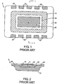
- FIGs. 1 and 2 show that semiconductor package 5 includes MOSFET 10 inside cup-shaped can 12 which functions as a drain clip.
- Can 12 is preferably made from a copper alloy and is silver-plated.
- Can 12 has internal dimensions that are greater than those of MOSFET 10; thus MOSFET 10 is readily received in the interior of can 12.
- the drain contact of MOSFET 10 is connected to the bottom of can 12 by a layer of silver-loaded conductive epoxy 14.
- a ring of low stress high adhesion epoxy 16 is applied around the edges of MOSFET 10 to seal and add extra structural strength to the package.
- Source contact 18 and gate contact 20 of MOSFET 10 which are disposed on a surface of MOSFET 10 opposing its drain contact, are exposed as shown in Fig. 1 .
- Can 12 includes two rows of projections 22 disposed on two of its opposing edges. Projections are provided to make electrical contact with respective lands on a circuit board (not shown), such as an Insulated Metal Substrate or an ordinary circuit board, thereby electrically connecting the drain of MOSFET 10 to its place within a circuit.
- a circuit board not shown
- source contact 18 of MOSFET 10 is flush with the contact surfaces of projections 22 of can 12. Therefore, source contact 18 and gate contact 20 of MOSFET 10 will be flush with the surface of the circuit board when package 5 is mounted thereon.
- Document US-B1-6 262 489 is directed to mounting an IC semiconductor device to a substrate using flip chip technology.
- the assembly generally entails a flip chip having a first surface, an oppositely-disposed second surface, an integrated circuit that includes a vertical device on the first surface, and an electrical contact for the vertical device on the second surface.
- the flip chip is bonded with first solder connections to a first conductor pattern on a substrate, so that the first solder connections electrically and mechanically connect the flip chip to the substrate.
- the assembly further includes an electrical contact member that is positioned so that the flip chip is between the contact member and the substrate.
- the contact member is electrically and mechanically connected to a second conductor pattern on the substrate with second solder connections.
- a third solder connection electrically and mechanically connects the contact member to the electrical contact on the second surface of the flip chip.
- Document US-A-4 392 151 is directed to a semiconductor element disposed in a recess at the bottom of a flanged metallic casing through a solder layer.
- An electrically insulating, molded plate is fixed to the casing by having protrusions fitted into holes disposed in opposite flanges of the casing and also two opposite L-shaped members abutting against adjacent lateral walls of the casing.
- Six strip-shaped leads buried in and extended from the molded plate are arranged to be soldered at first ends to associated solder electrodes on the exposed surface of the semiconductor element.
- the element and L-shaped members are buried in a resinous material molded within the casing.
- the above-described package is subject to possible failure due to temperature cycling, as described above. It is desirable, therefore, to produce a package design having a similar structure as described above, such that substrate failure caused by thermal cycling is reduced.
- a semiconductor device package according to the invention is provided having the features recited in claim 1.
- a semiconductor device package comprising a semiconductor device die having a first surface substantially parallel to a second surface, and the first surface and second surface each have a solderable planar metal electrode.
- a metal clip is disclosed that has a flat web portion comprising a first and second surface, wherein the second surface is electrically connected with the first surface of the semiconductor device die.
- At least one solderable planar metal post-shaped electrode extends over and spaced from an edge of the semiconductor device die.
- the die is disposed in the interior of the clip such that the die is inwardly recessed in the interior of the clip and the second surface of the die is not flush (or co-planar) with the at least one solderable planar metal post-shaped electrode.
- the interior of the solderable planar metal post-shaped electrode is removed to a parallel plane above the plane of the second surface of the die.
- the at least one solderable planar metal post-shaped electrode is mountable to a metallized pattern on a support surface, such as a circuit board and the second surface of the die is spaced from the metallized pattern on the support surface.
- the semiconductor package according to the present invention reduces the number of failures due to thermal cycling and, thus, adds to the reliability of the package. Furthermore, the semiconductor package according to the present invention includes a vertical conduction MOS-gated die such as a MOSFET having a first major surface on which a major electrode and a control electrode are disposed and another major surface opposing the first major surface on which another major electrode is disposed.
- a vertical conduction MOS-gated die such as a MOSFET having a first major surface on which a major electrode and a control electrode are disposed and another major surface opposing the first major surface on which another major electrode is disposed.
- the first major electrode in a vertical conduction MOSFET used in a package according to the present invention is the source electrode; while, its second major electrode is the drain electrode.
- the control electrode in a vertical conduction MOSFET is conventionally referred to as the gate electrode.
- the die is described herein as a power MOSFET, it will be apparent that the die may be any desired die, including any MOS-gated device (e.g., an IGBT), a thyristor or diode, or the like.
- MOS-gated device e.g., an IGBT
- thyristor or diode e.g., a thyristor or diode, or the like.
- Fig. 1 shows a top view of a semiconductor package according to the prior art
- Fig. 2 shows a cross-section of semiconductor package of Fig. 1 looking in the direction of line 1-1;
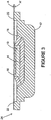
- Fig. 3 shows a cross-section of a semiconductor package of Figs. 1 and 2 modified according to the present invention.
- semiconductor package 24 includes MOSFET 10 that is set back deeper into the interior of can 12 than in prior art packages as shown in Fig.1 and Fig. 2 . Therefore, source contact 18 and gate contact 20 (not shown in Fig. 3 ) of MOSFET 10 are no longer flush with projections 22 of can 12.
- This arrangement is illustrated in Fig. 3 by the gap between broken lines A, A'. It has been found that when MOSFET 10 is set deeper within can 12 such that source 18 is offset from the plane of the circuit board (as represented by broken line A) by about 0.001 - 0.005 inches failure due to thermal cycling of the part when soldered down or affixed by an epoxy to a substrate is reduced.
- a semiconductor package according to the present invention includes a metal can which receives in its interior space a MOSFET or other similar semiconductor type device die.
- the MOSFET so received is inwardly recessed in the can and oriented such that the MOSFET's drain electrode is facing the bottom of the can and is electrically connected to the same by a layer of conductive epoxy or a solder or the like.
- the edges of the MOSFET so placed are spaced from the walls of the can.
- the space between the edges of the MOSFET and the walls of the can is filled with an insulating layer.
- the can preferably includes two rows of posts on its opposing edges.
- the posts are connectable to appropriate conduction pads on a substrate, such as a circuit board, to connect the drain of the MOSFET to its appropriate place within a circuit.
- the posts can be a full or partial portion of the rim of the can.
- the source and gate electrodes of the MOSFET face the substrate when the can is mounted thereon. It has been found that if the MOSFET is positioned within the can so that the source and gate electrodes of the MOSFET become sub-flush with the surface of the substrate, failure due to thermal cycling is improved.
- the bottom surface of the MOSFET is sub-flush below the plane of the substrate by 0.001 - 0.005 inches to reduce temperature cycling failures.
- the sub-flush volume is filled by the conductive attachment material such as solder, epoxy, and the like.
Landscapes
- Engineering & Computer Science (AREA)
- Microelectronics & Electronic Packaging (AREA)
- Computer Hardware Design (AREA)
- Power Engineering (AREA)
- Physics & Mathematics (AREA)
- Condensed Matter Physics & Semiconductors (AREA)
- General Physics & Mathematics (AREA)
- Structures Or Materials For Encapsulating Or Coating Semiconductor Devices Or Solid State Devices (AREA)
- Cooling Or The Like Of Semiconductors Or Solid State Devices (AREA)
- Die Bonding (AREA)
Applications Claiming Priority (5)
| Application Number | Priority Date | Filing Date | Title |
|---|---|---|---|
| US34233301P | 2001-12-21 | 2001-12-21 | |
| US342333P | 2001-12-21 | ||
| US327270 | 2002-12-20 | ||
| US10/327,270 US6930397B2 (en) | 2001-03-28 | 2002-12-20 | Surface mounted package with die bottom spaced from support board |
| PCT/US2002/041477 WO2003060984A1 (en) | 2001-12-21 | 2002-12-23 | Surface mounted package with die bottom spaced from support board |
Related Child Applications (2)
| Application Number | Title | Priority Date | Filing Date |
|---|---|---|---|
| EP17154366.3 Division-Into | 2017-02-02 | ||
| EP17154802.7 Division-Into | 2017-02-06 |
Publications (3)
| Publication Number | Publication Date |
|---|---|
| EP1466357A1 EP1466357A1 (en) | 2004-10-13 |
| EP1466357A4 EP1466357A4 (en) | 2007-08-15 |
| EP1466357B1 true EP1466357B1 (en) | 2017-12-13 |
Family
ID=26985785
Family Applications (1)
| Application Number | Title | Priority Date | Filing Date |
|---|---|---|---|
| EP02797504.4A Expired - Lifetime EP1466357B1 (en) | 2001-12-21 | 2002-12-23 | Surface mounted package with die bottom spaced from support board |
Country Status (6)
| Country | Link |
|---|---|
| US (2) | US6930397B2 (ja) |
| EP (1) | EP1466357B1 (ja) |
| JP (2) | JP4535730B2 (ja) |
| CN (1) | CN100559557C (ja) |
| AU (1) | AU2002361873A1 (ja) |
| WO (1) | WO2003060984A1 (ja) |
Families Citing this family (21)
| Publication number | Priority date | Publication date | Assignee | Title |
|---|---|---|---|---|
| US6930397B2 (en) * | 2001-03-28 | 2005-08-16 | International Rectifier Corporation | Surface mounted package with die bottom spaced from support board |
| JP3879688B2 (ja) * | 2003-03-26 | 2007-02-14 | 株式会社デンソー | 半導体装置 |
| US7786558B2 (en) * | 2005-10-20 | 2010-08-31 | Infineon Technologies Ag | Semiconductor component and methods to produce a semiconductor component |
| US7723830B2 (en) * | 2006-01-06 | 2010-05-25 | International Rectifier Corporation | Substrate and method for mounting silicon device |
| US20070215997A1 (en) * | 2006-03-17 | 2007-09-20 | Martin Standing | Chip-scale package |
| US7663212B2 (en) * | 2006-03-21 | 2010-02-16 | Infineon Technologies Ag | Electronic component having exposed surfaces |
| US7768075B2 (en) | 2006-04-06 | 2010-08-03 | Fairchild Semiconductor Corporation | Semiconductor die packages using thin dies and metal substrates |
| US7541681B2 (en) * | 2006-05-04 | 2009-06-02 | Infineon Technologies Ag | Interconnection structure, electronic component and method of manufacturing the same |
| US7910992B2 (en) | 2008-07-15 | 2011-03-22 | Maxim Integrated Products, Inc. | Vertical MOSFET with through-body via for gate |
| JP5343574B2 (ja) * | 2009-01-20 | 2013-11-13 | トヨタ自動車株式会社 | ヒートシンクのろう付け方法 |
| US8222718B2 (en) * | 2009-02-05 | 2012-07-17 | Fairchild Semiconductor Corporation | Semiconductor die package and method for making the same |
| US8563360B2 (en) * | 2009-06-08 | 2013-10-22 | Alpha And Omega Semiconductor, Inc. | Power semiconductor device package and fabrication method |
| US20110075392A1 (en) | 2009-09-29 | 2011-03-31 | Astec International Limited | Assemblies and Methods for Directly Connecting Integrated Circuits to Electrically Conductive Sheets |
| US7939370B1 (en) * | 2009-10-29 | 2011-05-10 | Alpha And Omega Semiconductor Incorporated | Power semiconductor package |
| US8906747B2 (en) * | 2012-05-23 | 2014-12-09 | Freescale Semiconductor, Inc. | Cavity-type semiconductor package and method of packaging same |
| TW201409752A (zh) * | 2012-08-22 | 2014-03-01 | Phostek Inc | 照明裝置 |
| US9536800B2 (en) | 2013-12-07 | 2017-01-03 | Fairchild Semiconductor Corporation | Packaged semiconductor devices and methods of manufacturing |
| US9214419B2 (en) * | 2014-02-28 | 2015-12-15 | Alpha And Omega Semiconductor Incorporated | Power semiconductor device and preparation method thereof |
| US9117809B1 (en) * | 2014-03-09 | 2015-08-25 | Alpha & Omega Semiconductor (Cayman), Ltd. | Ultra-thin semiconductor device and preparation method thereof |
| CN104979220B (zh) * | 2014-04-02 | 2017-09-01 | 万国半导体股份有限公司 | 功率半导体器件及制备方法 |
| JP6905958B2 (ja) * | 2018-06-27 | 2021-07-21 | 京セラ株式会社 | 接着構造、撮像装置、および移動体 |
Family Cites Families (52)
| Publication number | Priority date | Publication date | Assignee | Title |
|---|---|---|---|---|
| US3403438A (en) | 1964-12-02 | 1968-10-01 | Corning Glass Works | Process for joining transistor chip to printed circuit |
| US3871014A (en) | 1969-08-14 | 1975-03-11 | Ibm | Flip chip module with non-uniform solder wettable areas on the substrate |
| US3972062A (en) | 1973-10-04 | 1976-07-27 | Motorola, Inc. | Mounting assemblies for a plurality of transistor integrated circuit chips |
| GB1487945A (en) | 1974-11-20 | 1977-10-05 | Ibm | Semiconductor integrated circuit devices |
| JPS6020943Y2 (ja) * | 1979-08-29 | 1985-06-22 | 三菱電機株式会社 | 半導体装置 |
| US4604644A (en) | 1985-01-28 | 1986-08-05 | International Business Machines Corporation | Solder interconnection structure for joining semiconductor devices to substrates that have improved fatigue life, and process for making |
| JPH01132142A (ja) * | 1987-08-05 | 1989-05-24 | Mitsubishi Electric Corp | 半導体装置のパツケージ構造 |
| US5047833A (en) | 1990-10-17 | 1991-09-10 | International Rectifier Corporation | Solderable front metal contact for MOS devices |
| JP2984068B2 (ja) | 1991-01-31 | 1999-11-29 | 株式会社日立製作所 | 半導体装置の製造方法 |
| JPH05506545A (ja) * | 1991-02-28 | 1993-09-22 | ゼネラル・エレクトリック・カンパニイ | パワー半導体チップ用の高密度気密パッケージのバッチ式組立 |
| JPH05129516A (ja) | 1991-11-01 | 1993-05-25 | Hitachi Ltd | 半導体装置 |
| CA2089435C (en) | 1992-02-14 | 1997-12-09 | Kenzi Kobayashi | Semiconductor device |
| JP2833326B2 (ja) | 1992-03-03 | 1998-12-09 | 松下電器産業株式会社 | 電子部品実装接続体およびその製造方法 |
| JPH0637143A (ja) | 1992-07-15 | 1994-02-10 | Toshiba Corp | 半導体装置および半導体装置の製造方法 |
| US5394490A (en) | 1992-08-11 | 1995-02-28 | Hitachi, Ltd. | Semiconductor device having an optical waveguide interposed in the space between electrode members |
| US5313366A (en) | 1992-08-12 | 1994-05-17 | International Business Machines Corporation | Direct chip attach module (DCAM) |
| JPH06244231A (ja) | 1993-02-01 | 1994-09-02 | Motorola Inc | 気密半導体デバイスおよびその製造方法 |
| US5371404A (en) | 1993-02-04 | 1994-12-06 | Motorola, Inc. | Thermally conductive integrated circuit package with radio frequency shielding |
| JP2795788B2 (ja) | 1993-02-18 | 1998-09-10 | シャープ株式会社 | 半導体チップの実装方法 |
| US5703405A (en) | 1993-03-15 | 1997-12-30 | Motorola, Inc. | Integrated circuit chip formed from processing two opposing surfaces of a wafer |
| US5510758A (en) | 1993-04-07 | 1996-04-23 | Matsushita Electric Industrial Co., Ltd. | Multilayer microstrip wiring board with a semiconductor device mounted thereon via bumps |
| JP3258764B2 (ja) | 1993-06-01 | 2002-02-18 | 三菱電機株式会社 | 樹脂封止型半導体装置の製造方法ならびに外部引出用電極およびその製造方法 |
| US5397921A (en) | 1993-09-03 | 1995-03-14 | Advanced Semiconductor Assembly Technology | Tab grid array |
| US5734201A (en) | 1993-11-09 | 1998-03-31 | Motorola, Inc. | Low profile semiconductor device with like-sized chip and mounting substrate |
| US5367435A (en) | 1993-11-16 | 1994-11-22 | International Business Machines Corporation | Electronic package structure and method of making same |
| US5454160A (en) | 1993-12-03 | 1995-10-03 | Ncr Corporation | Apparatus and method for stacking integrated circuit devices |
| JPH07193184A (ja) | 1993-12-27 | 1995-07-28 | Fujitsu Ltd | マルチチップモジュールの製造方法及びマルチチップモジュール |
| US5446316A (en) * | 1994-01-06 | 1995-08-29 | Harris Corporation | Hermetic package for a high power semiconductor device |
| US5578869A (en) | 1994-03-29 | 1996-11-26 | Olin Corporation | Components for housing an integrated circuit device |
| JP3377867B2 (ja) | 1994-08-12 | 2003-02-17 | 京セラ株式会社 | 半導体素子収納用パッケージ |
| JP2546192B2 (ja) | 1994-09-30 | 1996-10-23 | 日本電気株式会社 | フィルムキャリア半導体装置 |
| US5532512A (en) | 1994-10-03 | 1996-07-02 | General Electric Company | Direct stacked and flip chip power semiconductor device structures |
| JP3138159B2 (ja) | 1994-11-22 | 2001-02-26 | シャープ株式会社 | 半導体装置、半導体装置実装体、及び半導体装置の交換方法 |
| US5904499A (en) | 1994-12-22 | 1999-05-18 | Pace; Benedict G | Package for power semiconductor chips |
| JPH08335653A (ja) | 1995-04-07 | 1996-12-17 | Nitto Denko Corp | 半導体装置およびその製法並びに上記半導体装置の製造に用いる半導体装置用テープキャリア |
| US5655703A (en) | 1995-05-25 | 1997-08-12 | International Business Machines Corporation | Solder hierarchy for chip attachment to substrates |
| US5674785A (en) | 1995-11-27 | 1997-10-07 | Micron Technology, Inc. | Method of producing a single piece package for semiconductor die |
| US5726502A (en) | 1996-04-26 | 1998-03-10 | Motorola, Inc. | Bumped semiconductor device with alignment features and method for making the same |
| JPH11510666A (ja) * | 1996-05-24 | 1999-09-14 | シーメンス マツシタ コンポーネンツ ゲゼルシヤフト ミツト ベシユレンクテル ハフツング ウント コンパニコマンデイート ゲゼルシヤフト | 電子デバイス、特に表面音波で作動するデバイス―sawデバイス |
| US5814884C1 (en) | 1996-10-24 | 2002-01-29 | Int Rectifier Corp | Commonly housed diverse semiconductor die |
| US6133634A (en) | 1998-08-05 | 2000-10-17 | Fairchild Semiconductor Corporation | High performance flip chip package |
| US6396127B1 (en) * | 1998-09-25 | 2002-05-28 | International Rectifier Corporation | Semiconductor package |
| KR20000057810A (ko) * | 1999-01-28 | 2000-09-25 | 가나이 쓰토무 | 반도체 장치 |
| US6262489B1 (en) | 1999-11-08 | 2001-07-17 | Delphi Technologies, Inc. | Flip chip with backside electrical contact and assembly and method therefor |
| US6744124B1 (en) | 1999-12-10 | 2004-06-01 | Siliconix Incorporated | Semiconductor die package including cup-shaped leadframe |
| US6624522B2 (en) * | 2000-04-04 | 2003-09-23 | International Rectifier Corporation | Chip scale surface mounted device and process of manufacture |
| US6391687B1 (en) | 2000-10-31 | 2002-05-21 | Fairchild Semiconductor Corporation | Column ball grid array package |
| US6777786B2 (en) * | 2001-03-12 | 2004-08-17 | Fairchild Semiconductor Corporation | Semiconductor device including stacked dies mounted on a leadframe |
| US6930397B2 (en) * | 2001-03-28 | 2005-08-16 | International Rectifier Corporation | Surface mounted package with die bottom spaced from support board |
| US6469398B1 (en) * | 2001-03-29 | 2002-10-22 | Kabushiki Kaisha Toshiba | Semiconductor package and manufacturing method thereof |
| US6784540B2 (en) * | 2001-10-10 | 2004-08-31 | International Rectifier Corp. | Semiconductor device package with improved cooling |
| US6841865B2 (en) * | 2002-11-22 | 2005-01-11 | International Rectifier Corporation | Semiconductor device having clips for connecting to external elements |
-
2002
- 2002-12-20 US US10/327,270 patent/US6930397B2/en not_active Expired - Lifetime
- 2002-12-23 CN CNB028252802A patent/CN100559557C/zh not_active Expired - Fee Related
- 2002-12-23 AU AU2002361873A patent/AU2002361873A1/en not_active Abandoned
- 2002-12-23 JP JP2003560978A patent/JP4535730B2/ja not_active Expired - Fee Related
- 2002-12-23 EP EP02797504.4A patent/EP1466357B1/en not_active Expired - Lifetime
- 2002-12-23 WO PCT/US2002/041477 patent/WO2003060984A1/en active Application Filing
-
2005
- 2005-06-07 US US11/146,628 patent/US7285866B2/en not_active Expired - Lifetime
-
2007
- 2007-08-17 JP JP2007212938A patent/JP2007295014A/ja active Pending
Also Published As
| Publication number | Publication date |
|---|---|
| WO2003060984A1 (en) | 2003-07-24 |
| US7285866B2 (en) | 2007-10-23 |
| US20050224960A1 (en) | 2005-10-13 |
| EP1466357A1 (en) | 2004-10-13 |
| CN100559557C (zh) | 2009-11-11 |
| JP4535730B2 (ja) | 2010-09-01 |
| CN1605121A (zh) | 2005-04-06 |
| EP1466357A4 (en) | 2007-08-15 |
| JP2007295014A (ja) | 2007-11-08 |
| JP2005515635A (ja) | 2005-05-26 |
| AU2002361873A1 (en) | 2003-07-30 |
| US6930397B2 (en) | 2005-08-16 |
| US20030132531A1 (en) | 2003-07-17 |
Similar Documents
| Publication | Publication Date | Title |
|---|---|---|
| EP1466357B1 (en) | Surface mounted package with die bottom spaced from support board | |
| US4340902A (en) | Semiconductor device | |
| US6421244B1 (en) | Power module | |
| US5777386A (en) | Semiconductor device and mount structure thereof | |
| US5398160A (en) | Compact power module with a heat spreader | |
| US5311060A (en) | Heat sink for semiconductor device assembly | |
| KR100714917B1 (ko) | 차폐판이 개재된 칩 적층 구조 및 그를 갖는 시스템 인패키지 | |
| US4554613A (en) | Multiple substrate circuit package | |
| KR100229858B1 (ko) | 반도체 장치 | |
| EP3929973B1 (en) | A power semiconductor module and a method for producing a power semiconductor module | |
| US20050280018A1 (en) | Light-emitting diode | |
| JPH08148839A (ja) | 混成集積回路装置 | |
| EP1887635B1 (en) | Light-emitting device | |
| JPH09199629A (ja) | 半導体装置 | |
| EP0942635B1 (en) | A power semiconductor device for "flip-chip" connections | |
| KR20000028805A (ko) | 하이브리드 모듈 | |
| EP3863045A1 (en) | Power semiconductor module arrangement and method for producing the same | |
| KR102552424B1 (ko) | 반도체 패키지 | |
| JPH07226454A (ja) | 半導体装置 | |
| JP3714808B2 (ja) | 半導体装置 | |
| JPS63107126A (ja) | 半導体装置 | |
| CN114556554A (zh) | 基板、封装结构及电子设备 | |
| KR20020069128A (ko) | 반도체장치와 이에 이용되는 지지기판 | |
| CN114334846A (zh) | 功率器件封装装置及方法 | |
| CN115579346A (zh) | 功率模块的连接结构、封装结构以及制作工艺 |
Legal Events
| Date | Code | Title | Description |
|---|---|---|---|
| PUAI | Public reference made under article 153(3) epc to a published international application that has entered the european phase |
Free format text: ORIGINAL CODE: 0009012 |
|
| 17P | Request for examination filed |
Effective date: 20040713 |
|
| AK | Designated contracting states |
Kind code of ref document: A1 Designated state(s): AT BE BG CH CY CZ DE DK EE ES FI FR GB GR IE IT LI LU MC NL PT SE SI SK TR |
|
| AX | Request for extension of the european patent |
Extension state: AL LT LV MK RO |
|
| A4 | Supplementary search report drawn up and despatched |
Effective date: 20070712 |
|
| RIC1 | Information provided on ipc code assigned before grant |
Ipc: H01L 21/44 20060101AFI20030729BHEP Ipc: H01L 23/047 20060101ALI20070707BHEP |
|
| 17Q | First examination report despatched |
Effective date: 20090121 |
|
| APBK | Appeal reference recorded |
Free format text: ORIGINAL CODE: EPIDOSNREFNE |
|
| APBN | Date of receipt of notice of appeal recorded |
Free format text: ORIGINAL CODE: EPIDOSNNOA2E |
|
| APBR | Date of receipt of statement of grounds of appeal recorded |
Free format text: ORIGINAL CODE: EPIDOSNNOA3E |
|
| APAF | Appeal reference modified |
Free format text: ORIGINAL CODE: EPIDOSCREFNE |
|
| APBT | Appeal procedure closed |
Free format text: ORIGINAL CODE: EPIDOSNNOA9E |
|
| GRAP | Despatch of communication of intention to grant a patent |
Free format text: ORIGINAL CODE: EPIDOSNIGR1 |
|
| INTG | Intention to grant announced |
Effective date: 20170412 |
|
| GRAS | Grant fee paid |
Free format text: ORIGINAL CODE: EPIDOSNIGR3 |
|
| GRAA | (expected) grant |
Free format text: ORIGINAL CODE: 0009210 |
|
| RAP1 | Party data changed (applicant data changed or rights of an application transferred) |
Owner name: INFINEON TECHNOLOGIES AMERICAS CORP. |
|
| AK | Designated contracting states |
Kind code of ref document: B1 Designated state(s): AT BE BG CH CY CZ DE DK EE ES FI FR GB GR IE IT LI LU MC NL PT SE SI SK TR |
|
| REG | Reference to a national code |
Ref country code: GB Ref legal event code: FG4D |
|
| REG | Reference to a national code |
Ref country code: AT Ref legal event code: REF Ref document number: 955144 Country of ref document: AT Kind code of ref document: T Effective date: 20171215 Ref country code: CH Ref legal event code: EP |
|
| REG | Reference to a national code |
Ref country code: IE Ref legal event code: FG4D |
|
| REG | Reference to a national code |
Ref country code: DE Ref legal event code: R096 Ref document number: 60249212 Country of ref document: DE |
|
| PG25 | Lapsed in a contracting state [announced via postgrant information from national office to epo] |
Ref country code: SE Free format text: LAPSE BECAUSE OF FAILURE TO SUBMIT A TRANSLATION OF THE DESCRIPTION OR TO PAY THE FEE WITHIN THE PRESCRIBED TIME-LIMIT Effective date: 20171213 Ref country code: FI Free format text: LAPSE BECAUSE OF FAILURE TO SUBMIT A TRANSLATION OF THE DESCRIPTION OR TO PAY THE FEE WITHIN THE PRESCRIBED TIME-LIMIT Effective date: 20171213 |
|
| REG | Reference to a national code |
Ref country code: AT Ref legal event code: MK05 Ref document number: 955144 Country of ref document: AT Kind code of ref document: T Effective date: 20171213 |
|
| PG25 | Lapsed in a contracting state [announced via postgrant information from national office to epo] |
Ref country code: GR Free format text: LAPSE BECAUSE OF FAILURE TO SUBMIT A TRANSLATION OF THE DESCRIPTION OR TO PAY THE FEE WITHIN THE PRESCRIBED TIME-LIMIT Effective date: 20180314 Ref country code: BG Free format text: LAPSE BECAUSE OF FAILURE TO SUBMIT A TRANSLATION OF THE DESCRIPTION OR TO PAY THE FEE WITHIN THE PRESCRIBED TIME-LIMIT Effective date: 20180313 |
|
| PG25 | Lapsed in a contracting state [announced via postgrant information from national office to epo] |
Ref country code: NL Free format text: LAPSE BECAUSE OF FAILURE TO SUBMIT A TRANSLATION OF THE DESCRIPTION OR TO PAY THE FEE WITHIN THE PRESCRIBED TIME-LIMIT Effective date: 20171213 |
|
| PG25 | Lapsed in a contracting state [announced via postgrant information from national office to epo] |
Ref country code: SK Free format text: LAPSE BECAUSE OF FAILURE TO SUBMIT A TRANSLATION OF THE DESCRIPTION OR TO PAY THE FEE WITHIN THE PRESCRIBED TIME-LIMIT Effective date: 20171213 Ref country code: CY Free format text: LAPSE BECAUSE OF FAILURE TO SUBMIT A TRANSLATION OF THE DESCRIPTION OR TO PAY THE FEE WITHIN THE PRESCRIBED TIME-LIMIT Effective date: 20171213 Ref country code: EE Free format text: LAPSE BECAUSE OF FAILURE TO SUBMIT A TRANSLATION OF THE DESCRIPTION OR TO PAY THE FEE WITHIN THE PRESCRIBED TIME-LIMIT Effective date: 20171213 Ref country code: ES Free format text: LAPSE BECAUSE OF FAILURE TO SUBMIT A TRANSLATION OF THE DESCRIPTION OR TO PAY THE FEE WITHIN THE PRESCRIBED TIME-LIMIT Effective date: 20171213 Ref country code: CZ Free format text: LAPSE BECAUSE OF FAILURE TO SUBMIT A TRANSLATION OF THE DESCRIPTION OR TO PAY THE FEE WITHIN THE PRESCRIBED TIME-LIMIT Effective date: 20171213 |
|
| REG | Reference to a national code |
Ref country code: CH Ref legal event code: PL |
|
| PG25 | Lapsed in a contracting state [announced via postgrant information from national office to epo] |
Ref country code: AT Free format text: LAPSE BECAUSE OF FAILURE TO SUBMIT A TRANSLATION OF THE DESCRIPTION OR TO PAY THE FEE WITHIN THE PRESCRIBED TIME-LIMIT Effective date: 20171213 Ref country code: IT Free format text: LAPSE BECAUSE OF FAILURE TO SUBMIT A TRANSLATION OF THE DESCRIPTION OR TO PAY THE FEE WITHIN THE PRESCRIBED TIME-LIMIT Effective date: 20171213 |
|
| REG | Reference to a national code |
Ref country code: DE Ref legal event code: R097 Ref document number: 60249212 Country of ref document: DE |
|
| REG | Reference to a national code |
Ref country code: IE Ref legal event code: MM4A |
|
| PG25 | Lapsed in a contracting state [announced via postgrant information from national office to epo] |
Ref country code: MC Free format text: LAPSE BECAUSE OF FAILURE TO SUBMIT A TRANSLATION OF THE DESCRIPTION OR TO PAY THE FEE WITHIN THE PRESCRIBED TIME-LIMIT Effective date: 20171213 Ref country code: LU Free format text: LAPSE BECAUSE OF NON-PAYMENT OF DUE FEES Effective date: 20171223 |
|
| REG | Reference to a national code |
Ref country code: BE Ref legal event code: MM Effective date: 20171231 |
|
| PLBE | No opposition filed within time limit |
Free format text: ORIGINAL CODE: 0009261 |
|
| STAA | Information on the status of an ep patent application or granted ep patent |
Free format text: STATUS: NO OPPOSITION FILED WITHIN TIME LIMIT |
|
| PG25 | Lapsed in a contracting state [announced via postgrant information from national office to epo] |
Ref country code: IE Free format text: LAPSE BECAUSE OF NON-PAYMENT OF DUE FEES Effective date: 20171223 |
|
| REG | Reference to a national code |
Ref country code: FR Ref legal event code: ST Effective date: 20181008 |
|
| 26N | No opposition filed |
Effective date: 20180914 |
|
| GBPC | Gb: european patent ceased through non-payment of renewal fee |
Effective date: 20180313 |
|
| PG25 | Lapsed in a contracting state [announced via postgrant information from national office to epo] |
Ref country code: LI Free format text: LAPSE BECAUSE OF NON-PAYMENT OF DUE FEES Effective date: 20171231 Ref country code: CH Free format text: LAPSE BECAUSE OF NON-PAYMENT OF DUE FEES Effective date: 20171231 Ref country code: DK Free format text: LAPSE BECAUSE OF FAILURE TO SUBMIT A TRANSLATION OF THE DESCRIPTION OR TO PAY THE FEE WITHIN THE PRESCRIBED TIME-LIMIT Effective date: 20171213 Ref country code: BE Free format text: LAPSE BECAUSE OF NON-PAYMENT OF DUE FEES Effective date: 20171231 |
|
| PG25 | Lapsed in a contracting state [announced via postgrant information from national office to epo] |
Ref country code: GB Free format text: LAPSE BECAUSE OF NON-PAYMENT OF DUE FEES Effective date: 20180313 Ref country code: SI Free format text: LAPSE BECAUSE OF FAILURE TO SUBMIT A TRANSLATION OF THE DESCRIPTION OR TO PAY THE FEE WITHIN THE PRESCRIBED TIME-LIMIT Effective date: 20171213 Ref country code: FR Free format text: LAPSE BECAUSE OF NON-PAYMENT OF DUE FEES Effective date: 20180213 |
|
| PG25 | Lapsed in a contracting state [announced via postgrant information from national office to epo] |
Ref country code: TR Free format text: LAPSE BECAUSE OF FAILURE TO SUBMIT A TRANSLATION OF THE DESCRIPTION OR TO PAY THE FEE WITHIN THE PRESCRIBED TIME-LIMIT Effective date: 20171213 |
|
| PGFP | Annual fee paid to national office [announced via postgrant information from national office to epo] |
Ref country code: DE Payment date: 20200224 Year of fee payment: 18 |
|
| PG25 | Lapsed in a contracting state [announced via postgrant information from national office to epo] |
Ref country code: PT Free format text: LAPSE BECAUSE OF FAILURE TO SUBMIT A TRANSLATION OF THE DESCRIPTION OR TO PAY THE FEE WITHIN THE PRESCRIBED TIME-LIMIT Effective date: 20171213 |
|
| REG | Reference to a national code |
Ref country code: DE Ref legal event code: R119 Ref document number: 60249212 Country of ref document: DE |
|
| PG25 | Lapsed in a contracting state [announced via postgrant information from national office to epo] |
Ref country code: DE Free format text: LAPSE BECAUSE OF NON-PAYMENT OF DUE FEES Effective date: 20210701 |