EP1465135A1 - System und Verfahren zur Fahrerunterstützung - Google Patents
System und Verfahren zur Fahrerunterstützung Download PDFInfo
- Publication number
- EP1465135A1 EP1465135A1 EP04015913A EP04015913A EP1465135A1 EP 1465135 A1 EP1465135 A1 EP 1465135A1 EP 04015913 A EP04015913 A EP 04015913A EP 04015913 A EP04015913 A EP 04015913A EP 1465135 A1 EP1465135 A1 EP 1465135A1
- Authority
- EP
- European Patent Office
- Prior art keywords
- vehicle
- driving operation
- image
- movement pattern
- prescribed movement
- Prior art date
- Legal status (The legal status is an assumption and is not a legal conclusion. Google has not performed a legal analysis and makes no representation as to the accuracy of the status listed.)
- Withdrawn
Links
Images


Classifications
-
- B—PERFORMING OPERATIONS; TRANSPORTING
- B62—LAND VEHICLES FOR TRAVELLING OTHERWISE THAN ON RAILS
- B62D—MOTOR VEHICLES; TRAILERS
- B62D15/00—Steering not otherwise provided for
- B62D15/02—Steering position indicators ; Steering position determination; Steering aids
- B62D15/027—Parking aids, e.g. instruction means
- B62D15/0285—Parking performed automatically
-
- G—PHYSICS
- G08—SIGNALLING
- G08G—TRAFFIC CONTROL SYSTEMS
- G08G1/00—Traffic control systems for road vehicles
- G08G1/16—Anti-collision systems
- G08G1/161—Decentralised systems, e.g. inter-vehicle communication
-
- G—PHYSICS
- G08—SIGNALLING
- G08G—TRAFFIC CONTROL SYSTEMS
- G08G1/00—Traffic control systems for road vehicles
- G08G1/16—Anti-collision systems
- G08G1/165—Anti-collision systems for passive traffic, e.g. including static obstacles, trees
-
- G—PHYSICS
- G08—SIGNALLING
- G08G—TRAFFIC CONTROL SYSTEMS
- G08G1/00—Traffic control systems for road vehicles
- G08G1/16—Anti-collision systems
- G08G1/168—Driving aids for parking, e.g. acoustic or visual feedback on parking space
-
- B—PERFORMING OPERATIONS; TRANSPORTING
- B60—VEHICLES IN GENERAL
- B60T—VEHICLE BRAKE CONTROL SYSTEMS OR PARTS THEREOF; BRAKE CONTROL SYSTEMS OR PARTS THEREOF, IN GENERAL; ARRANGEMENT OF BRAKING ELEMENTS ON VEHICLES IN GENERAL; PORTABLE DEVICES FOR PREVENTING UNWANTED MOVEMENT OF VEHICLES; VEHICLE MODIFICATIONS TO FACILITATE COOLING OF BRAKES
- B60T2201/00—Particular use of vehicle brake systems; Special systems using also the brakes; Special software modules within the brake system controller
- B60T2201/10—Automatic or semi-automatic parking aid systems
Definitions
- the present invention relates to a driving operation assisting technique for providing an assistance in a vehicle driving operation.
- a common driving operation assisting system in the prior art uses a steering sensor for detecting the rudder angle of the steering wheel so as to estimate the vehicle tire (movement) trace according to the rudder angle of the steering wheel when moving the vehicle backward (see Japanese Laid-Open Patent Publication No. 1-14700).
- the rear view or the rearside view is imaged by a camera and displayed, while the vehicle tire trace which is estimated according to the rudder angle of the steering wheel being operated is superimposed on the image.
- the driving operation is as follows. That is, first, the vehicle is moved to a position where it is likely to be possible to move the vehicle into a parking space with the steering wheel being fixed. Then, in this position, the user operates the steering wheel while viewing the estimated vehicle tire trace so as to find a rudder angle at which it is likely to be possible to move the vehicle into the parking space without having to further operate the steering wheel. Then, the vehicle is moved backward while keeping the rudder angle so as to move the vehicle into the parking space. In principle, the parking operation is completed through such a driving operation.
- the driver moves the vehicle from the start position to the parking position as follows. The driver first turns the steering wheel in an appropriate direction and moves the vehicle backward, and after the vehicle is moved backward to an appropriate position, the driver turns the steering wheel in the opposite direction to move the vehicle to the target position. In other words, in the case of parallel parking, it is difficult to park the vehicle while keeping the steering rudder angle at a constant angle.
- An object of the present invention is to provide a driving operation assisting technique so as to further improve the user's convenience and reduce the user's burden with.
- the present invention provides a method for providing an assistance in a vehicle driving operation by displaying an image representing surrounding conditions around the vehicle on a display unit, the method including: a first step of allowing a user to specify, on the image on the display unit, an end position which is a position of the vehicle at an end of a predetermined driving operation; a second step of obtaining, for the end position, a start position which is a position of the vehicle at a start of the predetermined driving operation according to a prescribed movement pattern representing a movement of the vehicle in the predetermined driving operation.
- the start position of the driving operation can be automatically obtained, thereby reducing the amount of time required before starting the driving operation.
- the driving operation assisting method of the present invention further includes a step of displaying the start position, the end position and the prescribed movement pattern while being superimposed on the image on the display unit. Accordingly, whether the start position or the prescribed movement pattern interferes with an obstacle can be easily recognized on a screen.
- the end position specified by the user is taken as an input when the vehicle is in a vicinity of the end position.
- the end position is taken as an input when the vehicle is in a vicinity of the end position.
- the driving operation assigning method of the present invention further includes a step of performing, in a full-automatic or semi-automatic manner, at least one of an operation of driving the vehicle from a current position of the vehicle to the start position and an operation of driving the vehicle from the start position to the end position according to the prescribed movement pattern.
- the present invention provides a system for providing an assistance in a vehicle driving operation, the system including: surrounding condition imaging means for producing an image representing surrounding conditions around the vehicle; prescribed movement pattern storage means for storing a prescribed movement pattern representing a movement of the vehicle in a predetermined driving operation; synthesized image production means for producing a synthesized image by superimposing the prescribed movement pattern on the surrounding condition image; a display unit for displaying the synthesized image; and pattern selection means for selecting the prescribed movement pattern based on a pointer input operation on a screen of the display unit.
- a prescribed trace of the vehicle can be input through a pointer input operation on the screen of the display unit, thereby significantly facilitating the selection of the prescribed movement pattern.
- the present invention provides a system for providing an assistance in a vehicle driving operation, the system including an image processing section for producing an image representing surrounding conditions around the vehicle, wherein the image processing section produces a synthesized image by superimposing, on the surrounding condition image, a circumscribed area trace of space where the vehicle passes as the vehicle is moved by a predetermined driving operation.
- the circumscribed area trace of space where the entire vehicle passes is displayed as an image, whereby the user can more precisely determine whether a part of the vehicle, such as a bumper, which extends beyond the tire will contact an obstacle.
- the image processing section produces the surrounding condition image by synthesizing images output from a plurality of cameras provided on the vehicle.
- FIG. 1 is a block diagram illustrating a configuration of a driving operation assisting system according to the first embodiment of the present invention.
- the driving operation assisting system of the present embodiment primarily aims to provide an assistance in a driving operation such as perpendicular parking, parallel parking, and the like.
- the driving operation assisting system of the present embodiment includes: an imaging section 101 having N cameras (cameras C1 to CN); a camera parameter table 103 for storing camera parameters representing the characteristics of the cameras C1 to CN; space reconstruction means 104 for producing space data in which the respective pixels forming the output images from the cameras C1 to CN are correlated to points in a three-dimensional space based on the camera parameters; viewpoint conversion means 106 for producing, as a surrounding condition image, an image as viewed from a predetermined viewpoint by referencing the space data; a space data buffer 105 for temporarily storing the space data; prescribed movement pattern storage means 108 for storing prescribed movement data including prescribed movement patterns; superimposition means 102 for producing a synthesized image by superimposing the prescribed movement pattern on the surrounding condition image; and a display unit 107 for displaying the synthesized image.
- the driving operation assisting system includes end position input means 201 , start position determination means 202 , and space fixing means 203 .
- the end position input means 201 is used to input with a pointer the target position, i.e., the end position, of the driving operation. Note that the end position may alternatively be input through a numeric input operation, etc.
- the start position determination means 202 obtains the start position of the driving operation for the end position which is input through the end position input means 201 , based on the prescribed movement pattern corresponding to the driving operation.
- the space fixing means 203 fixes the prescribed movement pattern for the driving operation in the surrounding space of the synthesized image after the end position is specified through the end position input means 201 .
- the prescribed movement pattern may be fixed by following characteristic points in camera images or to calculate the movement of the vehicle based on the actual steering angle or tire rotation of the vehicle so as to modify the movement of the surrounding space of the image by the movement.
- FIG. 2 is a diagram illustrating an exemplary arrangement of the cameras C1 to CN of the imaging section 101 on a vehicle 1.
- N 6
- six cameras C1 to C6 are arranged on the roof of the vehicle 1 .
- the cameras C1 to C6 are arranged so that the imaging range of one camera partially overlaps with the imaging range of another camera and that the entire imaging range has no dead angle in a plan view.
- the camera parameter table 103 stores camera parameters (the attachment position, the attachment angle, the lens distortion correction value, the focal distance of the lens, etc.) representing the camera characteristics of the cameras C1 to CN.
- the space reconstruction means 104 produces space data in which the respective pixels forming the output images from the cameras C1 to CN are correlated to points in a three-dimensional space with respect to the vehicle based on the camera parameters.
- the space data is temporarily stored in the space data buffer 105 , and the viewpoint conversion means 106 produces, as the surrounding condition image, an image as viewed from an arbitrary viewpoint, e.g., the viewpoint of a virtual camera VC illustrated in FIG. 3 , by synthesizing the respective pixels by referencing the space data.
- FIG. 4 illustrates an exemplary surrounding condition image as viewed from the viewpoint of the virtual camera VC illustrated in FIG. 3 .
- the example of FIG. 4 is a case of parallel parking, wherein two parked vehicles are shown on the surrounding condition image as obstacles OB1 and OB2.
- the prescribed movement pattern storage means 108 stores as prescribed movement data: prescribed movement patterns each of which is image data representing the movement of the vehicle when performing a typical driving operation; and chronological data representing the relationship between the traveling distance of the vehicle (the amount of rotational movement of the tires) and the steering rudder angle (the steering angle) for each of the prescribed movement patterns.
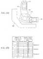
- FIG. 5A and FIG. 5B are diagrams illustrating exemplary prescribed movement data when performing a driving operation of parallel parking to the left side
- FIG. 6A and FIG. 6B are diagrams illustrating exemplary prescribed movement data when performing a driving operation of perpendicular parking to the right side
- FIG. 5A and FIG. 6A each illustrate a prescribed movement pattern, which is image data representing an operation start position ST1, ST2, an operation end position EN1, EN2, and a tire trace TR1, TR2 when performing the driving operation according to the chronological data illustrated in FIG. 5B and FIG. 6B, respectively.
- the user selects one of the prescribed movement patterns stored in the prescribed movement pattern storage means 108 by using pattern selection means (not shown).
- the superimposition means 102 produces a synthesized image by superimposing the selected prescribed movement pattern (e.g., FIG. 5A ) on the surrounding condition image produced by the viewpoint conversion means 106 (e.g., FIG. 4 ).
- the display unit 107 displays the synthesized image.
- the operation start position ST1 of FIG. 5A for example, is aligned with the current position of the vehicle, the operation end position EN1 is the parking position, i.e., the operation end position in a case where the driving operation corresponding to the prescribed movement pattern is started from the current position.
- FIG. 7 is a diagram illustrating an exemplary s ynthesized image obtained by synthesizing the prescribed movement pattern illustrated in FIG. 5A and FIG. 5B
- FIG. 8 is a diagram illustrating an exemplary synthesized image obtained by synthesizing the prescribed movement pattern illustrated in FIG. 6A and FIG. 6B .
- the driver moves the vehicle to a start position STA such that a parking position PAA ( EN1 ), the tire trace TR1 and the start position STA ( ST1 ) do not interfere with the obstacles OB1 and OB2. Then, the driver can perform parallel parking to the left side to park the vehicle into the parking position PAA by starting a series of driving operations according to the chronological data illustrated in FIG. 5B from the start position STA.
- the driver moves the vehicle to a start position STB such that a parking position PAB ( EN2 ), the tire trace TR2 and the start position STB ( ST2 ) do not interfere with obstacles OB3 and OB4 .
- the driver can perform perpendicular parking to the right side to park the vehicle into the parking position PAB by starting a series of driving operations from the start position STB according to the chronological data shown in FIG. 6B.
- FIG. 9 is a diagram illustrating the movement of the vehicle when performing parallel parking to the left side.
- the driver of the vehicle in order to park the vehicle into the target parking position PAA, the driver of the vehicle first needs to move the vehicle which is located at a current position CP to the target start position STA .
- the target start position STA corresponds to the operation start position ST1 with the operation end position EN1 of the prescribed movement pattern of performing parallel parking to the left side as illustrated in FIG. 5A being aligned with the target parking position PAA.
- the positional relationship between the operation end position EN1 and the operation start position ST1 in the prescribed movement pattern illustrated in FIG. 5A corresponds to the case where a driving operation is performed according to the chronological data illustrated in FIG. 5B.
- fine adjustments can be made by, for example, slightly turning the steering wheel, etc.
- the driver needs to do checking from the inside of the vehicle through direct viewing, looking in a mirror, etc., so as to recognize the obstacles OB1 and OB2, and to move the vehicle to the target start position STA while paying attention to the target parking position PAA .
- Such a task requires a considerable amount of practice.
- the driver cannot immediately adapt to the changes.
- images obtained by the cameras mounted on the vehicle are used to produce a surrounding condition image as illustrated in FIG. 4 which looks as if it were taken from above the vehicle, and a prescribed movement pattern as illustrated in FIG. 5A is superimposed thereon, so as to display a synthesized image as illustrated in FIG. 7 to the driver.
- the prescribed movement pattern as illustrated in FIG. 5A is displayed while the current position CP of the vehicle and the operation start position ST1 are aligned with each other, as illustrated in FIG. 10A to FIG. 10C.
- the operation end position EN1 is displayed as a parking position PA1 corresponding to the current position CP , with the operation start position ST1 being the current position CP.
- the parking position PA1 overlaps with the obstacle OB2. Therefore, the driver can determine at a glance that the vehicle may possibly contact the obstacle OB2 if the driver starts the parking operation from the current position CP. Thus, the driver can easily recognize that the driver needs to further move the vehicle forward (upward in FIG. 10A to FIG. 10C ) before starting the parking operation.
- the tire trace TR1 overlaps with the obstacle OB1. Therefore, the driver can determine at a glance that the vehicle may possibly contact the obstacle OB1 if the driver starts the parking operation from the current position CP . Thus, the driver can easily recognize that the driver needs to further move the vehicle backward (downward in FIG. 10A to FIG. 10C) before starting the parking operation.
- the driver can determine at a glance the positional relationship.
- the driver can determine at a glance the suitable position from which to start the parking operation, and can move the vehicle to such a position before starting the parking operation, whereby it is possible to park the vehicle into the intended position in a safer and more reliable manner.
- the operation start position, the operation end position and the tire trace, which represent the prescribed movement pattern, are inherent to each vehicle, and significantly differ between a small vehicle and a large vehicle, for example. This can be addressed by storing different prescribed movement patterns for different vehicles in the prescribed movement pattern storage means 108 of FIG. 1 . Then, even when driving a different vehicle, the driver can perform the driving operation while viewing the positional relationship between a prescribed movement pattern and the surrounding obstacles, etc., for that vehicle.
- the arrangement and/or the number of the on-vehicle cameras as illustrated in FIG. 2 may change from one vehicle to another.
- this can also be addressed by storing, in the camera parameter table 103 , the camera parameters of the cameras for each vehicle, and does not directly influence the image displayed to the driver. Therefore, even when the camera arrangement changes for a different vehicle, the driver can perform a driving operation while viewing the positional relationship between a prescribed movement pattern and the surrounding obstacles, etc., for that vehicle, which is displayed in substantially the same manner as when the driver was driving the previous vehicle.
- the driver can perform a driving operation while viewing the positional relationship between a prescribed movement pattern and the surrounding obstacles, etc., for that vehicle, in a similar manner as when the driver was driving the previous vehicle. Therefore, it is possible to significantly reduce the practice burden which is otherwise imposed on the driver when the driver changes a vehicle to another.
- FIG. 11 is a diagram illustrating exemplary variations of prescribed movement patterns stored in the prescribed movement pattern storage means 108 of FIG. 1 .
- FIG. 11 illustrates prescribed movement patterns PT1 and PT2 for parallel parking to the left side and to the right side, respectively, and prescribed movement patterns PT3 and PT4 for perpendicular parking to the left side and to the right side, respectively.
- the driver selects one of the prescribed movement patterns PT1 to PT4 by using the pattern selection means (not shown), and the area to be displayed as a synthesized image (shown as a frame in FIG. 11 ) is also determined according to the selected prescribed movement pattern. Specifically, a rectangular area including the operation start position, the tire trace, and the operation end position is used as a synthesized image area.
- the image of the vehicle body is not typically taken from the on-vehicle cameras, it is preferred to store CG data, picture data, or the like, of the vehicle and display it while being superimposed on the synthesized image as is the trace data.
- the prescribed movement pattern has been described as image data representing the operation start position, the operation end position and the tire trace, but the present invention is not limited to this.
- the trace of the entire vehicle as projected onto a plane may be used in place of, or in addition to, the tire trace.
- the prescribed movement pattern of the present invention may be any type of image data as long as it represents the movement of a vehicle as a predetermined series of driving operations are performed.
- a clearance line RL which is disposed outwardly away from the outer edge of the tire trace or the area where the entire vehicle passes by a predetermined amount (e.g., 50 cm), as illustrated in FIG. 12 .
- the surrounding condition image is produced by synthesizing image data which is taken by the imaging section 101 in a real time manner, but the present invention is not limited to this.
- the present invention is not limited to this.
- the end position i.e., the position of the vehicle at the end of a driving operation such as parallel parking
- the start position i.e., the position of the vehicle at the beginning of the driving operation
- the end position input means 201 the start position determination means 202 and the space fixing means 203 , which have not been specifically referred to in the description hitherto, are used.
- the end position is input when the vehicle is in the vicinity of the end position. Being “in the vicinity of the end position” means that the vehicle to be parked is near the end position, and the phrase is generally defined as a state where the distance between the vehicle to be parked and the end position is shorter than the distance between the end position and the start position.
- the phrase herein also includes other states where there is no obstacle between the end position and the vehicle to be parked so that the visibility is good.
- the driver In order to park between the obstacles OB1 and OB2, the driver first moves the vehicle to be parked closer to a position (current position CP3 ) in the vicinity of the target parking position so as not to contact the obstacles OB1 and OB2, as illustrated in FIG. 13A, and then the vehicle to be parked and the surrounding image are displayed on the display unit 107 . Then, using a pointer PO which is displayed on the screen of the display unit 107 , the driver specifies the target parking position, i.e., an end position EN3 . At this time, as illustrated in FIG.
- a start position ST3 from which the driving operation is started is determined corresponding to the specified end position EN3 and according to a prescribed movement pattern MP3 which is preselected by the driver, and the start position ST3 is displayed on the screen along with the prescribed movement pattern MP3 .
- the driver can determine on the screen whether the start position ST3 and the prescribed movement pattern MP3 will contact the obstacles OB1 and OB2. If there is contact, the end position EN3 is changed again with the use of the pointer PO so that the start position ST3 and the prescribed movement pattern MP3 will not contact the obstacles OB1 and OB2.
- the driver can move the vehicle to the start position ST3 while viewing the screen (FIG. 13B ).
- the space fixing means 203 since the prescribed movement pattern MP3 is fixed to a space by the space fixing means 203, the positional relationship between the prescribed movement pattern MP3 and the obstacles OB1 and OB2 does not change.
- Such a driving operation assisting method provides an effect that it is possible to efficiently obtain the start position of a driving operation, in addition to the other effects described above. Therefore, it is possible to reduce the amount of time required before the operation can be started.
- the target position can be specified when the vehicle to be parked has come close to the target position, it is possible to more accurately specify the target position.
- the target position is determined while the start position of the prescribed movement pattern is aligned with the current position of the vehicle to be parked. Therefore, the target position and the current position of the vehicle to be parked may be relatively far away from each other.
- the vehicle may be automatically driven from the current position CP3 to the start position ST3 , as illustrated in FIG. 13C .
- the positional relationship between the start position ST3 and the current position CP3 is calculated, and chronological data is obtained regarding the steering angle and the number of revolutions of wheel required to guide the vehicle from the current position CP3 to the start position ST3 .
- the so-called "Ackerman model" two-wheel model
- a steering angle control signal and a drive wheel rotation speed control signal are produced so as to control the steering control system and the wheel driving system, thereby automatically controlling the driving operation of the vehicle.
- the driving operation according to the prescribed movement pattern MP3 from the start position ST3 to the end position EN3 may also be automated.
- the driving operation can be automatically performed by automatically generating each steering rudder angle corresponding to the tire rotation as illustrated in FIG. 5B , for example.
- the vehicle is guided to the start position ST3 or to the end position EN3 without the driver's operation of the vehicle, whereby it is possible to realize an easier and safer operation of the vehicle.
- the automatic driving operation as used herein may be a full-automatic driving operation of automatically operating the brake and the accelerator in addition to automatically generating each steering rudder angle corresponding to the tire rotation (steering operation), or a semi-automatic driving operation of automatically performing the steering operation, with the driver operating only the brake and the accelerator to instruct the vehicle to "stop" and "go” while checking the surrounding conditions.
- FIG. 14 is a block diagram illustrating a configuration of a driving operation assisting system according to the second embodiment of the present invention.
- the driving operation assisting system of the present embodiment also primarily aims to provide an assistance in a driving operation such as perpendicular parking, parallel parking, and the like. Therefore, in the present embodiment, the elements/functions not specifically described below are assumed to be as those of the first embodiment, and the elements having the same reference numerals as those in FIG. 1 are assumed to have similar functions as those of FIG. 1 unless otherwise indicated. Moreover, it is assumed that each variation described in the first embodiment can be similarly applied to the present embodiment unless otherwise indicated.
- surrounding condition imaging means including the imaging section 101 , the camera parameter table 103 , the space reconstruction means 104 , the space data buffer 105 and the viewpoint conversion means 106 .
- synthesized image production means is provided including the superimposition means 102 .
- the driving operation assisting system of FIG. 14 differs from the driving operation assisting system of the first embodiment in that the former includes trace modification means 301 , obstacle input means 302 , prescribed pattern modification means 303 , and stroke input selection means 304 as pattern selection means, and in that the prescribed movement pattern storage means 108 contains a prescribed movement pattern involving jockeying, i.e., a prescribed movement pattern in which the direction of the movement of the vehicle is switched from the backward direction to the forward direction, or vice versa, in the middle of the driving operation, as illustrated in FIG. 15A.
- a prescribed movement pattern involving jockeying i.e., a prescribed movement pattern in which the direction of the movement of the vehicle is switched from the backward direction to the forward direction, or vice versa, in the middle of the driving operation, as illustrated in FIG. 15A.
- steering rudder angle data corresponding to the number of revolutions of tire as illustrated in FIG. 15B is stored in the prescribed movement pattern storage means 108 as the chronological data of the prescribed movement pattern.
- the first four rows of the table where the number of revolutions of tire is 0 to 0.8 correspond to a period during which the vehicle is moved backward, after which the direction of the movement of the vehicle is switched from the backward direction to the forward direction.
- the vehicle is at a backward-forward switching position CP1 illustrated in FIG. 15A .
- the next two rows of the table where the number of revolutions of tire is 0.8 to 0.6 correspond to a period during which the vehicle is moved forward, and the direction of the movement of the vehicle is again switched from the forward direction to the backward direction when the vehicle reaches a forward-backward switching position CP2 illustrated in FIG. 15A , after which the vehicle is moved backward during a period corresponding to the last five rows of the table where the number of revolutions of tire is 0.6 to 1.4.
- the process of producing a surrounding condition image from image data taken by the imaging section 101 is as that described above in the first embodiment.
- the process of displaying a prescribed movement pattern stored in the prescribed movement pattern storage means 108 on a synthesized image so that the start position of the prescribed movement pattern is aligned with the current position of the vehicle by using the superimposition means 102 is as that described above in the first embodiment.
- the prescribed movement pattern storage means 108 stores many prescribed movement patterns as described above, it is considerably troublesome for the driver to select by a switch, or the like, an appropriate one of the prescribed movement patterns.
- the user selects an appropriate prescribed pattern by using the stroke input selection means 304 .
- the stroke input selection means 304 is designed to allow the user to input by a pen (pointer) a prescribed trace of the vehicle on the display screen.
- the outline of a movement pattern involves jockeying for parking the vehicle to be parked from the position CP of the vehicle to be parked into the target position PAC while avoiding the obstacles OBa, OBb and OBc can be input by the user using a pen through the stroke input selection means 304 while the user views the screen.
- the stroke input selection means 304 selects a prescribed movement pattern which is closest to the pen input from among a plurality of prescribed movement patterns stored in the prescribed movement pattern storage means 108.
- the stroke input selection means 304 receives the driver's input while updating a stroke trace PEN corresponding to the pen input and the circumscribed area CA on the screen, as illustrated in FIG. 17 .
- the stroke input selection means 304 receives and processes the driver's pen input while reflecting limitations such as the actual smallest turning radius of the vehicle. Therefore, even if the driver inputs by a pen a turn whose radius is smaller than the actual smallest turning radius of the vehicle, for example, the stroke input selection means 304 receives the input as a turn of the actual smallest turning radius of the vehicle.
- the stroke trace PEN displayed on the screen will also reflect the limitations such as the smallest turning radius of the vehicle. Therefore, the driver can input by a pen a movement pattern while viewing the stroke trace PEN and checking if jockeying is actually necessary to avoid an obstacle. Thus, it is possible to easily select and input a more appropriate prescribed movement pattern.
- the driver can modify the prescribed movement pattern as follows.
- the driver sets the current position CP in the synthesized image (FIG. 16 ) displayed on the display unit 107 to be a parking operation start position STC. Then, as illustrated in FIG. 18 , the driver uses the obstacle input means 302 to define the areas in the image where the obstacles OBa, OBb and OBc exist as obstacle areas ROBa, COBb and ROBc by using a rectangle or a circle through a numeric input operation or with a pointer, etc.
- the target parking position PAC needs to be modified, the target parking position PAC is moved similarly through a numeric input operation or with a pointer, etc.
- the trace modification means 301 defines each of the obstacle areas ROBa, COBb and ROBc plus a 60-cm peripheral area as contact danger areas CDa, CDb and CDc, respectively, as illustrated in FIG. 19. Then, a contact danger evaluation function H as illustrated in FIG. 20 is given for each of the obstacle areas ROBa , COBb and ROBc .
- the function H sharply increases as it comes closer to an obstacle in the region where the distance from an obstacle area OBI is 10 cm or less, and gently decreases as it goes away from an obstacle in the region where the distance from the obstacle area OBI is 10 cm or more. The value is zero when the distance is 60 cm or more.
- the function H is composed of three quadratic functions.
- a trace contact danger evaluation function HS is obtained from the sum of the values of the collision danger evaluation function H at the trace evaluation points TEP .
- the trace contact danger evaluation function HS is a function of the N items (tire rotation tm, tire angle km) shown in FIG. 15B . Therefore, it is possible to obtain chronological data which minimizes the trace contact danger evaluation function HS by successively modifying the N items (tire rotation tm, tire angle km) by using partial differentiation. In this way, it is possible to modify a prescribed movement pattern from the initial chronological data illustrated in FIG. 15B to the chronological data which minimizes the trace contact danger evaluation function HS .
- the modified prescribed movement pattern is a movement pattern which minimizes the trace contact danger evaluation function HS . Therefore, a trace with a greater clearance from each obstacle is produced, as illustrated in FIG. 23 , thereby enabling safer parking.
- the superimposition means 102 produces a synthesized image in which the parking operation start position STC of a modified prescribed movement pattern MPC is aligned with the current position CP as illustrated in FIG. 24 , and the display unit 107 displays the synthesized image.
- the driver can park the vehicle into the target parking position PAC with a greater clearance from each obstacle by starting a driving operation (parking operation) according to the new modified prescribed movement pattern MPC .
- the produced new prescribed movement pattern and chronological data may be stored in the prescribed movement pattern storage means 108 in place of, or in addition to, the original prescribed movement pattern.
- the pattern may not be stored in the prescribed movement pattern storage means 108 assuming that it is used only once.
- the driver may choose to store the pattern to replace the original pattern, to additionally store the pattern, or to not store the pattern.
- the prescribed movement pattern to be stored in the prescribed movement pattern storage means 108 in place of, or in addition to, the original pattern is automatically obtained based on the position of the vehicle at the start or end of a parking operation which is input by the driver.
- the driver may perform a manual parking operation to sample the chronological data, such as the steering rudder angle and the number of revolutions of wheel, from the manual parking operation performed by the driver, so as to produce a prescribed movement pattern from the sampled data.
- the driver inputs the position of an obstacle on the image by using the obstacle input means 302 .
- this may be automated by using three-dimensional obstacle detection means which uses an infrared or ultrasonic sensor, a stereo image, or the like.
- the driver is only required to input the target parking position and/or the obstacle area so as to automatically select the most suitable prescribed movement pattern, thereby realizing the most appropriate parking operation with a safe and easy driving operation.
- a driving operation assisting system with more extendability as compared to the first embodiment.
- FIG. 25 is a block diagram illustrating a configuration of a driving operation assisting system according to the third embodiment of the present invention.
- the elements/functions not specifically described below are assumed to be as those of the first embodiment, and the elements having the same reference numerals as those in FIG. 1 are assumed to have similar functions as those of FIG. 1 unless otherwise indicated.
- each variation described in the first embodiment can be similarly applied to the present embodiment unless otherwise indicated.
- an image processing section is provided including the superimposition means 102 and circumscribed area trace synthesis means 403 .
- a tire trace TT shown in broken lines
- a circumscribed area trace CAT shown in solid lines
- the image obtained by projecting the two traces TT and CAT onto the ground is superimposed by the superimposition means 102 on the image from a camera 101 attached to the rear side of the vehicle, and the obtained image is displayed on the display unit 107 .
- the tire trace TT but also the circumscribed area trace CAT of space where the entire vehicle passes is displayed according to the steering angle, thereby providing an effect that the driver can precisely determine whether a part of the vehicle which extends beyond the tire, e.g., the right-front portion when.parking backward while turning to the left side, will contact an obstacle.
- FIG. 28 is a block diagram illustrating another configuration of the driving operation assisting system according to the present embodiment.
- each element that is also shown in FIG. 1 is denoted by the same reference numeral, and thus will not be further described below.
- an image processing section is provided including the superimposition means 102, the camera parameter table 103 , the space reconstruction means 104 , the space data buffer 105 , the viewpoint conversion means 106 and the circumscribed area trace synthesis means 403.
- the driving operation assisting system of FIG. 28 differs from the driving operation assisting system according to the first embodiment in that the former synthesizes not only the tire trace but also the circumscribed area trace of space where the entire vehicle passes by the circumscribed area trace synthesis means 403 for a driving operation of moving the vehicle backward while turning the steering wheel to the left or to the right, according to the input from the steering rudder angle sensor 402 , as in the system of FIG. 25 .
- the circumscribed area trace CAT of space where the entire vehicle passes as well as the tire trace TT are displayed in the image as viewed from above the vehicle which is synthesized based on images taken by a plurality of cameras C1 to CN.
- the circumscribed area trace CAT of FIG. 29 has the same shape as the circumscribed area trace CAT illustrated in FIG. 26 .
- a part of the circumscribed area trace CAT of the vehicle to be parked which extends beyond the tire trace TT is a part above the ground, such as a bumper.
- the circumscribed area trace CAT of FIG. 29 which shows the trace as viewed from above is easier for the user to recognize than the circumscribed area trace CAT of FIG. 27 which is projected onto the ground. Therefore, as compared to the system illustrated in FIG. 25, the system illustrated in FIG. 28 provides an effect that the user can more precisely determine the positional relationship between the vehicle to be parked and an obstacle.
- the surrounding condition image is primarily produced as an image from the viewpoint of a virtual camera by synthesizing images from a plurality of on-vehicle cameras, but the present invention is not limited to this.
- an image from a single camera installed on the ceiling of roofed parking facilities may be used as the surrounding condition image.
- the start position of the driving operation can be automatically obtained. Therefore, the amount of time required before starting the driving operation is reduced. Moreover, since a prescribed trace of the vehicle can be input through a pointer input operation on the display screen, the selection of the prescribed movement pattern is significantly facilitated. Furthermore, since the circumscribed area trace of space where the entire vehicle passes is displayed as an image, the user can more precisely determine whether a part of the vehicle which extends beyond the tire will contact an obstacle.
Applications Claiming Priority (3)
| Application Number | Priority Date | Filing Date | Title |
|---|---|---|---|
| JP2000103037 | 2000-04-05 | ||
| JP2000103037 | 2000-04-05 | ||
| EP01108646A EP1148461B1 (de) | 2000-04-05 | 2001-04-05 | System und Verfahren zur Fahrerunterstützung |
Related Parent Applications (1)
| Application Number | Title | Priority Date | Filing Date |
|---|---|---|---|
| EP01108646A Division EP1148461B1 (de) | 2000-04-05 | 2001-04-05 | System und Verfahren zur Fahrerunterstützung |
Publications (1)
| Publication Number | Publication Date |
|---|---|
| EP1465135A1 true EP1465135A1 (de) | 2004-10-06 |
Family
ID=18616807
Family Applications (2)
| Application Number | Title | Priority Date | Filing Date |
|---|---|---|---|
| EP01108646A Expired - Lifetime EP1148461B1 (de) | 2000-04-05 | 2001-04-05 | System und Verfahren zur Fahrerunterstützung |
| EP04015913A Withdrawn EP1465135A1 (de) | 2000-04-05 | 2001-04-05 | System und Verfahren zur Fahrerunterstützung |
Family Applications Before (1)
| Application Number | Title | Priority Date | Filing Date |
|---|---|---|---|
| EP01108646A Expired - Lifetime EP1148461B1 (de) | 2000-04-05 | 2001-04-05 | System und Verfahren zur Fahrerunterstützung |
Country Status (3)
| Country | Link |
|---|---|
| US (1) | US7012548B2 (de) |
| EP (2) | EP1148461B1 (de) |
| DE (1) | DE60105684T2 (de) |
Cited By (2)
| Publication number | Priority date | Publication date | Assignee | Title |
|---|---|---|---|---|
| EP2003021A2 (de) * | 2006-03-31 | 2008-12-17 | Aisin Seiki Kabushiki Kaisha | Einparkhilfevorrichtung |
| EP2098439A3 (de) * | 2008-03-07 | 2010-04-07 | Robert Bosch Gmbh | Verfahren und Vorrichtung zum Einparken eines Kraftfahrzeugs in eine Parklücke mittels eines Einparkassistenten |
Families Citing this family (72)
| Publication number | Priority date | Publication date | Assignee | Title |
|---|---|---|---|---|
| US7366595B1 (en) * | 1999-06-25 | 2008-04-29 | Seiko Epson Corporation | Vehicle drive assist system |
| US6704653B2 (en) * | 2000-05-12 | 2004-03-09 | Kabushiki Kaisha Toyota Jidoshokki | Vehicle backing support apparatus |
| JP4615766B2 (ja) * | 2000-12-15 | 2011-01-19 | 本田技研工業株式会社 | 駐車支援装置 |
| JP3297040B1 (ja) * | 2001-04-24 | 2002-07-02 | 松下電器産業株式会社 | 車載カメラの画像合成表示方法及びその装置 |
| JP4512293B2 (ja) * | 2001-06-18 | 2010-07-28 | パナソニック株式会社 | 監視システムおよび監視方法 |
| JP3947375B2 (ja) * | 2001-08-24 | 2007-07-18 | アイシン精機株式会社 | 駐車補助装置 |
| JP4094325B2 (ja) * | 2002-04-05 | 2008-06-04 | 松下電器産業株式会社 | 駐車運転支援装置 |
| US7110021B2 (en) * | 2002-05-31 | 2006-09-19 | Matsushita Electric Industrial Co., Ltd. | Vehicle surroundings monitoring device, and image production method/program |
| DE10250021A1 (de) * | 2002-10-25 | 2004-05-13 | Donnelly Hohe Gmbh & Co. Kg | Verfahren zum Betrieb eines Darstellungssystems in einem Fahrzeug zum Auffinden eines Parkplatzes |
| DE10261176A1 (de) * | 2002-12-20 | 2004-07-01 | Daimlerchrysler Ag | Verfahren und Vorrichtung zur Unterstützung des Fahrers eines Fahrzeugs bei einem Einparkfarmanöver |
| DE10261018A1 (de) * | 2002-12-24 | 2004-07-08 | Robert Bosch Gmbh | Abstandsmessvorrichtung |
| US7085634B2 (en) * | 2003-04-11 | 2006-08-01 | Toyota Jidosha Kabushiki Kaisha | Parking assist apparatus and parking assist method for vehicle |
| JP3818653B2 (ja) * | 2003-06-26 | 2006-09-06 | トヨタ自動車株式会社 | 車両用走行支援装置 |
| JP4766841B2 (ja) * | 2003-09-08 | 2011-09-07 | 株式会社オートネットワーク技術研究所 | 車両に搭載されるカメラ装置及び車両周辺監視装置 |
| JP2005110202A (ja) * | 2003-09-08 | 2005-04-21 | Auto Network Gijutsu Kenkyusho:Kk | カメラ装置及び車両周辺監視装置 |
| US7388517B2 (en) * | 2004-03-01 | 2008-06-17 | Sensys Networks, Inc. | Method and apparatus for self-powered vehicular sensor node using magnetic sensor and radio transceiver |
| JP2005313710A (ja) | 2004-04-27 | 2005-11-10 | Toyota Motor Corp | 駐車支援装置 |
| DE102004027250A1 (de) * | 2004-06-03 | 2005-12-29 | Magna Donnelly Gmbh & Co. Kg | Verfahren und Vorrichtung zum unterstützten Steuern eines Kraftfahrzeuges |
| JP3977368B2 (ja) * | 2004-09-30 | 2007-09-19 | クラリオン株式会社 | 駐車支援システム |
| DE102004048185B4 (de) * | 2004-09-30 | 2006-09-14 | Magna Donnelly Gmbh & Co. Kg | Verfahren zum Betrieb eines elektronischen Einsichtnahmesystems und Fahrzeug mit einem elektronischen Einsichtnahmesystem |
| JP2006272990A (ja) * | 2005-03-28 | 2006-10-12 | Clarion Co Ltd | 車両後退運転補助装置 |
| DE102005023177A1 (de) | 2005-05-19 | 2006-11-30 | Robert Bosch Gmbh | Verfahren zur Fahrerunterstützung |
| DE102005027165B4 (de) | 2005-06-13 | 2024-01-25 | Robert Bosch Gmbh | Verfahren und Vorrichtung zur Ausgabe von Einparkhinweisen |
| JP4809019B2 (ja) * | 2005-08-31 | 2011-11-02 | クラリオン株式会社 | 車両用障害物検出装置 |
| JP4622806B2 (ja) * | 2005-10-27 | 2011-02-02 | アイシン・エィ・ダブリュ株式会社 | 駐車支援方法及び駐車支援装置 |
| JP4665721B2 (ja) * | 2005-11-04 | 2011-04-06 | 株式会社デンソー | 駐車支援システム |
| JP2007176324A (ja) * | 2005-12-28 | 2007-07-12 | Aisin Seiki Co Ltd | 駐車支援装置 |
| US8194132B2 (en) | 2006-01-20 | 2012-06-05 | Old World Industries, Llc | System for monitoring an area adjacent a vehicle |
| JP4104631B2 (ja) * | 2006-03-27 | 2008-06-18 | 三洋電機株式会社 | 運転支援装置 |
| JP4661658B2 (ja) * | 2006-03-30 | 2011-03-30 | アイシン・エィ・ダブリュ株式会社 | 運転支援方法、運転支援装置及び運転支援プログラム |
| JP5018149B2 (ja) * | 2006-04-26 | 2012-09-05 | 日産自動車株式会社 | 運転者感覚調整装置 |
| DE102006026092A1 (de) * | 2006-06-03 | 2007-12-06 | Bayerische Motoren Werke Ag | Verfahren zur Steuerung eines Einparkvorgangs |
| DE102006027123A1 (de) * | 2006-06-12 | 2007-12-13 | Robert Bosch Gmbh | Verfahren für die Erfassung eines Verkehrsraums |
| US7653487B2 (en) * | 2006-10-06 | 2010-01-26 | Toyota Motor Engineering & Manufacturing North America, Inc. | Object detection apparatus and method |
| DE102006050550A1 (de) * | 2006-10-26 | 2008-04-30 | Bayerische Motoren Werke Ag | Verfahren zur Steuerung eines Fahrmanövers |
| JP5115782B2 (ja) * | 2006-11-07 | 2013-01-09 | アイシン精機株式会社 | 駐車支援装置 |
| JP4846545B2 (ja) * | 2006-11-29 | 2011-12-28 | 株式会社デンソー | 運転支援装置 |
| DE102007009745A1 (de) | 2007-02-28 | 2008-09-04 | Continental Automotive Gmbh | Einparkhalbautomat |
| JP4609444B2 (ja) | 2007-03-08 | 2011-01-12 | トヨタ自動車株式会社 | 駐車支援装置 |
| JP5105149B2 (ja) * | 2007-04-18 | 2012-12-19 | アイシン精機株式会社 | 駐車支援装置 |
| DE102008013519B4 (de) * | 2008-03-07 | 2018-05-03 | Volkswagen Ag | Verfahren und Vorrichtung zum autonomen Ein- oder Ausparken eines Kraftfahrzeuges |
| DE102008020561A1 (de) * | 2008-04-24 | 2009-10-29 | Volkswagen Ag | Verfahren und Vorrichtung zur Führung eines Fahrzeugs |
| JP4900326B2 (ja) * | 2008-06-10 | 2012-03-21 | 日産自動車株式会社 | 駐車支援装置及び駐車支援方法 |
| JP5257689B2 (ja) * | 2009-03-11 | 2013-08-07 | アイシン精機株式会社 | 駐車支援装置 |
| US9206589B2 (en) * | 2009-03-31 | 2015-12-08 | Caterpillar Inc. | System and method for controlling machines remotely |
| US20110006916A1 (en) * | 2009-07-07 | 2011-01-13 | Salvador Toledo | Assistance in Parking a Vehicle Between Front and Rear Objects |
| US20110068953A1 (en) * | 2009-09-24 | 2011-03-24 | Salvador Toledo | Vehicle Park Assist System and Method for Parking a Vehicle Using Such System |
| JP5143235B2 (ja) * | 2009-10-07 | 2013-02-13 | パナソニック株式会社 | 制御装置および車両周囲監視装置 |
| JP5605617B2 (ja) * | 2010-05-26 | 2014-10-15 | アイシン精機株式会社 | 駐車支援装置 |
| DE102010047162A1 (de) * | 2010-09-30 | 2012-04-05 | Valeo Schalter Und Sensoren Gmbh | Verfahren und Vorrichtung zum Erkennen von freien Parkplätzen |
| DE102010051206A1 (de) * | 2010-11-12 | 2012-05-16 | Valeo Schalter Und Sensoren Gmbh | Verfahren zum Erzeugen eines Bilds einer Fahrzeugumgebung und Abbildungsvorrichtung |
| CN103348296B (zh) * | 2011-01-31 | 2015-11-25 | 丰田自动车株式会社 | 车辆控制装置 |
| TW201304989A (zh) * | 2011-07-20 | 2013-02-01 | Hon Hai Prec Ind Co Ltd | 車輛安全控制系統及方法 |
| DE102011082475A1 (de) * | 2011-09-12 | 2013-03-14 | Robert Bosch Gmbh | Fahrerassistenzsystem zur Unterstützung eines Fahrers in kollisionsrelevanten Situationen |
| DE102011084479A1 (de) * | 2011-10-13 | 2013-04-18 | Robert Bosch Gmbh | Verfahren zum Verbessern eines Parkassistenten sowie Einparksystem |
| CN102700462B (zh) * | 2012-05-30 | 2015-04-22 | 广东好帮手电子科技股份有限公司 | 全景辅助驾驶系统中的警示装置及警示方法 |
| DE102012216174A1 (de) * | 2012-09-12 | 2014-05-28 | Bayerische Motoren Werke Aktiengesellschaft | Steuerung einer Kraftfahrzeugbewegung von außen |
| DE102013102952A1 (de) * | 2013-03-22 | 2014-09-25 | Conti Temic Microelectronic Gmbh | Verfahren und Vorrichtung zur Durchführung eines automatischen Ausparkmanövers eines Fahrzeugs |
| CN104085395A (zh) * | 2013-04-01 | 2014-10-08 | 德尔福电子(苏州)有限公司 | 一种基于鸟瞰系统的辅助泊车方法 |
| KR101542964B1 (ko) * | 2013-09-26 | 2015-08-12 | 현대자동차 주식회사 | 자동차의 기능 안내 시스템 |
| DE102013220506A1 (de) * | 2013-10-11 | 2015-04-16 | Application Solutions (Electronics and Vision) Ltd. | Ausfallsicheres Kamerasystem |
| KR101498973B1 (ko) * | 2013-11-21 | 2015-03-05 | 현대모비스(주) | 차량용 주차 지원 시스템 및 방법 |
| KR102175961B1 (ko) * | 2013-11-29 | 2020-11-09 | 현대모비스 주식회사 | 차량 후방 주차 가이드 장치 |
| JP5949840B2 (ja) | 2014-06-19 | 2016-07-13 | トヨタ自動車株式会社 | 駐車支援装置 |
| JP6251940B2 (ja) * | 2014-06-30 | 2017-12-27 | 日立オートモティブシステムズ株式会社 | 駐車軌跡算出装置および駐車軌跡算出方法 |
| CN104104915A (zh) * | 2014-07-21 | 2014-10-15 | 四川沛阳科技有限公司 | 基于移动终端的多功能行车监控预警系统 |
| EP3001272B1 (de) * | 2014-09-26 | 2017-04-12 | Volvo Car Corporation | Verfahren zur Bahnplanung bei Fließmanövern |
| US9592826B2 (en) * | 2015-02-13 | 2017-03-14 | Ford Global Technologies, Llc | System and method for parallel parking a vehicle |
| CN108349504B (zh) | 2015-11-04 | 2022-05-10 | 日产自动车株式会社 | 自动驾驶车辆操作装置及自动驾驶车辆操作方法 |
| JP6555195B2 (ja) * | 2016-06-13 | 2019-08-07 | 株式会社デンソー | 画像生成装置 |
| KR102429494B1 (ko) * | 2017-10-13 | 2022-08-05 | 현대자동차주식회사 | 차량의 목표주차공간 표시 장치 및 그 방법 |
| DE102018202526B4 (de) * | 2018-02-20 | 2019-09-26 | Audi Ag | Verfahren zum Betreiben einer Fahrerassistenzeinrichtung eines Kraftfahrzeugs mithilfe einer Navigationszielvorgabevorrichtung, Steuereinrichtung, Navigationszielvorgabevorrichtung, und Kraftfahrzeug |
Citations (3)
| Publication number | Priority date | Publication date | Assignee | Title |
|---|---|---|---|---|
| US4931930A (en) * | 1988-04-19 | 1990-06-05 | Industrial Technology Research Institute | Automatic parking device for automobile |
| EP0835796A2 (de) * | 1996-10-09 | 1998-04-15 | Honda Giken Kogyo Kabushiki Kaisha | Automatisches Lenksystem für ein Fahrzeug |
| US5969969A (en) * | 1992-09-30 | 1999-10-19 | Hitachi, Ltd. | Vehicle driving support system which is responsive to environmental conditions |
Family Cites Families (17)
| Publication number | Priority date | Publication date | Assignee | Title |
|---|---|---|---|---|
| JPS6414700A (en) | 1987-07-08 | 1989-01-18 | Aisin Aw Co | Device for displaying prospective track of vehicle |
| JP2785472B2 (ja) | 1990-10-25 | 1998-08-13 | トヨタ自動車株式会社 | 自動駐車装置 |
| JP3362584B2 (ja) | 1995-12-22 | 2003-01-07 | 三菱自動車工業株式会社 | 駐車判定装置 |
| JPH10244891A (ja) | 1997-03-07 | 1998-09-14 | Nissan Motor Co Ltd | 駐車補助装置 |
| JPH10264840A (ja) | 1997-03-25 | 1998-10-06 | Nissan Motor Co Ltd | 駐車誘導装置 |
| JP3683091B2 (ja) | 1997-04-15 | 2005-08-17 | 本田技研工業株式会社 | 車両の自動操舵装置 |
| JPH11157404A (ja) | 1997-11-26 | 1999-06-15 | Toyota Motor Corp | 駐車支援装置 |
| JP3951465B2 (ja) | 1998-06-26 | 2007-08-01 | アイシン精機株式会社 | 駐車補助装置 |
| JP3286306B2 (ja) | 1998-07-31 | 2002-05-27 | 松下電器産業株式会社 | 画像生成装置、画像生成方法 |
| JP3498582B2 (ja) | 1998-08-26 | 2004-02-16 | トヨタ自動車株式会社 | 駐車支援装置 |
| JP4096445B2 (ja) | 1999-03-31 | 2008-06-04 | アイシン精機株式会社 | 駐車補助装置 |
| US6611744B1 (en) * | 1999-08-12 | 2003-08-26 | Kabushiki Kaisha Toyoda Jidoshokki Seisakusho | Steering assist apparatus for traveling in reverse |
| US6476730B2 (en) * | 2000-02-29 | 2002-11-05 | Aisin Seiki Kabushiki Kaisha | Assistant apparatus and method for a vehicle in reverse motion |
| JP4491978B2 (ja) * | 2000-02-29 | 2010-06-30 | アイシン精機株式会社 | 車両の後退支援装置および後退支援方法 |
| JP3700614B2 (ja) * | 2001-06-22 | 2005-09-28 | 株式会社豊田自動織機 | 駐車支援装置 |
| JP3664108B2 (ja) * | 2001-06-25 | 2005-06-22 | 株式会社豊田自動織機 | 駐車支援装置 |
| JP2003054340A (ja) * | 2001-08-08 | 2003-02-26 | Yazaki Corp | 駐車支援装置 |
-
2001
- 2001-04-05 EP EP01108646A patent/EP1148461B1/de not_active Expired - Lifetime
- 2001-04-05 EP EP04015913A patent/EP1465135A1/de not_active Withdrawn
- 2001-04-05 DE DE60105684T patent/DE60105684T2/de not_active Expired - Lifetime
- 2001-04-05 US US09/826,797 patent/US7012548B2/en not_active Expired - Lifetime
Patent Citations (3)
| Publication number | Priority date | Publication date | Assignee | Title |
|---|---|---|---|---|
| US4931930A (en) * | 1988-04-19 | 1990-06-05 | Industrial Technology Research Institute | Automatic parking device for automobile |
| US5969969A (en) * | 1992-09-30 | 1999-10-19 | Hitachi, Ltd. | Vehicle driving support system which is responsive to environmental conditions |
| EP0835796A2 (de) * | 1996-10-09 | 1998-04-15 | Honda Giken Kogyo Kabushiki Kaisha | Automatisches Lenksystem für ein Fahrzeug |
Cited By (3)
| Publication number | Priority date | Publication date | Assignee | Title |
|---|---|---|---|---|
| EP2003021A2 (de) * | 2006-03-31 | 2008-12-17 | Aisin Seiki Kabushiki Kaisha | Einparkhilfevorrichtung |
| EP2003021A4 (de) * | 2006-03-31 | 2012-07-04 | Aisin Seiki | Einparkhilfevorrichtung |
| EP2098439A3 (de) * | 2008-03-07 | 2010-04-07 | Robert Bosch Gmbh | Verfahren und Vorrichtung zum Einparken eines Kraftfahrzeugs in eine Parklücke mittels eines Einparkassistenten |
Also Published As
| Publication number | Publication date |
|---|---|
| US7012548B2 (en) | 2006-03-14 |
| DE60105684D1 (de) | 2004-10-28 |
| EP1148461A2 (de) | 2001-10-24 |
| DE60105684T2 (de) | 2005-02-10 |
| EP1148461B1 (de) | 2004-09-22 |
| EP1148461A3 (de) | 2002-09-04 |
| US20020005779A1 (en) | 2002-01-17 |
Similar Documents
| Publication | Publication Date | Title |
|---|---|---|
| EP1148461B1 (de) | System und Verfahren zur Fahrerunterstützung | |
| JP3606816B2 (ja) | 運転操作補助装置 | |
| EP3357793B1 (de) | Parkhilfevorrichtung | |
| CN109204137B (zh) | 车辆周边显示装置 | |
| JP5212748B2 (ja) | 駐車支援装置 | |
| US10179608B2 (en) | Parking assist device | |
| JP7069548B2 (ja) | 周辺監視装置 | |
| JP6045796B2 (ja) | 映像処理装置、映像処理方法、および映像表示システム | |
| JP2001180405A (ja) | 操舵支援装置 | |
| US11620834B2 (en) | Periphery monitoring device | |
| AU2005235040A1 (en) | Parking assistance apparatus | |
| JP6607826B2 (ja) | 走行制御装置 | |
| JP2004322944A (ja) | 駐車支援装置 | |
| KR102205144B1 (ko) | 주차 지원 방법 및 주차 지원 장치 | |
| JP6760122B2 (ja) | 周辺監視装置 | |
| EP3792868A1 (de) | Bildverarbeitungsvorrichtung | |
| CN111114219A (zh) | 辅助照明在自动挂接操作中的应用 | |
| JP5400316B2 (ja) | 駐車支援装置 | |
| JP4499367B2 (ja) | 運転操作補助装置および運転操作補助方法 | |
| JP7172309B2 (ja) | 周辺監視装置 | |
| JP7028708B2 (ja) | 駐車支援装置 | |
| JP2001030936A (ja) | 車両操作制御装置 | |
| JP3888414B2 (ja) | 駐車補助装置 | |
| JP2023123208A (ja) | 車両用表示制御装置、表示制御方法、表示制御プログラム | |
| JP2009286376A (ja) | 駐車支援装置、駐車支援方法及びコンピュータプログラム |
Legal Events
| Date | Code | Title | Description |
|---|---|---|---|
| PUAI | Public reference made under article 153(3) epc to a published international application that has entered the european phase |
Free format text: ORIGINAL CODE: 0009012 |
|
| 17P | Request for examination filed |
Effective date: 20040706 |
|
| AC | Divisional application: reference to earlier application |
Ref document number: 1148461 Country of ref document: EP Kind code of ref document: P |
|
| AK | Designated contracting states |
Kind code of ref document: A1 Designated state(s): DE FR IT SE |
|
| RIN1 | Information on inventor provided before grant (corrected) |
Inventor name: OKAMOTO, SHUSAKU Inventor name: NAKAGAWA, MASAMICHI Inventor name: NOBORI, KUNIO Inventor name: ISHII, HIROFUMI |
|
| AKX | Designation fees paid |
Designated state(s): DE FR IT |
|
| STAA | Information on the status of an ep patent application or granted ep patent |
Free format text: STATUS: THE APPLICATION IS DEEMED TO BE WITHDRAWN |
|
| 18D | Application deemed to be withdrawn |
Effective date: 20050407 |