EP1453158A1 - Nitride semiconductor laser element, and production method therefor - Google Patents
Nitride semiconductor laser element, and production method therefor Download PDFInfo
- Publication number
- EP1453158A1 EP1453158A1 EP02775396A EP02775396A EP1453158A1 EP 1453158 A1 EP1453158 A1 EP 1453158A1 EP 02775396 A EP02775396 A EP 02775396A EP 02775396 A EP02775396 A EP 02775396A EP 1453158 A1 EP1453158 A1 EP 1453158A1
- Authority
- EP
- European Patent Office
- Prior art keywords
- nitride semiconductor
- laser device
- semiconductor laser
- face
- resonator
- Prior art date
- Legal status (The legal status is an assumption and is not a legal conclusion. Google has not performed a legal analysis and makes no representation as to the accuracy of the status listed.)
- Withdrawn
Links
Images




Classifications
-
- H—ELECTRICITY
- H01—ELECTRIC ELEMENTS
- H01S—DEVICES USING THE PROCESS OF LIGHT AMPLIFICATION BY STIMULATED EMISSION OF RADIATION [LASER] TO AMPLIFY OR GENERATE LIGHT; DEVICES USING STIMULATED EMISSION OF ELECTROMAGNETIC RADIATION IN WAVE RANGES OTHER THAN OPTICAL
- H01S5/00—Semiconductor lasers
- H01S5/30—Structure or shape of the active region; Materials used for the active region
-
- C—CHEMISTRY; METALLURGY
- C30—CRYSTAL GROWTH
- C30B—SINGLE-CRYSTAL GROWTH; UNIDIRECTIONAL SOLIDIFICATION OF EUTECTIC MATERIAL OR UNIDIRECTIONAL DEMIXING OF EUTECTOID MATERIAL; REFINING BY ZONE-MELTING OF MATERIAL; PRODUCTION OF A HOMOGENEOUS POLYCRYSTALLINE MATERIAL WITH DEFINED STRUCTURE; SINGLE CRYSTALS OR HOMOGENEOUS POLYCRYSTALLINE MATERIAL WITH DEFINED STRUCTURE; AFTER-TREATMENT OF SINGLE CRYSTALS OR A HOMOGENEOUS POLYCRYSTALLINE MATERIAL WITH DEFINED STRUCTURE; APPARATUS THEREFOR
- C30B29/00—Single crystals or homogeneous polycrystalline material with defined structure characterised by the material or by their shape
- C30B29/10—Inorganic compounds or compositions
- C30B29/40—AIIIBV compounds wherein A is B, Al, Ga, In or Tl and B is N, P, As, Sb or Bi
- C30B29/403—AIII-nitrides
-
- B—PERFORMING OPERATIONS; TRANSPORTING
- B82—NANOTECHNOLOGY
- B82Y—SPECIFIC USES OR APPLICATIONS OF NANOSTRUCTURES; MEASUREMENT OR ANALYSIS OF NANOSTRUCTURES; MANUFACTURE OR TREATMENT OF NANOSTRUCTURES
- B82Y20/00—Nanooptics, e.g. quantum optics or photonic crystals
-
- C—CHEMISTRY; METALLURGY
- C30—CRYSTAL GROWTH
- C30B—SINGLE-CRYSTAL GROWTH; UNIDIRECTIONAL SOLIDIFICATION OF EUTECTIC MATERIAL OR UNIDIRECTIONAL DEMIXING OF EUTECTOID MATERIAL; REFINING BY ZONE-MELTING OF MATERIAL; PRODUCTION OF A HOMOGENEOUS POLYCRYSTALLINE MATERIAL WITH DEFINED STRUCTURE; SINGLE CRYSTALS OR HOMOGENEOUS POLYCRYSTALLINE MATERIAL WITH DEFINED STRUCTURE; AFTER-TREATMENT OF SINGLE CRYSTALS OR A HOMOGENEOUS POLYCRYSTALLINE MATERIAL WITH DEFINED STRUCTURE; APPARATUS THEREFOR
- C30B29/00—Single crystals or homogeneous polycrystalline material with defined structure characterised by the material or by their shape
- C30B29/10—Inorganic compounds or compositions
- C30B29/40—AIIIBV compounds wherein A is B, Al, Ga, In or Tl and B is N, P, As, Sb or Bi
- C30B29/403—AIII-nitrides
- C30B29/406—Gallium nitride
-
- C—CHEMISTRY; METALLURGY
- C30—CRYSTAL GROWTH
- C30B—SINGLE-CRYSTAL GROWTH; UNIDIRECTIONAL SOLIDIFICATION OF EUTECTIC MATERIAL OR UNIDIRECTIONAL DEMIXING OF EUTECTOID MATERIAL; REFINING BY ZONE-MELTING OF MATERIAL; PRODUCTION OF A HOMOGENEOUS POLYCRYSTALLINE MATERIAL WITH DEFINED STRUCTURE; SINGLE CRYSTALS OR HOMOGENEOUS POLYCRYSTALLINE MATERIAL WITH DEFINED STRUCTURE; AFTER-TREATMENT OF SINGLE CRYSTALS OR A HOMOGENEOUS POLYCRYSTALLINE MATERIAL WITH DEFINED STRUCTURE; APPARATUS THEREFOR
- C30B7/00—Single-crystal growth from solutions using solvents which are liquid at normal temperature, e.g. aqueous solutions
- C30B7/005—Epitaxial layer growth
-
- C—CHEMISTRY; METALLURGY
- C30—CRYSTAL GROWTH
- C30B—SINGLE-CRYSTAL GROWTH; UNIDIRECTIONAL SOLIDIFICATION OF EUTECTIC MATERIAL OR UNIDIRECTIONAL DEMIXING OF EUTECTOID MATERIAL; REFINING BY ZONE-MELTING OF MATERIAL; PRODUCTION OF A HOMOGENEOUS POLYCRYSTALLINE MATERIAL WITH DEFINED STRUCTURE; SINGLE CRYSTALS OR HOMOGENEOUS POLYCRYSTALLINE MATERIAL WITH DEFINED STRUCTURE; AFTER-TREATMENT OF SINGLE CRYSTALS OR A HOMOGENEOUS POLYCRYSTALLINE MATERIAL WITH DEFINED STRUCTURE; APPARATUS THEREFOR
- C30B7/00—Single-crystal growth from solutions using solvents which are liquid at normal temperature, e.g. aqueous solutions
- C30B7/10—Single-crystal growth from solutions using solvents which are liquid at normal temperature, e.g. aqueous solutions by application of pressure, e.g. hydrothermal processes
-
- C—CHEMISTRY; METALLURGY
- C30—CRYSTAL GROWTH
- C30B—SINGLE-CRYSTAL GROWTH; UNIDIRECTIONAL SOLIDIFICATION OF EUTECTIC MATERIAL OR UNIDIRECTIONAL DEMIXING OF EUTECTOID MATERIAL; REFINING BY ZONE-MELTING OF MATERIAL; PRODUCTION OF A HOMOGENEOUS POLYCRYSTALLINE MATERIAL WITH DEFINED STRUCTURE; SINGLE CRYSTALS OR HOMOGENEOUS POLYCRYSTALLINE MATERIAL WITH DEFINED STRUCTURE; AFTER-TREATMENT OF SINGLE CRYSTALS OR A HOMOGENEOUS POLYCRYSTALLINE MATERIAL WITH DEFINED STRUCTURE; APPARATUS THEREFOR
- C30B9/00—Single-crystal growth from melt solutions using molten solvents
-
- H—ELECTRICITY
- H01—ELECTRIC ELEMENTS
- H01S—DEVICES USING THE PROCESS OF LIGHT AMPLIFICATION BY STIMULATED EMISSION OF RADIATION [LASER] TO AMPLIFY OR GENERATE LIGHT; DEVICES USING STIMULATED EMISSION OF ELECTROMAGNETIC RADIATION IN WAVE RANGES OTHER THAN OPTICAL
- H01S5/00—Semiconductor lasers
- H01S5/10—Construction or shape of the optical resonator, e.g. extended or external cavity, coupled cavities, bent-guide, varying width, thickness or composition of the active region
- H01S5/16—Window-type lasers, i.e. with a region of non-absorbing material between the active region and the reflecting surface
- H01S5/164—Window-type lasers, i.e. with a region of non-absorbing material between the active region and the reflecting surface with window regions comprising semiconductor material with a wider bandgap than the active layer
-
- H—ELECTRICITY
- H01—ELECTRIC ELEMENTS
- H01S—DEVICES USING THE PROCESS OF LIGHT AMPLIFICATION BY STIMULATED EMISSION OF RADIATION [LASER] TO AMPLIFY OR GENERATE LIGHT; DEVICES USING STIMULATED EMISSION OF ELECTROMAGNETIC RADIATION IN WAVE RANGES OTHER THAN OPTICAL
- H01S5/00—Semiconductor lasers
- H01S5/30—Structure or shape of the active region; Materials used for the active region
- H01S5/32—Structure or shape of the active region; Materials used for the active region comprising PN junctions, e.g. hetero- or double- heterostructures
- H01S5/3202—Structure or shape of the active region; Materials used for the active region comprising PN junctions, e.g. hetero- or double- heterostructures grown on specifically orientated substrates, or using orientation dependent growth
- H01S5/32025—Structure or shape of the active region; Materials used for the active region comprising PN junctions, e.g. hetero- or double- heterostructures grown on specifically orientated substrates, or using orientation dependent growth non-polar orientation
-
- H—ELECTRICITY
- H01—ELECTRIC ELEMENTS
- H01S—DEVICES USING THE PROCESS OF LIGHT AMPLIFICATION BY STIMULATED EMISSION OF RADIATION [LASER] TO AMPLIFY OR GENERATE LIGHT; DEVICES USING STIMULATED EMISSION OF ELECTROMAGNETIC RADIATION IN WAVE RANGES OTHER THAN OPTICAL
- H01S2304/00—Special growth methods for semiconductor lasers
- H01S2304/12—Pendeo epitaxial lateral overgrowth [ELOG], e.g. for growing GaN based blue laser diodes
-
- H—ELECTRICITY
- H01—ELECTRIC ELEMENTS
- H01S—DEVICES USING THE PROCESS OF LIGHT AMPLIFICATION BY STIMULATED EMISSION OF RADIATION [LASER] TO AMPLIFY OR GENERATE LIGHT; DEVICES USING STIMULATED EMISSION OF ELECTROMAGNETIC RADIATION IN WAVE RANGES OTHER THAN OPTICAL
- H01S5/00—Semiconductor lasers
- H01S5/02—Structural details or components not essential to laser action
- H01S5/0206—Substrates, e.g. growth, shape, material, removal or bonding
- H01S5/021—Silicon based substrates
-
- H—ELECTRICITY
- H01—ELECTRIC ELEMENTS
- H01S—DEVICES USING THE PROCESS OF LIGHT AMPLIFICATION BY STIMULATED EMISSION OF RADIATION [LASER] TO AMPLIFY OR GENERATE LIGHT; DEVICES USING STIMULATED EMISSION OF ELECTROMAGNETIC RADIATION IN WAVE RANGES OTHER THAN OPTICAL
- H01S5/00—Semiconductor lasers
- H01S5/02—Structural details or components not essential to laser action
- H01S5/0206—Substrates, e.g. growth, shape, material, removal or bonding
- H01S5/0213—Sapphire, quartz or diamond based substrates
-
- H—ELECTRICITY
- H01—ELECTRIC ELEMENTS
- H01S—DEVICES USING THE PROCESS OF LIGHT AMPLIFICATION BY STIMULATED EMISSION OF RADIATION [LASER] TO AMPLIFY OR GENERATE LIGHT; DEVICES USING STIMULATED EMISSION OF ELECTROMAGNETIC RADIATION IN WAVE RANGES OTHER THAN OPTICAL
- H01S5/00—Semiconductor lasers
- H01S5/02—Structural details or components not essential to laser action
- H01S5/0206—Substrates, e.g. growth, shape, material, removal or bonding
- H01S5/0218—Substrates comprising semiconducting materials from other groups of the Periodic Table than the materials of the active layer
-
- H—ELECTRICITY
- H01—ELECTRIC ELEMENTS
- H01S—DEVICES USING THE PROCESS OF LIGHT AMPLIFICATION BY STIMULATED EMISSION OF RADIATION [LASER] TO AMPLIFY OR GENERATE LIGHT; DEVICES USING STIMULATED EMISSION OF ELECTROMAGNETIC RADIATION IN WAVE RANGES OTHER THAN OPTICAL
- H01S5/00—Semiconductor lasers
- H01S5/02—Structural details or components not essential to laser action
- H01S5/028—Coatings ; Treatment of the laser facets, e.g. etching, passivation layers or reflecting layers
- H01S5/0281—Coatings made of semiconductor materials
-
- H—ELECTRICITY
- H01—ELECTRIC ELEMENTS
- H01S—DEVICES USING THE PROCESS OF LIGHT AMPLIFICATION BY STIMULATED EMISSION OF RADIATION [LASER] TO AMPLIFY OR GENERATE LIGHT; DEVICES USING STIMULATED EMISSION OF ELECTROMAGNETIC RADIATION IN WAVE RANGES OTHER THAN OPTICAL
- H01S5/00—Semiconductor lasers
- H01S5/20—Structure or shape of the semiconductor body to guide the optical wave ; Confining structures perpendicular to the optical axis, e.g. index or gain guiding, stripe geometry, broad area lasers, gain tailoring, transverse or lateral reflectors, special cladding structures, MQW barrier reflection layers
- H01S5/22—Structure or shape of the semiconductor body to guide the optical wave ; Confining structures perpendicular to the optical axis, e.g. index or gain guiding, stripe geometry, broad area lasers, gain tailoring, transverse or lateral reflectors, special cladding structures, MQW barrier reflection layers having a ridge or stripe structure
-
- H—ELECTRICITY
- H01—ELECTRIC ELEMENTS
- H01S—DEVICES USING THE PROCESS OF LIGHT AMPLIFICATION BY STIMULATED EMISSION OF RADIATION [LASER] TO AMPLIFY OR GENERATE LIGHT; DEVICES USING STIMULATED EMISSION OF ELECTROMAGNETIC RADIATION IN WAVE RANGES OTHER THAN OPTICAL
- H01S5/00—Semiconductor lasers
- H01S5/30—Structure or shape of the active region; Materials used for the active region
- H01S5/32—Structure or shape of the active region; Materials used for the active region comprising PN junctions, e.g. hetero- or double- heterostructures
- H01S5/323—Structure or shape of the active region; Materials used for the active region comprising PN junctions, e.g. hetero- or double- heterostructures in AIIIBV compounds, e.g. AlGaAs-laser, InP-based laser
- H01S5/32308—Structure or shape of the active region; Materials used for the active region comprising PN junctions, e.g. hetero- or double- heterostructures in AIIIBV compounds, e.g. AlGaAs-laser, InP-based laser emitting light at a wavelength less than 900 nm
- H01S5/32341—Structure or shape of the active region; Materials used for the active region comprising PN junctions, e.g. hetero- or double- heterostructures in AIIIBV compounds, e.g. AlGaAs-laser, InP-based laser emitting light at a wavelength less than 900 nm blue laser based on GaN or GaP
-
- H—ELECTRICITY
- H01—ELECTRIC ELEMENTS
- H01S—DEVICES USING THE PROCESS OF LIGHT AMPLIFICATION BY STIMULATED EMISSION OF RADIATION [LASER] TO AMPLIFY OR GENERATE LIGHT; DEVICES USING STIMULATED EMISSION OF ELECTROMAGNETIC RADIATION IN WAVE RANGES OTHER THAN OPTICAL
- H01S5/00—Semiconductor lasers
- H01S5/30—Structure or shape of the active region; Materials used for the active region
- H01S5/34—Structure or shape of the active region; Materials used for the active region comprising quantum well or superlattice structures, e.g. single quantum well [SQW] lasers, multiple quantum well [MQW] lasers or graded index separate confinement heterostructure [GRINSCH] lasers
- H01S5/343—Structure or shape of the active region; Materials used for the active region comprising quantum well or superlattice structures, e.g. single quantum well [SQW] lasers, multiple quantum well [MQW] lasers or graded index separate confinement heterostructure [GRINSCH] lasers in AIIIBV compounds, e.g. AlGaAs-laser, InP-based laser
- H01S5/34333—Structure or shape of the active region; Materials used for the active region comprising quantum well or superlattice structures, e.g. single quantum well [SQW] lasers, multiple quantum well [MQW] lasers or graded index separate confinement heterostructure [GRINSCH] lasers in AIIIBV compounds, e.g. AlGaAs-laser, InP-based laser with a well layer based on Ga(In)N or Ga(In)P, e.g. blue laser
Definitions
- This invention relates to a nitride semiconductor laser device provided with an end face film of single crystal Al x Ga 1-x N (0 ⁇ x ⁇ 1) covering an end face or faces of the resonator.
- end faces of a resonator are obtained by means of RIE (Reactive Ion Etching) or cleavage, which makes energy gap of end faces narrow, resulting in absorption of light and heat generation on the end faces that leads to impairment of the lifetime in making high-output type, i.e. over 100mW, lasers.
- RIE Reactive Ion Etching
- the window structure in nitride semiconductor laser device should be obtained by way of forming a protective film with an AlGaInN semiconductor film (Japanese Patent Application No. 7-249830) and with a different film such as AlN etc. (Japanese Patent Application No. 2002-26442).
- the object of this invention is to provide a nitride semiconductor laser device provided with end faces which is covered by a film of single crystal Al x Ga 1-x N (0 ⁇ x ⁇ 1) formed at a low temperature zone not causing damage to the active layer.
- a nitride semiconductor laser device comprises an n-type nitride semiconductor layer or layers, a p-type nitride semiconductor layer or layers and a resonator, provided with an active layer comprising nitride semiconductor containing In therebetween, wherein the resonator is provided with a pair of opposed end faces, and at least one of the light emitting end faces of the resonator is covered with an end face film of single crystal Al x Ga 1-x N (0 ⁇ x ⁇ 1) having larger band gap energy than that of the active layer and formed at a low temperature not causing damage to the active layer.
- a desired temperature not causing damage to the active layer comprising nitride semiconductor containing In should be lower than a temperature at which the active layer comprising nitride semiconductor containing In is formed.
- the active layer comprising nitride semiconductor containing In is grown usually at 900°C and that temperature or less does not cause damage to the active layer due to degradation etc. Therefore, the end face film should be grown at 900°C or less, preferably 600°C or less, more preferably 500°C or less.
- a resonator provided with an active layer comprising nitride semiconductor containing In means an optical waveguide region which is commonly comprised of an active layer and an optical guide layer.
- at least one of the end faces of the resonator region should be covered with an end face film.
- the active layer should include a single quantum well or a multi quantum well structure, provided with at least one of the well layers: InGaN or InAlGaN.
- the end face film according to this invention is comprised of single crystal Al x Ga 1-x N (0 ⁇ x ⁇ 1).
- the mixture ratio of crystal should be determined in relation to the function of the end face film. Within the light emitting end face of the active layer the band gap energy becomes narrower due to etching or cleavage for forming the light emitting end face.
- the mixture ratio of crystal should be thus determined in such a way that the end face film could contribute to widening of the energy gap of the end face and disappearance of the light emitting absorption.
- the Al ratio in the crystal is 0.3 or less, preferably 0.15 or less.
- the end face film has preferably a thickness of 50 angstrom or more. Moreover, to obtain the uniformity of the end face film, the thickness thereof should be 1 ⁇ m or less, more preferably 2000 angstrom or less.
- AMMONO method may be applied to form the single crystal Al x Ga 1-x N (0 ⁇ x ⁇ 1) at a low temperature.
- the single crystal Al x Ga 1-x N (0 ⁇ x ⁇ 1) layer can be grown on a predetermined seed face, i.e. an end face of the resonator in the laser device according to this invention, and the end face film of single crystal can be formed at a temperature 900 °C or less, preferably 600 °C or less, more preferably 500 °C or less.
- the end face film can be usually influenced by the autoclave composition and can contain at least one element selected from the group consisting of Ni, Cr, Co, Ti, Fe, Al, Si and Mn.
- the AMMONO method is characterized in that the end face film includes at least one element, used as a mineralizer, from Group No. 1 (IUPAC. 1989) element, Li, K, Na or Cs.
- the present invention light from the nitride semiconductor laser device can not be absorbed on the end face film, which leads no heat absorption on the light emitting end face and COD generation can be reduced in the nitride semiconductor laser device at the power output 100 mW or more.
- the nitride semiconductor laser device can be formed on the substrate selected from the group consisting of GaN substrate, sapphire substrate, spinel substrate, ZnO substrate, SiC substrate, ELO growth substrate formed on the heterogeneous substrate, for example Sapphire substrate etc, in the lateral direction growth of GaN and a substrate provided with a nitride semiconductor having an irregular surface.
- ELO (Epitaxial-Lateral-Overgrowth) substrate utilizes the lateral direction growth of GaN and allows reducing the dislocation density.
- GaN substrate is preferably applied to become grown Al x Ga 1-x N (0 ⁇ x ⁇ 1) as an end face film in the supercritical ammonia.
- the GaN substrate prevent the heterogeneous substrate to be dissolved in the supercritical ammonia and recrystallized into the end face film semiconductor and to become the impurity during the formation of the end face film.
- the GaN substrate means GaN substrate grown by means of supercritical ammonia method and so on. Nitride semiconductor laser devices grown on the different substrate from that of nitride semiconductor has difficulty in cleavage during the device processes, because the heterogeneous substrates on which GaN is grown do not have a cleavage property.
- GaN substrate has a cleavage property and the end face can be obtained by cleavage which performs excellently at forming the mirror faces.
- GaN substrate for homo-epitaxial growth can prevent a curving after the laser device is prepared. It leads to avoid occurrence of cracking.
- laser devices are usually grown on C-plane of the GaN substrate, because the GaN substrate is obtained by means of VPE (Vapor Phase Epitaxy).
- a resultant GaN substrate is cut so as to obtain a GaN substrate having 1 inch or more diameters and having an A-plane or M-plane as a main plane.
- A-plane and M-plane having non-polar do not give a polarization effect to the active layer.
- the dislocation density thereof is 10 4 /cm 2 or less. Otherwise, GaN substrate having (000-1) main plane can be changed into the substrate having (0001) main plane (C-plane) by means of polarity conversion.
- the end film is formed on M-plane or A-plane so that the end film having non-polar can be obtained.
- the active layer of the laser device is not influenced by the polarization effect.
- the light emitting face of the resonator is M-plane, on which the end face film is formed and cleavage is easily performed.
- the active layer is not influenced by the polarization effect and A-plane end face film having non-polar can be obtained on the light emitting face of the resonator.
- a method for manufacturing a nitride semiconductor laser device which comprises an n-type nitride semiconductor layer or layers, a p-type nitride semiconductor layer or layers and a resonator, provided with an active layer comprising nitride semiconductor containing In therebetween, which comprises: (1) etching or cleaving the laser device so that a pair of the opposed end faces in the resonator are formed; and (2) covering at least light emitting end face of the opposed end faces in the resonator with a film of single crystal Al x Ga 1-x N (0 ⁇ x ⁇ 1) formed at a low temperature not causing damage to the active layer, wherein the end face film of single crystal Al x Ga 1-x N (0 ⁇ x ⁇ 1 ) can be obtained in the supercritical ammonia at a low temperature not causing damage to the active layer, and wherein the end face film is formed after at least an upper surface of the resonator p-type contact layer is covered with
- the formation of the mask can prevent the dissolution of the resonator of the laser device at the corner between the upper surface of the p-type contact layer and the end face when the end face film of the nitride semiconductor laser device is formed in the supercritical ammonia having high solubility.
- the mask may be selected from the group consisting of SiO, SiN, AlN, Mo and W. In the supercritical ammonia these materials for mask are more stable than GaN and the dissolution of the contact surface covered with the mask material can be prevented. In a later process, i.e. a formation process of a ridge or ridges, the mask can be easily removed.
- the end face film is grown in the supercritical ammonia at a temperature from 100°C to 900°C.
- the active layer having the quantum well structure containing InGaN of the nitride semiconductor laser device could be degraded, in case that the layers in the nitride semiconductor laser device are grown on the active layer at a temperature over 900°C.
- the end face film can be grown at a temperature of 900°C or less, preferably 600°C or less.
- the schematic sectional view of the semiconductor laser according to the present invention is shown in Fig.1.
- the n-type nitride semiconductor layer or layers 2 and the p-type nitride semiconductor layer or layers 4 are deposited. Between them there is the active layer 3 of a single quantum well or a multi quantum well structure in the form of a nitride semiconductor containing In. This results in the laser device having the good light emitting efficiency at the wavelength region between near-ultraviolet and green visible light (from 370 nm to 550 nm).
- the n-type nitride semiconductor layer or layers 2 are composed of an n-type contact layer 21, a crack-preventing layer 22, an n-type clad layer 23 and an n-type optical guide layer 24.
- the crack-preventing layer 22 can be omitted when GaN substrate is used, because the wafer curving can be prevented.
- the p-type nitride semiconductor layer or layers 4 are composed of a cap layer 41, a p-type optical guide layer 42, a p-type clad layer 43 and a p-type contact layer 44.
- the n-type contact layer 21 can be formed on the sapphire substrate 1 through ELO layer for decreasing dislocation or AlGaN layer for decreasing the pits.
- the resonator of the semiconductor laser device is composed of the active layer 3, the p-type optical guide layer 24, n-type optical guide layer 42 and the cap layer 41.
- the light emitting end face of the resonator is covered with the end face film 5 of single crystal Al x Ga 1-x N (0 ⁇ x ⁇ 1) . If the light emitting face of the resonator is covered with the end face film (shown in Fig.2), it is possible to reduce damage caused by reflected light.
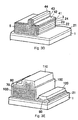
- Fig. 2A-D illustrates a manufacturing method of the end face film to cover a pair of end faces without mask.
- Fig. 3A-E illustrates a manufacturing method of covering the resonator end face other than the light emitting end face with the mask and covering the light emitting end face with the end face film.
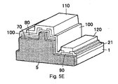
- Fig. 5A-E illustrates the manufacturing method of the laser device which comprises the steps of forming the light emitting end face of the resonator on M-plane, forming the light emitting end face by cleavage after formation of a ridge and electrode, covering the resonator end face other than the light emitting end face with a mask, and covering the light emitting end face with M-place end face film and then forming laser device in the form of tip by cleavage etc.
- the wafer is prepared by growing the buffer layer 11 on the sapphire substrate 1 at a temperature of 700°C or less, depositing successively the n-type nitride semiconductor layer or layers 2, the active layer 3 and the p-type nitride semiconductor layer or layers 4 on the buffer layer 11.
- Fig.2A In this process, if the n-type nitride semiconductor layer or layers 2 are grown on the low temperature buffer layer 11 through ELO layer, the dislocation can be decreased.
- the obtained wafer is subject to an etching process, as a result, the end face of the resonator and the n-type contact layer 21 are uncovered (Fig.2B). Then the end face film 5 is formed, on the wafer whose end faces of the resonator are uncovered, by applying AMMONO method.
- the wafer is placed in an autoclave together with the feedstock as a material for the end face film and with the mineralizer as a reaction accelerator.
- the autoclave is filled with ammonia and a temperature is controlled so as to make the ammonia into the supercritical condition inside the autoclave.
- the wafer successively deposited of the n-type nitride semiconductor layer or layers 2, the active layer 3 and the p-type nitride semiconductor layer or layers 4 on the sapphire substrate 1 is used as the wafer.
- such wafers can be used, for example, a) a wafer where a heterogeneous substrate such as a sapphire substrate is removed, b) a wafer successively deposited of the n-type nitride semiconductor layer or layers 2, the active layer 3 and the p-type nitride semiconductor layer or layers 4 on the sapphire substrate 1, wherein only the light reflecting end face of the resonator is covered with a masking 6 of the materials, i.e.
- the solubility of GaN is high in the supercritical ammonia. Therefore, it is necessary that the surface of the p-type nitride semiconductor layer or layers 4 should be covered with a mask, otherwise the nitride semiconductor device may be dissolved at the corner between the upper surface and the light emitting end face. For this, the p-type contact layer on the top surface of the p-type nitride semiconductor layer or layers 4 is covered with a mask.
- the mask material can be selected from the group consisting of SiO, SiN, AlN, Mo and W. In the supercritical ammonia these materials for mask are more stable than GaN and the dissolution of GaN can be prevented.
- the thickness of the mask may be 1 ⁇ m or more.
- the obtained wafer is provided with the end face film of single crystal Al x Ga 1-x N (0 ⁇ x ⁇ 1) at the uncovered surface of nitride semiconductor layer. (Fig. 2C)
- the laser device can be obtained by removing the end face film from the p-type semiconductor layer or layers 4, forming the protective film on the light emitting end face, forming the reflective film on another end face and cutting out from the groove portion.
- the protective film and the reflective film can be made of the same material, i.e. SiO 2 , TiO 2 or plural films thereof, which have protective effect and reflective effect.
- the wafer is prepared on C-plane of the GaN substrate 1 by successively depositing the n-type nitride semiconductor layer or the layers 2 composed of the n-type contact layer 21, the crack-preventing layer 22, the n-type clad layer 23 and the n-type optical guide layer 24, the active layer 3 and the p-type nitride semiconductor layer or layers 4 composed of the cap layer 41, the p-type optical guide layer 42, the p-type clad layer 43 and the p-type contact layer 44.
- the GaN substrate allows decreasing the dislocation of the epitaxial layer, differently form the first method wherein n-type nitride semiconductor layer or layers 2 are grown on the low temperature buffer layer 11 through ELO layer.
- the wafer is subject to an etching process so that the end faces of the resonator and n-type contact layer 21 are uncovered, and the resonator end face other than the light emitting end face is covered with the mask 7.
- the wafer whose end faces of the resonator are uncovered is covered with the end face film 5 by applying AMMONO method.
- a ridge is formed by a typical device process after the formation of the end face film and removing the mask 7.
- the ridge stripe which performs the optical waveguide is formed in the direction of the resonator.
- the width of the ridge is from 1.0 ⁇ m to 20 ⁇ m and the ridge reaches p-type clad layer or p-type guide layer.
- a buried layer 70 of ZrO 2 film is formed to cover the ridge.
- a p-type ohmic electrode 80 is formed to be in contact with the p-type contact layer 43 which is on the top surface of the ridge. Both of single ridge and plural ridges can be used.
- a multi-stripe-type laser device can be obtained by plural ridges.
- an n-type electrode 90 arranged parallel to the p-type electrode is formed on the surface of the n-type contact layer 21.
- a p-type pad electrode 110 and an n-type pad electrode 120 are formed.
- a SiO 2 / TiO 2 insulating coating is formed to cover the entire device except for the surface of the p-type electrode and the n-type electrode, and due to an alternate arrangement and a patterning of the SiO 2 and TiO 2 layers it serves as the reflecting layer 100 at the moment of laser oscillation.
- each nitride semiconductor laser device is cut out from the wafer by scribing. In this way a finished nitride semiconductor laser device is obtained. (Fig. 3E, Fig. 1)
- the protective film can be formed on the end face film to perform an effective resonance. There is a difference of the reflective index between the protective film and the AlGaN end face film.
- the protective film contains at least one element selected from the group consisting of Nb, Ni, Cr, Ti, Cu, Fe, Zr, Hf, W, Rh, Ru, Mg, Al, Sc, Y, Mo, Ta, Co, Pd, Ag, Au, Pt, Ga and the compound such as oxide, nitride and fluoride thereof.
- A-plane of the GaN substrate 1 is used as a substrate and a light emitting end face is M-plane so that a laser device can be obtained by cleavage.
- a nitride semiconductor laser device is formed on the GaN substrate 1 similarly as the second method.
- the same reference numeral is given to the same element to omit the explanation.
- the n-type contact layer 21 is uncovered by etching (Fig. 5A).
- a ridge is formed (Fig. 5B) and the p-type ohmic electrode 80 is formed to be in contact with the p-type contact layer 43 which is on the top surface of the ridge.
- the n-type electrode 90 is formed on the surface of the n-type contact layer 21, and the p-type pad electrode 110 and the n-type pad electrode 120 are formed.
- the light emitting end face is formed by cleavage so that the wafer becomes in the form of a bar. Moreover, the end face film 5 is formed in a supercritical ammonia.
- the resultant wafer is subject to cleavage so that a laser device can be obtained.
- the negative dissolution curve means that a solubility of the nitride semiconductor is low in the higher temperature zone and a solubility thereof is high in the lower temperature zone.
- the wafer is thus placed in the higher temperature zone, and the feedstock in the lower temperature zone of the reaction system inside the autoclave. Dissolution of the feedstock in the lower temperature zone leads to the oversaturation. In the reaction system, a convection flow is generated, due to which the dissolved feedstock is transported to the higher temperature zone. Due to a lower solubility at the higher temperature zone, the dissolved feedstock becomes recrystallized on the wafer which is a seed. Recrystallization approached in this way results in forming an end face film.
- a characteristic feature of this method is the fact that it allows growth of nitride semiconductor at a temperature of 900°C or less, preferably 600°C or less, and more preferably 500°C or less. Due to this, in the wafer placed in the higher temperature zone a thermal degradation of the active layer containing In does not take place.
- the material of the feedstock depends on the composition of the end face film.
- GaN single crystal, GaN poly crystal, GaN precursor or metallic Ga can generally be used, wherein GaN single crystal or GaN poly crystal can be formed and then recrystallized.
- GaN formed by a vapor phase growth, such as HVPE method or MOCVD method, by AMMONO method, by flux method or by high pressure method can be used.
- the precursor of GaN can contain gallium azide, gallium imide, gallium amide or the mixture thereof.
- AlN similarly as GaN, AlN single crystal, or AlN poly crystal can be used. AlN precursor or metallic Al can also be used. In this case, AlN single crystal or AlN poly crystal can be formed and then recrystallized.
- AlGaN is a mix crystal of AlN and GaN, and the feedstock thereof should be mixed appropriately.
- the usage of metal and single crystal or poly crystal for example, metallic Al and GaN single crystal or poly crystal
- the usage of more than two kinds of mineralizer etc. can lead to a predetermined composition.
- alkali metals such as Li, Na, K, Cs or compounds of alkali metals, such as alkali metal amide, alkali metal imide as a mineralizer.
- a molar ratio of the alkali metal to ammonia ranges from 1:200 to 1:2.
- Li is preferably used.
- Li is a mineralizer whose solubility is low, which leads to restraint of dissolution of the uncovered end face and effective formation of the thin end face film of the thickness from 50 angstrom to 1 ⁇ m.
- the autoclave can typically be made of the alloy containing mainly Ni, Cr and Co, also such elements as Ti, Fe, Al, Si and Mn etc.
- the thickness of the end face film 5 of single crystal Al x Ga 1-x N be 50 angstroms or more. If the thickness thereof is less than 50 angstroms, the effect of smoothing of the etched surface will be lesser. On the other hand the top limit of the thickness may be set to a practical value which can be made.
- the end face film is formed preferably on the lateral surface and the end face of the stripe and also on the surface of the n-type contact layer 21, but it is recommended that overgrowth of the end face film on the surface of the n-type contact layer 21 should be kept at the level of 1 ⁇ m or less not to cover the active layer of the stripe.
- the ratio of Al be lower.
- a small content of Al is desirable. Therefore Al content can be zero, and the end face film 5 should be composed of Al x Ga 1-x N where preferably 0 ⁇ x ⁇ 0.3, and more preferably 0 ⁇ x ⁇ 0.15.
- the end face layer By forming the end face layer on the etched lateral stripe surfaces and the end face, it is possible to make the lateral stripe surfaces and the end face smooth mirrorlike surfaces. In other words, just after being etched the stripe and the end face surfaces are relatively irregular and deposition of the end face film thereon, the end face film fills in irregularities and makes surfaces smooth. Moreover, the end face film can be a single film, but it can be also plural films composed of several layers varied in composition in Al content.
- a sapphire substrate 1 of 2 inch diameter on C-plane as a growth face is placed in a MOCVD reactor. Temperature is set at 510°C. Hydrogen is used as a carrier gas, and ammonia and TMG (thrimethylgallium) are used as gaseous materials. A GaN buffer layer 11 of 200 angstrom thickness is formed on the sapphire substrate, in the conditions of low-temperature growth.
- the following layers are deposited one after the other:
- the formed wafer is subject to annealing in the MOCVD device under the nitrogen atmosphere, at a temperature of 700°C, which additionally reduces resistance of the p-type nitride semiconductor layer.
- the wafer After annealing, the wafer is taken out from the reactor and a protective film (mask) in the form of SiO 2 stripe is deposited on the surface of the top p-type contact layer. Next, by using RIE method, the wafer is etched and stripe is formed, uncovering thereby end faces of the resonator and the surface of the n-type contact layer. The SiO 2 protective film (mask) formed on the surface of the p-type contact layer is removed by using the wet etching method.
- RIE method reactive etching
- the wafer is introduced into the reactor (autoclave), which is filled with a supercritical ammonia.
- the autoclave (36 cm 3 ) is tightly closed at a temperature 500 °C or less inside the autoclave.
- the internal autoclave is divided into two zones: the higher temperature zone and the lower temperature zone. In the higher temperature zone of 550 °C there is a wafer, whereas in the lower temperature zone of 450°C there are feedstock in the form of GaN and Ga metal.
- the sealed autoclave is left for three days.
- the single crystal GaN formed on the surface of the top p-type contact layer is removed by etching.
- the surface of the p-type contact layer is covered with the SiO 2 mask in the form of 1.5 ⁇ m wide strips and etching of the p-type clad layer is continued until ridge is formed on the strip part. Etching is carried out until thickness of the p-type clad layer becomes 0.1 ⁇ m on both sides of ridge.
- a 0.5 ⁇ m thickness ZrO 2 film is formed so that it would cover stripe surfaces over the SiO 2 mask.
- the buried layer 70 in the form of the ZrO 2 film is deposited on the top stripe surface, on lateral face of ridge and on the surface of the p-type clad layer located on both sides of ridge.
- This ZrO 2 film allows stabilizing a lateral mode at the moment of laser oscillation.
- the p-type electrode 80 in the form of Ni/Au is formed on the p-type contact layer so that an ohmic contact would appear, and the n-type electrode 90 in the form of Ti/Al on the n-type contact layer.
- the wafer is subject to thermal processing at a temperature of 600°C.
- a pad electrode in the form of Ni(1000 ⁇ )-Ti(1000 ⁇ )-Au (8000 ⁇ ) are laid on the p-type and n-type electrode.
- a reflecting film 100 in the form of SiO 2 and TiO 2 is formed, each nitride semiconductor laser device is cut out from the wafer by scribing.
- Each nitride semiconductor laser device manufactured in this way is equipped with a heat sink and the laser oscillation is carried out. Due to an increase of a COD level, prolonged continuous oscillation time is expected - with threshold current density: 2.0 kA/cm 2 , power output: 100 mW, preferably 200 mW, and 405 nm oscillation wavelength.
- a single crystal GaN end face film of 1 ⁇ m thickness is grown on the only one light emitting end face on the stripe part, whereas other stages of production of nitride semiconductor laser device are carried out similarly as in Example 1.
- Each laser device manufactured in this way is equipped with a heat sink and the laser oscillation is carried out. Prolonged laser lifetime in continuous oscillation mode is expected - with threshold current density: 2.0 kA/ cm 2 , power output: 100 mW and 405 nm oscillation wavelength - similar as in Example 1.
- Example 1 After the buffer layer is formed on a sapphire substrate, a 100 pm thickness GaN layer is deposited by the HVPE method. Next, as in Example 1, the n-type nitride semiconductor layer, the active layer and the p-type nitride semiconductor layer are formed. Then the sapphire substrate is removed and consequently a homogenous GaN substrate is obtained. In the other stages, as in Example 1, after the formation of an end face of the resonator, single crystal GaN of 100 ⁇ thickness is formed on the end face film in the supercritical ammonia. Nitride semiconductor laser device thus obtained is expected to have the similar effect as in Example 1.
- a 100 pm thickness GaN is deposited through ELO layer by HVPE method.
- the n-type nitride semiconductor layer, the active layer and the p-type nitride semiconductor layer are formed.
- the sapphire substrate is removed and consequently a nitride semiconductor laser device is obtained on a homogenous GaN substrate.
- cleavage is carried out to obtain the growth face for the end face film.
- the single crystal GaN of 1 ⁇ m thickness as an end face film is formed on the light emitting end face in the supercritical ammonia.
- nitride semiconductor laser devices are formed. Nitride semiconductor laser device thus obtained is expected to have the similar effect as in Example 1.
- the sapphire substrate is covered with Ag coating.
- production of the nitride semiconductor laser device is carried out similarly as in Example 1.
- a SiO 2 protective film in the form of lattice pattern is deposited on the surface of the top p-type contact layer.
- etching of RIE method is carried out so as to uncover an end face of a resonator and the surface of the n-type contact layer.
- the wafer is introduced into the reactor (autoclave) inside which is filled with a supercritical ammonia.
- production of the nitride semiconductor laser device is carried out similarly as in Example 1.
- Laser device manufactured in this way is equipped with a heat sink and laser oscillation is carried out. Prolonged laser lifetime in continuous oscillation mode is expected - with threshold current density: 2.0 kA/ cm 2 , power output: 100 mW and 405 nm oscillation wavelength - similarly as in Example 1.
- Single crystal GaN of 100 ⁇ m thickness is used as a substrate.
- the end face is uncovered by cleavage so as to form the end face of the resonator.
- a mask in the form of SiO 2 is formed and end face film is grown.
- Other stages of production of nitride semiconductor laser device are carried out similarly as in Example 1.
- Laser device manufactured in this way is equipped with a heat sink and laser oscillation is carried out. Prolonged laser lifetime in continuous oscillation mode is expected - with threshold current density: 2.0 kA/ cm 2 , power output:: 100 mW and 405 nm oscillation wavelength - similarly as in Example 1.
- a nitride semiconductor laser device comprises an n-type nitride semiconductor layer or layers, a p-type nitride semiconductor layer or layers and a resonator, provided with an active layer comprising nitride semiconductor containing In therebetween, wherein the resonator is provided with a pair of opposed end faces, and at least light emitting end face of the resonator is covered with an end face film of single crystal Al x Ga 1-x N (0 ⁇ x ⁇ 1) formed at a low temperature not causing damage to the active layer. Due to this it is possible to extend the band gap energy in the area of the light emitting end face. This allows disappearance of the light emitting absorption on the end face and increasing the COD level. Owing to this invention it is possible to manufacture a high-output type, i.e. over 100 mW, nitride semiconductor laser device having high reliability and durability.
Landscapes
- Chemical & Material Sciences (AREA)
- Engineering & Computer Science (AREA)
- Physics & Mathematics (AREA)
- Crystallography & Structural Chemistry (AREA)
- Materials Engineering (AREA)
- Organic Chemistry (AREA)
- Metallurgy (AREA)
- Optics & Photonics (AREA)
- Condensed Matter Physics & Semiconductors (AREA)
- General Physics & Mathematics (AREA)
- Electromagnetism (AREA)
- Inorganic Chemistry (AREA)
- Nanotechnology (AREA)
- Biophysics (AREA)
- Life Sciences & Earth Sciences (AREA)
- Semiconductor Lasers (AREA)
- Led Devices (AREA)
- Crystals, And After-Treatments Of Crystals (AREA)
Abstract
The object of this invention is to provide a high-output
type nitride semiconductor laser device comprising a
pair of end faces of a resonator.
The nitride semiconductor laser device comprises an n-type
nitride semiconductor layer or layers, a p-type
nitride semiconductor layer or layers and a resonator,
provided with an active layer comprising nitride
semiconductor containing In therebetween, wherein at least
light emitting end face of the resonator is covered with an
end face film of single crystal AlxGa1-xN (0≤x≤1) formed at
a low temperature not causing damage to the active layer
comprising nitride semiconductor containing In.
Description
This invention relates to a nitride semiconductor
laser device provided with an end face film of single
crystal AlxGa1-xN (0≤x≤1) covering an end face or faces of
the resonator.
In the so-far used semiconductor laser devices made
from GaAs based semiconductors, extension of the lifetime
of a laser device is achieved due to formation of a window
structure where a protective film is formed on end faces of
a resonator in the laser device. Similarly, in a nitride
semiconductor of a nitride semiconductor laser device, end
faces of a resonator are obtained by means of RIE (Reactive
Ion Etching) or cleavage, which makes energy gap of end
faces narrow, resulting in absorption of light and heat
generation on the end faces that leads to impairment of the
lifetime in making high-output type, i.e. over 100mW,
lasers. Therefore, it has been suggested that the window
structure in nitride semiconductor laser device should be
obtained by way of forming a protective film with an
AlGaInN semiconductor film (Japanese Patent Application No.
7-249830) and with a different film such as AlN etc.
(Japanese Patent Application No. 2002-26442).
According to the prior art, it is necessary to apply a
temperature over 1000°C so as to form the above protective
film of single crystal by use of vapor phase growth. Such
high temperature causes damage to the active layer
containing In. When the protective film is formed at a
temperature zone not causing damage to the active layer,
the formed protective film is amorphous. When the amorphous
protective film is used for a window structure in
semiconductor laser device, it brings about diffusion of
emitted light and a laser beam becomes non-homogenous,
because the amorphous protective film is not single crystal.
Moreover, as a result of coloring of amorphous, light
absorption and heating on end faces will occur, which
consequently leads to accelerated degradation of end faces.
The object of this invention is to provide a nitride
semiconductor laser device provided with end faces which is
covered by a film of single crystal AlxGa1-xN (0≤x≤1) formed
at a low temperature zone not causing damage to the active
layer.
According to the present invention, there is provided
a nitride semiconductor laser device comprises an n-type
nitride semiconductor layer or layers, a p-type nitride
semiconductor layer or layers and a resonator, provided
with an active layer comprising nitride semiconductor
containing In therebetween, wherein the resonator is
provided with a pair of opposed end faces, and at least one
of the light emitting end faces of the resonator is covered
with an end face film of single crystal AlxGa1-xN (0≤x≤1)
having larger band gap energy than that of the active layer
and formed at a low temperature not causing damage to the
active layer.
A desired temperature not causing damage to the active
layer comprising nitride semiconductor containing In should
be lower than a temperature at which the active layer
comprising nitride semiconductor containing In is formed.
The active layer comprising nitride semiconductor
containing In is grown usually at 900°C and that
temperature or less does not cause damage to the active
layer due to degradation etc. Therefore, the end face film
should be grown at 900°C or less, preferably 600°C or less,
more preferably 500°C or less.
In nitride semiconductor laser devices according to
this invention, a resonator provided with an active layer
comprising nitride semiconductor containing In means an
optical waveguide region which is commonly comprised of an
active layer and an optical guide layer. According to this
invention, at least one of the end faces of the resonator
region should be covered with an end face film. The
active layer should include a single quantum well or a
multi quantum well structure, provided with at least one of
the well layers: InGaN or InAlGaN.
The end face film according to this invention is
comprised of single crystal AlxGa1-xN (0≤x≤1). The mixture
ratio of crystal should be determined in relation to the
function of the end face film. Within the light emitting
end face of the active layer the band gap energy becomes
narrower due to etching or cleavage for forming the light
emitting end face. The mixture ratio of crystal should be
thus determined in such a way that the end face film could
contribute to widening of the energy gap of the end face
and disappearance of the light emitting absorption.
Considering the crystalline property of the end face film,
the Al ratio in the crystal is 0.3 or less, preferably 0.15
or less. In nitride semiconductor laser device according
to this invention, the end face film has preferably a
thickness of 50 angstrom or more. Moreover, to obtain the
uniformity of the end face film, the thickness thereof
should be 1 µm or less, more preferably 2000 angstrom or
less.
According to the present invention, AMMONO method may
be applied to form the single crystal AlxGa1-xN (0≤x≤1) at a
low temperature. Using of AMMONO method, under a
supercritical condition of ammonia, the single crystal
AlxGa1-xN (0≤x≤1) layer can be grown on a predetermined seed
face, i.e. an end face of the resonator in the laser device
according to this invention, and the end face film of
single crystal can be formed at a temperature 900 °C or
less, preferably 600 °C or less, more preferably 500 °C or
less. In the AMMONO method, the end face film can be
usually influenced by the autoclave composition and can
contain at least one element selected from the group
consisting of Ni, Cr, Co, Ti, Fe, Al, Si and Mn. The
AMMONO method is characterized in that the end face film
includes at least one element, used as a mineralizer, from
Group No. 1 (IUPAC. 1989) element, Li, K, Na or Cs.
According to the present invention, light from the nitride
semiconductor laser device can not be absorbed on the end
face film, which leads no heat absorption on the light
emitting end face and COD generation can be reduced in the
nitride semiconductor laser device at the power output 100
mW or more.
The nitride semiconductor laser device can be formed
on the substrate selected from the group consisting of GaN
substrate, sapphire substrate, spinel substrate, ZnO
substrate, SiC substrate, ELO growth substrate formed on
the heterogeneous substrate, for example Sapphire substrate
etc, in the lateral direction growth of GaN and a substrate
provided with a nitride semiconductor having an irregular
surface. ELO (Epitaxial-Lateral-Overgrowth) substrate
utilizes the lateral direction growth of GaN and allows
reducing the dislocation density. According to the
present invention, GaN substrate is preferably applied to
become grown AlxGa1-xN (0≤x≤1) as an end face film in the
supercritical ammonia. In case that the nitride
semiconductor laser device provided with a heterogeneous
substrate whose composition is different from that of the
end face film, the GaN substrate prevent the heterogeneous
substrate to be dissolved in the supercritical ammonia and
recrystallized into the end face film semiconductor and to
become the impurity during the formation of the end face
film. The GaN substrate means GaN substrate grown by means
of supercritical ammonia method and so on. Nitride
semiconductor laser devices grown on the different
substrate from that of nitride semiconductor has difficulty
in cleavage during the device processes, because the
heterogeneous substrates on which GaN is grown do not have
a cleavage property. However, GaN substrate has a
cleavage property and the end face can be obtained by
cleavage which performs excellently at forming the mirror
faces. Moreover, GaN substrate for homo-epitaxial growth
can prevent a curving after the laser device is prepared.
It leads to avoid occurrence of cracking. Moreover, laser
devices are usually grown on C-plane of the GaN substrate,
because the GaN substrate is obtained by means of VPE
(Vapor Phase Epitaxy). Using AMMONO method, after GaN bulk
single crystal having thickness of 2.5 cm or more is grown
in the direction of C-axis in the supercritical ammonia, a
resultant GaN substrate is cut so as to obtain a GaN
substrate having 1 inch or more diameters and having an A-plane
or M-plane as a main plane. A-plane and M-plane
having non-polar do not give a polarization effect to the
active layer. Moreover, the dislocation density thereof is
104/cm2 or less. Otherwise, GaN substrate having (000-1)
main plane can be changed into the substrate having (0001)
main plane (C-plane) by means of polarity conversion.
In case that the nitride semiconductor laser device is
grown on C-plane of GaN substrate, the end film is formed
on M-plane or A-plane so that the end film having non-polar
can be obtained. When the nitride semiconductor laser
device is grown on A-plane of GaN substrate formed in the
supercritical ammonia, the active layer of the laser device
is not influenced by the polarization effect. The light
emitting face of the resonator is M-plane, on which the end
face film is formed and cleavage is easily performed. In
case that the nitride semiconductor laser device is grown
on M-plane of GaN substrate formed in the supercritical
ammonia, the active layer is not influenced by the
polarization effect and A-plane end face film having non-polar
can be obtained on the light emitting face of the
resonator.
According to a second aspect of the present invention,
there is provided a method for manufacturing a nitride
semiconductor laser device which comprises an n-type
nitride semiconductor layer or layers, a p-type nitride
semiconductor layer or layers and a resonator, provided
with an active layer comprising nitride semiconductor
containing In therebetween, which comprises: (1) etching or
cleaving the laser device so that a pair of the opposed end
faces in the resonator are formed; and (2) covering at
least light emitting end face of the opposed end faces in
the resonator with a film of single crystal AlxGa1-xN
(0≤x≤1) formed at a low temperature not causing damage to
the active layer, wherein the end face film of single
crystal AlxGa1-xN (0≤x≤1 ) can be obtained in the
supercritical ammonia at a low temperature not causing
damage to the active layer, and wherein the end face film
is formed after at least an upper surface of the resonator
p-type contact layer is covered with a mask having lower or
same solubility in the supercritical ammonia than that of
the end face film. The formation of the mask can prevent
the dissolution of the resonator of the laser device at the
corner between the upper surface of the p-type contact
layer and the end face when the end face film of the
nitride semiconductor laser device is formed in the
supercritical ammonia having high solubility. The mask may
be selected from the group consisting of SiO, SiN, AlN, Mo
and W. In the supercritical ammonia these materials for
mask are more stable than GaN and the dissolution of the
contact surface covered with the mask material can be
prevented. In a later process, i.e. a formation process of
a ridge or ridges, the mask can be easily removed.
In the method of manufacturing the nitride
semiconductor laser device, the end face film is grown in
the supercritical ammonia at a temperature from 100°C to
900°C. The active layer having the quantum well structure
containing InGaN of the nitride semiconductor laser device
could be degraded, in case that the layers in the nitride
semiconductor laser device are grown on the active layer at
a temperature over 900°C. According to this invention, the
end face film can be grown at a temperature of 900°C or
less, preferably 600°C or less.
Further herein a detailed description of the
embodiments of the present invention is provided.
The schematic sectional view of the semiconductor
laser according to the present invention is shown in Fig.1.
On the sapphire substrate 1 the n-type nitride
semiconductor layer or layers 2 and the p-type nitride
semiconductor layer or layers 4 are deposited. Between them
there is the active layer 3 of a single quantum well or a
multi quantum well structure in the form of a nitride
semiconductor containing In. This results in the laser
device having the good light emitting efficiency at the
wavelength region between near-ultraviolet and green
visible light (from 370 nm to 550 nm). The n-type nitride
semiconductor layer or layers 2 are composed of an n-type
contact layer 21, a crack-preventing layer 22, an n-type
clad layer 23 and an n-type optical guide layer 24. The
crack-preventing layer 22 can be omitted when GaN substrate
is used, because the wafer curving can be prevented. The
p-type nitride semiconductor layer or layers 4 are composed
of a cap layer 41, a p-type optical guide layer 42, a p-type
clad layer 43 and a p-type contact layer 44. The n-type
contact layer 21 can be formed on the sapphire
substrate 1 through ELO layer for decreasing dislocation or
AlGaN layer for decreasing the pits. In the above
embodiment, the resonator of the semiconductor laser device
is composed of the active layer 3, the p-type optical guide
layer 24, n-type optical guide layer 42 and the cap layer
41. The light emitting end face of the resonator is covered
with the end face film 5 of single crystal AlxGa1-xN
(0≤x≤1) . If the light emitting face of the resonator is
covered with the end face film (shown in Fig.2), it is
possible to reduce damage caused by reflected light.
Further herein the three typical manufacturing methods
of the nitride semiconductor laser device of the present
embodiment are provided.
Fig. 2A-D illustrates a manufacturing method of the
end face film to cover a pair of end faces without mask.
Fig. 3A-E illustrates a manufacturing method of
covering the resonator end face other than the light
emitting end face with the mask and covering the light
emitting end face with the end face film.
Fig. 5A-E illustrates the manufacturing method of the
laser device which comprises the steps of forming the light
emitting end face of the resonator on M-plane, forming the
light emitting end face by cleavage after formation of a
ridge and electrode, covering the resonator end face other
than the light emitting end face with a mask, and covering
the light emitting end face with M-place end face film and
then forming laser device in the form of tip by cleavage
etc.
The first method shown in Fig. 2, the wafer is
prepared by growing the buffer layer 11 on the sapphire
substrate 1 at a temperature of 700°C or less, depositing
successively the n-type nitride semiconductor layer or
layers 2, the active layer 3 and the p-type nitride
semiconductor layer or layers 4 on the buffer layer 11.
(Fig.2A) In this process, if the n-type nitride
semiconductor layer or layers 2 are grown on the low
temperature buffer layer 11 through ELO layer, the
dislocation can be decreased.
Next, the obtained wafer is subject to an etching
process, as a result, the end face of the resonator and the
n-type contact layer 21 are uncovered (Fig.2B). Then the
end face film 5 is formed, on the wafer whose end faces of
the resonator are uncovered, by applying AMMONO method.
The wafer is placed in an autoclave together with the
feedstock as a material for the end face film and with the
mineralizer as a reaction accelerator. The autoclave is
filled with ammonia and a temperature is controlled so as
to make the ammonia into the supercritical condition inside
the autoclave.
The wafer successively deposited of the n-type nitride
semiconductor layer or layers 2, the active layer 3 and the
p-type nitride semiconductor layer or layers 4 on the
sapphire substrate 1 is used as the wafer. Instead of that,
such wafers can be used, for example, a) a wafer where a
heterogeneous substrate such as a sapphire substrate is
removed, b) a wafer successively deposited of the n-type
nitride semiconductor layer or layers 2, the active layer 3
and the p-type nitride semiconductor layer or layers 4 on
the sapphire substrate 1, wherein only the light reflecting
end face of the resonator is covered with a masking 6 of
the materials, i.e. Ag etc, which are not dissolved in a
supercritical ammonia or are not mixed into the end face
film in case of dissolution, c) a wafer where any other
faces than light emitting end face are wholly covered with
the masking 6 of Ag etc, d) a wafer wherein only the
substrate is covered with the masking (Fig. 4).
The solubility of GaN is high in the supercritical
ammonia. Therefore, it is necessary that the surface of the
p-type nitride semiconductor layer or layers 4 should be
covered with a mask, otherwise the nitride semiconductor
device may be dissolved at the corner between the upper
surface and the light emitting end face. For this, the p-type
contact layer on the top surface of the p-type nitride
semiconductor layer or layers 4 is covered with a mask.
The mask material can be selected from the group consisting
of SiO, SiN, AlN, Mo and W. In the supercritical ammonia
these materials for mask are more stable than GaN and the
dissolution of GaN can be prevented. It means that covering
the p-type contact layer with a mask leads to restraint of
the dissolution at the corner between the p-type contact
layer and the light emitting end face. In the process
after the formation of the end face film, the mask being
easily removed is preferred. The thickness of the mask may
be 1 µm or more.
After the wafer is reacted in the autoclave, the
obtained wafer is provided with the end face film of single
crystal AlxGa1-xN (0≤x≤1) at the uncovered surface of
nitride semiconductor layer. (Fig. 2C)
In the next process, the laser device can be obtained
by removing the end face film from the p-type semiconductor
layer or layers 4, forming the protective film on the light
emitting end face, forming the reflective film on another
end face and cutting out from the groove portion. The
protective film and the reflective film can be made of the
same material, i.e. SiO2, TiO2 or plural films thereof,
which have protective effect and reflective effect.
In the second method shown in Fig. 3, the wafer is
prepared on C-plane of the GaN substrate 1 by successively
depositing the n-type nitride semiconductor layer or the
layers 2 composed of the n-type contact layer 21, the
crack-preventing layer 22, the n-type clad layer 23 and the
n-type optical guide layer 24, the active layer 3 and the
p-type nitride semiconductor layer or layers 4 composed of
the cap layer 41, the p-type optical guide layer 42, the p-type
clad layer 43 and the p-type contact layer 44.
(Fig.3A) In this process, the GaN substrate allows
decreasing the dislocation of the epitaxial layer,
differently form the first method wherein n-type nitride
semiconductor layer or layers 2 are grown on the low
temperature buffer layer 11 through ELO layer.
Next, the wafer is subject to an etching process so
that the end faces of the resonator and n-type contact
layer 21 are uncovered, and the resonator end face other
than the light emitting end face is covered with the mask 7.
(Fig.3B) Then the wafer whose end faces of the resonator
are uncovered is covered with the end face film 5 by
applying AMMONO method. (Fig 3C)
Next, a ridge is formed by a typical device process
after the formation of the end face film and removing the
mask 7. (Fig. 3D) The ridge stripe which performs the
optical waveguide is formed in the direction of the
resonator. The width of the ridge is from 1.0 µm to 20 µm
and the ridge reaches p-type clad layer or p-type guide
layer. Next, a buried layer 70 of ZrO2 film is formed to
cover the ridge. A p-type ohmic electrode 80 is formed to
be in contact with the p-type contact layer 43 which is on
the top surface of the ridge. Both of single ridge and
plural ridges can be used. A multi-stripe-type laser device
can be obtained by plural ridges.
Next, an n-type electrode 90 arranged parallel to the
p-type electrode is formed on the surface of the n-type
contact layer 21. In further sequence, a p-type pad
electrode 110 and an n-type pad electrode 120 are formed.
Moreover, a SiO2 / TiO2 insulating coating is formed to
cover the entire device except for the surface of the p-type
electrode and the n-type electrode, and due to an
alternate arrangement and a patterning of the SiO2 and TiO2
layers it serves as the reflecting layer 100 at the moment
of laser oscillation. Finally, each nitride semiconductor
laser device is cut out from the wafer by scribing. In this
way a finished nitride semiconductor laser device is
obtained. (Fig. 3E, Fig. 1)
Moreover, the protective film can be formed on the end
face film to perform an effective resonance. There is a
difference of the reflective index between the protective
film and the AlGaN end face film. Concretely, the
protective film contains at least one element selected from
the group consisting of Nb, Ni, Cr, Ti, Cu, Fe, Zr, Hf, W,
Rh, Ru, Mg, Al, Sc, Y, Mo, Ta, Co, Pd, Ag, Au, Pt, Ga and
the compound such as oxide, nitride and fluoride thereof.
In the third method shown in Fig. 5A-E, A-plane of the
GaN substrate 1 is used as a substrate and a light emitting
end face is M-plane so that a laser device can be obtained
by cleavage. A nitride semiconductor laser device is
formed on the GaN substrate 1 similarly as the second
method. The same reference numeral is given to the same
element to omit the explanation. Next, the n-type contact
layer 21 is uncovered by etching (Fig. 5A). Then a ridge
is formed (Fig. 5B) and the p-type ohmic electrode 80 is
formed to be in contact with the p-type contact layer 43
which is on the top surface of the ridge. Next, the n-type
electrode 90 is formed on the surface of the n-type contact
layer 21, and the p-type pad electrode 110 and the n-type
pad electrode 120 are formed. (Fig. 5C) Next, the light
emitting end face is formed by cleavage so that the wafer
becomes in the form of a bar. Moreover, the end face film
5 is formed in a supercritical ammonia. (Fig. 5D) The
resultant wafer is subject to cleavage so that a laser
device can be obtained. (Fig. 5E)
In AMMONO method using supercritical ammonia, a
nitride semiconductor is grown in a supercritical ammonia
wherein a nitride gallium compound has the negative
dissolution curve. Detailed explanation of the method is
disclosed in Polish Patent Application Nos. P-347918, P-350375
and PCT Application No. PCT/IB02/04185. Those
skilled in the art can easily carry out the present
invention with reference to the abstract and examples
explained below.
AMMONO method is summarized as follows. In the
reaction system, the negative dissolution curve means that
a solubility of the nitride semiconductor is low in the
higher temperature zone and a solubility thereof is high in
the lower temperature zone. When the temperature
difference is controlled properly in the higher temperature
zone and the lower temperature zone inside the autoclave,
nitrides are dissolved in the lower temperature zone and
nitrides are recrystallized in the higher temperature zone.
Due to a generated convection flow from the lower
temperature zone to the higher temperature zone, a
predetermined concentration of nitrides can be kept in the
higher temperature zone and the nitrides can be selectively
grown on a seed.
The wafer is thus placed in the higher temperature
zone, and the feedstock in the lower temperature zone of
the reaction system inside the autoclave. Dissolution of
the feedstock in the lower temperature zone leads to the
oversaturation. In the reaction system, a convection flow
is generated, due to which the dissolved feedstock is
transported to the higher temperature zone. Due to a lower
solubility at the higher temperature zone, the dissolved
feedstock becomes recrystallized on the wafer which is a
seed. Recrystallization approached in this way results in
forming an end face film. Moreover, a characteristic
feature of this method, as compared to the methods by which
nitride semiconductor is formed from a vapor phase growth
at a temperature over 900°C, is the fact that it allows
growth of nitride semiconductor at a temperature of 900°C
or less, preferably 600°C or less, and more preferably
500°C or less. Due to this, in the wafer placed in the
higher temperature zone a thermal degradation of the active
layer containing In does not take place.
The material of the feedstock depends on the
composition of the end face film. In case that the end
face film of GaN is formed, GaN single crystal, GaN poly
crystal, GaN precursor or metallic Ga can generally be used,
wherein GaN single crystal or GaN poly crystal can be
formed and then recrystallized. GaN formed by a vapor
phase growth, such as HVPE method or MOCVD method, by
AMMONO method, by flux method or by high pressure method
can be used. The precursor of GaN can contain gallium
azide, gallium imide, gallium amide or the mixture thereof.
Regarding AlN, similarly as GaN, AlN single crystal,
or AlN poly crystal can be used. AlN precursor or metallic
Al can also be used. In this case, AlN single crystal or
AlN poly crystal can be formed and then recrystallized.
AlGaN is a mix crystal of AlN and GaN, and the
feedstock thereof should be mixed appropriately. Moreover,
the usage of metal and single crystal or poly crystal (for
example, metallic Al and GaN single crystal or poly
crystal) or the usage of more than two kinds of mineralizer
etc. can lead to a predetermined composition.
It is possible to use alkali metals, such as Li, Na,
K, Cs or compounds of alkali metals, such as alkali metal
amide, alkali metal imide as a mineralizer. A molar ratio
of the alkali metal to ammonia ranges from 1:200 to 1:2. Li
is preferably used. Li is a mineralizer whose solubility
is low, which leads to restraint of dissolution of the
uncovered end face and effective formation of the thin end
face film of the thickness from 50 angstrom to 1 µm.
The autoclave can typically be made of the alloy
containing mainly Ni, Cr and Co, also such elements as Ti,
Fe, Al, Si and Mn etc.
According to the present invention it is recommended
that the thickness of the end face film 5 of single crystal
AlxGa1-xN be 50 angstroms or more. If the thickness thereof
is less than 50 angstroms, the effect of smoothing of the
etched surface will be lesser. On the other hand the top
limit of the thickness may be set to a practical value
which can be made. Moreover, according to the present
invention, the end face film is formed preferably on the
lateral surface and the end face of the stripe and also on
the surface of the n-type contact layer 21, but it is
recommended that overgrowth of the end face film on the
surface of the n-type contact layer 21 should be kept at
the level of 1 µm or less not to cover the active layer of
the stripe.
To improve the smoothing effect of the end face film
5, it is recommended that the ratio of Al be lower.
Nevertheless, according to the present invention, to
improve the operation of the window structure, a small
content of Al is desirable. Therefore Al content can be
zero, and the end face film 5 should be composed of
AlxGa1-xN where preferably 0≤x≤0.3, and more preferably
0≤x≤0.15.
By forming the end face layer on the etched lateral
stripe surfaces and the end face, it is possible to make
the lateral stripe surfaces and the end face smooth mirrorlike
surfaces. In other words, just after being etched the
stripe and the end face surfaces are relatively irregular
and deposition of the end face film thereon, the end face
film fills in irregularities and makes surfaces smooth.
Moreover, the end face film can be a single film, but it
can be also plural films composed of several layers varied
in composition in Al content.
The following examples are intended to illustrate the
present invention and should not be construed as being
limiting.
First, a sapphire substrate 1 of 2 inch diameter on C-plane
as a growth face is placed in a MOCVD reactor.
Temperature is set at 510°C. Hydrogen is used as a carrier
gas, and ammonia and TMG (thrimethylgallium) are used as
gaseous materials. A GaN buffer layer 11 of 200 angstrom
thickness is formed on the sapphire substrate, in the
conditions of low-temperature growth.
On the buffer layer, the following layers are
deposited one after the other:
After the above layers are deposited, the formed wafer
is subject to annealing in the MOCVD device under the
nitrogen atmosphere, at a temperature of 700°C, which
additionally reduces resistance of the p-type nitride
semiconductor layer.
After annealing, the wafer is taken out from the
reactor and a protective film (mask) in the form of SiO2
stripe is deposited on the surface of the top p-type
contact layer. Next, by using RIE method, the wafer is
etched and stripe is formed, uncovering thereby end faces
of the resonator and the surface of the n-type contact
layer. The SiO2 protective film (mask) formed on the
surface of the p-type contact layer is removed by using the
wet etching method.
Next, the wafer is introduced into the reactor
(autoclave), which is filled with a supercritical ammonia.
Having been filled with the feedstock in the form of GaN of
0.5 g, ammonia of 14.7 g and mineralizer in the form of Li
of 0.036 g, the autoclave (36 cm3) is tightly closed at a
temperature 500 °C or less inside the autoclave. The
internal autoclave is divided into two zones: the higher
temperature zone and the lower temperature zone. In the
higher temperature zone of 550 °C there is a wafer, whereas
in the lower temperature zone of 450°C there are feedstock
in the form of GaN and Ga metal. The sealed autoclave is
left for three days.
Under the low temperature condition, in the
supercritical ammonia 100 angstrom thickness single crystal
GaN end face film is grown on the stripe end face, stripe
lateral face and uncovered surfaces of the n-type contact
layer and p-type contact layer.
After a single crystal GaN end face film is formed,
the single crystal GaN formed on the surface of the top p-type
contact layer is removed by etching. Next, the surface
of the p-type contact layer is covered with the SiO2 mask
in the form of 1.5 µm wide strips and etching of the p-type
clad layer is continued until ridge is formed on the strip
part. Etching is carried out until thickness of the p-type
clad layer becomes 0.1 µm on both sides of ridge.
In this way a ridge part of 1.5 pm width is formed.
Next, by use of the ion sputtering method, a 0.5 µm
thickness ZrO2 film is formed so that it would cover stripe
surfaces over the SiO2 mask.
After thermal processing, the buried layer 70 in the
form of the ZrO2 film is deposited on the top stripe
surface, on lateral face of ridge and on the surface of the
p-type clad layer located on both sides of ridge. This ZrO2
film allows stabilizing a lateral mode at the moment of
laser oscillation.
Next the p-type electrode 80 in the form of Ni/Au is
formed on the p-type contact layer so that an ohmic contact
would appear, and the n-type electrode 90 in the form of
Ti/Al on the n-type contact layer. Then, the wafer is
subject to thermal processing at a temperature of 600°C.
Next, a pad electrode in the form of Ni(1000Å)-Ti(1000Å)-Au
(8000Å) are laid on the p-type and n-type electrode.
After a reflecting film 100 in the form of SiO2 and TiO2 is
formed, each nitride semiconductor laser device is cut out
from the wafer by scribing.
Each nitride semiconductor laser device manufactured
in this way is equipped with a heat sink and the laser
oscillation is carried out. Due to an increase of a COD
level, prolonged continuous oscillation time is expected -
with threshold current density: 2.0 kA/cm2, power output:
100 mW, preferably 200 mW, and 405 nm oscillation
wavelength.
A single crystal GaN end face film of 1 µm thickness
is grown on the only one light emitting end face on the
stripe part, whereas other stages of production of nitride
semiconductor laser device are carried out similarly as in
Example 1.
Each laser device manufactured in this way is equipped
with a heat sink and the laser oscillation is carried out.
Prolonged laser lifetime in continuous oscillation mode is
expected - with threshold current density: 2.0 kA/ cm2,
power output: 100 mW and 405 nm oscillation wavelength -
similar as in Example 1.
After the buffer layer is formed on a sapphire
substrate, a 100 pm thickness GaN layer is deposited by the
HVPE method. Next, as in Example 1, the n-type nitride
semiconductor layer, the active layer and the p-type
nitride semiconductor layer are formed. Then the sapphire
substrate is removed and consequently a homogenous GaN
substrate is obtained. In the other stages, as in Example
1, after the formation of an end face of the resonator,
single crystal GaN of 100 Å thickness is formed on the end
face film in the supercritical ammonia. Nitride
semiconductor laser device thus obtained is expected to
have the similar effect as in Example 1.
After the buffer layer is formed on a sapphire
substrate, a 100 pm thickness GaN is deposited through ELO
layer by HVPE method. Next, as in Example 1, the n-type
nitride semiconductor layer, the active layer and the p-type
nitride semiconductor layer are formed. Then the
sapphire substrate is removed and consequently a nitride
semiconductor laser device is obtained on a homogenous GaN
substrate. By using the cleavage property of the
homogenous GaN substrate, cleavage is carried out to obtain
the growth face for the end face film. Next, the single
crystal GaN of 1 µm thickness as an end face film is formed
on the light emitting end face in the supercritical ammonia.
In the other stages, as in Example 1, after the formation
of an end face of a resonator, nitride semiconductor laser
devices are formed. Nitride semiconductor laser device
thus obtained is expected to have the similar effect as in
Example 1.
The sapphire substrate is covered with Ag coating. In
other respects, production of the nitride semiconductor
laser device is carried out similarly as in Example 1.
A SiO2 protective film in the form of lattice pattern
is deposited on the surface of the top p-type contact
layer. Next, etching of RIE method is carried out so as to
uncover an end face of a resonator and the surface of the
n-type contact layer. Under the condition of the SiO2
mask of 0.5 µm thickness formed on the surface of the p-type
contact layer, the wafer is introduced into the
reactor (autoclave) inside which is filled with a
supercritical ammonia. In other respects, production of
the nitride semiconductor laser device is carried out
similarly as in Example 1.
Laser device manufactured in this way is equipped with
a heat sink and laser oscillation is carried out. Prolonged
laser lifetime in continuous oscillation mode is expected -
with threshold current density: 2.0 kA/ cm2, power output:
100 mW and 405 nm oscillation wavelength - similarly as in
Example 1.
Single crystal GaN of 100 µm thickness is used as a
substrate. The end face is uncovered by cleavage so as to
form the end face of the resonator. Next, a mask in the
form of SiO2 is formed and end face film is grown. Other
stages of production of nitride semiconductor laser device
are carried out similarly as in Example 1.
Laser device manufactured in this way is equipped with
a heat sink and laser oscillation is carried out. Prolonged
laser lifetime in continuous oscillation mode is expected -
with threshold current density: 2.0 kA/ cm2, power output::
100 mW and 405 nm oscillation wavelength - similarly as in
Example 1.
A nitride semiconductor laser device comprises an n-type
nitride semiconductor layer or layers, a p-type
nitride semiconductor layer or layers and a resonator,
provided with an active layer comprising nitride
semiconductor containing In therebetween, wherein the
resonator is provided with a pair of opposed end faces, and
at least light emitting end face of the resonator is
covered with an end face film of single crystal AlxGa1-xN
(0≤x≤1) formed at a low temperature not causing damage to
the active layer. Due to this it is possible to extend the
band gap energy in the area of the light emitting end face.
This allows disappearance of the light emitting absorption
on the end face and increasing the COD level. Owing to this
invention it is possible to manufacture a high-output type,
i.e. over 100 mW, nitride semiconductor laser device having
high reliability and durability.
Claims (16)
- A nitride semiconductor laser device which comprises an n-type nitride semiconductor layer or layers, a p-type nitride semiconductor layer or layers and a resonator, provided with an active layer comprising nitride semiconductor containing In therebetween,
wherein said resonator is provided with a pair of opposed end faces, and at least light emitting end face of said resonator is covered with an end face film of single crystal AlxGa1-xN (0≤x≤1) having larger band gap energy than that of the active layer and formed at a low temperature not causing damage to said active layer. - The nitride semiconductor laser device according to claim 1, characterized in that a thickness of said end face film is from 50 angstrom to 1 µm.
- The nitride semiconductor laser device according to claim 1, wherein said end face of the resonator is covered with the end face film of single crystal AlxGa1-xN (0 ≦ x ≦ 1) in a supercritical ammonia.
- The nitride semiconductor laser device according to claim 3, wherein a p-type contact layer of said resonator is subject to at least masking and then said end face of said resonator is covered with the end face film of single crystal AlxGa1-xN (0≦x≦1) in a supercritical ammonia.
- The nitride semiconductor laser device according to claim 3, characterized in that said end face film includes at least one of the elements of Group I (IUPAC, 1989).
- The nitride semiconductor laser device according to claim 1, wherein said active layer includes a quantum well structure comprising at least one InGaN well layer or InAlGaN well layer.
- The nitride semiconductor laser device according to any one of claims 1 to 6, wherein said nitride semiconductor laser device is formed on the substrate selected from the group consisting of GaN substrate, sapphire substrate, spinel substrate, ZnO substrate, SiC substrate, ELO growth substrate and a substrate provided with a nitride semiconductor having an irregular surface.
- The nitride semiconductor laser device according to any one of claims 1 to 7, wherein said nitride semiconductor laser device is formed on C-plane, A-plane or M-plane of GaN substrate.
- The nitride semiconductor laser device according to claim 1, wherein said nitride semiconductor laser device is formed on C-plane of GaN substrate and said end face film is grown on M-plane or A-plane.
- The nitride semiconductor laser device according to claim 1, wherein said nitride semiconductor laser device is formed on A-plane of GaN substrate, and the light emitting face of said resonator is M-plane, on which said end face film is formed.
- The nitride semiconductor laser device according to claim 1, wherein said nitride semiconductor laser device is formed on M-plane of GaN substrate grown in the supercritical ammonia, and the light emitting face of said resonator is A-plane, on which said end face film is formed.
- A method of manufacturing a nitride semiconductor laser device which comprises an n-type nitride semiconductor layer or layers, a p-type nitride semiconductor layer or layers and a resonator, provided with an active layer comprising nitride semiconductor containing In therebetween, which comprises:(1) etching or cleaving said laser device so that a pair of the opposed end faces of the resonator are formed;(2) covering at least light emitting end face of said opposed end faces in the resonator with a film of single crystal AlxGa1-xN (0≤x≤1) formed at a low temperature not causing damage to said active layer.
- The method for manufacturing a nitride semiconductor laser device according to claim 12, characterized in that during said second process said end face film is formed in a supercritical ammonia.
- The method for manufacturing a nitride semiconductor laser device according to claim 13, characterized in that during the second process said end face film is formed after at least upper surface of the resonator p-type contact layer is covered with a mask having lower or same solubility in the supercritical ammonia than that of end face film composition.
- The method for manufacturing a nitride semiconductor laser device according to claim 14, characterized in that said mask is selected from the group consisting of SiO, SiN., AlN, Mo and W.
- The method for manufacturing a nitride semiconductor laser device according to claim 12, characterized in that said end face film is grown in the form of single crystal in the supercritical ammonia at a temperature of 900°C or less, preferably 600°C or less.
Applications Claiming Priority (5)
| Application Number | Priority Date | Filing Date | Title |
|---|---|---|---|
| PL35037501A PL350375A1 (en) | 2001-10-26 | 2001-10-26 | Epitaxial layer substrate |
| PL35037501 | 2001-10-26 | ||
| PL02354739A PL354739A1 (en) | 2002-06-26 | 2002-06-26 | Nitride semiconductor laser |
| PL35473902 | 2002-06-26 | ||
| PCT/JP2002/011136 WO2003036771A1 (en) | 2001-10-26 | 2002-10-28 | Nitride semiconductor laser element, and production method therefor |
Publications (2)
| Publication Number | Publication Date |
|---|---|
| EP1453158A1 true EP1453158A1 (en) | 2004-09-01 |
| EP1453158A4 EP1453158A4 (en) | 2007-09-19 |
Family
ID=26653408
Family Applications (2)
| Application Number | Title | Priority Date | Filing Date |
|---|---|---|---|
| EP02775396A Withdrawn EP1453158A4 (en) | 2001-10-26 | 2002-10-28 | Nitride semiconductor laser element, and production method therefor |
| EP02803072.4A Expired - Lifetime EP1453159B8 (en) | 2001-10-26 | 2002-10-28 | Light emitting device structure using nitride bulk single crystal layer |
Family Applications After (1)
| Application Number | Title | Priority Date | Filing Date |
|---|---|---|---|
| EP02803072.4A Expired - Lifetime EP1453159B8 (en) | 2001-10-26 | 2002-10-28 | Light emitting device structure using nitride bulk single crystal layer |
Country Status (8)
| Country | Link |
|---|---|
| US (3) | US7057211B2 (en) |
| EP (2) | EP1453158A4 (en) |
| JP (2) | JP4383172B2 (en) |
| KR (2) | KR100679377B1 (en) |
| CN (2) | CN1300901C (en) |
| PL (2) | PL374180A1 (en) |
| TW (1) | TWI263387B (en) |
| WO (2) | WO2003043150A1 (en) |
Cited By (1)
| Publication number | Priority date | Publication date | Assignee | Title |
|---|---|---|---|---|
| US8269251B2 (en) | 2007-05-17 | 2012-09-18 | Mitsubishi Chemical Corporation | Method for producing group III nitride semiconductor crystal, group III nitride semiconductor substrate, and semiconductor light-emitting device |
Families Citing this family (153)
| Publication number | Priority date | Publication date | Assignee | Title |
|---|---|---|---|---|
| US6596079B1 (en) | 2000-03-13 | 2003-07-22 | Advanced Technology Materials, Inc. | III-V nitride substrate boule and method of making and using the same |
| JP4116535B2 (en) | 2001-06-06 | 2008-07-09 | アンモノ・スプウカ・ジ・オグラニチョノン・オドポヴィエドニアウノシツィオン | Method and apparatus for producing gallium-containing nitride single crystal |
| US7057211B2 (en) * | 2001-10-26 | 2006-06-06 | Ammono Sp. Zo.O | Nitride semiconductor laser device and manufacturing method thereof |
| AU2002347692C1 (en) * | 2001-10-26 | 2008-03-06 | Ammono Sp. Zo.O. | Bulk monocrystalline gallium nitride |
| US8545629B2 (en) | 2001-12-24 | 2013-10-01 | Crystal Is, Inc. | Method and apparatus for producing large, single-crystals of aluminum nitride |
| WO2005064643A1 (en) * | 2003-04-15 | 2005-07-14 | The Regents Of The University Of California | NON-POLAR (A1,B,In,Ga)N QUANTUM WELLS |
| US20030198837A1 (en) * | 2002-04-15 | 2003-10-23 | Craven Michael D. | Non-polar a-plane gallium nitride thin films grown by metalorganic chemical vapor deposition |
| US8809867B2 (en) * | 2002-04-15 | 2014-08-19 | The Regents Of The University Of California | Dislocation reduction in non-polar III-nitride thin films |
| US20060138431A1 (en) | 2002-05-17 | 2006-06-29 | Robert Dwilinski | Light emitting device structure having nitride bulk single crystal layer |
| PL225427B1 (en) * | 2002-05-17 | 2017-04-28 | Ammono Spółka Z Ograniczoną Odpowiedzialnością | Light emitting element structure having nitride bulk single crystal layer |
| TWI334890B (en) * | 2002-12-11 | 2010-12-21 | Ammono Sp Zoo | Process for obtaining bulk mono-crystalline gallium-containing nitride, eliminating impurities from the obtained crystal and manufacturing substrates made of bulk mono-crystalline gallium-containing nitride |
| ATE445722T1 (en) | 2002-12-11 | 2009-10-15 | Ammono Sp Zoo | STENCIL-LIKE SUBSTRATE AND METHOD FOR PRODUCING IT |
| US7186302B2 (en) * | 2002-12-16 | 2007-03-06 | The Regents Of The University Of California | Fabrication of nonpolar indium gallium nitride thin films, heterostructures and devices by metalorganic chemical vapor deposition |
| US7427555B2 (en) * | 2002-12-16 | 2008-09-23 | The Regents Of The University Of California | Growth of planar, non-polar gallium nitride by hydride vapor phase epitaxy |
| US7220658B2 (en) * | 2002-12-16 | 2007-05-22 | The Regents Of The University Of California | Growth of reduced dislocation density non-polar gallium nitride by hydride vapor phase epitaxy |
| KR101034055B1 (en) * | 2003-07-18 | 2011-05-12 | 엘지이노텍 주식회사 | Light emitting diodes and manufacturing method |
| JP3841092B2 (en) * | 2003-08-26 | 2006-11-01 | 住友電気工業株式会社 | Light emitting device |
| US7323256B2 (en) | 2003-11-13 | 2008-01-29 | Cree, Inc. | Large area, uniformly low dislocation density GaN substrate and process for making the same |
| US7118813B2 (en) * | 2003-11-14 | 2006-10-10 | Cree, Inc. | Vicinal gallium nitride substrate for high quality homoepitaxy |
| JP2005191530A (en) * | 2003-12-03 | 2005-07-14 | Sumitomo Electric Ind Ltd | Light emitting device |
| KR100576856B1 (en) * | 2003-12-23 | 2006-05-10 | 삼성전기주식회사 | Nitride semiconductor light emitting device and manufacturing method |
| US7408199B2 (en) | 2004-04-02 | 2008-08-05 | Nichia Corporation | Nitride semiconductor laser device and nitride semiconductor device |
| JP2005340765A (en) * | 2004-04-30 | 2005-12-08 | Sumitomo Electric Ind Ltd | Semiconductor light emitting device |
| KR20070013320A (en) * | 2004-05-10 | 2007-01-30 | 더 리전트 오브 더 유니버시티 오브 캘리포니아 | Fabrication of Nonpolar Indium Gallium Nitride Thin Films, Dual Structures and Devices Using Organometallic Chemical Vapor Deposition |
| US7504274B2 (en) * | 2004-05-10 | 2009-03-17 | The Regents Of The University Of California | Fabrication of nonpolar indium gallium nitride thin films, heterostructures and devices by metalorganic chemical vapor deposition |
| US7956360B2 (en) * | 2004-06-03 | 2011-06-07 | The Regents Of The University Of California | Growth of planar reduced dislocation density M-plane gallium nitride by hydride vapor phase epitaxy |
| KR100848380B1 (en) * | 2004-06-11 | 2008-07-25 | 암모노 에스피. 제트오. 오. | Bulk single crystal of gallium-containing nitride and its application |
| US8754449B2 (en) * | 2004-06-11 | 2014-06-17 | Ammono Sp. Z O.O. | High electron mobility transistor (HEMT) made of layers of Group XIII element nitrides and manufacturing method thereof |
| PL1652586T5 (en) * | 2004-10-26 | 2016-08-31 | Smidth As F L | Pulse generating system for electrostatic precipitator |
| PL371405A1 (en) * | 2004-11-26 | 2006-05-29 | Ammono Sp.Z O.O. | Method for manufacture of volumetric monocrystals by their growth on crystal nucleus |
| JP4451371B2 (en) * | 2004-12-20 | 2010-04-14 | シャープ株式会社 | Nitride semiconductor laser device |
| CN1805230B (en) * | 2004-12-20 | 2011-06-01 | 夏普株式会社 | Nitride semiconductor light-emitting element and manufacturing method thereof |
| CN100352116C (en) * | 2005-01-18 | 2007-11-28 | 北京大学 | Preparation method of GaN-based laser diode with naturally cleaved cavity surface |
| PL1701203T3 (en) * | 2005-03-10 | 2007-10-31 | Nanogate Advanced Mat Gmbh | Flat panel display |
| TW201443990A (en) * | 2005-03-10 | 2014-11-16 | 美國加利福尼亞大學董事會 | Technology for growing flat semipolar gallium nitride |
| TW200703463A (en) * | 2005-05-31 | 2007-01-16 | Univ California | Defect reduction of non-polar and semi-polar III-nitrides with sidewall lateral epitaxial overgrowth (SLEO) |
| TWI377602B (en) * | 2005-05-31 | 2012-11-21 | Japan Science & Tech Agency | Growth of planar non-polar {1-100} m-plane gallium nitride with metalorganic chemical vapor deposition (mocvd) |
| TWI455181B (en) | 2005-06-01 | 2014-10-01 | 美國加利福尼亞大學董事會 | Growth and manufacturing techniques for semi-polar (Ga, Al, In, B) N films, heterostructures and devices |
| DE112006001847B4 (en) * | 2005-07-11 | 2011-02-17 | Cree, Inc. | Alignment of laser diodes on trimmed substrates |
| JP5285835B2 (en) * | 2005-07-13 | 2013-09-11 | 株式会社東芝 | Semiconductor device and manufacturing method thereof |
| KR100706952B1 (en) * | 2005-07-22 | 2007-04-12 | 삼성전기주식회사 | Vertical structure gallium nitride-based light emitting diode device and method of manufacturing the same |
| EP1935014A4 (en) | 2005-09-09 | 2010-09-08 | Univ California | PROCESS FOR IMPROVING THE FORMATION OF SEMI-POLAR (AL, IN, GA, B) N FILM BY ORGANOMETALLIC VAPOR CHEMICAL DEPOSITION |
| JP2007081075A (en) * | 2005-09-14 | 2007-03-29 | Sharp Corp | Nitride semiconductor laser device and manufacturing method thereof |
| US7635874B2 (en) * | 2005-09-26 | 2009-12-22 | Avago Technologies Ecbu Ip (Singapore) Pte. Ltd. | Edge-emitting LED assembly |
| JP2007103814A (en) * | 2005-10-07 | 2007-04-19 | Sharp Corp | Nitride semiconductor light emitting device and manufacturing method thereof |
| US7641735B2 (en) | 2005-12-02 | 2010-01-05 | Crystal Is, Inc. | Doped aluminum nitride crystals and methods of making them |
| JP4535997B2 (en) * | 2005-12-09 | 2010-09-01 | シャープ株式会社 | Nitride semiconductor laser device and manufacturing method thereof |
| JP5191650B2 (en) * | 2005-12-16 | 2013-05-08 | シャープ株式会社 | Nitride semiconductor light emitting device and method for manufacturing nitride semiconductor light emitting device |
| KR100853241B1 (en) * | 2005-12-16 | 2008-08-20 | 샤프 가부시키가이샤 | Manufacturing method of nitride semiconductor light emitting device and nitride semiconductor laser device |
| KR101510461B1 (en) * | 2006-01-20 | 2015-04-08 | 더 리전츠 오브 더 유니버시티 오브 캘리포니아 | Method for improved growth of semipolar (Al,In,Ga,B)N |
| JP2007266574A (en) * | 2006-02-28 | 2007-10-11 | Sanyo Electric Co Ltd | Semiconductor laser element, and manufacturing method of semiconductor laser element |
| JP5004597B2 (en) * | 2006-03-06 | 2012-08-22 | シャープ株式会社 | Nitride semiconductor light emitting device and method for manufacturing nitride semiconductor light emitting device |
| CN100568563C (en) * | 2006-03-06 | 2009-12-09 | 夏普株式会社 | Nitride semiconductor device and method for manufacturing the same |
| JP5430826B2 (en) | 2006-03-08 | 2014-03-05 | シャープ株式会社 | Nitride semiconductor laser device |
| JP4929776B2 (en) * | 2006-03-22 | 2012-05-09 | 日亜化学工業株式会社 | Nitride semiconductor laser device |
| JP4694395B2 (en) * | 2006-03-22 | 2011-06-08 | 日本オプネクスト株式会社 | Nitride semiconductor light emitting device and manufacturing method thereof |
| US9034103B2 (en) | 2006-03-30 | 2015-05-19 | Crystal Is, Inc. | Aluminum nitride bulk crystals having high transparency to ultraviolet light and methods of forming them |
| JP4444304B2 (en) * | 2006-04-24 | 2010-03-31 | シャープ株式会社 | Nitride semiconductor light emitting device and method for manufacturing nitride semiconductor light emitting device |
| US7488384B2 (en) * | 2006-05-03 | 2009-02-10 | Ohio University | Direct pyrolysis route to GaN quantum dots |
| JP5250856B2 (en) * | 2006-06-13 | 2013-07-31 | 豊田合成株式会社 | Method for manufacturing gallium nitride compound semiconductor light emitting device |
| JP5008911B2 (en) * | 2006-07-04 | 2012-08-22 | ローム株式会社 | Semiconductor light emitting device and manufacturing method thereof |
| GB2439973A (en) * | 2006-07-13 | 2008-01-16 | Sharp Kk | Modifying the optical properties of a nitride optoelectronic device |
| US20080025037A1 (en) * | 2006-07-28 | 2008-01-31 | Visteon Global Technologies, Inc. | LED headlamp |
| JP2008109066A (en) * | 2006-09-29 | 2008-05-08 | Rohm Co Ltd | Light emitting element |
| US20100104495A1 (en) * | 2006-10-16 | 2010-04-29 | Mitsubishi Chemical Corporation | Method for producing nitride semiconductor, crystal growth rate increasing agent, single crystal nitride, wafer and device |
| CA2669228C (en) * | 2006-11-15 | 2014-12-16 | The Regents Of The University Of California | Method for heteroepitaxial growth of high-quality n-face gan, inn, and ain and their alloys by metal organic chemical vapor deposition |
| US8193020B2 (en) | 2006-11-15 | 2012-06-05 | The Regents Of The University Of California | Method for heteroepitaxial growth of high-quality N-face GaN, InN, and AlN and their alloys by metal organic chemical vapor deposition |
| JP5042609B2 (en) * | 2006-12-08 | 2012-10-03 | シャープ株式会社 | Nitride semiconductor device |
| WO2008073385A1 (en) * | 2006-12-11 | 2008-06-19 | The Regents Of The University Of California | Metalorganic chemical vapor deposition (mocvd) growth of high performance non-polar iii-nitride optical devices |
| WO2008073414A1 (en) * | 2006-12-12 | 2008-06-19 | The Regents Of The University Of California | Crystal growth of m-plane and semipolar planes of(ai, in, ga, b)n on various substrates |
| KR100920915B1 (en) * | 2006-12-28 | 2009-10-12 | 서울옵토디바이스주식회사 | Light Emitting Diodes with Barrier Layers of Superlattice Structure |
| US7646798B2 (en) | 2006-12-28 | 2010-01-12 | Nichia Corporation | Nitride semiconductor laser element |
| JP4978454B2 (en) * | 2006-12-28 | 2012-07-18 | 日亜化学工業株式会社 | Nitride semiconductor laser device |
| WO2008088838A1 (en) | 2007-01-17 | 2008-07-24 | Crystal Is, Inc. | Defect reduction in seeded aluminum nitride crystal growth |
| US9771666B2 (en) | 2007-01-17 | 2017-09-26 | Crystal Is, Inc. | Defect reduction in seeded aluminum nitride crystal growth |
| US8080833B2 (en) | 2007-01-26 | 2011-12-20 | Crystal Is, Inc. | Thick pseudomorphic nitride epitaxial layers |
| US7668218B2 (en) | 2007-02-20 | 2010-02-23 | Nichia Corporation | Nitride semiconductor laser element |
| US7764722B2 (en) * | 2007-02-26 | 2010-07-27 | Nichia Corporation | Nitride semiconductor laser element |
| EP1976031A3 (en) * | 2007-03-29 | 2010-09-08 | Seoul Opto Device Co., Ltd. | Light emitting diode having well and/or barrier layers with superlattice structure |
| JP2008311640A (en) * | 2007-05-16 | 2008-12-25 | Rohm Co Ltd | Semiconductor laser diode |
| JP2008300540A (en) * | 2007-05-30 | 2008-12-11 | Sumitomo Electric Ind Ltd | Manufacturing method of semiconductor light emitting device |
| JP4310352B2 (en) * | 2007-06-05 | 2009-08-05 | シャープ株式会社 | Light emitting device and method for manufacturing light emitting device |
| JP5118392B2 (en) * | 2007-06-08 | 2013-01-16 | ローム株式会社 | Semiconductor light emitting device and manufacturing method thereof |
| KR100872717B1 (en) * | 2007-06-22 | 2008-12-05 | 엘지이노텍 주식회사 | Light emitting device and manufacturing method |
| US7701995B2 (en) | 2007-07-06 | 2010-04-20 | Nichia Corporation | Nitride semiconductor laser element |
| JP4979011B2 (en) * | 2007-07-20 | 2012-07-18 | シャープ株式会社 | Nitride semiconductor laser device and manufacturing method thereof |
| KR100877774B1 (en) | 2007-09-10 | 2009-01-16 | 서울옵토디바이스주식회사 | Improved Light Emitting Diode |
| US8399898B2 (en) * | 2007-10-25 | 2013-03-19 | Koninklijke Philips Electronics N.V. | Polarized light emitting device |
| JP5014967B2 (en) * | 2007-12-06 | 2012-08-29 | シャープ株式会社 | Light emitting device and method for manufacturing light emitting device |
| KR100998008B1 (en) | 2007-12-17 | 2010-12-03 | 삼성엘이디 주식회사 | Manufacturing Method of Device Forming Substrate and Manufacturing Method of Nitride-Based Semiconductor Laser Diode |
| JP5053893B2 (en) * | 2008-03-07 | 2012-10-24 | 住友電気工業株式会社 | Method for fabricating a nitride semiconductor laser |
| JP2009253047A (en) * | 2008-04-07 | 2009-10-29 | Sumitomo Electric Ind Ltd | Group iii nitride light emitting element, and epitaxial wafer |
| US8673074B2 (en) * | 2008-07-16 | 2014-03-18 | Ostendo Technologies, Inc. | Growth of planar non-polar {1 -1 0 0} M-plane and semi-polar {1 1 -2 2} gallium nitride with hydride vapor phase epitaxy (HVPE) |
| JP2012507874A (en) | 2008-10-31 | 2012-03-29 | ザ リージェンツ オブ ザ ユニバーシティ オブ カリフォルニア | Optoelectronic devices based on nonpolar or semipolar AlInN and AlInGaN alloys |
| JP2010135516A (en) * | 2008-12-03 | 2010-06-17 | Panasonic Corp | Nitride semiconductor light emitting device |
| KR100999695B1 (en) * | 2009-02-16 | 2010-12-08 | 엘지이노텍 주식회사 | Semiconductor light emitting device and manufacturing method thereof |
| US8247886B1 (en) | 2009-03-09 | 2012-08-21 | Soraa, Inc. | Polarization direction of optical devices using selected spatial configurations |
| US8299473B1 (en) | 2009-04-07 | 2012-10-30 | Soraa, Inc. | Polarized white light devices using non-polar or semipolar gallium containing materials and transparent phosphors |
| JP5383313B2 (en) * | 2009-05-20 | 2014-01-08 | パナソニック株式会社 | Nitride semiconductor light emitting device |
| US8791499B1 (en) | 2009-05-27 | 2014-07-29 | Soraa, Inc. | GaN containing optical devices and method with ESD stability |
| TWI478381B (en) * | 2009-06-08 | 2015-03-21 | Epistar Corp | Light-emitting element and method of manufacturing same |
| EP2267197A1 (en) * | 2009-06-25 | 2010-12-29 | AMMONO Sp.z o.o. | Method of obtaining bulk mono-crystalline gallium-containing nitride, bulk mono-crystalline gallium-containing nitride, substrates manufactured thereof and devices manufactured on such substrates |
| US9000466B1 (en) | 2010-08-23 | 2015-04-07 | Soraa, Inc. | Methods and devices for light extraction from a group III-nitride volumetric LED using surface and sidewall roughening |
| US9293644B2 (en) * | 2009-09-18 | 2016-03-22 | Soraa, Inc. | Power light emitting diode and method with uniform current density operation |
| DE112010003700T5 (en) * | 2009-09-18 | 2013-02-28 | Soraa, Inc. | POWER LIGHT DIODE AND METHOD WITH POWER DENSITY OPERATION |
| US8933644B2 (en) | 2009-09-18 | 2015-01-13 | Soraa, Inc. | LED lamps with improved quality of light |
| US9583678B2 (en) | 2009-09-18 | 2017-02-28 | Soraa, Inc. | High-performance LED fabrication |
| US8629065B2 (en) * | 2009-11-06 | 2014-01-14 | Ostendo Technologies, Inc. | Growth of planar non-polar {10-10} M-plane gallium nitride with hydride vapor phase epitaxy (HVPE) |
| US8399948B2 (en) | 2009-12-04 | 2013-03-19 | Lg Innotek Co., Ltd. | Light emitting device, light emitting device package and lighting system |
| US8740413B1 (en) | 2010-02-03 | 2014-06-03 | Soraa, Inc. | System and method for providing color light sources in proximity to predetermined wavelength conversion structures |
| US8905588B2 (en) | 2010-02-03 | 2014-12-09 | Sorra, Inc. | System and method for providing color light sources in proximity to predetermined wavelength conversion structures |
| US10147850B1 (en) | 2010-02-03 | 2018-12-04 | Soraa, Inc. | System and method for providing color light sources in proximity to predetermined wavelength conversion structures |
| US9450143B2 (en) | 2010-06-18 | 2016-09-20 | Soraa, Inc. | Gallium and nitrogen containing triangular or diamond-shaped configuration for optical devices |
| JP5806734B2 (en) | 2010-06-30 | 2015-11-10 | クリスタル アイエス, インコーポレーテッドCrystal Is, Inc. | Large single crystal growth of aluminum nitride by thermal gradient control |
| KR200458355Y1 (en) * | 2010-07-16 | 2012-02-15 | 안수철 | Transformation cartoon |
| CN103003964A (en) * | 2011-01-21 | 2013-03-27 | 松下电器产业株式会社 | Gallium nitride compound semiconductor light emitting element and light source provided with said light emitting element |
| US8786053B2 (en) | 2011-01-24 | 2014-07-22 | Soraa, Inc. | Gallium-nitride-on-handle substrate materials and devices and method of manufacture |
| WO2012137406A1 (en) * | 2011-04-06 | 2012-10-11 | パナソニック株式会社 | Semiconductor light-emitting device |
| US8962359B2 (en) | 2011-07-19 | 2015-02-24 | Crystal Is, Inc. | Photon extraction from nitride ultraviolet light-emitting devices |
| US8686431B2 (en) | 2011-08-22 | 2014-04-01 | Soraa, Inc. | Gallium and nitrogen containing trilateral configuration for optical devices |
| US8912025B2 (en) | 2011-11-23 | 2014-12-16 | Soraa, Inc. | Method for manufacture of bright GaN LEDs using a selective removal process |
| JP5431441B2 (en) * | 2011-11-30 | 2014-03-05 | シャープ株式会社 | Nitride semiconductor light emitting device |
| US9269876B2 (en) | 2012-03-06 | 2016-02-23 | Soraa, Inc. | Light emitting diodes with low refractive index material layers to reduce light guiding effects |
| US10559939B1 (en) | 2012-04-05 | 2020-02-11 | Soraa Laser Diode, Inc. | Facet on a gallium and nitrogen containing laser diode |
| US9800016B1 (en) | 2012-04-05 | 2017-10-24 | Soraa Laser Diode, Inc. | Facet on a gallium and nitrogen containing laser diode |
| US8971368B1 (en) | 2012-08-16 | 2015-03-03 | Soraa Laser Diode, Inc. | Laser devices having a gallium and nitrogen containing semipolar surface orientation |
| US9978904B2 (en) | 2012-10-16 | 2018-05-22 | Soraa, Inc. | Indium gallium nitride light emitting devices |
| US9761763B2 (en) | 2012-12-21 | 2017-09-12 | Soraa, Inc. | Dense-luminescent-materials-coated violet LEDs |
| US8802471B1 (en) | 2012-12-21 | 2014-08-12 | Soraa, Inc. | Contacts for an n-type gallium and nitrogen substrate for optical devices |
| US9299880B2 (en) | 2013-03-15 | 2016-03-29 | Crystal Is, Inc. | Pseudomorphic electronic and optoelectronic devices having planar contacts |
| US8994033B2 (en) | 2013-07-09 | 2015-03-31 | Soraa, Inc. | Contacts for an n-type gallium and nitrogen substrate for optical devices |
| CN105378158B (en) | 2013-08-22 | 2018-02-16 | 日本碍子株式会社 | The preparation method and liquation composition of 13 race's element nitrides |
| US9410664B2 (en) | 2013-08-29 | 2016-08-09 | Soraa, Inc. | Circadian friendly LED light source |
| JP5828993B1 (en) | 2013-12-18 | 2015-12-09 | 日本碍子株式会社 | Composite substrate and functional element |
| US9246311B1 (en) | 2014-11-06 | 2016-01-26 | Soraa Laser Diode, Inc. | Method of manufacture for an ultraviolet laser diode |
| TWI560905B (en) * | 2014-11-19 | 2016-12-01 | Univ Nat Sun Yat Sen | A light emitting element and manufacturing method thereof |
| US10381508B2 (en) | 2014-11-19 | 2019-08-13 | National Sun Yat-Sen University | Light emitting element with an enhanced electroluminescence effect |
| US10505072B2 (en) * | 2016-12-16 | 2019-12-10 | Nichia Corporation | Method for manufacturing light emitting element |
| JP6931827B2 (en) | 2017-04-07 | 2021-09-08 | 日本製鋼所M&E株式会社 | Pressure vessel for crystal production |
| JP6870500B2 (en) * | 2017-06-27 | 2021-05-12 | 住友電気工業株式会社 | Quantum cascade semiconductor laser |
| JP6911567B2 (en) | 2017-06-22 | 2021-07-28 | 住友電気工業株式会社 | Quantum cascade semiconductor laser |
| JP6939119B2 (en) | 2017-06-19 | 2021-09-22 | 住友電気工業株式会社 | Quantum Cascade Semiconductor Lasers, Light Emitting Devices, Methods for Fabricating Semiconductor Lasers |
| JP6939120B2 (en) | 2017-06-19 | 2021-09-22 | 住友電気工業株式会社 | Quantum Cascade Semiconductor Lasers, Light Emitting Devices, Methods for Fabricating Semiconductor Lasers |
| US10404038B2 (en) * | 2017-06-22 | 2019-09-03 | Sumitomo Electric Industries, Ltd. | Quantum cascade laser |
| US10476235B2 (en) | 2017-06-22 | 2019-11-12 | Sumitomo Electric Industries, Ltd. | Quantum cascade laser |
| US10476237B2 (en) | 2017-06-22 | 2019-11-12 | Sumitomo Electric Industries, Ltd. | Quantum cascade laser |
| JP7246038B2 (en) * | 2018-09-14 | 2023-03-27 | 旭化成株式会社 | nitride semiconductor laser diode |
| FR3105586B1 (en) * | 2019-12-23 | 2023-07-21 | Commissariat Energie Atomique | Method for manufacturing a light-emitting diode comprising a step of dimensioning a semiconductor layer |
| US11909172B2 (en) * | 2020-01-08 | 2024-02-20 | Asahi Kasei Kabushiki Kaisha | Method for manufacturing optical device and optical device |
| US20230119356A1 (en) * | 2020-03-19 | 2023-04-20 | Panasonic Holdings Corporation | Semiconductor laser element |
| US20210313760A1 (en) * | 2020-04-06 | 2021-10-07 | Asahi Kasei Kabushiki Kaisha | Method for manufacturing semiconductor laser diode and semiconductor laser diode |
| US12191626B1 (en) | 2020-07-31 | 2025-01-07 | Kyocera Sld Laser, Inc. | Vertically emitting laser devices and chip-scale-package laser devices and laser-based, white light emitting devices |
| CN113437187B (en) * | 2021-08-26 | 2022-01-25 | 北京大学深圳研究生院 | Supercritical processing method for light-emitting diode |
Family Cites Families (148)
| Publication number | Priority date | Publication date | Assignee | Title |
|---|---|---|---|---|
| JPH0722692B2 (en) | 1988-08-05 | 1995-03-15 | 株式会社日本製鋼所 | Hydrothermal synthesis container |
| JPH02137287A (en) | 1988-11-17 | 1990-05-25 | Sanyo Electric Co Ltd | Semiconductor laser device |
| CN1014535B (en) | 1988-12-30 | 1991-10-30 | 中国科学院物理研究所 | Method for growing potassium titanyl phosphate single crystal by using improved mineralizer |
| US5096860A (en) | 1990-05-25 | 1992-03-17 | Alcan International Limited | Process for producing unagglomerated single crystals of aluminum nitride |
| KR920004181B1 (en) | 1990-09-13 | 1992-05-30 | 한국과학기술연구원 | Process for the production of cubic horon nitride |
| US5190738A (en) | 1991-06-17 | 1993-03-02 | Alcan International Limited | Process for producing unagglomerated single crystals of aluminum nitride |
| US5156581A (en) | 1991-06-21 | 1992-10-20 | Chow John W | Finger conditioning device |
| US5306662A (en) | 1991-11-08 | 1994-04-26 | Nichia Chemical Industries, Ltd. | Method of manufacturing P-type compound semiconductor |
| US5456201A (en) * | 1992-01-16 | 1995-10-10 | Bobst; Glen L. | Air bubble lubricated boat hull |
| CN1065289A (en) | 1992-04-28 | 1992-10-14 | 抚顺石油学院 | Toilet cleaner |
| CN1036414C (en) | 1992-11-03 | 1997-11-12 | 程大酉 | Advanced regenerative parallel compound dual fluid heat engine-advanced cheng cycle (ACC) |
| US5456204A (en) | 1993-05-28 | 1995-10-10 | Alfa Quartz, C.A. | Filtering flow guide for hydrothermal crystal growth |
| JP3184717B2 (en) | 1993-10-08 | 2001-07-09 | 三菱電線工業株式会社 | GaN single crystal and method for producing the same |
| US5679152A (en) * | 1994-01-27 | 1997-10-21 | Advanced Technology Materials, Inc. | Method of making a single crystals Ga*N article |
| JPH07249830A (en) * | 1994-03-10 | 1995-09-26 | Hitachi Ltd | Method for manufacturing semiconductor light emitting device |
| EP0711853B1 (en) | 1994-04-08 | 1999-09-08 | Japan Energy Corporation | Method for growing gallium nitride compound semiconductor crystal, and gallium nitride compound semiconductor device |
| US5599520A (en) | 1994-11-03 | 1997-02-04 | Garces; Juan M. | Synthesis of crystalline porous solids in ammonia |
| US5777350A (en) * | 1994-12-02 | 1998-07-07 | Nichia Chemical Industries, Ltd. | Nitride semiconductor light-emitting device |
| JPH08250802A (en) | 1995-03-09 | 1996-09-27 | Fujitsu Ltd | Semiconductor laser and manufacturing method thereof |
| US5679965A (en) | 1995-03-29 | 1997-10-21 | North Carolina State University | Integrated heterostructures of Group III-V nitride semiconductor materials including epitaxial ohmic contact, non-nitride buffer layer and methods of fabricating same |
| US5670798A (en) * | 1995-03-29 | 1997-09-23 | North Carolina State University | Integrated heterostructures of Group III-V nitride semiconductor materials including epitaxial ohmic contact non-nitride buffer layer and methods of fabricating same |
| JP3728332B2 (en) * | 1995-04-24 | 2005-12-21 | シャープ株式会社 | Compound semiconductor light emitting device |
| DE19680872B4 (en) | 1995-08-31 | 2009-01-08 | Kabushiki Kaisha Toshiba, Kawasaki | Method for producing a light-emitting element |
| AU6946196A (en) | 1995-09-18 | 1997-04-09 | Hitachi Limited | Semiconductor material, method of producing the semiconductor material, and semiconductor device |
| JPH09134878A (en) | 1995-11-10 | 1997-05-20 | Matsushita Electron Corp | Manufacture of gallium nitride compound semiconductor |
| US5981980A (en) | 1996-04-22 | 1999-11-09 | Sony Corporation | Semiconductor laminating structure |
| JPH107496A (en) | 1996-06-25 | 1998-01-13 | Hitachi Cable Ltd | Method and apparatus for producing nitride crystal |
| CN1065289C (en) | 1996-07-22 | 2001-05-02 | 中国科学院物理研究所 | Water heating growth method for preparing adulterated vanadate single crystal |
| JP3179346B2 (en) * | 1996-08-27 | 2001-06-25 | 松下電子工業株式会社 | Method for producing gallium nitride crystal |
| JP4018177B2 (en) * | 1996-09-06 | 2007-12-05 | 株式会社東芝 | Gallium nitride compound semiconductor light emitting device |
| JPH1084161A (en) | 1996-09-06 | 1998-03-31 | Sumitomo Electric Ind Ltd | Semiconductor laser and method of manufacturing the same |
| US6031858A (en) * | 1996-09-09 | 2000-02-29 | Kabushiki Kaisha Toshiba | Semiconductor laser and method of fabricating same |
| WO1998019375A1 (en) | 1996-10-30 | 1998-05-07 | Hitachi, Ltd. | Optical information processor and semiconductor light emitting device suitable for the same |
| US6177292B1 (en) | 1996-12-05 | 2001-01-23 | Lg Electronics Inc. | Method for forming GaN semiconductor single crystal substrate and GaN diode with the substrate |
| EP2264794B1 (en) * | 1997-01-09 | 2014-11-19 | Nichia Corporation | Nitride semiconductor device |
| US6677619B1 (en) | 1997-01-09 | 2004-01-13 | Nichia Chemical Industries, Ltd. | Nitride semiconductor device |
| US5868837A (en) | 1997-01-17 | 1999-02-09 | Cornell Research Foundation, Inc. | Low temperature method of preparing GaN single crystals |
| PL184902B1 (en) * | 1997-04-04 | 2003-01-31 | Centrum Badan Wysokocisnieniowych Pan | Method of removing roughness and strongly defective areas from surface of gan and ga1-x-y-alxinyn crystals and epitaxial layers |
| JP3491492B2 (en) | 1997-04-09 | 2004-01-26 | 松下電器産業株式会社 | Method for producing gallium nitride crystal |
| EP0942459B1 (en) | 1997-04-11 | 2012-03-21 | Nichia Corporation | Method of growing nitride semiconductors |
| US5888389A (en) | 1997-04-24 | 1999-03-30 | Hydroprocessing, L.L.C. | Apparatus for oxidizing undigested wastewater sludges |
| PL186905B1 (en) | 1997-06-05 | 2004-03-31 | Cantrum Badan Wysokocisnieniow | Method of producing high-resistance volumetric gan crystals |
| PL183687B1 (en) | 1997-06-06 | 2002-06-28 | Ct Badan | Method of obtaining semiconductive compounds of a3-b5 group and electric conductivity of p and n type |
| TW519551B (en) | 1997-06-11 | 2003-02-01 | Hitachi Cable | Methods of fabricating nitride crystals and nitride crystals obtained therefrom |
| GB2333521B (en) | 1997-06-11 | 2000-04-26 | Hitachi Cable | Nitride crystal growth method |
| US6270569B1 (en) | 1997-06-11 | 2001-08-07 | Hitachi Cable Ltd. | Method of fabricating nitride crystal, mixture, liquid phase growth method, nitride crystal, nitride crystal powders, and vapor phase growth method |
| JP3234799B2 (en) | 1997-08-07 | 2001-12-04 | シャープ株式会社 | Method for manufacturing semiconductor laser device |
| JP3239812B2 (en) | 1997-08-07 | 2001-12-17 | 日本電気株式会社 | Crystal growth method of gallium nitride based semiconductor layer including InGaN layer, gallium nitride based light emitting device and method of manufacturing the same |
| US6146916A (en) | 1997-12-02 | 2000-11-14 | Murata Manufacturing Co., Ltd. | Method for forming a GaN-based semiconductor light emitting device |
| US6593589B1 (en) * | 1998-01-30 | 2003-07-15 | The University Of New Mexico | Semiconductor nitride structures |
| JPH11307813A (en) | 1998-04-03 | 1999-11-05 | Hewlett Packard Co <Hp> | Light emitting device, manufacturing method thereof and display |
| US6249534B1 (en) | 1998-04-06 | 2001-06-19 | Matsushita Electronics Corporation | Nitride semiconductor laser device |
| JPH11340576A (en) * | 1998-05-28 | 1999-12-10 | Sumitomo Electric Ind Ltd | Gallium nitride based semiconductor devices |
| TW428331B (en) | 1998-05-28 | 2001-04-01 | Sumitomo Electric Industries | Gallium nitride single crystal substrate and method of producing the same |
| JP4005701B2 (en) * | 1998-06-24 | 2007-11-14 | シャープ株式会社 | Method of forming nitrogen compound semiconductor film and nitrogen compound semiconductor element |
| JP2000031533A (en) * | 1998-07-14 | 2000-01-28 | Toshiba Corp | Semiconductor light emitting device |
| TW413956B (en) | 1998-07-28 | 2000-12-01 | Sumitomo Electric Industries | Fluorescent substrate LED |
| US6335546B1 (en) * | 1998-07-31 | 2002-01-01 | Sharp Kabushiki Kaisha | Nitride semiconductor structure, method for producing a nitride semiconductor structure, and light emitting device |
| JP2000082863A (en) * | 1998-09-04 | 2000-03-21 | Sony Corp | Method for manufacturing semiconductor light emitting device |
| JP2000091637A (en) | 1998-09-07 | 2000-03-31 | Rohm Co Ltd | Manufacturing method of semiconductor light emitting device |
| US6423984B1 (en) | 1998-09-10 | 2002-07-23 | Toyoda Gosei Co., Ltd. | Light-emitting semiconductor device using gallium nitride compound semiconductor |
| US6252261B1 (en) | 1998-09-30 | 2001-06-26 | Nec Corporation | GaN crystal film, a group III element nitride semiconductor wafer and a manufacturing process therefor |
| JP3592553B2 (en) | 1998-10-15 | 2004-11-24 | 株式会社東芝 | Gallium nitride based semiconductor device |
| CN1260409A (en) | 1998-10-23 | 2000-07-19 | 黄石市皂素厂 | Production technique for L-cysteine hydrochloride monohydrate |
| US6150674A (en) * | 1998-11-06 | 2000-11-21 | Matsushita Electronics Corporation | Semiconductor device having Alx Ga1-x N (0<x<1) substrate |
| TW498102B (en) | 1998-12-28 | 2002-08-11 | Futaba Denshi Kogyo Kk | A process for preparing GaN fluorescent substance |
| US20020096674A1 (en) * | 1999-01-08 | 2002-07-25 | Cho Hak Dong | Nucleation layer growth and lift-up of process for GaN wafer |
| US6372041B1 (en) | 1999-01-08 | 2002-04-16 | Gan Semiconductor Inc. | Method and apparatus for single crystal gallium nitride (GaN) bulk synthesis |
| JP2000216494A (en) | 1999-01-20 | 2000-08-04 | Sanyo Electric Co Ltd | Semiconductor light emitting element and its manufacture |
| EP1024524A2 (en) | 1999-01-27 | 2000-08-02 | Matsushita Electric Industrial Co., Ltd. | Deposition of dielectric layers using supercritical CO2 |
| US6177057B1 (en) | 1999-02-09 | 2001-01-23 | The United States Of America As Represented By The Secretary Of The Navy | Process for preparing bulk cubic gallium nitride |
| ATE452445T1 (en) * | 1999-03-04 | 2010-01-15 | Nichia Corp | NITRIDE SEMICONDUCTOR LASER ELEMENT |
| JP3957918B2 (en) | 1999-05-17 | 2007-08-15 | 独立行政法人科学技術振興機構 | Method for growing gallium nitride single crystal |
| US6592663B1 (en) | 1999-06-09 | 2003-07-15 | Ricoh Company Ltd. | Production of a GaN bulk crystal substrate and a semiconductor device formed on a GaN bulk crystal substrate |
| JP4329229B2 (en) | 1999-06-30 | 2009-09-09 | 住友電気工業株式会社 | III-V nitride semiconductor growth method and vapor phase growth apparatus |
| KR100381742B1 (en) | 1999-06-30 | 2003-04-26 | 스미토모덴키고교가부시키가이샤 | Growing method of III-V group nitride semiconductor and vapor phase growing apparatus |
| FR2796657B1 (en) | 1999-07-20 | 2001-10-26 | Thomson Csf | PROCESS FOR THE SYNTHESIS OF SOLID MONOCRYSTALLINE MATERIALS IN NITRIDES OF ELEMENTS OF COLUMN III OF THE TABLE OF THE PERIODIC CLASSIFICATION |
| JP3968920B2 (en) | 1999-08-10 | 2007-08-29 | 双葉電子工業株式会社 | Phosphor |
| JP4646359B2 (en) | 1999-09-09 | 2011-03-09 | シャープ株式会社 | Manufacturing method of nitride semiconductor light emitting device |
| JP2001085737A (en) * | 1999-09-10 | 2001-03-30 | Sharp Corp | Nitride semiconductor light emitting device |
| US6265322B1 (en) | 1999-09-21 | 2001-07-24 | Agere Systems Guardian Corp. | Selective growth process for group III-nitride-based semiconductors |
| KR100683364B1 (en) | 1999-09-27 | 2007-02-15 | 필립스 루미리즈 라이팅 캄파니 엘엘씨 | Light Emitting Diodes Generate White Light by Complete Fluorescence Conversion |
| JP4145437B2 (en) | 1999-09-28 | 2008-09-03 | 住友電気工業株式会社 | Single crystal GaN crystal growth method, single crystal GaN substrate manufacturing method, and single crystal GaN substrate |
| CN1113988C (en) | 1999-09-29 | 2003-07-09 | 中国科学院物理研究所 | Hydrothermal growth method of gallium nitride single crystal |
| US6398867B1 (en) | 1999-10-06 | 2002-06-04 | General Electric Company | Crystalline gallium nitride and method for forming crystalline gallium nitride |
| EP1104031B1 (en) | 1999-11-15 | 2012-04-11 | Panasonic Corporation | Nitride semiconductor laser diode and method of fabricating the same |
| US6653663B2 (en) * | 1999-12-06 | 2003-11-25 | Matsushita Electric Industrial Co., Ltd. | Nitride semiconductor device |
| JP2001168385A (en) | 1999-12-06 | 2001-06-22 | Toyoda Gosei Co Ltd | Group III nitride compound semiconductor device and group III nitride compound semiconductor light emitting device |
| JP2001185718A (en) | 1999-12-24 | 2001-07-06 | Hitachi Cable Ltd | Manufacturing method of epitaxial wafer for high electron mobility transistor using gallium nitride based compound semiconductor |
| US7315599B1 (en) | 1999-12-29 | 2008-01-01 | Intel Corporation | Skew correction circuit |
| US6355497B1 (en) | 2000-01-18 | 2002-03-12 | Xerox Corporation | Removable large area, low defect density films for led and laser diode growth |
| JP3335974B2 (en) | 2000-01-24 | 2002-10-21 | 星和電機株式会社 | Gallium nitride based semiconductor light emitting device and method of manufacturing the same |
| US20010015437A1 (en) | 2000-01-25 | 2001-08-23 | Hirotatsu Ishii | GaN field-effect transistor, inverter device, and production processes therefor |
| JP4429459B2 (en) | 2000-03-03 | 2010-03-10 | 古河電気工業株式会社 | Method for producing high-resistance GaN crystal layer |
| US6596079B1 (en) | 2000-03-13 | 2003-07-22 | Advanced Technology Materials, Inc. | III-V nitride substrate boule and method of making and using the same |
| US6447604B1 (en) | 2000-03-13 | 2002-09-10 | Advanced Technology Materials, Inc. | Method for achieving improved epitaxy quality (surface texture and defect density) on free-standing (aluminum, indium, gallium) nitride ((al,in,ga)n) substrates for opto-electronic and electronic devices |
| JP3946427B2 (en) | 2000-03-29 | 2007-07-18 | 株式会社東芝 | Epitaxial growth substrate manufacturing method and semiconductor device manufacturing method using this epitaxial growth substrate |
| AU2001274810A1 (en) * | 2000-04-17 | 2001-10-30 | Virginia Commonwealth University | Defect reduction in gan and related materials |
| TW498583B (en) | 2000-05-26 | 2002-08-11 | Takayanagi Kenkyusho Kk | Static eliminator |
| JP2001339121A (en) * | 2000-05-29 | 2001-12-07 | Sharp Corp | Nitride semiconductor light emitting device and optical device including the same |
| GB2363518A (en) | 2000-06-17 | 2001-12-19 | Sharp Kk | A method of growing a nitride layer on a GaN substrate |
| US6693935B2 (en) | 2000-06-20 | 2004-02-17 | Sony Corporation | Semiconductor laser |
| JP3646302B2 (en) | 2000-07-07 | 2005-05-11 | ソニー株式会社 | Semiconductor laser |
| JP2002016285A (en) | 2000-06-27 | 2002-01-18 | National Institute Of Advanced Industrial & Technology | Semiconductor light emitting device |
| US6586762B2 (en) * | 2000-07-07 | 2003-07-01 | Nichia Corporation | Nitride semiconductor device with improved lifetime and high output power |
| JP3968968B2 (en) | 2000-07-10 | 2007-08-29 | 住友電気工業株式会社 | Manufacturing method of single crystal GaN substrate |
| US6749819B2 (en) | 2000-07-28 | 2004-06-15 | Japan Pionics Co., Ltd. | Process for purifying ammonia |
| JP4154558B2 (en) | 2000-09-01 | 2008-09-24 | 日本電気株式会社 | Semiconductor device |
| JP4416297B2 (en) * | 2000-09-08 | 2010-02-17 | シャープ株式会社 | Nitride semiconductor light emitting element, and light emitting device and optical pickup device using the same |
| WO2002021604A1 (en) * | 2000-09-08 | 2002-03-14 | Sharp Kabushiki Kaisha | Nitride semiconductor light-emitting device and optical device including the same |
| JP2002094189A (en) * | 2000-09-14 | 2002-03-29 | Sharp Corp | Nitride semiconductor laser device and optical device using the same |
| JP2002134416A (en) | 2000-10-19 | 2002-05-10 | Ricoh Co Ltd | Crystal growth method and manufacturing method of p-type group III nitride, and semiconductor device |
| US7053413B2 (en) | 2000-10-23 | 2006-05-30 | General Electric Company | Homoepitaxial gallium-nitride-based light emitting device and method for producing |
| US6936488B2 (en) * | 2000-10-23 | 2005-08-30 | General Electric Company | Homoepitaxial gallium-nitride-based light emitting device and method for producing |
| EP1346085B1 (en) | 2000-11-30 | 2011-10-12 | North Carolina State University | Method for producing group iii metal nitride based materials |
| JP4063520B2 (en) | 2000-11-30 | 2008-03-19 | 日本碍子株式会社 | Semiconductor light emitting device |
| JP4003413B2 (en) | 2000-12-11 | 2007-11-07 | 日亜化学工業株式会社 | Method for producing group 13 nitride crystal |
| JP3785566B2 (en) | 2001-03-19 | 2006-06-14 | 株式会社日鉱マテリアルズ | GaN compound semiconductor crystal manufacturing method |
| US6806508B2 (en) * | 2001-04-20 | 2004-10-19 | General Electic Company | Homoepitaxial gallium nitride based photodetector and method of producing |
| JP4116535B2 (en) | 2001-06-06 | 2008-07-09 | アンモノ・スプウカ・ジ・オグラニチョノン・オドポヴィエドニアウノシツィオン | Method and apparatus for producing gallium-containing nitride single crystal |
| PL207400B1 (en) | 2001-06-06 | 2010-12-31 | Ammono Społka Z Ograniczoną Odpowiedzialnością | Method of and apparatus for obtaining voluminous, gallium containing, monocrystalline nitride |
| US6734530B2 (en) | 2001-06-06 | 2004-05-11 | Matsushita Electric Industries Co., Ltd. | GaN-based compound semiconductor EPI-wafer and semiconductor element using the same |
| PL350375A1 (en) | 2001-10-26 | 2003-05-05 | Ammono Sp Z Oo | Epitaxial layer substrate |
| US6488767B1 (en) * | 2001-06-08 | 2002-12-03 | Advanced Technology Materials, Inc. | High surface quality GaN wafer and method of fabricating same |
| US6562466B2 (en) * | 2001-07-02 | 2003-05-13 | Essilor International Compagnie Generale D'optique | Process for transferring a coating onto a surface of a lens blank |
| US7057211B2 (en) | 2001-10-26 | 2006-06-06 | Ammono Sp. Zo.O | Nitride semiconductor laser device and manufacturing method thereof |
| AU2002347692C1 (en) | 2001-10-26 | 2008-03-06 | Ammono Sp. Zo.O. | Bulk monocrystalline gallium nitride |
| US7097707B2 (en) | 2001-12-31 | 2006-08-29 | Cree, Inc. | GaN boule grown from liquid melt using GaN seed wafers |
| US20030209191A1 (en) | 2002-05-13 | 2003-11-13 | Purdy Andrew P. | Ammonothermal process for bulk synthesis and growth of cubic GaN |
| WO2003097906A1 (en) | 2002-05-17 | 2003-11-27 | Ammono Sp.Zo.O. | Bulk single crystal production facility employing supercritical ammonia |
| US20060138431A1 (en) | 2002-05-17 | 2006-06-29 | Robert Dwilinski | Light emitting device structure having nitride bulk single crystal layer |
| PL225427B1 (en) | 2002-05-17 | 2017-04-28 | Ammono Spółka Z Ograniczoną Odpowiedzialnością | Light emitting element structure having nitride bulk single crystal layer |
| AU2003258919A1 (en) | 2002-06-26 | 2004-01-19 | Ammono Sp.Zo.O. | Nitride semiconductor laser device and a method for improving its performance |
| PL225422B1 (en) | 2002-06-26 | 2017-04-28 | Ammono Spółka Z Ograniczoną Odpowiedzialnością | Process for obtaining of bulk monocrystallline gallium-containing nitride |
| US7099073B2 (en) * | 2002-09-27 | 2006-08-29 | Lucent Technologies Inc. | Optical frequency-converters based on group III-nitrides |
| TWI334890B (en) | 2002-12-11 | 2010-12-21 | Ammono Sp Zoo | Process for obtaining bulk mono-crystalline gallium-containing nitride, eliminating impurities from the obtained crystal and manufacturing substrates made of bulk mono-crystalline gallium-containing nitride |
| AU2003285766A1 (en) | 2002-12-11 | 2004-06-30 | Ammono Sp. Z O.O. | Process for obtaining bulk-crystalline gallium-containing nitride |
| ATE445722T1 (en) * | 2002-12-11 | 2009-10-15 | Ammono Sp Zoo | STENCIL-LIKE SUBSTRATE AND METHOD FOR PRODUCING IT |
| US7098487B2 (en) * | 2002-12-27 | 2006-08-29 | General Electric Company | Gallium nitride crystal and method of making same |
| CN1289867C (en) | 2003-02-21 | 2006-12-13 | 乐金电子(天津)电器有限公司 | Scale knob holding apparatus for microwave oven |
| KR100902525B1 (en) | 2003-04-03 | 2009-06-15 | 미쓰비시 가가꾸 가부시키가이샤 | Zinc oxide single crystal |
| KR100848380B1 (en) | 2004-06-11 | 2008-07-25 | 암모노 에스피. 제트오. 오. | Bulk single crystal of gallium-containing nitride and its application |
| US8754449B2 (en) | 2004-06-11 | 2014-06-17 | Ammono Sp. Z O.O. | High electron mobility transistor (HEMT) made of layers of Group XIII element nitrides and manufacturing method thereof |
| PL371405A1 (en) | 2004-11-26 | 2006-05-29 | Ammono Sp.Z O.O. | Method for manufacture of volumetric monocrystals by their growth on crystal nucleus |
| US7704324B2 (en) | 2005-01-25 | 2010-04-27 | General Electric Company | Apparatus for processing materials in supercritical fluids and methods thereof |
| KR20090029697A (en) | 2006-04-07 | 2009-03-23 | 더 리전츠 오브 더 유니버시티 오브 캘리포니아 | How to grow large surface area gallium nitride crystals in supercritical ammonia and large surface area gallium nitride crystals |
| US8253221B2 (en) | 2007-09-19 | 2012-08-28 | The Regents Of The University Of California | Gallium nitride bulk crystals and their growth method |
| WO2008051589A2 (en) | 2006-10-25 | 2008-05-02 | The Regents Of The University Of California | Method for growing group iii-nitride crystals in a mixture of supercritical ammonia and nitrogen, and group iii-nitride crystals grown thereby |
-
2002
- 2002-10-28 US US10/493,746 patent/US7057211B2/en not_active Expired - Fee Related
- 2002-10-28 CN CNB028212304A patent/CN1300901C/en not_active Expired - Fee Related
- 2002-10-28 PL PL02374180A patent/PL374180A1/en unknown
- 2002-10-28 KR KR1020047006131A patent/KR100679377B1/en not_active Expired - Fee Related
- 2002-10-28 TW TW091132111A patent/TWI263387B/en not_active IP Right Cessation
- 2002-10-28 CN CNB028212312A patent/CN1263206C/en not_active Expired - Fee Related
- 2002-10-28 EP EP02775396A patent/EP1453158A4/en not_active Withdrawn
- 2002-10-28 US US10/493,594 patent/US7750355B2/en not_active Expired - Fee Related
- 2002-10-28 PL PL374184A patent/PL214287B1/en unknown
- 2002-10-28 KR KR1020047006130A patent/KR100679387B1/en not_active Expired - Fee Related
- 2002-10-28 JP JP2003544869A patent/JP4383172B2/en not_active Expired - Fee Related
- 2002-10-28 WO PCT/IB2002/004441 patent/WO2003043150A1/en not_active Ceased
- 2002-10-28 EP EP02803072.4A patent/EP1453159B8/en not_active Expired - Lifetime
- 2002-10-28 WO PCT/JP2002/011136 patent/WO2003036771A1/en not_active Ceased
- 2002-10-28 JP JP2003539145A patent/JP4097601B2/en not_active Expired - Fee Related
-
2008
- 2008-01-04 US US11/969,735 patent/US7935550B2/en not_active Expired - Fee Related
Cited By (2)
| Publication number | Priority date | Publication date | Assignee | Title |
|---|---|---|---|---|
| US8269251B2 (en) | 2007-05-17 | 2012-09-18 | Mitsubishi Chemical Corporation | Method for producing group III nitride semiconductor crystal, group III nitride semiconductor substrate, and semiconductor light-emitting device |
| US9112096B2 (en) | 2007-05-17 | 2015-08-18 | Mitsubishi Chemical Corporation | Method for producing group-III nitride semiconductor crystal, group-III nitride semiconductor substrate, and semiconductor light emitting device |
Also Published As
| Publication number | Publication date |
|---|---|
| TW200400675A (en) | 2004-01-01 |
| CN1300901C (en) | 2007-02-14 |
| CN1263206C (en) | 2006-07-05 |
| PL374180A1 (en) | 2005-10-03 |
| US7750355B2 (en) | 2010-07-06 |
| KR20040049323A (en) | 2004-06-11 |
| KR100679377B1 (en) | 2007-02-05 |
| JP4383172B2 (en) | 2009-12-16 |
| US7057211B2 (en) | 2006-06-06 |
| EP1453159A1 (en) | 2004-09-01 |
| US20040238810A1 (en) | 2004-12-02 |
| PL214287B1 (en) | 2013-07-31 |
| KR20040047968A (en) | 2004-06-05 |
| WO2003043150A1 (en) | 2003-05-22 |
| JP4097601B2 (en) | 2008-06-11 |
| CN1575533A (en) | 2005-02-02 |
| JPWO2003036771A1 (en) | 2005-02-17 |
| EP1453159B1 (en) | 2017-09-06 |
| KR100679387B1 (en) | 2007-02-05 |
| EP1453158A4 (en) | 2007-09-19 |
| US20080108162A1 (en) | 2008-05-08 |
| EP1453159A4 (en) | 2007-10-03 |
| TWI263387B (en) | 2006-10-01 |
| WO2003036771A1 (en) | 2003-05-01 |
| PL374184A1 (en) | 2005-10-03 |
| US20040251471A1 (en) | 2004-12-16 |
| US7935550B2 (en) | 2011-05-03 |
| EP1453159B8 (en) | 2017-12-13 |
| JPWO2003043150A1 (en) | 2005-03-10 |
| CN1575534A (en) | 2005-02-02 |
Similar Documents
| Publication | Publication Date | Title |
|---|---|---|
| US7057211B2 (en) | Nitride semiconductor laser device and manufacturing method thereof | |
| JP3436128B2 (en) | Method for growing nitride semiconductor and nitride semiconductor device | |
| JP3372226B2 (en) | Nitride semiconductor laser device | |
| JP3491538B2 (en) | Method for growing nitride semiconductor and nitride semiconductor device | |
| EP1005067B1 (en) | Growth method of a nitride III-V compound semiconductor and manufacturing method of a semiconductor device | |
| US20040067648A1 (en) | Crystal film, crystal substrate, and semiconductor device | |
| EP2287982B1 (en) | Nitride semiconductor laser device and method of manufacturing the nitride semiconductor laser device | |
| JP2005531154A (en) | Nitride semiconductor laser device and method for improving performance thereof | |
| JP2000277437A5 (en) | ||
| JP3460581B2 (en) | Method for growing nitride semiconductor and nitride semiconductor device | |
| JP3395631B2 (en) | Nitride semiconductor device and method of manufacturing nitride semiconductor device | |
| JP4665394B2 (en) | Nitride semiconductor laser device | |
| EP2224559A2 (en) | Nitride semiconductor laser device | |
| JP3794530B2 (en) | Nitride semiconductor laser device | |
| JP3925127B2 (en) | Nitride semiconductor substrate and growth method thereof | |
| JP2001044570A (en) | Nitride semiconductor laser device | |
| JP4784012B2 (en) | Nitride semiconductor substrate and manufacturing method thereof | |
| JP3438675B2 (en) | Method for growing nitride semiconductor | |
| JP4576795B2 (en) | Nitride semiconductor laser device and manufacturing method thereof | |
| KR200318416Y1 (en) | Nitride Semiconductor Laser Device | |
| JP4618261B2 (en) | Nitride semiconductor device and manufacturing method thereof | |
| JP2005347630A (en) | Nitride semiconductor device and manufacturing method thereof | |
| TW200400674A (en) | Nitride semiconductor laser device and manufacturing method thereof |
Legal Events
| Date | Code | Title | Description |
|---|---|---|---|
| PUAI | Public reference made under article 153(3) epc to a published international application that has entered the european phase |
Free format text: ORIGINAL CODE: 0009012 |
|
| 17P | Request for examination filed |
Effective date: 20040526 |
|
| AK | Designated contracting states |
Kind code of ref document: A1 Designated state(s): AT BE BG CH CY CZ DE DK EE ES FI FR GB GR IE IT LI LU MC NL PT SE SK TR |
|
| AX | Request for extension of the european patent |
Extension state: AL LT LV MK RO SI |
|
| A4 | Supplementary search report drawn up and despatched |
Effective date: 20070822 |
|
| RAP1 | Party data changed (applicant data changed or rights of an application transferred) |
Owner name: AMMONO SP.Z O.O. |
|
| STAA | Information on the status of an ep patent application or granted ep patent |
Free format text: STATUS: THE APPLICATION IS DEEMED TO BE WITHDRAWN |
|
| 18D | Application deemed to be withdrawn |
Effective date: 20100501 |