EP1445660A2 - Blattverarbeitungsvorrichtungen und Verfahren zur Blattgutverarbeitung - Google Patents
Blattverarbeitungsvorrichtungen und Verfahren zur Blattgutverarbeitung Download PDFInfo
- Publication number
- EP1445660A2 EP1445660A2 EP03030010A EP03030010A EP1445660A2 EP 1445660 A2 EP1445660 A2 EP 1445660A2 EP 03030010 A EP03030010 A EP 03030010A EP 03030010 A EP03030010 A EP 03030010A EP 1445660 A2 EP1445660 A2 EP 1445660A2
- Authority
- EP
- European Patent Office
- Prior art keywords
- unit
- sheets
- transport path
- conveying mechanism
- conveyed
- Prior art date
- Legal status (The legal status is an assumption and is not a legal conclusion. Google has not performed a legal analysis and makes no representation as to the accuracy of the status listed.)
- Granted
Links
- 238000000034 method Methods 0.000 title abstract description 36
- 230000007246 mechanism Effects 0.000 claims description 49
- 238000001514 detection method Methods 0.000 claims description 27
- 238000003672 processing method Methods 0.000 claims description 6
- 239000012780 transparent material Substances 0.000 claims description 3
- 230000002123 temporal effect Effects 0.000 description 12
- 230000036544 posture Effects 0.000 description 7
- 238000010586 diagram Methods 0.000 description 5
- 230000007547 defect Effects 0.000 description 2
- 230000000694 effects Effects 0.000 description 2
- 230000002159 abnormal effect Effects 0.000 description 1
- 238000005452 bending Methods 0.000 description 1
- 238000007599 discharging Methods 0.000 description 1
- 238000012840 feeding operation Methods 0.000 description 1
- 239000000463 material Substances 0.000 description 1
- 239000000203 mixture Substances 0.000 description 1
- 238000012544 monitoring process Methods 0.000 description 1
Images


Classifications
-
- G—PHYSICS
- G03—PHOTOGRAPHY; CINEMATOGRAPHY; ANALOGOUS TECHNIQUES USING WAVES OTHER THAN OPTICAL WAVES; ELECTROGRAPHY; HOLOGRAPHY
- G03G—ELECTROGRAPHY; ELECTROPHOTOGRAPHY; MAGNETOGRAPHY
- G03G15/00—Apparatus for electrographic processes using a charge pattern
- G03G15/65—Apparatus which relate to the handling of copy material
- G03G15/6529—Transporting
-
- B—PERFORMING OPERATIONS; TRANSPORTING
- B65—CONVEYING; PACKING; STORING; HANDLING THIN OR FILAMENTARY MATERIAL
- B65H—HANDLING THIN OR FILAMENTARY MATERIAL, e.g. SHEETS, WEBS, CABLES
- B65H7/00—Controlling article feeding, separating, pile-advancing, or associated apparatus, to take account of incorrect feeding, absence of articles, or presence of faulty articles
- B65H7/02—Controlling article feeding, separating, pile-advancing, or associated apparatus, to take account of incorrect feeding, absence of articles, or presence of faulty articles by feelers or detectors
- B65H7/06—Controlling article feeding, separating, pile-advancing, or associated apparatus, to take account of incorrect feeding, absence of articles, or presence of faulty articles by feelers or detectors responsive to presence of faulty articles or incorrect separation or feed
-
- B—PERFORMING OPERATIONS; TRANSPORTING
- B65—CONVEYING; PACKING; STORING; HANDLING THIN OR FILAMENTARY MATERIAL
- B65H—HANDLING THIN OR FILAMENTARY MATERIAL, e.g. SHEETS, WEBS, CABLES
- B65H7/00—Controlling article feeding, separating, pile-advancing, or associated apparatus, to take account of incorrect feeding, absence of articles, or presence of faulty articles
- B65H7/20—Controlling associated apparatus
-
- B—PERFORMING OPERATIONS; TRANSPORTING
- B65—CONVEYING; PACKING; STORING; HANDLING THIN OR FILAMENTARY MATERIAL
- B65H—HANDLING THIN OR FILAMENTARY MATERIAL, e.g. SHEETS, WEBS, CABLES
- B65H2220/00—Function indicators
- B65H2220/09—Function indicators indicating that several of an entity are present
-
- B—PERFORMING OPERATIONS; TRANSPORTING
- B65—CONVEYING; PACKING; STORING; HANDLING THIN OR FILAMENTARY MATERIAL
- B65H—HANDLING THIN OR FILAMENTARY MATERIAL, e.g. SHEETS, WEBS, CABLES
- B65H2401/00—Materials used for the handling apparatus or parts thereof; Properties thereof
- B65H2401/20—Physical properties, e.g. lubricity
- B65H2401/22—Optical properties, e.g. opacity or transparency
-
- B—PERFORMING OPERATIONS; TRANSPORTING
- B65—CONVEYING; PACKING; STORING; HANDLING THIN OR FILAMENTARY MATERIAL
- B65H—HANDLING THIN OR FILAMENTARY MATERIAL, e.g. SHEETS, WEBS, CABLES
- B65H2408/00—Specific machines
- B65H2408/10—Specific machines for handling sheet(s)
- B65H2408/11—Sorters or machines for sorting articles
- B65H2408/111—Sorters or machines for sorting articles with stationary location in space of the bins and a diverter per bin
-
- B—PERFORMING OPERATIONS; TRANSPORTING
- B65—CONVEYING; PACKING; STORING; HANDLING THIN OR FILAMENTARY MATERIAL
- B65H—HANDLING THIN OR FILAMENTARY MATERIAL, e.g. SHEETS, WEBS, CABLES
- B65H2511/00—Dimensions; Position; Numbers; Identification; Occurrences
- B65H2511/30—Numbers, e.g. of windings or rotations
-
- B—PERFORMING OPERATIONS; TRANSPORTING
- B65—CONVEYING; PACKING; STORING; HANDLING THIN OR FILAMENTARY MATERIAL
- B65H—HANDLING THIN OR FILAMENTARY MATERIAL, e.g. SHEETS, WEBS, CABLES
- B65H2511/00—Dimensions; Position; Numbers; Identification; Occurrences
- B65H2511/40—Identification
- B65H2511/414—Identification of mode of operation
-
- B—PERFORMING OPERATIONS; TRANSPORTING
- B65—CONVEYING; PACKING; STORING; HANDLING THIN OR FILAMENTARY MATERIAL
- B65H—HANDLING THIN OR FILAMENTARY MATERIAL, e.g. SHEETS, WEBS, CABLES
- B65H2511/00—Dimensions; Position; Numbers; Identification; Occurrences
- B65H2511/50—Occurence
- B65H2511/52—Defective operating conditions
- B65H2511/528—Jam
-
- B—PERFORMING OPERATIONS; TRANSPORTING
- B65—CONVEYING; PACKING; STORING; HANDLING THIN OR FILAMENTARY MATERIAL
- B65H—HANDLING THIN OR FILAMENTARY MATERIAL, e.g. SHEETS, WEBS, CABLES
- B65H2513/00—Dynamic entities; Timing aspects
- B65H2513/50—Timing
- B65H2513/512—Starting; Stopping
-
- B—PERFORMING OPERATIONS; TRANSPORTING
- B65—CONVEYING; PACKING; STORING; HANDLING THIN OR FILAMENTARY MATERIAL
- B65H—HANDLING THIN OR FILAMENTARY MATERIAL, e.g. SHEETS, WEBS, CABLES
- B65H2553/00—Sensing or detecting means
- B65H2553/40—Sensing or detecting means using optical, e.g. photographic, elements
- B65H2553/41—Photoelectric detectors
- B65H2553/412—Photoelectric detectors in barrier arrangements, i.e. emitter facing a receptor element
-
- B—PERFORMING OPERATIONS; TRANSPORTING
- B65—CONVEYING; PACKING; STORING; HANDLING THIN OR FILAMENTARY MATERIAL
- B65H—HANDLING THIN OR FILAMENTARY MATERIAL, e.g. SHEETS, WEBS, CABLES
- B65H2553/00—Sensing or detecting means
- B65H2553/40—Sensing or detecting means using optical, e.g. photographic, elements
- B65H2553/42—Cameras
-
- B—PERFORMING OPERATIONS; TRANSPORTING
- B65—CONVEYING; PACKING; STORING; HANDLING THIN OR FILAMENTARY MATERIAL
- B65H—HANDLING THIN OR FILAMENTARY MATERIAL, e.g. SHEETS, WEBS, CABLES
- B65H2601/00—Problem to be solved or advantage achieved
- B65H2601/10—Ensuring correct operation
- B65H2601/11—Clearing faulty handling, e.g. jams
-
- G—PHYSICS
- G03—PHOTOGRAPHY; CINEMATOGRAPHY; ANALOGOUS TECHNIQUES USING WAVES OTHER THAN OPTICAL WAVES; ELECTROGRAPHY; HOLOGRAPHY
- G03G—ELECTROGRAPHY; ELECTROPHOTOGRAPHY; MAGNETOGRAPHY
- G03G2215/00—Apparatus for electrophotographic processes
- G03G2215/00362—Apparatus for electrophotographic processes relating to the copy medium handling
- G03G2215/00535—Stable handling of copy medium
- G03G2215/00548—Jam, error detection, e.g. double feeding
Definitions
- This invention relates to a sheet processing apparatus and a processing method to take out plural sheets on a transport path one by one detect, classify and stack based on the detection result.
- a sheet processing apparatus that feeds plural sheets one by one on a transport path, detects them, judges classifications, and based on this judging results, classifies and stacks sheets is so far known as disclosed in Japanese Patent Publication No. 2001-93026.
- the conveying state and conveying a CPU monitors positions of all sheets taken out on a transport path.
- Two sensors provided on a transport path detect the jamming of sheets. That is, the number of sheets passed each of the sensors are counted by a CPU and if there is a difference between the number of sheets counted by a sensor provided at the upper stream side along the transport path and the number of sheets counted by a sensor provided at the downstream side, the CPU judges that there is the jamming of sheets between two sensors.
- the jam releasing process and the initializing process are executed by operator after removing jammed sheets, the number of sheets passed the sensor at the downstream side is decided and the sheets are conveyed to a specified destination.
- a sheet processing apparatus which comprises: a sheet feeding portion to take out plural sheets on a transport path one by one; a first unit including the feeding portion; a second unit connected to the first unit through the transport path; a first conveying mechanism to convey sheets taken out on the transport path from the feeding portion in the first unit through the transport path; a second conveying mechanism to receive sheets conveyed from the first unit by the first conveying mechanism and convey in the second unit through the transport path; a detection portion to detect characteristics of the sheets taken out on the transport path by the feeding portion; classifying/stacking portions to classify the sheets conveyed to the second unit through the transport path based on the results of detection by the detection portion; a first detecting portion to detect the conveying state of the sheets conveyed by the first conveying mechanism; and a controller to control the first conveying mechanism to stop thereof when the jamming of sheet is detected by the first detecting portion and control the second unit to classify and stack sheets conveyed to the second unit in classifying/stack
- a sheet processing method for the sheet processing in a sheet processing apparatus including a sheet feeding portion to take out plural sheets on a transport path one by one, a first unit including the feeding portion, a second unit connected to the first unit through the transport path, a first conveying mechanism to convey the sheets taken out on the transport path by the feeding portion in the first unit, and a second conveying mechanism to receive the sheets conveyed from the first unit by the first conveying mechanism and convey in the second unit through the transport path.
- This processing method comprises detecting characteristics of the sheets taken out on the transport path by the feeding portion; classifying and stacking the sheets conveyed to the second unit through the transport path based on the result of the detection; detecting the conveying state of the sheets being conveyed by the first conveying mechanism; and stopping the operation of the first conveying mechanism when the sheets being conveyed by the first conveying mechanism are in the jammed state, and classifying and stacking the sheets conveyed to the second unit.
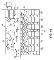
- FIG. 1 shows the schematic structure of the sheet processing apparatus 1 (hereinafter, referred to processor 1) in a first embodiment.
- Processor 1 has a classification/stacking unit 2, a banding unit 3 (a third unit) and an operation display panel 4.
- Classification/stacking unit 2 has an upper unit 2a (a first unit) and a lower unit 2b(a second unit). These units 2a, 2b and 3 have a conveying mechanism to convey sheets independently.
- Operation display panel 4 has a touch panel to accept an input operation when operator touches display buttons, and accepts various operational inputs by operator and displays various operational guides for operator.
- Each of units 2a, 2b and 3 of processor 1 operates according to work contents that are input and set by operator through operation display unit 4.
- Upper unit 2a has a feeding portion 11 that accepts sheets input for process and feeds sheets one by one on a main transport path 6.
- Main transport path 6 is extending to a classification/stacking portion 20 of lower unit 2b passing through classification/stacking unit 2.
- Main transport path 6 is defined basically by three sets of conveyor belts 7a and 7b which are opposed to each other so as to put main transport path between them as shown in FIG. 2 and FIG. 3.
- Three sets of conveyor belts 7a and 7b are arranged side by side apart each other in the width direction crossing the conveying direction of sheets and divided properly along main transport path 6.
- conveyor belts 7a and 7b of an upper unit 21 and conveyor belts 7a and 7b of lower unit 2b are divided at the boundary portion of upper and lower units 2a and 2b, and are driven by separate driving motors. Further, sheets are held and conveyed by three sets of conveyor belts 7a and 7b in the posture with the shorter sides directed in the conveying direction.
- main transport path 6 extending passing through upper unit 2a and lower unit 2b, there are a alignment portion 12, an detection portion 13, conveyor gates G1, G2 and G3, and five gates 14a to 14e in order.
- Three conveyor gates G1, G2 and G3 and five gates 14a to 14e are switched by a controller 60, which will be described later, based on the result of detection by detection portion 13.
- Alignment portion 12 is equipped with plural sensors (not illustrated) that detect the conveying posture of sheets taken out on main transport path 6 by feeding portion 11 and a correction mechanism (not illustrated) that corrects the conveying posture of the taken-out sheets based on the detection results of these plural sensors.
- Detecting portion 13 has plural sensors (not illustrated) to detects characteristics of sheets of which conveying postures are corrected by alignment portion 12 and a judging portion (not illustrated) to judge conveying destinations of sheets based on characteristics detected from the taken-out sheets by these plural sensors.
- Various kinds of characteristics are tear, stain, bend, right or false, conveying form, conveying direction, kinds of sheets and the like.
- Conveyor gate G1 is switched to selectively lead sheets being conveyed on main transport path 6 to rejection portion 16. Sheets that were judged to be rejected by detection portion 13 out of those sheets taken out on main transport path 6 by feeding portion 11 are sent into rejection portion 16.
- Conveyor gate G2 is switched to selectively direct sheets being conveyed on main transport path 6 toward reversing transport path 6a.
- Reversing transport path 6a has a structure to twist above-mentioned conveyor belts 7a and 7b by 180° along their running directions and reverses both sides of sheets. Sheets to bypass reversing transport path 6 pass through bypassing path 6b.
- Conveyor gate G3 provided near the exit of upper unit 2a functions as a diverging gate of this invention to branch main transport path 6 to diverging path 8 that will be described later. Diverging path 8 is extending almost horizontally by passing through banding unit 3 that will be described later.
- classifying/stacking portions 20a to 20f as sheet stacking destinations by gates 14a to 14e.
- First classifying/stacking portion 20a is provided corresponding to gate 14a provided at the most upper stream side along main transport path 6.
- Second classifying/stacking portion 20b is provided corresponding to second gate 14b.
- Third classifying/stacking portion 20c is provided corresponding to third gate 14c.
- Fourth classifying/stacking portion 20d is provided corresponding to fourth gate 14d.
- Fifth classifying/stacking portion 20e and sixth classifying/stacking portion 20f are provided corresponding to fifth gate 14e.
- First to sixth classifying/stacking portions 20a to 20f (hereinafter, may be called classifying/stacking portion 20 generically) have temporal stacking portion 21 for temporarily stacking sheets diverged from main transport path through corresponding gates 14a to 14e (hereinafter, may be called gate 14 generically), shutter 22 provided at the bottom of temporal stacking portion 21, cassette 23 for receiving sheets dropping from temporal stacking portion 21 through shutter 22, and pusher 24 provided above temporal stacking portion 21, respectively.
- Pusher 24 functions to push sheets in temporal stacking portion 21 into cassette 23 through shutter 22.
- each cassette 23 is provided to lower unit 2b detachably and can be removed from lower unit 2b manually by operator.
- a diverging path 8 extending through banding unit 3
- two gates 26a and 26b are provided on a diverging path 8 extending through banding unit 3.
- stacking portions 27a and 26b are provided corresponding to gates 26a and 27b.
- banding portion 29 for receiving sheets stacked in each stacking portion and banding for specified number of sheets.
- sheets stacked in stacking portions 27a and 27b are banded for every 100 sheets with a paper strip by banding portion 29.
- safety pocket 30 (a rejection pocket) that will be described later, on sidewall 3a at the wall separated from classifying/stacking unit 2 of banding unit 3.
- Safety pocket 30 functions as a rejecting portion of this invention jointly with above-mentioned conveyor gate G3.
- banding unit 3 is connected detachably to classifying/stacking unit 2, and conveyor belts 7a and 7b provided on diverging path 8 are also driven by driving motors other than driving motors for conveyor belts 7a and 7b provided on main transport path 6.
- sensors 31 to 51 are provided for detecting the passing of sheets and monitoring the conveying position and conveying state of sheets.
- Nine sensors 31 to 39 arrange on main transport path 6 extending by passing through upper unit 2a function as first detecting portions of this invention and 12 sensors 40 to 51 arranged on main transport path 6 extending by passing through lower unit 2b functions as second detecting portions of this invention.
- FIG. 2 is a side view of sensor 31 viewed from one side of main transport path 6, and FIG. 3 is a sectional view of sensor 31 and 3 sets of conveyor belts 7a and 7b.
- Sensor 31 has 2 sets of light emitting portion 31a and light receiving portion 31b with main transport path 6 put between.
- Light emitting portion 31a and light receiving portion 31b are attached to supporter 31c that is made of slender bent plate shape material.
- supporter 31c At the specified positions of supporter 31c, holes 31d are formed for beam L emitted from each light emitting portion 31a to light receiving portion 31b to pass through.
- Sensors 31 are located at the positions where two beams L to cross main transport path 6 at two positions separated in the width direction of sheets and not interfere 3 sets of conveyor belts 7a and 7b.
- FIG. 4 is a cross sectional view showing the schematic structure of partially enlarged above-mentioned safety pocket 30.
- FIG. 4A shows the closed state of safety pocket 30 and
- FIG. 4B shows the opened state of safety pocket 30.
- Safety pocket 30 is attached to the sidewall of banding unit 3 through a hinge mechanism so as to be able to open or close.
- Safety pocket 30 is formed with a transparent material such as plastic and in the closed state as shown in FIG. 4A, the inside of the pocket can be visually seen.
- monitor camera 30a is arranged aslant above safety pocket 30 to constantly monitor its inside state.
- open/close sensor 30b is provided for detecting the open/close state of safety pocket 30.
- Open/close sensor 30b detects that safety pocket 30 is in the closed state by detecting projection 30c of safety pocket 30 in the banding unit 3 through side wall 3a in the closed state of safety pocket 30 as shown in FIG. 4A.
- sensor 30b detects safety pocket 30 in the open state as shown in FIG.
- controller 60 controls first driving motor M1 (the first conveying mechanism) for driving conveyor belts 7a and 7b provided along main transport path 6 in upper unit 2a, second driving motor M2 (the second conveying mechanism) for driving conveyor belts 7a and 7b provided along main transport path 6 in lower unit 2b and third driving motor M3 (the third conveying mechanism) for driving conveyor belts 7a and 7b provided along diverging path 8 in banding unit 3 to stop the operation, respectively.
- first driving motor M1 the first conveying mechanism
- second driving motor M2 the second conveying mechanism
- third driving motor M3 the third conveying mechanism
- Sheets that lost destinations when conveyor gate G3 was switched are stacked in safety pocket 30.
- conveyor gate G3 is switched to the initial position, that is, the posture to connect main transport path 6 to lower unit 2b and upper unit 2a is stopped for jamming of sheets, etc.
- sheets that may possibly be sent into lower unit 2b from upper unit 2a by inertia are rejected into safety pocket 30 by way of diverging path 8.
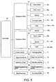
- FIG. 5 shows a block diagram of the control system to drive processor 1 described above.
- classifying/stacking unit 2 To controller 60 of processor 1, classifying/stacking unit 2, conveyor driver 62 of banding unit 3, feeder driver 63 to drive feeding portion 11, alignment driver 64 to drive alignment portion 12, detection driver 65 to control detection portion 13, classifying/stacking driver 66 to drive classifying/stacking portion 20, and banding driver 67 to driver banding portion 29 are connected.
- first driving motor M1 (the first conveying mechanism) to run plural conveyor belts 7a and 7b provided along main transport path 6 by passing through upper unit 2a
- second driving motor M2 (the second conveying mechanism) to run plural conveyor belts 7a and 7b provided along main transport path 6 extending by passing through lower unit 2b
- 21 sensors 31 to 51 3 conveyor gates G1, G2 and G3, and 5 gates 14a, 14b, 14c, 14d and 14e are connected.
- third driving motor M (the third conveying mechanism) to run plural conveyor belts 7a and 7b provided along diverging path 8 extending passing through banding unit 3 are connected. Further, conveyor driver 62 is connected with five sensors 52 to 56 and gates 26a and 26b provided on diverging path 8.
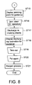
- Step 1 plural sheets that are subject to process are set in feeding portion 11 of upper unit 2a (Step 1), the work contents are set through operation/display panel, and the work task based on the set work contents starts (Step 2).
- Step 3 When the work task starts, the sheet feeding operation starts and plural sheets are taken out sequentially on main transport path 6 (Step 3).
- the sheets taken out on main transport path 6 pass through alignment portion 12 and the conveying posture is corrected (Step 4).
- various characteristic amounts are read by detection portion 13 and stacking portions in which sheets are to be stacked are judged by controller 60 (Step 5).
- Sheets assigned to classifying/stacking portion 20 for stacking are classified and stacked in classifying/stacking portion 20 by selectively switching gates 14a to 14d based on the work content that is set through operation/display panel 4 and the result of detection by detecting portion 13 (Step 7). Then, when specified number of sheets are stacked in temporal stacking portion 21 (Step 8: YES), the number of sheets is counted, shutter 22 is opened, pusher 24 is operated and stacked sheets are stored in corresponding cassettes 23 (Step 9).
- sheets assigned with stacking portion 27 for stacking are classified and stacked in specified stacking portions 27a and 27b by selectively switching conveyor gate G3 and gates 26a and 26b (Step 10).
- Step 11 the counted 100 sheets are confirmed and are supplied to banding portion 29 and banded with a paper strip (Step 12).
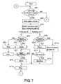
- controller 60 judges that conveying sheets are jammed in upper unit 2a.
- controller 60 stops the sheet conveying in upper unit 2a by stopping feeding portion 11 and driving motor M1 (Step 2), and at the same time, connects main transport path 6 to diverging path 8 by switching conveyor gate G3 (Step 3).
- Conveyor gate G3 is arranged at the position where it is able to orient sheets that may be sent to lower unit 2b from upper unit 2a by inertia of sheets toward diverging path 8 when main transport path 6 is connected to diverging path 8 at the timing described above. That is, at the time when upper unit 2a is stopped to operate, even when conveyor gate G3 is oriented to lower unit 2b, sheets in upper unit 2a are not sent to lower unit 2b by inertia. Further, conveyor gate G3 is switched to a posture to connect upper unit 2a and lower unit 2b in the initial state.
- controller 60 After stopping upper unit 2a in Step 2, controller 60 continues the process by lower unit 2b and checks the conveying timing of all sheets conveyed in lower unit 2b (Step 4). Then, controller 60 stacks sheets conveyed at a normal timing (Step 4: NO) in pre-assigned specified temporal stacking portion 21 (Step 5).
- controller 60 judges that sheets being conveyed is behind the timing in Step 4 (Step 4: YES)
- controller 60 judges that the sheets being conveyed are in an abnormal state for some reason, and stops lower unit 2b by stopping driving motor M2 (Step 6) and completes the process. In this case, after lower unit 2b is stopped, all sheets stacked in temporal stacking portion 21 are taken out for re-processing.
- controller 60 stores all sheets stacked in temporal stacking portion in corresponding cassette 23 by operating pusher 24 (Step 8) and completes the process.
- controller 60 continues the process of banding unit 3 after stopping upper unit 2a in Step 2, checks the conveying timing of all sheets conveyed in banding unit 3 (Step 9) and stacks sheets conveyed at a normal timing (Step 9; NO) in specified stacking portions 27a, 27b (Step 10). At this time, when the number of stacked sheets reaches 100 sheets (Step 11; YES), controller 60 sends 100 sheets to banding portion 29 for banding with a paper strip (Step 12).
- Step 9 sheets judged to be behind the conveying timing in Step 9 (Step 9; YES) are passed gates 26a and 26b on diverging path 8 directly and stacked in safety pocket 30 (Step 13).
- controller 60 stops lower unit 2b and banding unit 3 (Step 14) and displays a point where the jamming is caused on operation/display panel 4 for guidance (Step 15). On this display for guidance, a jamming point is graphically displayed based on the outputs of plural sensors 31 to 56.
- Step 16 Operator checks this guidance display and executes the jam clean for operation manually (Step 16). In this jamming process, operator removes jammed sheets by opening the cover of upper unit 2a.
- controller 60 drives all driving motors M1 to M3 and discharges all sheets remaining in processor 1 (Step 17). At this time, destinations of discharging sheets become rejection box 16 of upper unit 2a, temporal stacking portion 21 at the most downstream in the conveying direction of lower unit 2b and/or safety pocket 30.
- controller 60 displays destinations of sheets on operation/display panel 4 as the guidance for operator (Step 18). Operator checks this display guidance and feeds sheets discharged in temporal stacking portion 21 and/or safety pocket 30 (Step 19).
- Sheets thus taken out from processor 1 are put into processor 1 again through feeding portion 11 (Step 20) manually by operator and reprocessed based on an instruction input by operator through operation/display panel (for instance, a start key) (Step 21). At this time, the sheets taken out from processor 1 by operator in Step 16 are also put in processor 1 at the same time.
- controller 60 judges that the jamming was caused in lower unit 2b. In this case, controller 60 stops driving motors M1, M2 and stops the conveying of all sheets in classifying/stacking unit 2 (upper unit 2a and lower unit 2b) (Step 23).
- controller 60 continues the process of banding unit 3 and shifting to the process in Step 9, checks the conveying timing of all sheets conveyed in banding unit 3 (Step 9).
- the process hereafter is the same as the process described above and its explanation will be omitted here.
- controller 60 judges that the sheet jamming was caused in banding unit 3. In this case, controller 60 stops driving motors M1, M3 and stops the conveying of all sheets in upper unit 2a and banding unit 3 (Step 25) and at the same time, connects main transport path 6 to diverging 8 by switching conveyor gate G3 (Step 26).
- controller 60 continues the process by lower unit 2b and shifting to the process in Step 4 described above, checks the conveying timing of all sheets conveyed into lower unit 2b (Step 4).
- Step 4 the process is the same as that described above and therefore, will be omitted here.
- FIG. 10 shows the schematic structure of sheet processing apparatus 70 in the second embodiment of this invention.
- This processor 70 is not provided with banding unit 3 but is equipped with safety pocket 30 in classifying/stacking unit 2. All other portions are the same as those of processor 1 in the first embodiment. Therefore, the component elements that function similarly to those elements of processor 1 are assigned with the same reference numerals.
- this processor 70 when the jamming of conveying sheets is detected through sensors 31 to 39, it is judged that the jamming was caused in upper unit 2a, feeding portion 11 is stopped, driving motor M1 is stopped and the sheet conveying by upper unit 2a is stopped. At this time, the sheet process by lower unit 2b is continued and sheets are stacked in pre-assigned specified temporary stacking portion 21.
- FIG. 11 shows processor 80 in the third embodiment of this invention.
- the internal structures of units 2a, 2b, 3 and 3' are omitted.
- This processor 80 has two banding units 3 and 3' in the same structure arranged side by side along diverging path 8 (not illustrated here) and safety pocket 30 is installed to bending unit 3' at the downstream side in the conveying direction. All other structures are the same as those of processor 1 described above.
- this processor 80 when, for instance, the jamming is caused in banding unit 3 at the upper stream side in the conveying direction, the process in lower unit 2b is continued and the process in banding unit 3' of the downstream side in the conveying direction is also continued. Further, when more than 3 banding units 3, 3', 3" ... are provided, the process by banding units at downstream side in the conveying direction lower than a banding unit wherein the jamming is caused is continued similarly.
- this invention is applicable to processor 80 equipped with plural banding units and the same effect as the embodiments described above can be obtained.
- the sheet processing apparatus of this invention is in the structure and has functions as described above and is able to make error process such as sheet conveying jam certainly and easily.
Applications Claiming Priority (2)
| Application Number | Priority Date | Filing Date | Title |
|---|---|---|---|
| JP2003012595A JP2004224481A (ja) | 2003-01-21 | 2003-01-21 | 紙葉類処理装置 |
| JP2003012595 | 2003-01-21 |
Publications (3)
| Publication Number | Publication Date |
|---|---|
| EP1445660A2 true EP1445660A2 (de) | 2004-08-11 |
| EP1445660A3 EP1445660A3 (de) | 2007-12-05 |
| EP1445660B1 EP1445660B1 (de) | 2011-03-23 |
Family
ID=32652809
Family Applications (1)
| Application Number | Title | Priority Date | Filing Date |
|---|---|---|---|
| EP03030010A Expired - Lifetime EP1445660B1 (de) | 2003-01-21 | 2003-12-30 | Blattverarbeitungsvorrichtungen und Verfahren zur Blattgutverarbeitung |
Country Status (6)
| Country | Link |
|---|---|
| US (2) | US7017902B2 (de) |
| EP (1) | EP1445660B1 (de) |
| JP (1) | JP2004224481A (de) |
| CN (1) | CN100333982C (de) |
| AT (1) | ATE502885T1 (de) |
| DE (1) | DE60336450D1 (de) |
Cited By (1)
| Publication number | Priority date | Publication date | Assignee | Title |
|---|---|---|---|---|
| EP1905711A1 (de) * | 2006-09-29 | 2008-04-02 | Kabushiki Kaisha Toshiba | Blattverarbeitungsvorrichtung und Blattverarbeitungsverfahren |
Families Citing this family (28)
| Publication number | Priority date | Publication date | Assignee | Title |
|---|---|---|---|---|
| JP2004224481A (ja) * | 2003-01-21 | 2004-08-12 | Toshiba Corp | 紙葉類処理装置 |
| JP2005055868A (ja) * | 2003-07-22 | 2005-03-03 | Konica Minolta Business Technologies Inc | 画像形成装置 |
| JP2005221518A (ja) * | 2004-02-03 | 2005-08-18 | Oki Data Corp | 画像形成装置 |
| JP4346474B2 (ja) * | 2004-03-02 | 2009-10-21 | 日立オムロンターミナルソリューションズ株式会社 | 紙幣処理装置 |
| JP4772331B2 (ja) | 2005-01-20 | 2011-09-14 | 株式会社東芝 | 紙葉類処理装置 |
| JP5042559B2 (ja) * | 2006-08-10 | 2012-10-03 | 日立オムロンターミナルソリューションズ株式会社 | 紙葉類取扱装置 |
| US7484731B2 (en) * | 2006-08-28 | 2009-02-03 | Hewlett-Packard Development Company, L.P. | Printing device and method |
| JP5311743B2 (ja) * | 2007-01-18 | 2013-10-09 | キヤノン株式会社 | 印刷装置及びその制御方法、並びにプログラム |
| US9147301B2 (en) * | 2007-02-08 | 2015-09-29 | Glory Ltd. | Paper sheet handling machine |
| US8052144B2 (en) * | 2007-08-07 | 2011-11-08 | Ricoh Company, Ltd. | Method, apparatus, and system for forming image |
| JP4940060B2 (ja) * | 2007-08-24 | 2012-05-30 | 株式会社リコー | 用紙搬送装置、用紙処理装置及び画像形成装置 |
| TWM328379U (en) * | 2007-09-05 | 2008-03-11 | Lite On Technology Corp | Sheet feeding mechanism with duplex print function and printer thereof |
| US20100164171A1 (en) * | 2008-12-30 | 2010-07-01 | Konica Minolta Systems Laboratory, Inc. | Method and apparatus for clearing paper jam in a printing device |
| JP5258598B2 (ja) * | 2009-01-28 | 2013-08-07 | キヤノン株式会社 | 画像形成装置 |
| US20110296802A1 (en) * | 2009-02-27 | 2011-12-08 | Takayoshi Yano | Banknote sorting and bundling apparatus |
| CN102362296B (zh) * | 2009-03-26 | 2015-04-29 | 光荣株式会社 | 纸币分类捆扎处理装置以及纸币分类累积设定方法 |
| US8567156B2 (en) * | 2009-06-15 | 2013-10-29 | Kabushiki Kaisha Toshiba | Paper sheet processing system |
| DE102010004580A1 (de) * | 2010-01-14 | 2011-07-21 | WINCOR NIXDORF International GmbH, 33106 | Vorrichtung zur Handhabung von Wertscheinen mit einer Transportpfadüberwachung |
| US20110182644A1 (en) * | 2010-01-28 | 2011-07-28 | Kabushiki Kaisha Toshiba | Image forming apparatus and display control method |
| JP5691430B2 (ja) * | 2010-11-19 | 2015-04-01 | 沖電気工業株式会社 | 紙幣処理装置 |
| JP5755541B2 (ja) * | 2011-09-21 | 2015-07-29 | 株式会社東芝 | 紙葉類処理装置 |
| EP2568445A1 (de) | 2011-09-07 | 2013-03-13 | Kabushiki Kaisha Toshiba | Vorrichtung zur Papierblatthandhabung |
| JP2014117883A (ja) * | 2012-12-17 | 2014-06-30 | Canon Inc | 印刷装置、印刷装置の制御方法およびプログラム |
| JP6201230B2 (ja) * | 2013-04-26 | 2017-09-27 | グローリー株式会社 | 投票用紙分類機 |
| JP6514949B2 (ja) * | 2015-04-23 | 2019-05-15 | 日立オートモティブシステムズ株式会社 | オンチップノイズ保護回路を有する半導体チップ |
| US10037644B2 (en) * | 2015-06-16 | 2018-07-31 | Diebold Nixdorf, Incorporated | Automated banking machine cassette and cassette module |
| JP6858010B2 (ja) * | 2016-12-09 | 2021-04-14 | 株式会社東芝 | 後処理装置及び制御方法 |
| CN110288763B (zh) * | 2018-03-13 | 2021-05-07 | 山东新北洋信息技术股份有限公司 | 一种纸币排错方法及现金循环处理设备 |
Citations (4)
| Publication number | Priority date | Publication date | Assignee | Title |
|---|---|---|---|---|
| DE2916119A1 (de) * | 1978-04-21 | 1979-10-31 | Ricoh Kk | Elektrostatisches kopiergeraet |
| JPS60218247A (ja) * | 1984-04-13 | 1985-10-31 | Fuji Xerox Co Ltd | 複写機の用紙搬送系 |
| US5963755A (en) * | 1995-04-17 | 1999-10-05 | Canon Kabushiki Kaisha | Printing apparatus and control device for option equipment connected thereto |
| JP2001093026A (ja) * | 1999-09-20 | 2001-04-06 | Toshiba Corp | 紙葉類処理装置及び紙葉類処理方法 |
Family Cites Families (19)
| Publication number | Priority date | Publication date | Assignee | Title |
|---|---|---|---|---|
| JPS5574680A (en) * | 1978-11-30 | 1980-06-05 | Tokyo Shibaura Electric Co | Paper item treatment unit |
| JPS5627490A (en) * | 1979-08-09 | 1981-03-17 | Tokyo Shibaura Electric Co | Paper document classifier |
| JPS5644991A (en) * | 1979-09-21 | 1981-04-24 | Tokyo Shibaura Electric Co | Document handling machine |
| DE3606235A1 (de) * | 1985-02-28 | 1986-09-04 | Glory Kogyo K.K., Himeji, Hyogo | Banknoten-sortier- und zaehl-geraet |
| JP2507326B2 (ja) * | 1986-06-17 | 1996-06-12 | 株式会社東芝 | 結束装置付集計機 |
| US5464099A (en) * | 1986-09-05 | 1995-11-07 | Opex Corporation | Method for the automated processing of documents and bulk mail |
| JPS63177289A (ja) * | 1987-01-19 | 1988-07-21 | 株式会社東芝 | 紙葉類処理装置 |
| US5035412A (en) * | 1988-02-03 | 1991-07-30 | Canon Kabushiki Kaisha | Control method for a sorter |
| US5247159A (en) * | 1990-11-22 | 1993-09-21 | Kabushiki Kaisha Toshiba | Bill depositing/withdrawing system of the circulation type |
| JPH07309496A (ja) * | 1994-05-16 | 1995-11-28 | Riso Kagaku Corp | 印刷機の排紙装置 |
| US6860375B2 (en) * | 1996-05-29 | 2005-03-01 | Cummins-Allison Corporation | Multiple pocket currency bill processing device and method |
| US6460705B1 (en) * | 2000-08-09 | 2002-10-08 | Cummins-Allison Corp. | Method of creating identifiable smaller stacks of currency bills within a larger stack of currency bills |
| EP1785954B1 (de) * | 2000-03-23 | 2016-11-30 | Kabushiki Kaisha Toshiba | Umkehrungs- und Ausrichtungsmechanismus für Blattgutverarbeitungsvorrichtung |
| JP3878791B2 (ja) * | 2000-05-02 | 2007-02-07 | 日立オムロンターミナルソリューションズ株式会社 | 媒体処理装置 |
| JP2001344635A (ja) * | 2000-06-02 | 2001-12-14 | Birukon Kk | 紙葉類識別計数機およびその識別計数方法 |
| JP2002087678A (ja) * | 2000-09-19 | 2002-03-27 | Toshiba Corp | 紙葉類処理装置 |
| JP3604642B2 (ja) * | 2001-03-30 | 2004-12-22 | 八洲電研株式会社 | 遊技場における紙幣搬送装置 |
| JP2002316745A (ja) * | 2001-04-20 | 2002-10-31 | Toshiba Corp | 紙葉類処理装置 |
| JP2004224481A (ja) * | 2003-01-21 | 2004-08-12 | Toshiba Corp | 紙葉類処理装置 |
-
2003
- 2003-01-21 JP JP2003012595A patent/JP2004224481A/ja active Pending
- 2003-12-30 AT AT03030010T patent/ATE502885T1/de active
- 2003-12-30 DE DE60336450T patent/DE60336450D1/de not_active Expired - Lifetime
- 2003-12-30 EP EP03030010A patent/EP1445660B1/de not_active Expired - Lifetime
-
2004
- 2004-01-09 US US10/753,457 patent/US7017902B2/en not_active Expired - Lifetime
- 2004-01-20 CN CNB2004100025113A patent/CN100333982C/zh not_active Expired - Lifetime
-
2005
- 2005-09-19 US US11/228,249 patent/US7386964B2/en active Active
Patent Citations (4)
| Publication number | Priority date | Publication date | Assignee | Title |
|---|---|---|---|---|
| DE2916119A1 (de) * | 1978-04-21 | 1979-10-31 | Ricoh Kk | Elektrostatisches kopiergeraet |
| JPS60218247A (ja) * | 1984-04-13 | 1985-10-31 | Fuji Xerox Co Ltd | 複写機の用紙搬送系 |
| US5963755A (en) * | 1995-04-17 | 1999-10-05 | Canon Kabushiki Kaisha | Printing apparatus and control device for option equipment connected thereto |
| JP2001093026A (ja) * | 1999-09-20 | 2001-04-06 | Toshiba Corp | 紙葉類処理装置及び紙葉類処理方法 |
Cited By (1)
| Publication number | Priority date | Publication date | Assignee | Title |
|---|---|---|---|---|
| EP1905711A1 (de) * | 2006-09-29 | 2008-04-02 | Kabushiki Kaisha Toshiba | Blattverarbeitungsvorrichtung und Blattverarbeitungsverfahren |
Also Published As
| Publication number | Publication date |
|---|---|
| DE60336450D1 (de) | 2011-05-05 |
| JP2004224481A (ja) | 2004-08-12 |
| US20060006594A1 (en) | 2006-01-12 |
| CN100333982C (zh) | 2007-08-29 |
| ATE502885T1 (de) | 2011-04-15 |
| US7017902B2 (en) | 2006-03-28 |
| US20040144695A1 (en) | 2004-07-29 |
| EP1445660A3 (de) | 2007-12-05 |
| CN1517287A (zh) | 2004-08-04 |
| EP1445660B1 (de) | 2011-03-23 |
| US7386964B2 (en) | 2008-06-17 |
Similar Documents
| Publication | Publication Date | Title |
|---|---|---|
| US7386964B2 (en) | Sheet processing apparatus capable of processing conveying jam | |
| US10593142B2 (en) | Paper sheet processing system and paper sheet processing method | |
| US9786112B2 (en) | Paper sheet handling machine | |
| EP2782076B1 (de) | Blattverarbeitungsverfahren, Blattverarbeitungsvorrichtung und Blattverarbeitungssystem | |
| US7438289B2 (en) | Sheet material stacking apparatus | |
| US8246036B2 (en) | Paper sheet handling machine | |
| JP6198929B2 (ja) | 紙葉類処理装置 | |
| JP2503993B2 (ja) | 紙葉類の処理装置 | |
| JPH10162195A (ja) | 紙葉類処理装置、紙葉類裁断装置、および紙葉類処理方法 | |
| JP2567000B2 (ja) | 紙葉類集積装置 | |
| US20060070632A1 (en) | Segregating foreign objects from a stream of tobacoo | |
| JPH0930707A (ja) | 紙葉類分岐搬送装置 | |
| JP2003276904A (ja) | 紙葉類処理装置 | |
| JP2540969B2 (ja) | 紙幣帯封装置の紙幣送り制御方式 | |
| JP2002087678A (ja) | 紙葉類処理装置 | |
| JPH08190655A (ja) | 紙葉類処理装置 | |
| JPH08231082A (ja) | 紙葉類取扱装置 | |
| JP2005059972A (ja) | 紙葉類処理装置 | |
| JPS6235713B2 (de) | ||
| JP2001031310A (ja) | 紙葉類処理装置 | |
| JPH08192826A (ja) | 券類搬送施封装置 | |
| JPH01176749A (ja) | 紙葉類処理装置 | |
| JPH08175700A (ja) | 紙葉類搬送装置 | |
| JPS62126082A (ja) | 紙葉類搬送区分装置 | |
| JPH0725512A (ja) | 紙葉類取扱装置 |
Legal Events
| Date | Code | Title | Description |
|---|---|---|---|
| PUAI | Public reference made under article 153(3) epc to a published international application that has entered the european phase |
Free format text: ORIGINAL CODE: 0009012 |
|
| 17P | Request for examination filed |
Effective date: 20031230 |
|
| AK | Designated contracting states |
Kind code of ref document: A2 Designated state(s): AT BE BG CH CY CZ DE DK EE ES FI FR GB GR HU IE IT LI LU MC NL PT RO SE SI SK TR |
|
| AX | Request for extension of the european patent |
Extension state: AL LT LV MK |
|
| PUAL | Search report despatched |
Free format text: ORIGINAL CODE: 0009013 |
|
| AK | Designated contracting states |
Kind code of ref document: A3 Designated state(s): AT BE BG CH CY CZ DE DK EE ES FI FR GB GR HU IE IT LI LU MC NL PT RO SE SI SK TR |
|
| AX | Request for extension of the european patent |
Extension state: AL LT LV MK |
|
| RIC1 | Information provided on ipc code assigned before grant |
Ipc: B65H 7/20 20060101AFI20071026BHEP Ipc: G03G 15/00 20060101ALI20071026BHEP |
|
| AKX | Designation fees paid |
Designated state(s): AT DE FR GB IT |
|
| 17Q | First examination report despatched |
Effective date: 20100408 |
|
| GRAP | Despatch of communication of intention to grant a patent |
Free format text: ORIGINAL CODE: EPIDOSNIGR1 |
|
| GRAS | Grant fee paid |
Free format text: ORIGINAL CODE: EPIDOSNIGR3 |
|
| GRAA | (expected) grant |
Free format text: ORIGINAL CODE: 0009210 |
|
| AK | Designated contracting states |
Kind code of ref document: B1 Designated state(s): AT DE FR GB IT |
|
| REG | Reference to a national code |
Ref country code: GB Ref legal event code: FG4D |
|
| REF | Corresponds to: |
Ref document number: 60336450 Country of ref document: DE Date of ref document: 20110505 Kind code of ref document: P |
|
| REG | Reference to a national code |
Ref country code: DE Ref legal event code: R096 Ref document number: 60336450 Country of ref document: DE Effective date: 20110505 |
|
| PLBE | No opposition filed within time limit |
Free format text: ORIGINAL CODE: 0009261 |
|
| STAA | Information on the status of an ep patent application or granted ep patent |
Free format text: STATUS: NO OPPOSITION FILED WITHIN TIME LIMIT |
|
| 26N | No opposition filed |
Effective date: 20111227 |
|
| REG | Reference to a national code |
Ref country code: DE Ref legal event code: R097 Ref document number: 60336450 Country of ref document: DE Effective date: 20111227 |
|
| PG25 | Lapsed in a contracting state [announced via postgrant information from national office to epo] |
Ref country code: IT Free format text: LAPSE BECAUSE OF FAILURE TO SUBMIT A TRANSLATION OF THE DESCRIPTION OR TO PAY THE FEE WITHIN THE PRESCRIBED TIME-LIMIT Effective date: 20110323 |
|
| REG | Reference to a national code |
Ref country code: FR Ref legal event code: PLFP Year of fee payment: 13 |
|
| REG | Reference to a national code |
Ref country code: FR Ref legal event code: PLFP Year of fee payment: 14 |
|
| REG | Reference to a national code |
Ref country code: FR Ref legal event code: PLFP Year of fee payment: 15 |
|
| PGFP | Annual fee paid to national office [announced via postgrant information from national office to epo] |
Ref country code: GB Payment date: 20221110 Year of fee payment: 20 Ref country code: FR Payment date: 20221110 Year of fee payment: 20 Ref country code: DE Payment date: 20220622 Year of fee payment: 20 Ref country code: AT Payment date: 20221125 Year of fee payment: 20 |
|
| REG | Reference to a national code |
Ref country code: DE Ref legal event code: R071 Ref document number: 60336450 Country of ref document: DE |
|
| PG25 | Lapsed in a contracting state [announced via postgrant information from national office to epo] |
Ref country code: GB Free format text: LAPSE BECAUSE OF EXPIRATION OF PROTECTION Effective date: 20231229 |
|
| REG | Reference to a national code |
Ref country code: GB Ref legal event code: PE20 Expiry date: 20231229 |
|
| PG25 | Lapsed in a contracting state [announced via postgrant information from national office to epo] |
Ref country code: GB Free format text: LAPSE BECAUSE OF EXPIRATION OF PROTECTION Effective date: 20231229 |
|
| REG | Reference to a national code |
Ref country code: AT Ref legal event code: MK07 Ref document number: 502885 Country of ref document: AT Kind code of ref document: T Effective date: 20231230 |