EP1400317A1 - Zusatzhandgriff - Google Patents
Zusatzhandgriff Download PDFInfo
- Publication number
- EP1400317A1 EP1400317A1 EP02020927A EP02020927A EP1400317A1 EP 1400317 A1 EP1400317 A1 EP 1400317A1 EP 02020927 A EP02020927 A EP 02020927A EP 02020927 A EP02020927 A EP 02020927A EP 1400317 A1 EP1400317 A1 EP 1400317A1
- Authority
- EP
- European Patent Office
- Prior art keywords
- handle according
- additional handle
- area
- grip
- handle
- Prior art date
- Legal status (The legal status is an assumption and is not a legal conclusion. Google has not performed a legal analysis and makes no representation as to the accuracy of the status listed.)
- Granted
Links
Images

Classifications
-
- B—PERFORMING OPERATIONS; TRANSPORTING
- B25—HAND TOOLS; PORTABLE POWER-DRIVEN TOOLS; MANIPULATORS
- B25F—COMBINATION OR MULTI-PURPOSE TOOLS NOT OTHERWISE PROVIDED FOR; DETAILS OR COMPONENTS OF PORTABLE POWER-DRIVEN TOOLS NOT PARTICULARLY RELATED TO THE OPERATIONS PERFORMED AND NOT OTHERWISE PROVIDED FOR
- B25F5/00—Details or components of portable power-driven tools not particularly related to the operations performed and not otherwise provided for
- B25F5/006—Vibration damping means
-
- B—PERFORMING OPERATIONS; TRANSPORTING
- B25—HAND TOOLS; PORTABLE POWER-DRIVEN TOOLS; MANIPULATORS
- B25F—COMBINATION OR MULTI-PURPOSE TOOLS NOT OTHERWISE PROVIDED FOR; DETAILS OR COMPONENTS OF PORTABLE POWER-DRIVEN TOOLS NOT PARTICULARLY RELATED TO THE OPERATIONS PERFORMED AND NOT OTHERWISE PROVIDED FOR
- B25F5/00—Details or components of portable power-driven tools not particularly related to the operations performed and not otherwise provided for
- B25F5/02—Construction of casings, bodies or handles
- B25F5/025—Construction of casings, bodies or handles with torque reaction bars for rotary tools
- B25F5/026—Construction of casings, bodies or handles with torque reaction bars for rotary tools in the form of an auxiliary handle
Definitions
- the invention relates to an additional handle for releasable Fixation on a hand-held tool, in particular a Drill or chisel hammer.
- the auxiliary handle has a rod-shaped body on which a grip sleeve over elastic means is attached.
- the grip sleeve extends while concentric with the rod-shaped body.
- the rod-shaped design of the auxiliary handle requires a for some applications unfavorable hand position of the operator. The achievable damping effect is also often unsatisfactory.
- the invention is based on the object, an additional handle for releasably fixing to a hand-held tool to create a pleasant working attitude of the operator allows and a good damping behavior for vibrations having.
- the auxiliary handle has a mounting area with the a grip area via a vibration-damping, elastic Material is connected. Mounting area and handle area preferably form a closed frame. Of the Additional handle is thus designed as a bow handle. These Training as a bow handle with a largely closed Frame allows a comfortable working posture of the operator, because the tool can be guided laterally without a Twisting the operator's hand is necessary. simultaneously can over the closed frame of the auxiliary handle a good vibration damping can be achieved.
- the elastic material forms at least in Area of connection the surface of the auxiliary handle. Due to the arrangement of the elastic material also on the Surface can reach a large damping cross section become. This is especially enlarged compared to handles, in which vibration-damping elements in the handle interior are arranged.
- the attachment area and the Handle area expediently each have a largely dimensionally stable Body on.
- the dimensionally stable body improves the handling with regard to the guidance of the tool. Easy to manufacture and good vibration damping arises when both main body largely of surrounded by the elastic material.
- the elastic material is in particular a thermoplastic elastomer.
- the bow handle can handle the two areas be sprayed together with the elastic material. So The bow handle can be made in a few steps. At the same time the elastic material leads in the grip area to that the gripping of the auxiliary handle by the operator as is pleasant.
- the attachment area substantially is cylindrical.
- the grip area points in particular a substantially cylindrical handle portion on, which has two legs formed at its ends with the Attachment area is connected.
- This shape of the frame-shaped Additional handle allows a good guidance of the Tool with low transmitted vibrations. expedient the legs extend approximately perpendicular to the longitudinal axis of the Fastening area.
- the stop is advantageously by a finger connected to the main body formed, which is arranged in a recess, wherein the Recess of the other body is limited. Thereby a safe limitation of mobility is guaranteed. At the same time, such a trained stop well in the auxiliary handle are integrated. To the mobility the grip area opposite the mounting area in all To ensure and at the same time limit directions is provided that the finger at its entire circumference a distance to the recess. Improved damping properties are achieved when the distance is about 1 mm 10 mm, in particular 3 mm to 6 mm. It is advantageous each leg of the handle portion formed a stop.
- the attachment area via a strap on Tool fixable.
- the strap is appropriate in one Bracket arranged between two sections of the mounting area is held.
- the attachment area points expedient teeth on which in corresponding wells on the The holder of the tension band protrude.
- the protruding in depressions Teeth allow when arranged on the entire circumference that the between the handle area of the auxiliary handle and the tool formed angle is variable. So can the desired Position of the additional handle to be customized.
- the Bracket is advantageously made up of two jaws made by a clamping screw are penetrated, the jaws on the the clamping band opposite side of the clamping screw to each other issue.
- the clamping screw penetrates expediently the cylindrical mounting area. That's how it works Tensioning band can be tensioned in a simple way.
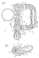
- auxiliary handle. 1 has a mounting area 2.
- a handle portion 3 is formed to the mounting area 2.
- the grip area 3 is formed in the embodiment bow-shaped and forms with the attachment region 2 a particular closed Frame.
- the grip area 3 has a grip portion 6, which is approximately cylindrical and parallel to cylindrical mounting portion 2 extends.
- At the ends 37 and 38 of the grip portion 6 are respectively legs 7 and 8 formed over which the handle portion 6 with the mounting portion 2 is connected.
- the first leg 7 has a Recess 12, in which a finger 10 protrudes.
- the second leg 8 has a recess 13 in which a finger 11 is arranged.
- Fingers 10 and 11 form stops for mobility of the attachment region 2 opposite the grip region 3
- Fastening region 2 has in the region of the connection to first leg 7 a thickening 39 and in the region of the connection to the second leg 8 a thickening 40.
- the mounting portion 2 is formed divided and has a first portion 16 connected to the first leg 7 is and a second, with the second leg. 8 associated section 17. Between Sections 16 and 17 a holder 18 is arranged for a strap 14.
- the Holder 18 has a toothing, which in a corresponding Teeth arranged on the sections 16 and 17 is.
- teeth 21 arranged on the first section 16 protrude in recesses 23 of the holder 18 and on the second section 17 molded teeth 22 in recesses 24 of the bracket 18th
- the toothing is concentric and allows so a change in the position of the tension band 14 to the attachment area 2.
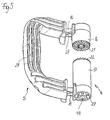
- a toggle nut 26 is disposed on the second leg 8. As the plan view in Fig. 2 shows, the leg 7 and also the leg 8 is arcuate.
- the attachment portion 2 is divided as shown in FIG educated. Between the first section 16 and the second section 17 is the holder 18 of the tension band 14 arranged.
- the holder 18 has a first jaw 19 and a second jaw 20.
- the mounting portion 2 is of a Clamping screw 25 protrudes, the head 43 in a hexagonal recess 41 is arranged.
- the hexagonal recess 41 is while in the region of the first leg 7 in the attachment area 2 arranged.
- the clamping screw 25 extends through the first section 16, the jaws 19 and 20 of the holder 18 and the second portion 17 of the attachment area 2.
- the toggle nut 26th is the toggle nut 26th arranged.
- the toggle nut 26 has an internal thread 42, in which the clamping screw 25 is screwed.
- the internal thread 42 is advantageous in one in the toggle nut 26th arranged metallic sleeve formed.
- the attachment area 2 has a largely dimensionally stable Basic body 4.
- the main body 4 is connected to the main body 5 of the handle portion 3 via an elastic material 34th connected.
- the elastic material 34 is in particular a thermoplastic elastomer.
- a finger 10 is disposed on the base body 4th of the fastening region 2 is formed.
- the finger 10 is in a recess 12 is arranged.
- a finger 11 is formed, in a recess 13 in the main body 5 of the Gripping area 3 is arranged.
- connection 36 between the basic bodies 4th and Fig. 5 is shown in section on the second leg 8.
- the finger 11 is integrally formed on the base body 4 and has to the main body 4 a distance a and a distance c in the circumferential direction the clamping screw 25.
- the main body 4 and 5 are in the region of the connection 36 only on the elastic material 34 connected. In the area of connection 36 If a thickening 40 of the elastic material 34 is formed, the good cushioning between the attachment area 2 and the grip area 3 guaranteed.
- Around Compounds 35, 36 forms the elastic material 34 the Surface of auxiliary handle 1.
- the finger 11 points in one direction parallel to the longitudinal axis 9 of the attachment area 2 a distance b or on the opposite side one Distance d to the grip area 4.
- the distances a, b, c, d can be the same size or different sizes.
- the distances a, b, c, d are advantageously about 1 mm to 10 mm, in particular 3 mm to 6 mm.
- the distance a and the distance c between 4 mm and 5 mm.
- the Attachment area 2 and the handle portion 3 of the elastic Material 34 are overmoulded.
- Fig. 5 shows the main body 4 and 5 without the elastic Material 34.
- the first base 4, which is the attachment area 2 has ribs 27 radially to the longitudinal axis 9.
- the molded on the sections 16 and 17 fingers 10 and 11th also have ribs 27 for reinforcement.
- the main body 5 of the handle portion 3 also has in each case in Longitudinal direction of the main body 5 extending ribs 27.
- the ribs 27 ensures that the base body 4 and 5 are stable.
- a good connection to the elastic material 34 are produced.
- the main body 5 the handle portion 3 and the two-part body formed 4 of the mounting portion 2 are as separate components educated. Through the sections 16 and 17 extends a central opening 44 through which the clamping screw 25, as shown in Fig. 3, projects.
- the teeth projecting towards each other 21 and 22 at the attachment area 3 are concentric around the Opening 44 arranged.
- the angle between the attachment area 3 and the clamping band 14 can by turning the tension band 14 about the longitudinal axis 9 of the attachment area. 2 be varied.
- the gearing ensures that mounting area 2 and tensioning strap 14 in operation, ie with tightened toggle nut 26, each other not movable are.
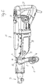
- an auxiliary handle 1 is shown, which is connected to a Tool 15 is attached.
- the tool 15 has a housing 28, to which a handle 29 is attached.
- a clamping device 33 is arranged in the a tool insert can be fixed.
- the tool 15 from the strap 14 of the auxiliary handle 1 includes.
- an opening 30 in the region of the handle 29 and a Opening 31, which faces the auxiliary handle 1 Side of the housing 28 is arranged.
- a stalk-shaped auxiliary handle can be arranged become.
Landscapes
- Engineering & Computer Science (AREA)
- Mechanical Engineering (AREA)
- Portable Power Tools In General (AREA)
Abstract
Description
- Fig. 1
- eine perspektivische Ansicht eines Zusatzhandgriffs,
- Fig. 2
- eine Ansicht auf den Zusatzhandgriff aus Fig. 1 von oben,
- Fig. 3
- einen Schnitt entlang der Linie III-III in Fig. 2,
- Fig. 4
- einen Schnitt entlang der Linie IV-IV in Fig. 3,
- Fig. 5
- eine perspektivische Ansicht auf die Grundkörper des Zusatzhandgriffs,
- Fig. 6
- eine perspektivische Ansicht eines Werkzeuges mit daran fixiertem Zusatzhandgriff.
Claims (17)
- Zusatzhandgriff zur lösbaren Fixierung an einem handgeführten Werkzeug, insbesondere einem Bohr- oder Meißelhammer, mit einem Befestigungsbereich (2) zur Fixierung am Werkzeug (15) und einem Griffbereich (3), der mit dem Befestigungsbereich (2) einen weitgehend geschlossenen Rahmen bildet und der mit dem Befestigungsbereich (2) über ein elastisches, vibrationsdämpfendes Material (34) verbunden ist.
- Zusatzhandgriff nach Anspruch 1,
dadurch gekennzeichnet, daß das elastische Material (34) mindestens im Bereich der Verbindung (35, 36) die Oberfläche des Zusatzhandgriffs (1) bildet. - Zusatzhandgriff nach Anspruch 1 oder 2,
dadurch gekennzeichnet, daß der Befestigungsbereich (2) und der Griffbereich (3) jeweils einen weitgehend formstabilen Grundkörper (4, 5) aufweisen. - Zusatzhandgriff nach Anspruch 3,
dadurch gekennzeichnet, daß mindestens ein Grundkörper (4, 5) weitgehend von dem elastischen Material (34) umgeben ist. - Zusatzhandgriff nach einem der Ansprüche 1 bis 4,
dadurch gekennzeichnet, daß das elastische Material (34) ein thermoplastisches Elastomer ist. - Zusatzhandgriff nach einem der Ansprüche 1 bis 5,
dadurch gekennzeichnet, daß der Befestigungsbereich (2) im wesentlichen zylindrisch ausgebildet ist. - Zusatzhandgriff nach einem der Ansprüche 1 bis 6,
dadurch gekennzeichnet, daß der Griffbereich (3) einen im wesentlichen zylindrischen Griffabschnitt (6) aufweist, der über zwei an seinen Enden (37, 38) angeformte Schenkel (7, 8) mit dem Befestigungsbereich (2) verbunden ist und mit dem Befestigungsbereich (2) einen geschlossenen Rahmen bildet. - Zusatzhandgriff nach Anspruch 7,
dadurch gekennzeichnet, daß die Schenkel (7, 8) sich etwa senkrecht zur Längsachse (9) des Befestigungsbereichs (2) erstrecken. - Zusatzhandgriff nach einem der Ansprüche 1 bis 8,
dadurch gekennzeichnet, daß die Beweglichkeit des Griffbereichs (3) gegenüber dem Befestigungsbereich (2) durch mindestens einen Anschlag begrenzt ist. - Zusatzhandgriff nach Anspruch 9,
dadurch gekennzeichnet, daß der Anschlag durch einen mit einem Grundkörper (4) verbundenen Finger (10, 11) gebildet ist, der in einer Aussparung (12, 13) angeordnet ist, wobei die Aussparung (12, 13) von dem anderen Grundkörper (5) begrenzt ist. - Zusatzhandgriff nach Anspruch 10,
dadurch gekennzeichnet, daß der Finger (10, 11) an seinem gesamten Umfang einen Abstand (a, b, c, d) zur Aussparung (12, 13) aufweist. - Zusatzhandgriff nach Anspruch 11,
dadurch gekennzeichnet, daß der Abstand (a, b, c, d) etwa 1 mm bis 10 mm, insbesondere 3 mm bis 6 mm beträgt. - Zusatzhandgriff nach einem der Ansprüche 7 bis 12,
dadurch gekennzeichnet, daß an jedem Schenkel (7, 8) des Griffbereichs (3) ein Anschlag gebildet ist. - Zusatzhandgriff nach einem der Ansprüche 1 bis 13,
dadurch gekennzeichnet, daß der Befestigungsbereich (2) über ein Spannband (14) am Werkzeug (15) fixierbar ist. - Zusatzhandgriff nach Anspruch 14,
dadurch gekennzeichnet, daß das Spannband (14) in einer Halterung (18) angeordnet ist, die zwischen zwei Abschnitten (16, 17) des Befestigungsbereich (2) gehalten ist. - Zusatzhandgriff nach Anspruch 15,
dadurch gekennzeichnet, daß der Befestigungsbereich (2) Zähne (21, 22) aufweist, die in entsprechende Vertiefungen (22, 23) an der Halterung (18) des Spannbands (14) ragen. - Zusatzhandgriff nach Anspruch 15 oder 16,
dadurch gekennzeichnet, daß die Halterung (18) aus zwei Backen (19, 20) gebildet ist, die von einer Spannschraube (25) durchragt sind, wobei die Backen (19, 20) auf der dem Spannband (14) gegenüberliegenden Seite der Spannschraube (25) aneinander anliegen.
Priority Applications (2)
| Application Number | Priority Date | Filing Date | Title |
|---|---|---|---|
| EP02020927.6A EP1400317B2 (de) | 2002-09-19 | 2002-09-19 | Zusatzhandgriff |
| DE50211364T DE50211364D1 (de) | 2002-09-19 | 2002-09-19 | Zusatzhandgriff |
Applications Claiming Priority (1)
| Application Number | Priority Date | Filing Date | Title |
|---|---|---|---|
| EP02020927.6A EP1400317B2 (de) | 2002-09-19 | 2002-09-19 | Zusatzhandgriff |
Publications (3)
| Publication Number | Publication Date |
|---|---|
| EP1400317A1 true EP1400317A1 (de) | 2004-03-24 |
| EP1400317B1 EP1400317B1 (de) | 2007-12-12 |
| EP1400317B2 EP1400317B2 (de) | 2014-03-05 |
Family
ID=31896880
Family Applications (1)
| Application Number | Title | Priority Date | Filing Date |
|---|---|---|---|
| EP02020927.6A Expired - Lifetime EP1400317B2 (de) | 2002-09-19 | 2002-09-19 | Zusatzhandgriff |
Country Status (2)
| Country | Link |
|---|---|
| EP (1) | EP1400317B2 (de) |
| DE (1) | DE50211364D1 (de) |
Cited By (24)
| Publication number | Priority date | Publication date | Assignee | Title |
|---|---|---|---|---|
| DE102005046227A1 (de) * | 2005-09-28 | 2007-04-05 | Andreas Stihl Ag & Co. Kg | Arbeitsgerät |
| GB2444156A (en) * | 2006-11-24 | 2008-05-28 | Bosch Gmbh Robert | An auxiliary handle for a hand held power tool with quick adjustment by a bayonet coupling |
| GB2444160A (en) * | 2006-11-24 | 2008-05-28 | Bosch Gmbh Robert | Auxiliary handle for a hand held machine tool with rapid adjustment by means of two threads |
| WO2008061837A1 (de) * | 2006-11-22 | 2008-05-29 | Robert Bosch Gmbh | Zusatzhandgriff mit exzenterspannhebel für eine handwerkzeugmaschine |
| EP1974867A1 (de) * | 2007-03-29 | 2008-10-01 | Makita Corporation | Griffe für Handwerkzeuge |
| US7484300B2 (en) | 2004-09-09 | 2009-02-03 | Black & Decker Inc. | Extensible pole saw having separable sections |
| EP2020279A1 (de) * | 2007-07-31 | 2009-02-04 | HILTI Aktiengesellschaft | Momenthebel |
| EP2087828A1 (de) * | 2008-02-07 | 2009-08-12 | Koninklijke Philips Electronics N.V. | Handgriffanordnung für eine Saugbefestigung |
| DE102009000598A1 (de) | 2008-02-15 | 2009-08-20 | Robert Bosch Gmbh | Schwingungsentkoppelter Handgriff |
| EP2163357A1 (de) * | 2008-09-15 | 2010-03-17 | HILTI Aktiengesellschaft | Zusatzhandgriff für eine Handwerkzeugmaschine |
| EP2135713A3 (de) * | 2008-06-17 | 2010-05-26 | Makita Corporation | Zusatzhandgriff |
| DE102008044117A1 (de) | 2008-11-27 | 2010-06-02 | Robert Bosch Gmbh | Zusatzhandgriffvorrichtung |
| DE102008044119A1 (de) | 2008-11-27 | 2010-06-02 | Robert Bosch Gmbh | Zusatzhandgriffvorrichtung |
| DE102008054459A1 (de) | 2008-12-10 | 2010-06-17 | Robert Bosch Gmbh | Zusatzhandgriffvorrichtung |
| EP1852224A3 (de) * | 2006-04-25 | 2010-06-23 | Leatherman Tool Group, Inc. | Handwerkzeug mit festen und drehbaren Elementen und damit verbundener Schließmechanismus |
| GB2444169B (en) * | 2006-11-24 | 2010-09-01 | Bosch Gmbh Robert | Auxiliary handle with quick adjustment and with wear-resistant rotation-prevention elements |
| ES2347396A1 (es) * | 2006-11-24 | 2010-10-28 | Robert Bsoch Gmbh | Mango auxiliar para una maquina herramienta con un ajuste rapido por sobreencajado. |
| WO2010136245A1 (de) * | 2009-05-29 | 2010-12-02 | Robert Bosch Gmbh | Zusatzhandgriffvorrichtung einer handwerkzeugmaschine |
| US8042220B2 (en) | 2005-09-28 | 2011-10-25 | Andreas Stihl Ag & Co. Kg | Implement |
| US8186018B2 (en) * | 2008-09-15 | 2012-05-29 | Hilti Aktiengesellschaft | Auxiliary handle for hand-held power tool |
| ITBL20130013A1 (it) * | 2013-08-09 | 2015-02-10 | Giuliano Sartor | Maniglia di bilanciamento perfezionata, particolarmente per una pala o simile attrezzo da lavoro manuale |
| WO2015019326A3 (en) * | 2013-08-09 | 2015-05-28 | Myour S.R.L. | Improved balancing hand grip for a hand tool |
| EP3034245A1 (de) * | 2014-12-19 | 2016-06-22 | HILTI Aktiengesellschaft | Zusatzhandgriff |
| EP4245468A1 (de) * | 2022-03-15 | 2023-09-20 | Hilti Aktiengesellschaft | Seitenhandgriff für eine elektrische handwerkzeugmaschine |
Families Citing this family (2)
| Publication number | Priority date | Publication date | Assignee | Title |
|---|---|---|---|---|
| DE102008028217B4 (de) | 2008-06-12 | 2015-06-18 | Minda Schenk Plastic Solutions Gmbh | Zusatzhandgriff an einem handgeführten Werkzeug |
| EP4313494A1 (de) | 2021-03-25 | 2024-02-07 | Milwaukee Electric Tool Corporation | Seitengriff für ein elektrowerkzeug |
Citations (4)
| Publication number | Priority date | Publication date | Assignee | Title |
|---|---|---|---|---|
| US4060940A (en) * | 1976-01-13 | 1977-12-06 | The Black And Decker Manufacturing Company | Adjustable guard construction for cut-off machine |
| US5157807A (en) * | 1990-04-06 | 1992-10-27 | Metabowerke Gmbh & Co. | Vibration-cushioned handle |
| DE4302676A1 (de) * | 1993-01-30 | 1994-08-04 | Bosch Gmbh Robert | Beidhändig geführtes Elektrohandwerkzeug mit Griffbügel |
| DE4406718A1 (de) * | 1994-02-25 | 1995-08-31 | Black & Decker Inc | Zusatzhandgriff für handgeführte Werkzeuge |
Family Cites Families (11)
| Publication number | Priority date | Publication date | Assignee | Title |
|---|---|---|---|---|
| FR715979A (fr) † | 1931-04-24 | 1931-12-12 | Nord De La France Et Des Murea | Perfectionnements aux appareils tenus à la main tels que marteaux pneumatiques, perforateurs, piqueurs et analogues |
| GB668687A (en) † | 1949-06-20 | 1952-03-19 | Lord Mfg Co | Cushion handle for percussive tool |
| JPS5946751B2 (ja) † | 1982-02-13 | 1984-11-14 | 株式会社エムエス技研 | 防振ハンドル装置 |
| DE3580380D1 (de) † | 1984-03-30 | 1990-12-13 | Makoto Minamidate | Schwingungsdaempfende griffvorrichtung. |
| DE8701722U1 (de) † | 1987-02-05 | 1987-04-09 | Weber Maschinentechnik Gmbh, 5928 Laasphe, De | |
| AU8303891A (en) † | 1990-07-19 | 1992-02-18 | Cabot Safety Corporation | Vibration damping handle grip and grip cover |
| SE467690B (sv) † | 1990-12-11 | 1992-08-31 | Atlas Copco Tools Ab | Vibrationsisolerat verktygshandtag |
| DE29701737U1 (de) † | 1997-02-01 | 1997-04-03 | Wacker Werke Kg | Verbindungseinrichtung zum abgefederten Verbinden einer Deichsel oder eines Führungsbügels an der Obermasse einer Vibrationsplatte |
| DE19848126A1 (de) † | 1998-10-19 | 2000-04-27 | Wilhelm Kaechele Gmbh Elastome | Schwingungsgedämpfter Handgriff |
| DE19925281B4 (de) † | 1999-06-02 | 2014-10-02 | Andreas Stihl Ag & Co. | Handgeführtes Arbeitsgerät, insbesondere Heckenschere mit vibrationsgedämpften Handgriffen |
| DE10106050B4 (de) † | 2001-02-09 | 2017-02-16 | Hilti Aktiengesellschaft | Handwerkzeugmaschine mit einem Zusatzhandgriff |
-
2002
- 2002-09-19 EP EP02020927.6A patent/EP1400317B2/de not_active Expired - Lifetime
- 2002-09-19 DE DE50211364T patent/DE50211364D1/de not_active Expired - Lifetime
Patent Citations (4)
| Publication number | Priority date | Publication date | Assignee | Title |
|---|---|---|---|---|
| US4060940A (en) * | 1976-01-13 | 1977-12-06 | The Black And Decker Manufacturing Company | Adjustable guard construction for cut-off machine |
| US5157807A (en) * | 1990-04-06 | 1992-10-27 | Metabowerke Gmbh & Co. | Vibration-cushioned handle |
| DE4302676A1 (de) * | 1993-01-30 | 1994-08-04 | Bosch Gmbh Robert | Beidhändig geführtes Elektrohandwerkzeug mit Griffbügel |
| DE4406718A1 (de) * | 1994-02-25 | 1995-08-31 | Black & Decker Inc | Zusatzhandgriff für handgeführte Werkzeuge |
Cited By (42)
| Publication number | Priority date | Publication date | Assignee | Title |
|---|---|---|---|---|
| US7484300B2 (en) | 2004-09-09 | 2009-02-03 | Black & Decker Inc. | Extensible pole saw having separable sections |
| DE102005046227A1 (de) * | 2005-09-28 | 2007-04-05 | Andreas Stihl Ag & Co. Kg | Arbeitsgerät |
| US7707684B2 (en) | 2005-09-28 | 2010-05-04 | Andreas Stihl Ag & Co. Kg | Implement having adjustable handle |
| DE102005046227B4 (de) * | 2005-09-28 | 2009-10-01 | Andreas Stihl Ag & Co. Kg | Arbeitsgerät mit Einhand- und Zeihandbedienung |
| US8042220B2 (en) | 2005-09-28 | 2011-10-25 | Andreas Stihl Ag & Co. Kg | Implement |
| EP1852224A3 (de) * | 2006-04-25 | 2010-06-23 | Leatherman Tool Group, Inc. | Handwerkzeug mit festen und drehbaren Elementen und damit verbundener Schließmechanismus |
| WO2008061837A1 (de) * | 2006-11-22 | 2008-05-29 | Robert Bosch Gmbh | Zusatzhandgriff mit exzenterspannhebel für eine handwerkzeugmaschine |
| US7823256B2 (en) | 2006-11-22 | 2010-11-02 | Robert Bosch Gmbh | Auxiliary handle with eccentric clamping lever for a hand-held power tool |
| CN101186034B (zh) * | 2006-11-24 | 2011-05-18 | 罗伯特·博世有限公司 | 可通过两个螺纹快速调节的用于手持式工具机的辅助把手 |
| GB2444156B (en) * | 2006-11-24 | 2009-12-16 | Bosch Gmbh Robert | Auxiliary handle for a hand-held power tool with quick adjustment by a bayonet coupling |
| ES2347396A1 (es) * | 2006-11-24 | 2010-10-28 | Robert Bsoch Gmbh | Mango auxiliar para una maquina herramienta con un ajuste rapido por sobreencajado. |
| GB2444169B (en) * | 2006-11-24 | 2010-09-01 | Bosch Gmbh Robert | Auxiliary handle with quick adjustment and with wear-resistant rotation-prevention elements |
| GB2444156A (en) * | 2006-11-24 | 2008-05-28 | Bosch Gmbh Robert | An auxiliary handle for a hand held power tool with quick adjustment by a bayonet coupling |
| GB2444160A (en) * | 2006-11-24 | 2008-05-28 | Bosch Gmbh Robert | Auxiliary handle for a hand held machine tool with rapid adjustment by means of two threads |
| GB2444160B (en) * | 2006-11-24 | 2009-11-18 | Bosch Gmbh Robert | Supplementary handle for a hand-held tool, with rapid adjustment by means of two threads |
| CN101274427B (zh) * | 2007-03-29 | 2010-04-21 | 株式会社牧田 | 手持工具的手柄 |
| US8032990B2 (en) | 2007-03-29 | 2011-10-11 | Makita Corporation | Handles for hand-held tools |
| EP1974867A1 (de) * | 2007-03-29 | 2008-10-01 | Makita Corporation | Griffe für Handwerkzeuge |
| EP2020279A1 (de) * | 2007-07-31 | 2009-02-04 | HILTI Aktiengesellschaft | Momenthebel |
| US8230551B2 (en) | 2008-02-07 | 2012-07-31 | Koninklijke Philips Electronics N.V. | Handgrip assembly for a suction attachment |
| WO2009098611A3 (en) * | 2008-02-07 | 2009-11-05 | Koninklijke Philips Electronics N.V. | Handgrip assembly for a suction attachment |
| RU2488342C2 (ru) * | 2008-02-07 | 2013-07-27 | Конинклейке Филипс Электроникс Н.В. | Узел рукоятки для всасывающего узла |
| EP2087828A1 (de) * | 2008-02-07 | 2009-08-12 | Koninklijke Philips Electronics N.V. | Handgriffanordnung für eine Saugbefestigung |
| WO2009101062A1 (de) * | 2008-02-15 | 2009-08-20 | Robert Bosch Gmbh | Schwingungsentkoppelter handgriff |
| WO2009101061A1 (de) * | 2008-02-15 | 2009-08-20 | Robert Bosch Gmbh | Schwingungsentkoppelter handgriff |
| DE102009000598A1 (de) | 2008-02-15 | 2009-08-20 | Robert Bosch Gmbh | Schwingungsentkoppelter Handgriff |
| DE102009000595A1 (de) | 2008-02-15 | 2009-08-20 | Minda Schenk Plastic Solutions Gmbh | Schwingungsentkoppelter Handgriff |
| EP2135713A3 (de) * | 2008-06-17 | 2010-05-26 | Makita Corporation | Zusatzhandgriff |
| US8621719B2 (en) | 2008-06-17 | 2014-01-07 | Makita Corporation | Auxiliary handle |
| US8186018B2 (en) * | 2008-09-15 | 2012-05-29 | Hilti Aktiengesellschaft | Auxiliary handle for hand-held power tool |
| EP2163357A1 (de) * | 2008-09-15 | 2010-03-17 | HILTI Aktiengesellschaft | Zusatzhandgriff für eine Handwerkzeugmaschine |
| DE102008044117A1 (de) | 2008-11-27 | 2010-06-02 | Robert Bosch Gmbh | Zusatzhandgriffvorrichtung |
| DE102008044119A1 (de) | 2008-11-27 | 2010-06-02 | Robert Bosch Gmbh | Zusatzhandgriffvorrichtung |
| DE102008054459A1 (de) | 2008-12-10 | 2010-06-17 | Robert Bosch Gmbh | Zusatzhandgriffvorrichtung |
| WO2010136245A1 (de) * | 2009-05-29 | 2010-12-02 | Robert Bosch Gmbh | Zusatzhandgriffvorrichtung einer handwerkzeugmaschine |
| ITBL20130013A1 (it) * | 2013-08-09 | 2015-02-10 | Giuliano Sartor | Maniglia di bilanciamento perfezionata, particolarmente per una pala o simile attrezzo da lavoro manuale |
| WO2015019326A3 (en) * | 2013-08-09 | 2015-05-28 | Myour S.R.L. | Improved balancing hand grip for a hand tool |
| EP3034245A1 (de) * | 2014-12-19 | 2016-06-22 | HILTI Aktiengesellschaft | Zusatzhandgriff |
| WO2016096819A1 (de) * | 2014-12-19 | 2016-06-23 | Hilti Aktiengesellschaft | Zusatzhandgriff |
| US10093014B2 (en) | 2014-12-19 | 2018-10-09 | Hilti Aktiengesellschaft | Auxiliary handle |
| EP4245468A1 (de) * | 2022-03-15 | 2023-09-20 | Hilti Aktiengesellschaft | Seitenhandgriff für eine elektrische handwerkzeugmaschine |
| WO2023174723A1 (de) * | 2022-03-15 | 2023-09-21 | Hilti Aktiengesellschaft | Seitenhandgriff für eine elektrische handwerkzeugmaschine |
Also Published As
| Publication number | Publication date |
|---|---|
| DE50211364D1 (de) | 2008-01-24 |
| EP1400317B1 (de) | 2007-12-12 |
| EP1400317B2 (de) | 2014-03-05 |
Similar Documents
| Publication | Publication Date | Title |
|---|---|---|
| EP1400317B1 (de) | Zusatzhandgriff | |
| EP1674216B1 (de) | Seitenhandgriff | |
| DE102005046227B4 (de) | Arbeitsgerät mit Einhand- und Zeihandbedienung | |
| EP1800805B1 (de) | Handgriff eines handgeführten Werkzeuggerätes | |
| DE10125157A1 (de) | Reibungsgreifanordnung für den Griff eines kraftangetriebenen Werkzeugs | |
| EP2244862B1 (de) | Schwingungsentkoppelter handgriff | |
| DE102013215792A1 (de) | Handwerkzeugmaschinenabsaugvorrichtung | |
| DE10034437A1 (de) | Handgeführtes Arbeitsgerät | |
| EP1332023A1 (de) | Handwerkzeugmaschine mit zumindest einem handgriff | |
| EP2244861B1 (de) | Handgriff für ein elektrohandwerkzeug | |
| WO2009092486A1 (de) | Handgriff für ein insbesondere motorisch angetriebenes werkzeug | |
| EP0791435B1 (de) | Motorbetriebenes Handwerkzeug | |
| EP2159009A1 (de) | Adapter für Zusatzhandgriff sowie Zusatzhandgriff | |
| DE19606498A1 (de) | Zusatzhandgriff für eine Elektrowerkzeugmaschine | |
| DE102006035343A1 (de) | Elektrische Hubsäge mit Abschirmelement | |
| DE202006019885U1 (de) | Handgriff | |
| EP1466690A1 (de) | Säbelsäge mit Justiervorrichtung für eine Führungsvorrichtung | |
| DE10251557A1 (de) | Handwerkzeugmaschine mit einem pistolenförmigen Handgriff | |
| DE10066115B4 (de) | Betätigungshandgriff | |
| WO2008037526A1 (de) | Handgriff | |
| WO2009047060A1 (de) | Zusatzhandgriff | |
| DE2950034A1 (de) | Spannvorrichtung fuer werkstuecke mit zugehoeriger schraubzwinge | |
| DE102007058524A1 (de) | Handgriff | |
| DE202005016400U1 (de) | Mehrzweck-Schraubenschlüssel mit Zahnsteuerung | |
| EP3922416A1 (de) | Vorrichtung zur aufnahme einer handwerkzeugmaschine |
Legal Events
| Date | Code | Title | Description |
|---|---|---|---|
| PUAI | Public reference made under article 153(3) epc to a published international application that has entered the european phase |
Free format text: ORIGINAL CODE: 0009012 |
|
| 17P | Request for examination filed |
Effective date: 20030329 |
|
| AK | Designated contracting states |
Kind code of ref document: A1 Designated state(s): AT BE BG CH CY CZ DE DK EE ES FI FR GB GR IE IT LI LU MC NL PT SE SK TR |
|
| AX | Request for extension of the european patent |
Extension state: AL LT LV MK RO SI |
|
| AKX | Designation fees paid |
Designated state(s): CH DE FR GB IT LI |
|
| RAP1 | Party data changed (applicant data changed or rights of an application transferred) |
Owner name: A & M ELECTRIC TOOLS GMBH |
|
| 17Q | First examination report despatched |
Effective date: 20070320 |
|
| GRAP | Despatch of communication of intention to grant a patent |
Free format text: ORIGINAL CODE: EPIDOSNIGR1 |
|
| RAP1 | Party data changed (applicant data changed or rights of an application transferred) |
Owner name: AEG ELECTRIC TOOLS GMBH |
|
| GRAS | Grant fee paid |
Free format text: ORIGINAL CODE: EPIDOSNIGR3 |
|
| GRAA | (expected) grant |
Free format text: ORIGINAL CODE: 0009210 |
|
| AK | Designated contracting states |
Kind code of ref document: B1 Designated state(s): CH DE FR GB IT LI |
|
| REG | Reference to a national code |
Ref country code: GB Ref legal event code: FG4D Free format text: NOT ENGLISH |
|
| REG | Reference to a national code |
Ref country code: CH Ref legal event code: EP |
|
| GBT | Gb: translation of ep patent filed (gb section 77(6)(a)/1977) |
Effective date: 20071212 |
|
| REF | Corresponds to: |
Ref document number: 50211364 Country of ref document: DE Date of ref document: 20080124 Kind code of ref document: P |
|
| ET | Fr: translation filed | ||
| PLBI | Opposition filed |
Free format text: ORIGINAL CODE: 0009260 |
|
| PLAX | Notice of opposition and request to file observation + time limit sent |
Free format text: ORIGINAL CODE: EPIDOSNOBS2 |
|
| 26 | Opposition filed |
Opponent name: ROBERT BOSCH GMBH Effective date: 20080911 |
|
| PLAF | Information modified related to communication of a notice of opposition and request to file observations + time limit |
Free format text: ORIGINAL CODE: EPIDOSCOBS2 |
|
| PLBB | Reply of patent proprietor to notice(s) of opposition received |
Free format text: ORIGINAL CODE: EPIDOSNOBS3 |
|
| REG | Reference to a national code |
Ref country code: CH Ref legal event code: PL |
|
| PG25 | Lapsed in a contracting state [announced via postgrant information from national office to epo] |
Ref country code: LI Free format text: LAPSE BECAUSE OF NON-PAYMENT OF DUE FEES Effective date: 20080930 Ref country code: CH Free format text: LAPSE BECAUSE OF NON-PAYMENT OF DUE FEES Effective date: 20080930 |
|
| RDAF | Communication despatched that patent is revoked |
Free format text: ORIGINAL CODE: EPIDOSNREV1 |
|
| APAH | Appeal reference modified |
Free format text: ORIGINAL CODE: EPIDOSCREFNO |
|
| APBM | Appeal reference recorded |
Free format text: ORIGINAL CODE: EPIDOSNREFNO |
|
| APBP | Date of receipt of notice of appeal recorded |
Free format text: ORIGINAL CODE: EPIDOSNNOA2O |
|
| APBQ | Date of receipt of statement of grounds of appeal recorded |
Free format text: ORIGINAL CODE: EPIDOSNNOA3O |
|
| APBU | Appeal procedure closed |
Free format text: ORIGINAL CODE: EPIDOSNNOA9O |
|
| PUAH | Patent maintained in amended form |
Free format text: ORIGINAL CODE: 0009272 |
|
| STAA | Information on the status of an ep patent application or granted ep patent |
Free format text: STATUS: PATENT MAINTAINED AS AMENDED |
|
| 27A | Patent maintained in amended form |
Effective date: 20140305 |
|
| AK | Designated contracting states |
Kind code of ref document: B2 Designated state(s): CH DE FR GB IT LI |
|
| REG | Reference to a national code |
Ref country code: DE Ref legal event code: R102 Ref document number: 50211364 Country of ref document: DE |
|
| REG | Reference to a national code |
Ref country code: DE Ref legal event code: R102 Ref document number: 50211364 Country of ref document: DE Effective date: 20140305 |
|
| REG | Reference to a national code |
Ref country code: FR Ref legal event code: PLFP Year of fee payment: 15 |
|
| REG | Reference to a national code |
Ref country code: FR Ref legal event code: PLFP Year of fee payment: 16 |
|
| REG | Reference to a national code |
Ref country code: FR Ref legal event code: PLFP Year of fee payment: 17 |
|
| PGFP | Annual fee paid to national office [announced via postgrant information from national office to epo] |
Ref country code: IT Payment date: 20190925 Year of fee payment: 18 Ref country code: FR Payment date: 20190925 Year of fee payment: 18 |
|
| PGFP | Annual fee paid to national office [announced via postgrant information from national office to epo] |
Ref country code: GB Payment date: 20190920 Year of fee payment: 18 |
|
| PGFP | Annual fee paid to national office [announced via postgrant information from national office to epo] |
Ref country code: DE Payment date: 20200925 Year of fee payment: 19 |
|
| GBPC | Gb: european patent ceased through non-payment of renewal fee |
Effective date: 20200919 |
|
| PG25 | Lapsed in a contracting state [announced via postgrant information from national office to epo] |
Ref country code: FR Free format text: LAPSE BECAUSE OF NON-PAYMENT OF DUE FEES Effective date: 20200930 |
|
| PG25 | Lapsed in a contracting state [announced via postgrant information from national office to epo] |
Ref country code: GB Free format text: LAPSE BECAUSE OF NON-PAYMENT OF DUE FEES Effective date: 20200919 |
|
| REG | Reference to a national code |
Ref country code: DE Ref legal event code: R119 Ref document number: 50211364 Country of ref document: DE |
|
| PG25 | Lapsed in a contracting state [announced via postgrant information from national office to epo] |
Ref country code: IT Free format text: LAPSE BECAUSE OF NON-PAYMENT OF DUE FEES Effective date: 20200919 |
|
| PG25 | Lapsed in a contracting state [announced via postgrant information from national office to epo] |
Ref country code: DE Free format text: LAPSE BECAUSE OF NON-PAYMENT OF DUE FEES Effective date: 20220401 |