EP1385704B1 - Verfahren und computerlesbares medium zur generativen herstellung eines dreidimensionalen prototyps - Google Patents
Verfahren und computerlesbares medium zur generativen herstellung eines dreidimensionalen prototyps Download PDFInfo
- Publication number
- EP1385704B1 EP1385704B1 EP02789141A EP02789141A EP1385704B1 EP 1385704 B1 EP1385704 B1 EP 1385704B1 EP 02789141 A EP02789141 A EP 02789141A EP 02789141 A EP02789141 A EP 02789141A EP 1385704 B1 EP1385704 B1 EP 1385704B1
- Authority
- EP
- European Patent Office
- Prior art keywords
- colored
- binder
- band
- build
- printheads
- Prior art date
- Legal status (The legal status is an assumption and is not a legal conclusion. Google has not performed a legal analysis and makes no representation as to the accuracy of the status listed.)
- Expired - Lifetime
Links
Images


Classifications
-
- B—PERFORMING OPERATIONS; TRANSPORTING
- B41—PRINTING; LINING MACHINES; TYPEWRITERS; STAMPS
- B41J—TYPEWRITERS; SELECTIVE PRINTING MECHANISMS, i.e. MECHANISMS PRINTING OTHERWISE THAN FROM A FORME; CORRECTION OF TYPOGRAPHICAL ERRORS
- B41J2/00—Typewriters or selective printing mechanisms characterised by the printing or marking process for which they are designed
- B41J2/005—Typewriters or selective printing mechanisms characterised by the printing or marking process for which they are designed characterised by bringing liquid or particles selectively into contact with a printing material
- B41J2/01—Ink jet
- B41J2/135—Nozzles
- B41J2/165—Preventing or detecting of nozzle clogging, e.g. cleaning, capping or moistening for nozzles
- B41J2/16517—Cleaning of print head nozzles
- B41J2/16552—Cleaning of print head nozzles using cleaning fluids
-
- B—PERFORMING OPERATIONS; TRANSPORTING
- B29—WORKING OF PLASTICS; WORKING OF SUBSTANCES IN A PLASTIC STATE IN GENERAL
- B29C—SHAPING OR JOINING OF PLASTICS; SHAPING OF MATERIAL IN A PLASTIC STATE, NOT OTHERWISE PROVIDED FOR; AFTER-TREATMENT OF THE SHAPED PRODUCTS, e.g. REPAIRING
- B29C41/00—Shaping by coating a mould, core or other substrate, i.e. by depositing material and stripping-off the shaped article; Apparatus therefor
- B29C41/02—Shaping by coating a mould, core or other substrate, i.e. by depositing material and stripping-off the shaped article; Apparatus therefor for making articles of definite length, i.e. discrete articles
- B29C41/12—Spreading-out the material on a substrate, e.g. on the surface of a liquid
-
- B—PERFORMING OPERATIONS; TRANSPORTING
- B29—WORKING OF PLASTICS; WORKING OF SUBSTANCES IN A PLASTIC STATE IN GENERAL
- B29C—SHAPING OR JOINING OF PLASTICS; SHAPING OF MATERIAL IN A PLASTIC STATE, NOT OTHERWISE PROVIDED FOR; AFTER-TREATMENT OF THE SHAPED PRODUCTS, e.g. REPAIRING
- B29C64/00—Additive manufacturing, i.e. manufacturing of three-dimensional [3D] objects by additive deposition, additive agglomeration or additive layering, e.g. by 3D printing, stereolithography or selective laser sintering
- B29C64/10—Processes of additive manufacturing
- B29C64/165—Processes of additive manufacturing using a combination of solid and fluid materials, e.g. a powder selectively bound by a liquid binder, catalyst, inhibitor or energy absorber
-
- B—PERFORMING OPERATIONS; TRANSPORTING
- B29—WORKING OF PLASTICS; WORKING OF SUBSTANCES IN A PLASTIC STATE IN GENERAL
- B29C—SHAPING OR JOINING OF PLASTICS; SHAPING OF MATERIAL IN A PLASTIC STATE, NOT OTHERWISE PROVIDED FOR; AFTER-TREATMENT OF THE SHAPED PRODUCTS, e.g. REPAIRING
- B29C64/00—Additive manufacturing, i.e. manufacturing of three-dimensional [3D] objects by additive deposition, additive agglomeration or additive layering, e.g. by 3D printing, stereolithography or selective laser sintering
- B29C64/30—Auxiliary operations or equipment
- B29C64/35—Cleaning
-
- B—PERFORMING OPERATIONS; TRANSPORTING
- B29—WORKING OF PLASTICS; WORKING OF SUBSTANCES IN A PLASTIC STATE IN GENERAL
- B29C—SHAPING OR JOINING OF PLASTICS; SHAPING OF MATERIAL IN A PLASTIC STATE, NOT OTHERWISE PROVIDED FOR; AFTER-TREATMENT OF THE SHAPED PRODUCTS, e.g. REPAIRING
- B29C64/00—Additive manufacturing, i.e. manufacturing of three-dimensional [3D] objects by additive deposition, additive agglomeration or additive layering, e.g. by 3D printing, stereolithography or selective laser sintering
- B29C64/30—Auxiliary operations or equipment
- B29C64/357—Recycling
-
- B—PERFORMING OPERATIONS; TRANSPORTING
- B29—WORKING OF PLASTICS; WORKING OF SUBSTANCES IN A PLASTIC STATE IN GENERAL
- B29C—SHAPING OR JOINING OF PLASTICS; SHAPING OF MATERIAL IN A PLASTIC STATE, NOT OTHERWISE PROVIDED FOR; AFTER-TREATMENT OF THE SHAPED PRODUCTS, e.g. REPAIRING
- B29C64/00—Additive manufacturing, i.e. manufacturing of three-dimensional [3D] objects by additive deposition, additive agglomeration or additive layering, e.g. by 3D printing, stereolithography or selective laser sintering
- B29C64/30—Auxiliary operations or equipment
- B29C64/386—Data acquisition or data processing for additive manufacturing
- B29C64/393—Data acquisition or data processing for additive manufacturing for controlling or regulating additive manufacturing processes
-
- B—PERFORMING OPERATIONS; TRANSPORTING
- B33—ADDITIVE MANUFACTURING TECHNOLOGY
- B33Y—ADDITIVE MANUFACTURING, i.e. MANUFACTURING OF THREE-DIMENSIONAL [3-D] OBJECTS BY ADDITIVE DEPOSITION, ADDITIVE AGGLOMERATION OR ADDITIVE LAYERING, e.g. BY 3-D PRINTING, STEREOLITHOGRAPHY OR SELECTIVE LASER SINTERING
- B33Y10/00—Processes of additive manufacturing
-
- B—PERFORMING OPERATIONS; TRANSPORTING
- B33—ADDITIVE MANUFACTURING TECHNOLOGY
- B33Y—ADDITIVE MANUFACTURING, i.e. MANUFACTURING OF THREE-DIMENSIONAL [3-D] OBJECTS BY ADDITIVE DEPOSITION, ADDITIVE AGGLOMERATION OR ADDITIVE LAYERING, e.g. BY 3-D PRINTING, STEREOLITHOGRAPHY OR SELECTIVE LASER SINTERING
- B33Y30/00—Apparatus for additive manufacturing; Details thereof or accessories therefor
-
- B—PERFORMING OPERATIONS; TRANSPORTING
- B33—ADDITIVE MANUFACTURING TECHNOLOGY
- B33Y—ADDITIVE MANUFACTURING, i.e. MANUFACTURING OF THREE-DIMENSIONAL [3-D] OBJECTS BY ADDITIVE DEPOSITION, ADDITIVE AGGLOMERATION OR ADDITIVE LAYERING, e.g. BY 3-D PRINTING, STEREOLITHOGRAPHY OR SELECTIVE LASER SINTERING
- B33Y40/00—Auxiliary operations or equipment, e.g. for material handling
-
- B—PERFORMING OPERATIONS; TRANSPORTING
- B41—PRINTING; LINING MACHINES; TYPEWRITERS; STAMPS
- B41J—TYPEWRITERS; SELECTIVE PRINTING MECHANISMS, i.e. MECHANISMS PRINTING OTHERWISE THAN FROM A FORME; CORRECTION OF TYPOGRAPHICAL ERRORS
- B41J2/00—Typewriters or selective printing mechanisms characterised by the printing or marking process for which they are designed
- B41J2/005—Typewriters or selective printing mechanisms characterised by the printing or marking process for which they are designed characterised by bringing liquid or particles selectively into contact with a printing material
- B41J2/01—Ink jet
-
- H—ELECTRICITY
- H04—ELECTRIC COMMUNICATION TECHNIQUE
- H04N—PICTORIAL COMMUNICATION, e.g. TELEVISION
- H04N1/00—Scanning, transmission or reproduction of documents or the like, e.g. facsimile transmission; Details thereof
- H04N1/46—Colour picture communication systems
- H04N1/56—Processing of colour picture signals
- H04N1/58—Edge or detail enhancement; Noise or error suppression, e.g. colour misregistration correction
-
- B—PERFORMING OPERATIONS; TRANSPORTING
- B29—WORKING OF PLASTICS; WORKING OF SUBSTANCES IN A PLASTIC STATE IN GENERAL
- B29K—INDEXING SCHEME ASSOCIATED WITH SUBCLASSES B29B, B29C OR B29D, RELATING TO MOULDING MATERIALS OR TO MATERIALS FOR MOULDS, REINFORCEMENTS, FILLERS OR PREFORMED PARTS, e.g. INSERTS
- B29K2995/00—Properties of moulding materials, reinforcements, fillers, preformed parts or moulds
- B29K2995/0018—Properties of moulding materials, reinforcements, fillers, preformed parts or moulds having particular optical properties, e.g. fluorescent or phosphorescent
- B29K2995/002—Coloured
- B29K2995/0021—Multi-coloured
-
- B—PERFORMING OPERATIONS; TRANSPORTING
- B41—PRINTING; LINING MACHINES; TYPEWRITERS; STAMPS
- B41J—TYPEWRITERS; SELECTIVE PRINTING MECHANISMS, i.e. MECHANISMS PRINTING OTHERWISE THAN FROM A FORME; CORRECTION OF TYPOGRAPHICAL ERRORS
- B41J2/00—Typewriters or selective printing mechanisms characterised by the printing or marking process for which they are designed
- B41J2/005—Typewriters or selective printing mechanisms characterised by the printing or marking process for which they are designed characterised by bringing liquid or particles selectively into contact with a printing material
- B41J2/01—Ink jet
- B41J2/135—Nozzles
- B41J2/165—Preventing or detecting of nozzle clogging, e.g. cleaning, capping or moistening for nozzles
- B41J2/16517—Cleaning of print head nozzles
- B41J2/16535—Cleaning of print head nozzles using wiping constructions
- B41J2/16541—Means to remove deposits from wipers or scrapers
Definitions
- Rapid prototyping describes various techniques for fabricating a three, dimensional prototype of an object from a computer model of the object.
- One technique is three-dimensional printing whereby a special printer is used to fabricate the prototype from a plurality of two-dimensional layers.
- a digital representation of a 3-D object is stored in a computer memory
- Computer software sections the representation of the object into a plurality of distinct 2-D layers.
- a 3-D printer then fabricates a layer of material for each layer sectioned by the software. Together, the various fabricated layers form the desired prototype.
- layers of a powder material are deposited in a confined area.
- a binder solution is selectively deposited on each layer to produce regions of bound powder.
- the unbound powder is then removed to yield a three-dimensional part.
- US-A-6,007,318 discloses a printer for forming three-dimensional objects from a powder by selectively applying a binder liquid to incremental layers of the powder.
- the binder binds layers of the powder into solid two-dimensional cross sections of the desired object provided from memory.
- the printer can use dithering and halftoning techniques to shade the object and can also print in color.
- a filtration system removes airborne powder and recirculates the clean air.
- the printer also includes additional features to manage excess and airborne powder.
- the method of the present invention relates to a method for fabricating a three-dimensional object from a .build material, such as a powdered build material.
- a color less binder materal is used to bind the build material at particular locations to form the three-dimensional object.
- the method of the invention may be performed by that a three-dimensional printer includes multiple printheads for printing a binder liquid.
- the printheads can be mounted on a gantry that is designed for reciprocal displacement across a build chamber along a slow axis.
- the printheads in turn, can reciprocally move across the gantry on a fast axis to enable displacement of me printheads along both the fast and slow axes so that the printheads can deposit the binder liquids across the surface of a bed of build material in the build chamber.
- the printheads can be advanced a step along the slow axis and then passed again across the bed along the fast axis. This process can be repeated until an entire layer is printed on the bed of build material. An additional layer of build material can then be deposited via the same process.
- the printheads can be offset from one another on the gantry in the direction of the slow axis. With this configuration, the printheads can print adjacent or overlapping lines across the bed of build material when the printheads are passed across the bed along the fast axis, thereby printing a broader swath of binder liquid onto the bed with each pass of the printheads across the bed.
- Each of the printheads can print binder liquid alone or binder liquid mixed with colorant.
- the printheads can respectively be coupled with multiple external binder sources.
- each of at least three printheads can be coupled with a different colorant having one of the three primary colors (cyan, yellow, and magenta) or black.
- An external binder-liquid source can also be coupled with each of the printheads and at least one additional printhead can be provided to print binder liquid.
- the binder liquid supplied by the binder source can be colorless (that is, clear or white).
- the binder-liquid source and colorant sources can further be configured either to mix the binder liquid and colorants before printing or to alternatively deliver either binder liquid or colorant to the printheads.
- the printheads can be aligned in at least two rows, the rows being displaced from one another along the slow axis. Within each row a color printhead (coupled with a colorant source) can be paired with a colorless printhead (coupled with a colorless binder-liquid source).
- the conduits connecting the external binder liquid sources to the printheads can include return loops that allow unwanted binder liquid and entrapped air to be easily purged from the system.
- the printing process can be governed by software instructions stored on a computer-readable memory coupled with a processor, the processor also being coupled with the Printheads.
- a computer readable medium has stored on it software instructions that include instructions for tapering bands of colored binder liquid printed at an edge of the printed object to leave a section between adjacent bands uncolored to thereby reduce the mixing of colors at edges of the object where bands of different colors meet
- the software can further include instructions for printing a higher concentration of colorant at the tapered segments of the bands to thereby provide consistency in color intensity across the surface of the object notwithstanding the thinning of the depth of colorant printing at the edges.
- a system for fabricating a colored three-dimensional object is described that uses a clear binder liquid and a colored binder liquid at a particular location of the object. It is desirable to deposit a predetermined amount of total binder liquid at the particular location to bind the material without over saturating the build material with binder liquid.
- a particular system deposits a binder liquid on build material at a particular location in a three-dimensional printer.
- the system can include determining the total amount of binder liquid needed to solidify the build material at the particular location, determining the amount of each of the colored binder liquids needed to produce the desired color at the particular location and determining the amount of colorless binder liquid that needs to be added to the colored binder liquids to obtain the predetermined total binder liquid requirement.
- the sum of all the binder liquid amounts to be applied, both colored and colorless, is thereby made to approximately equal a sufficient amount of total binder liquid needed to solidify the build material at the particular location of build material.
- a system for drawing or pushing air through a three-dimensional printer is also described for purposes such as holding the object being formed during fabrication to improve the quality of the object printed.
- FIG. 1 is a schematic of a particular apparatus for rapid prototyping. As illustrated, there is a computer 1, a three-dimensional printer 3, a formed 3-D printer object 5, a post-processing system 7, and a post-processed 3-D prototype object 9.
- the computer 1 can be a personal computer, such as a desktop computer or a portable computer.
- the computer 1 can be a stand-alone computer or a part of a Local Area Network (LAN) or a Wide Area Network (WAN), including public access communication networks such as the Internet.
- the computer 1 includes a software application 12, such as a Computer Aided Design (CAD)/Computer Aided Manufacturing (CAM) program.
- CAD Computer Aided Design
- CAM Computer Aided Manufacturing
- the CAD/CAM program 12 manipulates digital representations of three-dimensional objects 17 stored in a data storage area 15.
- the CAD/CAM program 12 can create, modify and retrieve the stored representations 17.
- a user desires to fabricate a prototype object 9 of the stored object representation 17
- the user exports the stored representation to a high-level software program 18. From the high-level program. 18, the user then instructs the program 18 to print.
- the program 18 sections the digital representation 17 into a plurality of discrete two-dimensional layers, each of a
- the program 18 prints each layer by sending high-level instructions to control electronics 52 in the printer 3, which operates the three-dimensional printer 3.
- the digital representation of the obj ect 17 can be directly read from a computer-readable medium (e.g., magnetic or optical disk) by printer hardware.
- the three-dimensional printer 3 includes a dirty area 20 where the printing is performed and a clean area 50 where control electronics 52 are housed.
- the three-dimensional printer 3 uses inkjet type printheads to deposit binder onto successive layers of a powdered build material, such as disclosed in U.S. Patent No. 5,902,441 to Bredt, et al . Where the binder combines with the build powder, the powder reacts and cures into a solid structure. By controlling the placement of binder droplets from these printheads the solid structure of the 2-D cross section can be physically reproduced.
- the three-dimensional printer 3 fabricates a physical layer for each sectioned layer provided by the program 18. When the file has been completely printed, a three-dimensional part 5 has been formed Further details of binding a powder to form an object are disclosed in U.S. Patent Nos. 5,340,656 to Sachs et al. , 5,387,380 to Cima et al .
- the post-processing system 7 maybe used to improve the prototype object 9 from the printed part 5.
- Various finishing options are available depending on the result to be achieved.
- a computer usable medium can include a readable memory device, such as a solid state memory device, a hard drive device, a CD-ROM, a DVD-ROM, or a computer diskette, having computer readable program code segments stored thereon.
- the computer readable medium can also include a communications or transmission medium, such as a bus or a communications link, either optical, wired, or wireless, having program code segments carried thereon as digital or analog data signals.
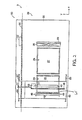
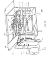
- FIG. 2 is a top schematic view of the three-dimensional printer 3 of FIG. 1 . Shown in more detail are the front powdery area 20 and the rear clean area 50.
- a print gantry 40 is suspended over the top deck 22 by an arm assembly 55 connected to a track 57 and a support rod 23. During operation, the arm moves along the x-axis (slow axis) on the track 57 and the support rod 23 to move the gantry 40.
- the gantry 40 carries a printhead 45, which deposits binder liquid.
- the printhead 45 reciprocates in the y-axis direction along a print track 46.
- the gantry 40 includes at least one ink jet printhead 45, having a plurality of binder jets 47 for depositing a binder liquid.
- the binder jets receive binder solution from a binder conduit 77.
- a spreader roller 48 for dispersing build powder from the feed chamber 24 to the build chamber 26.
- Air can be circulated inside the machine to solve a variety of problems.
- One specific problem is airborne powder, which can contaminate printer mechanical and electronic components and thereby decrease machine reliability. Also, the powder can accumulate inside the top cover of the machine, thereby reducing the operator's ability to monitor machine operation.
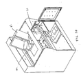
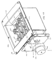
- FIG. 3A is a perspective view of the basic elements for regulating airflow through the three-dimensional printer 3 of FIG. 1 .
- the three-dimensional printer 3 includes a top deck 22 having a plurality of apertures.
- the top deck 22 is mounted to a structural frame. Illustrated along the x-axis (slow axis) are a rectangular feed chamber 24 having a feed piston 25, a rectangular build chamber 26 having a build piston defining a build table 27, and an overflow chute 28.
- seals are fixed to the pistons 25, 27 to slide against the walls of the chambers 24, 26.
- a top cover isolates the printing area from the outside environment.
- FIG. 3A also illustrates elements of a printer designed to facilitate reclaiming spent build material.
- build material that flows into the overflow chute 28 is drawn into a collection bucket 81.
- the collection bucket 81 slides into a mount 82 on the floor of the printer such that the bucket 81 is positioned to receive build material exiting the bottom of chute 28.
- a top plate 83 forms a seal over the bucket 81, and a blower 34, mounted on top plate 83, creates a downward draft through the chute 28.
- a filter 31 is mounted on top plate 83 between the blower 34 and the cavity enclosed by the bucket 81 and the top plate 83. Due to the respective positioning of these elements, overflow build material is collected primarily in the bucket 81 rather than upon the filter 31.
- the build material that falls to the floor of the bucket 81 is more removed from the flow path of the air passing from the chute 28 through the blower 34.
- the bucket 81 can be easily removed to return the build material back to the feed chamber as illustrated in FIG. 3B .
- a lip 84 on the bucket 81 further facilitates pouring.
- one or more optical sensors are positioned to sense when the bucket 81 is full.
- optical sensors can be positioned to sense at a location inside of the bottom end of chute 28.
- the airflow through the overflow chute 28 reduces the amount of airborne powder to enhance machine reliability and user satisfaction.
- a vacuum pump can be connected to the feed chamber 24 and/or the build chamber 26 via conduits. It has been found that drawing air from the build material in through the bottom of the feed chamber 24, while the chamber is being filled, causes the build material to pack densely and uniformly in the feed chamber. This greatly reduces the need for the operator to work the air out of the build material with a trowel during filling, a time consuming process that tends to produce an undesirable cloud of airborne powder.
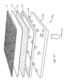
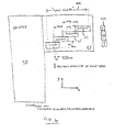
- FIG. 3C illustrates one arrangement of a plenum 240 positionable on the bottom of the feed chamber 24 and build chamber 26.
- the plenum 240 includes a piston plate 242, which serves as a base for the plenum.
- a vacuum pump is attached through a port 244.
- a top plate 246 that provides support for a filter medium 248 and is perforated with holes 250.
- the filter medium 248 maintains a separation between the build material and the vacuum system, which can further include additional in-line filters.
- the holes 250 provide passage for downward airflow and can be arranged for optimum airflow characteristics.
- a plurality of spacers 252 are provided between the piston plate 242 and plate 246 to establish a space for ensuring an even distribution of vacuum in the plenum 240.
- gasket 254 between the piston plate 242 and plate 246 inhibits air leakage around the edges of the plenum 240.
- a mesh 256 is provided above the filter 248 to protect it during setup and cleanup operations.
- the plenum 240 is sandwiched together with screws along the perimeter that extends from the mesh 256 to the piston plate 242.
- a seal can be provided on the perimeter of the plenum 256 to prevent powder loss between the piston and the chamber wall.
- FIG. 3D is a schematic for controlling the airflow through the feed chamber 24 and/or build chamber 26.
- a vacuum pump 258 is coupled to the feed chamber plenum 241 and build chamber plenum 243 tor creating an airflow through either or both plenums.
- vacuum pump 258 is capable of pulling a vacuum level of about 10 inches of mercury with a flow rate of 11 ⁇ 2 to 2 in 3 of air per minute.
- a first valve 260 is shown disposed between the vacuum pump 258 and the feed plenum 241 and build chamber plenum 243. The first valve 260 allows selective directioning of the airflow through either the feed plenum or the build plenum.
- a switch 262 is configured to be activate by the user, for example, to direct the valve 260 such that all the airflow is directed through the feed plenum 242 while the user is filling the feed chamber 24.
- the user can activate the switch 262, which can be a foot pedal, to direct all the airflow through the build plenum 243.
- a flow meter 261 can be disposed between the valve 260 and/or vacuum pump 258 to measure the air volume flow rate between this valve 260 and the vacuum pump.
- a valve 264 which can be a three-way valve, can be further provided between the valve 260 and the build chamber plenum 243.
- the valve 264 is coupled to and controlled by software instructions 265. More particularly, the software instructions 265 control the valve 264 to selectively allow airflow through the build chamber plenum 243 during the fabrication process by controlling a solid state relay 266 to make contact between power lines 268. For example, airflow can be allowed through the build chamber plenum 243 during application of the build material but turned off during printing of the liquid binder material.
- In-line gauges 270 can be provided adjacent to the feed and/or build plenums to measure the level of vacuum at these locations.
- In-line filters 272 can be further provided to filter any build material or debris that may pass through or around plenums 241 and 243.
- an adjustable regulator 274 can be provided between the build chamber plenum 243 and the valve 264 for controlling the flow of air through the build chamber plenum 243.
- a gauge 276 can be further coupled to the regulator 274 for measuring the level of vacuum through the regulator.
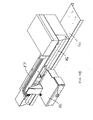
- FIG. 4A Elements of a three-dimensional printer that is particularly suited for highspeed printing in both mono-color and multi-color modes are illustrated in FIG. 4A .
- a carriage 85 is mounted for reciprocation on the gantry 40.
- the carriage 85 can reciprocate along the y-axis (fast axis) via a rail 86.
- the carriage 85, with its cover closed, and the gantry 40 are illustrated with the binder conduits 87 in FIG. 4B .
- FIG. 4C The carriage 85 with its cover open is illustrated in FIG. 4C .
- substantially-identical printheads 45 are mounted within the carriage 85.
- Each of the printheads 45 are coupled with one of the conduits 87, which in turn are coupled with external binder liquid sources.
- one printhead is coupled with a source providing a binder liquid including cyan colorant;
- a second printhead is coupled with a source providing a binder liquid including magenta colorant;
- a third printhead is coupled with a source providing a binder liquid including yellow colorant;
- the fourth printhead is coupled with a source providing a clear (or white) binder liquid.
- a fifth printhead coupled with a source supplying a binder liquid including black colorant and offset from the other printheads along the x-axis can further be provided within the carriage 85.
- the various colorants can be pre-mixed with binder liquid and stored in respective fluid sources, or the colorants can be separately stored and mixed with binder liquid in the machine, for example, at the printhead before printing.
- FIGS. 5A-5D are schematics illustrating a process for handling the build powder. Illustrated are the feed chamber 24, the build chamber 26 and the overflow chute 28 depressed in the top deck 22. A supply of build powder 60 is supported in the feed chamber 24 by the movable feed piston 25, and the build table 27 is shown within the build chamber 26. As known in the art, the feed piston 25 moves incrementally upward (in the z+ direction) during operation, while the build table 27 moves incrementally downward (in the z- direction). An airflow down through the overflow chute 28 is created by the blower 34 ( FIG. 3A ).
- the floor 25 of the feed reservoir chamber 24 has been positioned such that a sufficient quantity 62 of build material 60 for one build layer protrudes above the feed chamber 24.
- the build table 27 has been positioned to a specific depth to receive a first layer of build material. In one arrangement, the build table 27 is incrementally lowered to create a plurality of successive build layers, each about 3-9 mils thick.
- the roller is rotated counter to its forward motion to push the quantity of build material 62 forward toward the build chamber 26.
- the roller 48 continues across the build chamber 26 to deposit a finite layer of build material 64 onto the build table 27.
- an excess amount of build material 60 is provided by and removed from the feed reservoir 24. This excess build material 66 is dumped by the roller 48 into the overflow chute 28 where gravity and air flow carry the particles to the collection bucket 81 ( FIG. 3A ).
- a crusted layer is typically generated on the bottom of the gantry as a result of airborne powder mixing with airborne binder material at the gantry surface.
- This layer tends to become thick over time and drag on the powder bed, causing indentations or grooves on the top layer of the powder bed and leading to flaws in the final part.
- Small brushes, loop material (e.g., Velcro® fastener material), or another abrasive 29 can be placed on the top deck 22 to scrape excess debris from the bottom of the gantry. This debris may be drawn down into the overflow chute 28.
- the 2-D cross-section of that layer is printed.
- the printing occurs during successive passes of the printhead in the y-direction during a pass of the gantry in the negative x-direction.
- Other printing methods can be used instead, as described in detail below.
- the plows 49 tend to contain the wave of powder 65. This prevents build material from spilling over onto the top deck 22 and forming a ridge, which is undesirable from the standpoint of machine reliability and user satisfaction.
- the plows 49 form a seal against the ends of rotating and translating spreader roller 48 and against the top of the top deck 22. Springs can be utilized to generate an inward force on the plows 49 toward each other, causing the plows 49 to form a tight seal with the spreader roller 48. Springs also generate a downward force on the plows 49 to form a seal with the top of the top deck 22.
- the plows 49 can be fabricated from an oil-filled plastic material to reduce the friction between the bottom of the plows 49 and the top of the top deck 22 during powder spreading.
- the oil-filled material also forms a barrier which prevents powder from sticking to the bottom of the plows 49.
- the oil-filled material may also provide a self-replenishing release layer on the bearing surface of top deck 22.
- the overflow chute 28 can be wider than the feed reservoir 24 and build chamber 26 openings to capture this excess powder.
- the impact of the binder hitting the powder layer during printing causes powder to fly up and hit the bottom of the printhead. Because the printhead may be wet with binder, the powder may then harden and form a crust on the bottom of the printhead, or it could possibly eventually get inside the jets, thereby clogging the outlet of the jets. In addition, excess binder may occasionally form droplets that rest on the bottom of the printhead and remain there as a result of surface tension. This effect can also cause blocking of the outlet of the jets or deflection of the jets. When jets are blocked or deflected, the binder is not deposited where desired, thereby causing faults in the final part. Therefore, a method is desired to clean the powder or binder from the bottom of the printhead to keep the jet outlets open.
- a depression 90 is formed in the top deck 22 which includes at least one squeegee or wiper element movable with respect to the structural frame and top deck 22 for cleaning the print jets.
- This depression 90 can be formed anywhere on the deck such that the squeegee(s) will be in the path of the print jets.
- the depression 90 is formed away from the overflow chute 28 opposite the build feed reservoir 24 and build chamber 26.
- a cleaning assembly 200 which is mounted within the depression 90, includes squeegees 209 mounted on a support element 204, which moves up or down by motor 206.
- a motor 206 rotates a gear 208, which intermeshes with and drives a gear 210.
- the gears 208, 210 are connected to and rotate shafts 212 (only one shaft shown in FIG. 4E ), which rotate cams 214 to raise and lower an intermediate element 216, which is attached to a support element 204.
- a PC board 220 supports sensors 222, which sense the position of squeegees (up or down) by sensing the position of a wheel 224 attached to one of the shafts 212.
- the wheel 224 includes embedded magnets that are sensed by the sensors 222 to determine whether the squeegees are up or down.
- the cleaning assembly 200 can include a flange 218 for securing the assembly within the depression 90.
- the motor 206 raises the support element 204 upward such that the squeegees 209 extend above the deck 22 to scrape against and clean the printhead faces. The squeegees 209 are then retracted into the depression 90.
- the cleaning squeegee can be fixed in place, such as on the top deck 22.
- the cleaning squeegee can then be positioned so that the printhead periodically passes over the squeegee, such as every printing pass. Accumulated powder and binder can then be scraped off the printhead by the squeegee.
- the squeegee can then be cleaned by a cleaning agent from, for example, a proximally-located cleaning jet or from the printhead jets itself. Suitable drainage solutions can also be incorporated into the printer to carry away the waste material.
- a fixed squeegee is less mechanically complex, it may not be suitable for all embodiments.
- retractable squeegees are protected in the depression 90 when not in use.
- a nozzle or nozzles 226 containing a cleaning agent for example, clear binder, can be directed at the squeegees for cleaning the same. With the nozzles 226 positioned below the deck 22, the spray of the cleaning agent is relatively contained within the cavity 90.
- the cleaning agent can include a fluid that has lubricating characteristics. That is, the cleaning agent deposits a film on the squeegees 209 that is transferred to the print jets such that the build material is less inclined to stick to the print jets.
- the cleaning agent includes water mixed with about 5-20% polyethylene glycol.
- a support element 204 also carriers printhead cap assemblies 202 that can be used to protect the printheads when they are not in use.
- the build time has two primary components: the spreading of the powder and the depositing of the binder liquid.
- the rate of spreading powder is limited by several factors, including the need to maintain a smooth top layer and to minimize airborne powder. Therefore, one method of increasing the build rate is to increase the rate of binder deposition.
- a method to increase the speed of depositing binder includes using multiple printheads.
- FIG. 6 is a schematic of an apparatus employing multiple printheads. This arrangement maximizes print speed in monochrome print mode because all printheads 45 can print simultaneously, thereby completely covering a total width Wt in the x direction equal to the width of each jet array Wj multiplied by the number of printheads. After printing this total width Wt through the entire y direction, the gantry then advances by a distance equal to the total width Wt in the x-direction. Then the printheads 45 print again covering the total width Wt through the entire y direction again.
- This arrangement is also efficient for color printing.
- the gantry advances by just the width of one jet array Wj, so that each printhead, with its unique color, has the opportunity to pass over each region of the powder.
- the printheads 45 are not placed directly next to each other is that the width of each printhead Wp is greater than the width of the jet array Wj, so if they were placed next to each other there would be a vertical stripe that would not be printed. Therefore, in order to be able to print on every region, the printheads 45 are offset in the y axis by an offset distance Wy to accommodate the physical constraints of the printheads 45.
- the printheads 45 are also offset by an offset Wx along the x-axis.
- the printheads 45 are aligned such that there is a small overlap Wo of printing coverage in the x axis; that is, two adjacent printheads 45 could print on the same x position simultaneously. This allows for less accuracy during the design and manufacturing process because the printheads 45 can be calibrated after the machine is assembled. Then one of the overlapping printheads 45 can be instructed not to print the few pixels that overlap with those of the another printhead.
- the cleaning elements 209 are aligned along the y-axis, and spaced so that each cleaning element registers with a respective printhead.
- the printheads 45 can be arranged in a row along the fast y-axis to form a continuous sequence of binder jets. Such an arrangement would not require movement or reciprocation of the printheads 45 along the fast y-axis during binder deposition.
- a variation of this arrangement can include a partial row of printheads along the fast y-axis. Binder deposition would first occur during passage of the printheads along the slow x-axis (in the x + direction). Once that pass is complete, the printheads can be indexed along the fast y-axis and binder deposited on the return pass (in the x- direction). This process can be repeated until full coverage is achieved.
- jets in the printhead may not be firing or the firing may be flickered as a result of a head that is manufactured poorly or one that has become contaminated by powder.
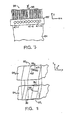
- FIG. 7 is a schematic of a printhead having a faulty binder jet.
- the printhead 45f is one of a plurality of printheads which print along the y-axis as the gantry 40 ( FIG. 2 ) moves. If a particular jet 47-6 of a printhead 45f does not fire, then a stripe 96 may appear in the y direction on the particular layer of powder that is being printed 64. This creates an undesired discontinuity in the printed area 95. The problem is that this vertical strip of unbound powder 96 is at the same x location, xf, on each layer, thereby causing a plane of delamination, once the part is complete.
- FIG. 8 is a schematic of a method of printing two layers with a faulty binder jet, in which a shingling technique is used to cause the unbound vertical stripes 96-1, 96-2 to be placed in different x locations on each layer 64-1, 64-2, thereby distributing the areas of weakness throughout the entire part, instead of concentrating them into one plane. Therefore, the faulty jet 47-6 is located at a different x location on each pass relative to every adjacent layer. Shingling with a multiple cartridge system can be accomplished by a slight offset x o of the cartridge 45 along the x-axis prior to laying each new layer of binder.
- part strength can be improved.
- high binder volume deposition has the disadvantages of decreasing the build rate and resulting in part distortion.
- One method to improve the part strength and minimize part distortion without a large increase in build rate is to increase the volume of binder as it is applied on the perimeter of each layer, thereby forming a hard shell around the part. This can be achieved by increasing the flow rate when the binder is being applied to the perimeter, by applying the binder twice to the perimeter of the part, or by adjusting the binder saturation.
- This method has the added advantage that it can control distortion of the parts' interior regions.
- a 180 x 180 pixel area would be scaled up to 180 x 270 pixels, and the fast axis velocity would be reduced from 90 cm/sec to 60 cm/sec.
- the strength of the part can be optimized.
- a part can be formed having a strong shell and a truss or an egg-crate structure in the parts' interior region. The remainder of the interior can remain as loose powder.
- Color ink jet printheads can be incorporated in the printer, thereby providing the capability of printing a wide range of colors or ink. Because the system uses these heads to deposit liquid binder, they can be used to deposit a color binder as the material that causes the porous material to bind. In particular, the powder material is white or colorless and can absorb the ink to color the powder.
- a certain quantity of liquid binder can be deposited into a given volume of powder to produce a well-formed part. Too much binder can result in the binder migrating beyond the intended area of the part. This effect is customarily called “bleeping.” Quantities of binder below this certain amount, however, produce progressively weaker parts. It is desirable to use a sufficiently optimal quantity of binder independent of amount of color.
- One method for producing parts with controlled variations in color is as follows.
- a minimum amount of saturation is determined for printing on the edges of each layer (which are, in the end, the surface of the part). Adequate colorant is added to each colored binder such that at this minimum saturation of printing the surface of the final part will be the pure primary color. There are three printheads that print binder colored with each of the three primary colors. There is a fourth head that prints clear binder.
- the computer software Before printing each layer, the computer software performs an algorithm that first calculates the amount of colored binder that needs to be printed in each spot by each printhead in order to achieve the desired color. Then the software performs an algorithm which determines the optimum saturation (e.g., increased saturation on the perimeter of each layer, with a truss structure on the interior, as discussed above) for each spot. The software then subtracts the total amount of binder that was already printed by all three color printheads, and then the remaining amount of binder, which is clear and therefore has no impact on the color, is applied by the fourth printhead. Thus each spot receives the correct amount of each color and the correct amount of binder.
- the optimum saturation e.g., increased saturation on the perimeter of each layer, with a truss structure on the interior, as discussed above
- the printer prints onto white powder and could have two sets of jet arrays.
- One set of jet arrays deposits a black binder
- the other set of jet arrays deposits a clear binder which appears white, since the powder is white.
- the two types of binder are deposited in a ratio to produce the shade of gray, white, or black desired in that region of part. All regions of the part thus receive a sufficient total amount of binder needed to produce a strong part.
- Such a technique implies printheads that can produce controlled size droplets.
- an ink jet printhead could be chosen to produce droplets of a controlled range of sizes, most current printheads work best if they are used to produce droplets of one size only. Thus, if the droplets are distributed uniformly across the layer, each location of the part's cross section is hit by either a black droplet or a clear droplet. For dithering or halftoning, these droplets can be distributed in such a manner that when viewed from a sufficient distance a gray is perceived, but when magnified, it is seen as a pattern of dots.
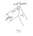
- an algorithm must be applied to the printed area that forms the color band on the perimeter of each layer (see FIG. 9 ).
- the simplest algorithm is a simple miter. It should be noted that the parts are not completely opaque, therefore the color that is perceived by the viewer of a part is dependent on the depth into the surface of the part into which the color is printed. Therefore, a wide color band will produce stronger colors than a narrower color band. The method of forming this band is not according to the present invention.
- the color of the band relating to one surface can impact the perceived color from an adjacent surface. For example, in FIG. 9 , if Color 2 is black and Color 1 is white, then the viewer may see the black through the surface that was supposed to be white. To minimize this effect, the respective color bands at adjacent surfaces can be beveled to leave a white or uncolored strip extendin from an edge of the object into the object, in accordance with the present invention.
- a band 92 of a first color meets a band 94 of a second color at a corner.
- Tapered area 96 is formed of a clear binder such that bands 92, 94 are perceived as their true color and the perception of each color is impacted less by the presence of the other color in the "background.”
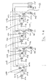
- FIG. 11A is a schematic block diagram of a system of printheads 145A-145D fed by pressure-controlled conduits 87A-145D.
- the binder supply system includes a plurality of printheads 145A, 145B, 145C, 145D coupled to a plurality of binder supply reservoirs 175, 112, 114, 116 and a waste receptacle 155.
- a yellow binder supply reservoir 112 is coupled to a yellow-designated printhead 145B
- a magenta binder supply reservoir 114 is coupled to a magenta-designated printhead 145C
- a cyan binder supply reservoir 116 is coupled to a cyan-designated printhead 145D.
- the clear binder supply reservoir 175 is coupled to a clear-designated printhead 145A and also to each of the color-designated printheads 145B, 145C, 145D. All printheads 145A-145D are also coupled to the waste receptacle 155. Further details are described below.
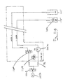
- FIG. 11B shows the binder liquid supply apparatus for printhead 145A of FIG. 11A , which is designated to print clear (colorless) binder liquid.
- valve 122A is open to allow flow, and valve 128A is closed to block flow.
- a pump 185A draws clear binder liquid from its reservoir 175 through a filter 118A and supplies the liquid under pressure to printhead 145A through conduit 87A and valve 122A.
- a pressure switch 121A is configured to inhibit the action of the pump 185A whenever a preset pressure level (for example, 3 psi) has been reached. By this mechanism, the pressure of the clear binder liquid at the printhead 145A is maintained at approximately the preset pressure level.
- a preset pressure level for example, 3 psi
- valve 128A is opened to allow flow, allowing binder liquid from the reservoir 175 to be circulated through the apparatus and returned to the waste receptacle 155.
- This configuration for example allows the binder liquid in the apparatus to be refreshed periodically when the printer is idle for long intervals.
- the valve 122A is closed to block flow, for example to prevent the binder liquid in the printhead from draining back into the clear supply reservoir 175 when the printer is inactive.
- FIG. 11C shows the binder liquid supply apparatus for a printhead 145B of FIG. 11A , which is designated to print yellow binder liquid.
- This apparatus differs from the clear binder supply apparatus shown m FIG. 11B by the addition of a valve 120B, which is configured to allow a pump 185B to draw binder liquid as required either from the clear supply reservoir 175 or from a yellow liquid reservoir 112.
- the other printheads 145C, 145D in a manner identical to that described for the yellow printhead 145B, can be selectively supplied with either clear binder liquid or with colored binder liquid from the associated colored liquid reservoirs 114, 116.
- valves 120B-120D can all be configured to supply clear binder to their respective printheads, for example to print a monochrome part at a high build rate.
- each head can be supplied with a different color to allow a colored part to be printed.
- the valves 128B-128D can be opened to facilitate flushing of undesired binder liquid from the color head supply apparatus into the waste receptacle 155.
Claims (6)
- Ein Verfahren zum Drucken eines dreidimensionalen Objekts, welches darin besteht, dass- eine erste gefärbte Bindemittelflüssigkeit auf ein Aufbaumaterialbett aufgetragen wird zur Herstellung eines ersten farbigen Streifens (92) entlang einer ersten Kante,- eine zweite gefärbte Bindemittelflüssigkeit auf ein Aufbaumaterialbett aufgetragen wird zur Herstellung eines zweiten farbigen Streifens (94) entlang einer zweiten Kante, wobei die erste Kante und die zweite Kante eine Schnittstelle bilden, und- farblose Bindemittelflüssigkeit auf das Materialbett zwischen dem ersten Streifen und dem zweiten Streifen aufgetragen wird zur Herstellung eines farblosen Streifens (96), wobei sich der farblose Streifen von der Ecke aus erstreckt, an der sich die farbigen Streifen berühren und von besagter Ecke aus in das Objekt erstrecken, und wobei der farblose Streifen konisch geformt ist.
- Verfahren nach Anspruch 1, welches desweiteren darin besteht, dass mit einer höheren Konzentration der ersten gefärbten Bindemittelflüssigkeit und einer höheren Konzentration der zweiten gefärbten Bindemittelflüssigkeit an den konischen Abschnitten des farblosen Streifens gedruckt wird.
- Verfahren nach Anspruch 1, wobei sich der erste farbige Streifen (92) von einer ersten Oberfläche des dreidimensionalen Objekts in das Objekt hinein erstreckt, und der Streifen an der Kante konisch geformt ist, an der die erste Oberfläche eine benachbarte Oberfläche berührt, und sich der zweite farbige Streifen (94) von der benachbarten Oberfläche in das Objekt hinein erstreckt, und der Streifen an der Kante konisch geformt ist, an der die benachbarte Oberfläche die erste Oberfläche berührt, so dass ein farbloser Abschnitt (96) zwischen den farbigen Streifen verbleibt.
- Verfahren nach Anspruch 1, welches desweiteren das Auftragen der Substanzen beinhaltet, um höhere Konzentrationen an Farbstoff in den konischen Abschnitten der farbigen Streifen zu erzielen als in den übrigen Abschnitten der farbigen Streifen.
- Ein rechnerlesbares Medium für die Durchführung des Verfahrens nach Anspruch 1 zur Speicherung von Software-Anweisungen, die Befehle zur Steuerung mindestens eines Druckkopfes generieren, wenn dieser eine Substanz, einschließlich eines Farbstoffs, auf ein Aufbaumaterialbett zur Erzeugung eines mehrfarbigen dreidimensionalen Objekts druckt, wobei die Software-Anweisungen Befehle zum Drucken der Substanz in Streifen enthalten, die sich von Oberflächen des dreidimensionalen Objekts in das Objekt hinein erstrecken, und die farbigen Streifen an den Kanten des dreidimensionalen Objekts konisch geformt sind, sodass ein farbloser Abschnitt zwischen benachbarten farbigen Streifen verbleibt.
- Rechnerlesbares Medium nach Anspruch 5, wobei die Software-Anweisungen desweiteren Befehle generieren, dahingehend, dass mit einer höheren Konzentration an Farbstoff in den konischen Abschnitten der Streifen gedruckt wird.
Priority Applications (1)
| Application Number | Priority Date | Filing Date | Title |
|---|---|---|---|
| EP10182753.3A EP2261009B1 (de) | 2001-05-08 | 2002-05-08 | Verfahren und Vorrichtung zur Herstellung eines dreidimensionalen Prototyps |
Applications Claiming Priority (3)
| Application Number | Priority Date | Filing Date | Title |
|---|---|---|---|
| US851502 | 2001-05-08 | ||
| US09/851,502 US6989115B2 (en) | 1996-12-20 | 2001-05-08 | Method and apparatus for prototyping a three-dimensional object |
| PCT/US2002/014591 WO2003016067A2 (en) | 2001-05-08 | 2002-05-08 | Method and apparatus for prototyping a three-dimensional object |
Related Child Applications (2)
| Application Number | Title | Priority Date | Filing Date |
|---|---|---|---|
| EP10182753.3A Division EP2261009B1 (de) | 2001-05-08 | 2002-05-08 | Verfahren und Vorrichtung zur Herstellung eines dreidimensionalen Prototyps |
| EP10182753.3 Division-Into | 2010-09-29 |
Publications (2)
| Publication Number | Publication Date |
|---|---|
| EP1385704A2 EP1385704A2 (de) | 2004-02-04 |
| EP1385704B1 true EP1385704B1 (de) | 2011-11-16 |
Family
ID=25310926
Family Applications (2)
| Application Number | Title | Priority Date | Filing Date |
|---|---|---|---|
| EP02789141A Expired - Lifetime EP1385704B1 (de) | 2001-05-08 | 2002-05-08 | Verfahren und computerlesbares medium zur generativen herstellung eines dreidimensionalen prototyps |
| EP10182753.3A Expired - Lifetime EP2261009B1 (de) | 2001-05-08 | 2002-05-08 | Verfahren und Vorrichtung zur Herstellung eines dreidimensionalen Prototyps |
Family Applications After (1)
| Application Number | Title | Priority Date | Filing Date |
|---|---|---|---|
| EP10182753.3A Expired - Lifetime EP2261009B1 (de) | 2001-05-08 | 2002-05-08 | Verfahren und Vorrichtung zur Herstellung eines dreidimensionalen Prototyps |
Country Status (7)
| Country | Link |
|---|---|
| US (1) | US6989115B2 (de) |
| EP (2) | EP1385704B1 (de) |
| JP (2) | JP4491230B2 (de) |
| AT (1) | ATE533610T1 (de) |
| CA (1) | CA2447573C (de) |
| HK (1) | HK1059761A1 (de) |
| WO (1) | WO2003016067A2 (de) |
Cited By (3)
| Publication number | Priority date | Publication date | Assignee | Title |
|---|---|---|---|---|
| CN105835359A (zh) * | 2015-01-16 | 2016-08-10 | 研能科技股份有限公司 | 快速成型装置的打印模块 |
| CN106032061A (zh) * | 2015-03-16 | 2016-10-19 | 研能科技股份有限公司 | 立体成型装置 |
| TWI632049B (zh) * | 2014-08-19 | 2018-08-11 | 英華達股份有限公司 | 結合材料噴頭和顏料噴頭的3d列印方法及系統 |
Families Citing this family (258)
| Publication number | Priority date | Publication date | Assignee | Title |
|---|---|---|---|---|
| US6007318A (en) * | 1996-12-20 | 1999-12-28 | Z Corporation | Method and apparatus for prototyping a three-dimensional object |
| US7037382B2 (en) * | 1996-12-20 | 2006-05-02 | Z Corporation | Three-dimensional printer |
| US7534263B2 (en) | 2001-05-25 | 2009-05-19 | Conformis, Inc. | Surgical tools facilitating increased accuracy, speed and simplicity in performing joint arthroplasty |
| US8882847B2 (en) | 2001-05-25 | 2014-11-11 | Conformis, Inc. | Patient selectable knee joint arthroplasty devices |
| US8083745B2 (en) | 2001-05-25 | 2011-12-27 | Conformis, Inc. | Surgical tools for arthroplasty |
| US8735773B2 (en) | 2007-02-14 | 2014-05-27 | Conformis, Inc. | Implant device and method for manufacture |
| US7468075B2 (en) | 2001-05-25 | 2008-12-23 | Conformis, Inc. | Methods and compositions for articular repair |
| US8545569B2 (en) | 2001-05-25 | 2013-10-01 | Conformis, Inc. | Patient selectable knee arthroplasty devices |
| WO2001034371A2 (en) * | 1999-11-05 | 2001-05-17 | Z Corporation | Material systems and methods of three-dimensional printing |
| US20010050031A1 (en) * | 2000-04-14 | 2001-12-13 | Z Corporation | Compositions for three-dimensional printing of solid objects |
| JP4785333B2 (ja) | 2000-09-25 | 2011-10-05 | フォクセルジェット テクノロジー ゲーエムベーハー | 堆積法によるパーツ作製方法 |
| ATE504264T1 (de) | 2001-05-25 | 2011-04-15 | Conformis Inc | Verfahren und zusammensetzungen zur reparatur der oberfläche von gelenken |
| US8439926B2 (en) | 2001-05-25 | 2013-05-14 | Conformis, Inc. | Patient selectable joint arthroplasty devices and surgical tools |
| DE10216013B4 (de) | 2002-04-11 | 2006-12-28 | Generis Gmbh | Verfahren und Vorrichtung zum Auftragen von Fluiden |
| WO2003096308A1 (en) * | 2002-05-10 | 2003-11-20 | Nagoya Industrial Science Research Institute | Three-dimensional model |
| US7087109B2 (en) * | 2002-09-25 | 2006-08-08 | Z Corporation | Three dimensional printing material system and method |
| US20040080078A1 (en) * | 2002-10-25 | 2004-04-29 | Collins David C. | Methods and systems for producing a desired apparent coloring in an object produced through rapid prototyping |
| US7589868B2 (en) * | 2002-12-11 | 2009-09-15 | Agfa Graphics Nv | Method and apparatus for creating 3D-prints and a 3-D printing system |
| CN103358550B (zh) * | 2003-05-01 | 2016-03-30 | 斯特拉特西斯有限公司 | 快速成型装置 |
| EP1475220A3 (de) * | 2003-05-09 | 2009-07-08 | FUJIFILM Corporation | Verfahren zur Herstellung eines dreidimensionalen Modells und dreidimensionales Modell |
| WO2004106041A2 (en) * | 2003-05-23 | 2004-12-09 | Z Corporation | Apparatus and methods for 3d printing |
| US7807077B2 (en) | 2003-06-16 | 2010-10-05 | Voxeljet Technology Gmbh | Methods and systems for the manufacture of layered three-dimensional forms |
| US7141617B2 (en) * | 2003-06-17 | 2006-11-28 | The Board Of Trustees Of The University Of Illinois | Directed assembly of three-dimensional structures with micron-scale features |
| US7645403B2 (en) | 2003-06-24 | 2010-01-12 | Hewlett-Packard Development Company, L.P. | Method of improving color quality in an object produced by solid freeform fabrication |
| US20050087897A1 (en) * | 2003-10-23 | 2005-04-28 | Nielsen Jeffrey A. | Systems and methods for reducing waste in solid freeform fabrication |
| DE102004008168B4 (de) | 2004-02-19 | 2015-12-10 | Voxeljet Ag | Verfahren und Vorrichtung zum Auftragen von Fluiden und Verwendung der Vorrichtung |
| WO2005097476A2 (en) * | 2004-04-02 | 2005-10-20 | Z Corporation | Methods and apparatus for 3d printing |
| DE102004025374A1 (de) * | 2004-05-24 | 2006-02-09 | Technische Universität Berlin | Verfahren und Vorrichtung zum Herstellen eines dreidimensionalen Artikels |
| WO2006045178A1 (en) * | 2004-10-26 | 2006-05-04 | 2089275 Ontario Ltd. | Method for the automated production of three-dimensional objects and textured substrates from two-dimensional or three-dimensional objects |
| US7824001B2 (en) * | 2004-09-21 | 2010-11-02 | Z Corporation | Apparatus and methods for servicing 3D printers |
| US7387359B2 (en) * | 2004-09-21 | 2008-06-17 | Z Corporation | Apparatus and methods for servicing 3D printers |
| US20060159869A1 (en) * | 2005-01-14 | 2006-07-20 | Laura Kramer | Reactive materials systems and methods for solid freeform fabrication of three-dimensional objects |
| US20060214335A1 (en) * | 2005-03-09 | 2006-09-28 | 3D Systems, Inc. | Laser sintering powder recycle system |
| US7357629B2 (en) * | 2005-03-23 | 2008-04-15 | 3D Systems, Inc. | Apparatus and method for aligning a removable build chamber within a process chamber |
| CA2623834A1 (en) | 2005-09-30 | 2007-04-12 | Conformis, Inc. | Joint arthroplasty devices |
| US7520740B2 (en) * | 2005-09-30 | 2009-04-21 | 3D Systems, Inc. | Rapid prototyping and manufacturing system and method |
| US20070126157A1 (en) * | 2005-12-02 | 2007-06-07 | Z Corporation | Apparatus and methods for removing printed articles from a 3-D printer |
| CN105030296A (zh) | 2006-02-06 | 2015-11-11 | 康复米斯公司 | 患者可选择的关节成形术装置和手术器具 |
| US8623026B2 (en) | 2006-02-06 | 2014-01-07 | Conformis, Inc. | Patient selectable joint arthroplasty devices and surgical tools incorporating anatomical relief |
| EP2001656B1 (de) * | 2006-04-06 | 2014-10-15 | 3D Systems Incorporated | Set zur herstellung dreidimensionaler objekte durch verwendung elektromagnetischer strahlung |
| US8105517B2 (en) * | 2006-04-21 | 2012-01-31 | Next21 K.K. | Figure-forming composition, method for forming three-dimensional figures and three-dimensional structures by using the same |
| US7832456B2 (en) * | 2006-04-28 | 2010-11-16 | Halliburton Energy Services, Inc. | Molds and methods of forming molds associated with manufacture of rotary drill bits and other downhole tools |
| CN101495294B (zh) * | 2006-05-26 | 2013-03-13 | 3D系统公司 | 用于处理三维打印机中材料的装置和方法 |
| DE102006030350A1 (de) | 2006-06-30 | 2008-01-03 | Voxeljet Technology Gmbh | Verfahren zum Aufbauen eines Schichtenkörpers |
| DE102006038858A1 (de) | 2006-08-20 | 2008-02-21 | Voxeljet Technology Gmbh | Selbstaushärtendes Material und Verfahren zum schichtweisen Aufbau von Modellen |
| EP2055268A4 (de) | 2006-08-21 | 2012-05-30 | Next21 Kk | Knochenmodell, knochenfüller und verfahren zur herstellung des knochenfüllers |
| JP5405119B2 (ja) | 2006-11-11 | 2014-02-05 | 株式会社ネクスト21 | 骨補填剤,放出制御担体,及びそれらの製造方法 |
| EP2664442B1 (de) * | 2006-12-08 | 2018-02-14 | 3D Systems Incorporated | Dreidimensionales Druckmaterialsystem |
| EP2097247B1 (de) * | 2006-12-21 | 2016-03-09 | Agfa Graphics NV | 3d-tintenstrahldruckverfahren |
| JP5129267B2 (ja) * | 2007-01-10 | 2013-01-30 | スリーディー システムズ インコーポレーテッド | 改良された色、物品性能及び使用の容易さ、を持つ3次元印刷材料システム |
| US20080170112A1 (en) * | 2007-01-17 | 2008-07-17 | Hull Charles W | Build pad, solid image build, and method for building build supports |
| EP2114312B1 (de) | 2007-02-14 | 2014-01-08 | ConforMIS, Inc. | Herstellungsverfahren für ein implantat |
| US7968626B2 (en) | 2007-02-22 | 2011-06-28 | Z Corporation | Three dimensional printing material system and method using plasticizer-assisted sintering |
| US8219234B2 (en) | 2007-03-07 | 2012-07-10 | Objet Geometries Ltd. | Rapid production apparatus with production orientation determination |
| US20080309665A1 (en) * | 2007-06-13 | 2008-12-18 | 3D Systems, Inc., A California Corporation | Distributed rapid prototyping |
| WO2008157412A2 (en) | 2007-06-13 | 2008-12-24 | Conformis, Inc. | Surgical cutting guide |
| US7744364B2 (en) | 2007-06-21 | 2010-06-29 | Stratasys, Inc. | Extrusion tip cleaning assembly |
| US10226919B2 (en) | 2007-07-18 | 2019-03-12 | Voxeljet Ag | Articles and structures prepared by three-dimensional printing method |
| DE102007033434A1 (de) | 2007-07-18 | 2009-01-22 | Voxeljet Technology Gmbh | Verfahren zum Herstellen dreidimensionaler Bauteile |
| EP2188114B1 (de) | 2007-07-25 | 2018-09-12 | Stratasys Ltd. | Mehrere modelliermaterialien verwendende herstellung einer massiven freiform |
| US7625200B2 (en) * | 2007-07-31 | 2009-12-01 | Stratasys, Inc. | Extrusion head for use in extrusion-based layered deposition modeling |
| US20090091591A1 (en) * | 2007-10-07 | 2009-04-09 | Yohanan Sivan | Printing Systems And Methods For Generating Relief Images |
| DE102007049058A1 (de) | 2007-10-11 | 2009-04-16 | Voxeljet Technology Gmbh | Materialsystem und Verfahren zum Verändern von Eigenschaften eines Kunststoffbauteils |
| DE102007050679A1 (de) | 2007-10-21 | 2009-04-23 | Voxeljet Technology Gmbh | Verfahren und Vorrichtung zum Fördern von Partikelmaterial beim schichtweisen Aufbau von Modellen |
| DE102007050953A1 (de) * | 2007-10-23 | 2009-04-30 | Voxeljet Technology Gmbh | Vorrichtung zum schichtweisen Aufbau von Modellen |
| GB0818493D0 (en) * | 2008-10-09 | 2008-11-19 | Reedhycalog Uk Ltd | Drilling tool |
| DE102008058378A1 (de) | 2008-11-20 | 2010-05-27 | Voxeljet Technology Gmbh | Verfahren zum schichtweisen Aufbau von Kunststoffmodellen |
| US7991498B2 (en) | 2009-02-03 | 2011-08-02 | Objet Geometries Ltd. | Method and system for building painted three-dimensional objects |
| US9017334B2 (en) | 2009-02-24 | 2015-04-28 | Microport Orthopedics Holdings Inc. | Patient specific surgical guide locator and mount |
| US8808303B2 (en) | 2009-02-24 | 2014-08-19 | Microport Orthopedics Holdings Inc. | Orthopedic surgical guide |
| US8808297B2 (en) | 2009-02-24 | 2014-08-19 | Microport Orthopedics Holdings Inc. | Orthopedic surgical guide |
| US8545209B2 (en) * | 2009-03-31 | 2013-10-01 | Microjet Technology Co., Ltd. | Three-dimensional object forming apparatus and method for forming three-dimensional object |
| US8342833B2 (en) * | 2009-03-31 | 2013-01-01 | Microjet Technology Co., Ltd. | Three-dimensional object forming apparatus |
| JP2012523897A (ja) | 2009-04-16 | 2012-10-11 | コンフォーミス・インコーポレイテッド | 靭帯修復のための患者固有の関節置換術の装置 |
| DE102009030113A1 (de) | 2009-06-22 | 2010-12-23 | Voxeljet Technology Gmbh | Verfahren und Vorrichtung zum Zuführen von Fluiden beim schichtweisen Bauen von Modellen |
| JP5543740B2 (ja) * | 2009-08-07 | 2014-07-09 | 株式会社コンピュータシステム研究所 | 立体模型製造方法および立体模型 |
| DE102009056695B4 (de) * | 2009-12-02 | 2012-03-29 | Prometal Rct Gmbh | Druckkopf-Reinigungsvorrichtung |
| DE102010006939A1 (de) | 2010-02-04 | 2011-08-04 | Voxeljet Technology GmbH, 86167 | Vorrichtung zum Herstellen dreidimensionaler Modelle |
| US8222908B2 (en) * | 2010-02-16 | 2012-07-17 | Stratasys, Inc. | Capacitive detector for use in extrusion-based digital manufacturing systems |
| DE102010013732A1 (de) | 2010-03-31 | 2011-10-06 | Voxeljet Technology Gmbh | Vorrichtung zum Herstellen dreidimensionaler Modelle |
| DE102010013733A1 (de) | 2010-03-31 | 2011-10-06 | Voxeljet Technology Gmbh | Vorrichtung zum Herstellen dreidimensionaler Modelle |
| DE102010014969A1 (de) | 2010-04-14 | 2011-10-20 | Voxeljet Technology Gmbh | Vorrichtung zum Herstellen dreidimensionaler Modelle |
| DE102010015451A1 (de) | 2010-04-17 | 2011-10-20 | Voxeljet Technology Gmbh | Verfahren und Vorrichtung zum Herstellen dreidimensionaler Objekte |
| CN201685457U (zh) * | 2010-06-02 | 2010-12-29 | 研能科技股份有限公司 | 立体成型机构 |
| DE102010027071A1 (de) | 2010-07-13 | 2012-01-19 | Voxeljet Technology Gmbh | Vorrichtung zum Herstellen dreidimensionaler Modelle mittels Schichtauftragstechnik |
| WO2012085914A1 (en) | 2010-12-21 | 2012-06-28 | Objet Ltd. | Method and system for reuse of materials in additive manufacturing systems |
| DE102010056346A1 (de) | 2010-12-29 | 2012-07-05 | Technische Universität München | Verfahren zum schichtweisen Aufbau von Modellen |
| DE102011007957A1 (de) | 2011-01-05 | 2012-07-05 | Voxeljet Technology Gmbh | Vorrichtung und Verfahren zum Aufbauen eines Schichtenkörpers mit wenigstens einem das Baufeld begrenzenden und hinsichtlich seiner Lage einstellbaren Körper |
| US8512024B2 (en) | 2011-01-20 | 2013-08-20 | Makerbot Industries, Llc | Multi-extruder |
| DE202011003443U1 (de) | 2011-03-02 | 2011-12-23 | Bego Medical Gmbh | Vorrichtung zur generativen Herstellung dreidimensionaler Bauteile |
| JP5703911B2 (ja) * | 2011-04-01 | 2015-04-22 | セイコーエプソン株式会社 | 造形複合装置 |
| US9207355B2 (en) | 2011-05-26 | 2015-12-08 | Baker Hughes Incorporated | Method for physical modeling of reservoirs |
| DE102011111498A1 (de) | 2011-08-31 | 2013-02-28 | Voxeljet Technology Gmbh | Vorrichtung zum schichtweisen Aufbau von Modellen |
| DE102011082873A1 (de) * | 2011-09-16 | 2013-03-21 | Bayerische Motoren Werke Aktiengesellschaft | Vorrichtung und Schichtbauverfahren zum Herstellen von dreidimensionalen Formteilen |
| US9408686B1 (en) | 2012-01-20 | 2016-08-09 | Conformis, Inc. | Devices, systems and methods for manufacturing orthopedic implants |
| DE102012004213A1 (de) | 2012-03-06 | 2013-09-12 | Voxeljet Technology Gmbh | Verfahren und Vorrichtung zum Herstellen dreidimensionaler Modelle |
| JP5772668B2 (ja) | 2012-03-08 | 2015-09-02 | カシオ計算機株式会社 | 3次元造形方法及び造形物複合体並びに3次元造形装置 |
| US9486226B2 (en) | 2012-04-18 | 2016-11-08 | Conformis, Inc. | Tibial guides, tools, and techniques for resecting the tibial plateau |
| DE102012010272A1 (de) | 2012-05-25 | 2013-11-28 | Voxeljet Technology Gmbh | Verfahren zum Herstellen dreidimensionaler Modelle mit speziellen Bauplattformen und Antriebssystemen |
| US9675471B2 (en) | 2012-06-11 | 2017-06-13 | Conformis, Inc. | Devices, techniques and methods for assessing joint spacing, balancing soft tissues and obtaining desired kinematics for joint implant components |
| DE102012012363A1 (de) | 2012-06-22 | 2013-12-24 | Voxeljet Technology Gmbh | Vorrichtung zum Aufbauen eines Schichtenkörpers mit entlang des Austragbehälters bewegbarem Vorrats- oder Befüllbehälter |
| US8888480B2 (en) | 2012-09-05 | 2014-11-18 | Aprecia Pharmaceuticals Company | Three-dimensional printing system and equipment assembly |
| EP2892708B1 (de) | 2012-09-05 | 2018-10-10 | Aprecia Pharmaceuticals LLC | Dreidimensionales drucksystem und vorrichtungsanordnung |
| US9636229B2 (en) | 2012-09-20 | 2017-05-02 | Conformis, Inc. | Solid freeform fabrication of implant components |
| CN104780872B (zh) | 2012-09-21 | 2017-04-05 | 康复米斯公司 | 使用自由实体制造优化植入物组件的设计和制造的方法和系统 |
| DE102012109262A1 (de) * | 2012-09-28 | 2014-04-03 | Bundesrepublik Deutschland, vertreten durch das Bundesministerium für Wirtschaft und Technologie, dieses vertreten durch den Präsidenten der BAM, Bundesanstalt für Materialforschung und -prüfung | Verfahren zur Stabilisierung eines Pulverbetts mittels Unterdruck für die additive Fertigung |
| DE102012020000A1 (de) | 2012-10-12 | 2014-04-17 | Voxeljet Ag | 3D-Mehrstufenverfahren |
| DE102013004940A1 (de) | 2012-10-15 | 2014-04-17 | Voxeljet Ag | Verfahren und Vorrichtung zum Herstellen von dreidimensionalen Modellen mit temperiertem Druckkopf |
| DE102012022859A1 (de) | 2012-11-25 | 2014-05-28 | Voxeljet Ag | Aufbau eines 3D-Druckgerätes zur Herstellung von Bauteilen |
| DE102013003303A1 (de) * | 2013-02-28 | 2014-08-28 | FluidSolids AG | Verfahren zum Herstellen eines Formteils mit einer wasserlöslichen Gussform sowie Materialsystem zu deren Herstellung |
| WO2014144512A1 (en) | 2013-03-15 | 2014-09-18 | Aprecia Pharmaceuticals Company | Rapid disperse dosage form containing levetiracetam |
| US9643362B2 (en) | 2013-03-15 | 2017-05-09 | Microsoft Technology Licensing, Llc | Full color three-dimensional object fabrication |
| EP3007879B1 (de) * | 2013-06-10 | 2019-02-13 | Renishaw Plc. | Vorrichtung und verfahren für selektive lasererstarrung |
| US11077607B2 (en) * | 2013-10-21 | 2021-08-03 | Made In Space, Inc. | Manufacturing in microgravity and varying external force environments |
| EP2851179B1 (de) * | 2013-09-19 | 2017-11-22 | SDD Holding B.V. | Vorrichtung zum gleichzeitigen Drucken von dreidimensionalen Gegenständen |
| US11292241B2 (en) | 2016-05-25 | 2022-04-05 | Shay C. Colson | 3-D packaging and shipping based on aggregate data |
| US11292622B2 (en) | 2013-10-07 | 2022-04-05 | Shay C. Colson | 3D printed vehicle packaging |
| US11716211B2 (en) | 2016-10-01 | 2023-08-01 | James L. Schmeling | 3D-printed packaging with blockchain integration |
| US10676219B2 (en) | 2016-10-01 | 2020-06-09 | Shay C. Colson | Printing packaging in expanded material |
| US9248611B2 (en) | 2013-10-07 | 2016-02-02 | David A. Divine | 3-D printed packaging |
| US10981680B2 (en) | 2013-10-07 | 2021-04-20 | Shay C. Colson | 3-D printed package customization |
| KR101346704B1 (ko) | 2013-10-18 | 2013-12-31 | 이재식 | 멀티칼라 제품성형이 가능한 3d 프린터 |
| DE102013018182A1 (de) | 2013-10-30 | 2015-04-30 | Voxeljet Ag | Verfahren und Vorrichtung zum Herstellen von dreidimensionalen Modellen mit Bindersystem |
| CN104647754A (zh) | 2013-11-18 | 2015-05-27 | 精工爱普生株式会社 | 三维立体造形物、制造方法和装置及装置控制方法和程序 |
| US9744726B2 (en) * | 2013-11-25 | 2017-08-29 | Xerox Corporation | 3D print manufacturing of packages with personalized labeling technology |
| DE102013018031A1 (de) | 2013-12-02 | 2015-06-03 | Voxeljet Ag | Wechselbehälter mit verfahrbarer Seitenwand |
| JP6264006B2 (ja) | 2013-12-10 | 2018-01-24 | セイコーエプソン株式会社 | 造形方法および造形装置 |
| DE102013020491A1 (de) | 2013-12-11 | 2015-06-11 | Voxeljet Ag | 3D-Infiltrationsverfahren |
| DE102013021091A1 (de) | 2013-12-18 | 2015-06-18 | Voxeljet Ag | 3D-Druckverfahren mit Schnelltrockenschritt |
| EP2886307A1 (de) | 2013-12-20 | 2015-06-24 | Voxeljet AG | Vorrichtung, Spezialpapier und Verfahren zum Herstellen von Formteilen |
| US20160332373A1 (en) * | 2013-12-23 | 2016-11-17 | The Exone Company | Methods and Systems for Three-Dimensional Printing Utilizing Multiple Binder Fluids |
| EP3086921B1 (de) * | 2013-12-23 | 2019-07-31 | The Exone Company | Verfahren und systeme zum dreidimensionalen drucken unter verwendung einer bindemittelflüssigkeit mit ausgestrahlten partikeln |
| JP2015131398A (ja) | 2014-01-09 | 2015-07-23 | セイコーエプソン株式会社 | 三次元造形物の製造方法、三次元造形物製造装置、インクセットおよび三次元造形物 |
| JP6387614B2 (ja) * | 2014-01-09 | 2018-09-12 | セイコーエプソン株式会社 | 三次元造形物の製造方法およびインクセット |
| KR101872628B1 (ko) | 2014-01-16 | 2018-06-28 | 휴렛-팩커드 디벨롭먼트 컴퍼니, 엘.피. | 입체 물체 생성 |
| WO2015108551A1 (en) * | 2014-01-16 | 2015-07-23 | Hewlett-Packard Development Company, L.P. | Generating three-dimensional objects |
| GB2538411B (en) * | 2014-01-16 | 2020-09-16 | Hewlett Packard Development Co Lp | Generating three-dimensional objects |
| JP6570542B2 (ja) | 2014-01-16 | 2019-09-04 | ヒューレット−パッカード デベロップメント カンパニー エル.ピー.Hewlett‐Packard Development Company, L.P. | 三次元物体の生成 |
| US10220564B2 (en) | 2014-01-16 | 2019-03-05 | Hewlett-Packard Development Company, L.P. | Generating three-dimensional objects |
| WO2015111059A1 (en) | 2014-01-26 | 2015-07-30 | Stratasys Ltd. | Coloring of three-dimensional printed objects |
| US9415546B2 (en) | 2014-01-29 | 2016-08-16 | Xerox Corporation | System and method for controlling material drop volume in three dimensional object printing |
| WO2015117054A1 (en) * | 2014-02-02 | 2015-08-06 | Worcester Polytechnic Institute | Method and system for fabricating thermal insulation for retrofit applications |
| US10307970B2 (en) | 2014-02-20 | 2019-06-04 | Made In Space, Inc. | In-situ resource preparation and utilization methods |
| JP2015174427A (ja) * | 2014-03-18 | 2015-10-05 | セイコーエプソン株式会社 | 三次元造形物製造装置、三次元造形物の製造方法および三次元造形物 |
| JPWO2015141782A1 (ja) * | 2014-03-19 | 2017-04-13 | シーメット株式会社 | プリントヘッドユニット、三次元積層造形装置、三次元積層造形方法および造形物 |
| WO2015142546A1 (en) * | 2014-03-21 | 2015-09-24 | Carbon3D, Inc. | Method and apparatus for three-dimensional fabrication with gas injection through carrier |
| JP6289201B2 (ja) * | 2014-03-26 | 2018-03-07 | 株式会社ミマキエンジニアリング | 三次元造形物製造用インク及びその利用 |
| DE102014004692A1 (de) | 2014-03-31 | 2015-10-15 | Voxeljet Ag | Verfahren und Vorrichtung für den 3D-Druck mit klimatisierter Verfahrensführung |
| US9162509B1 (en) * | 2014-03-31 | 2015-10-20 | Xerox Corporation | System for detecting inoperative inkjets in printheads ejecting clear ink using thermal substrates |
| JP6519100B2 (ja) | 2014-04-23 | 2019-05-29 | セイコーエプソン株式会社 | 焼結造形方法、液状結合剤、および焼結造形物 |
| JP6461488B2 (ja) * | 2014-05-21 | 2019-01-30 | 株式会社ミマキエンジニアリング | 三次元構造物を形成する形成装置 |
| DE102014007584A1 (de) | 2014-05-26 | 2015-11-26 | Voxeljet Ag | 3D-Umkehrdruckverfahren und Vorrichtung |
| US10065375B2 (en) | 2014-06-04 | 2018-09-04 | Mitsubishi Hitachi Power Systems, Ltd. | Additive manufacturing system, modeling-data providing apparatus and providing method |
| GB2546016B (en) | 2014-06-20 | 2018-11-28 | Velo3D Inc | Apparatuses, systems and methods for three-dimensional printing |
| TW201609934A (zh) | 2014-07-01 | 2016-03-16 | 精工愛普生股份有限公司 | 三維造形用組合物、三維造形物之製造方法及三維造形物 |
| DE102014109706A1 (de) * | 2014-07-10 | 2016-01-14 | Bundesrepublik Deutschland, Vertreten Durch Den Bundesminister Für Wirtschaft Und Energie, Dieser Vertreten Durch Den Präsidenten Der Bundesanstalt Für Materialforschung Und -Prüfung (Bam) | Aufbau und Verwendung einer geometrisch dicht gepackten Pulverschicht |
| JP2016033959A (ja) * | 2014-07-31 | 2016-03-10 | 株式会社東芝 | 負荷時タップ切換器および負荷時タップ切換器用切換開閉器 |
| JP2016033940A (ja) * | 2014-07-31 | 2016-03-10 | 株式会社東芝 | ガス絶縁変圧器 |
| CN106573294B (zh) | 2014-08-02 | 2021-01-01 | 沃克斯艾捷特股份有限公司 | 方法和具体地用于冷铸造方法的铸造模具 |
| KR102199789B1 (ko) * | 2014-08-07 | 2021-01-08 | 삼성전자주식회사 | 조형물 형성 장치 및 조형물 형성 장치의 제어 방법 |
| CN104260353B (zh) | 2014-09-24 | 2017-01-25 | 英华达(上海)科技有限公司 | 快速成型系统及其方法 |
| JP6397293B2 (ja) * | 2014-09-29 | 2018-09-26 | 株式会社Screenホールディングス | 立体造形装置および立体造形物の製造方法 |
| US10052823B2 (en) | 2014-10-08 | 2018-08-21 | Xerox Corporation | System and method for test pattern formation during three-dimensional object printing |
| US10800153B2 (en) * | 2014-11-20 | 2020-10-13 | Hewlett-Packard Development Company, L.P. | Generating three-dimensional objects |
| JP6421562B2 (ja) * | 2014-11-25 | 2018-11-14 | セイコーエプソン株式会社 | 三次元造形物の製造方法および三次元造形物製造装置 |
| US20160151975A1 (en) | 2014-12-02 | 2016-06-02 | Mimaki Engineering Co., Ltd. | Apparatus for forming three-dimensional object and method for forming three-dimensional object |
| JP6532390B2 (ja) * | 2014-12-02 | 2019-06-19 | 株式会社ミマキエンジニアリング | 立体物造形装置および立体物造形方法 |
| CN105751497A (zh) * | 2014-12-19 | 2016-07-13 | 研能科技股份有限公司 | 页宽喷印的快速成型装置 |
| CN105751496A (zh) * | 2014-12-19 | 2016-07-13 | 研能科技股份有限公司 | 页宽喷印的快速成型装置 |
| CN105751494A (zh) * | 2014-12-19 | 2016-07-13 | 研能科技股份有限公司 | 页宽喷印的快速成型装置 |
| CN105751498A (zh) * | 2014-12-19 | 2016-07-13 | 研能科技股份有限公司 | 页宽喷印的快速成型装置 |
| DE102015006533A1 (de) | 2014-12-22 | 2016-06-23 | Voxeljet Ag | Verfahren und Vorrichtung zum Herstellen von 3D-Formteilen mit Schichtaufbautechnik |
| TWI606914B (zh) * | 2015-01-16 | 2017-12-01 | 研能科技股份有限公司 | 快速成型裝置之列印模組 |
| TWI604943B (zh) * | 2015-01-30 | 2017-11-11 | 研能科技股份有限公司 | 快速成型裝置之列印模組 |
| BR112017016457A2 (pt) * | 2015-01-30 | 2018-06-19 | Hewlett-Packard Development Company, L.P. | fabricação de objetos tridimensionais |
| CN105984147B (zh) * | 2015-02-04 | 2018-11-30 | 三纬国际立体列印科技股份有限公司 | 立体打印装置 |
| JP6450017B2 (ja) * | 2015-03-05 | 2019-01-09 | ヒューレット−パッカード デベロップメント カンパニー エル.ピー.Hewlett‐Packard Development Company, L.P. | 3次元物体の生成 |
| DE102015103726A1 (de) * | 2015-03-13 | 2016-09-15 | Exone Gmbh | 3D-Drucker mit Beschichter und Beschichter-Reinigungsvorrichtung |
| DE102015003372A1 (de) | 2015-03-17 | 2016-09-22 | Voxeljet Ag | Verfahren und Vorrichtung zum Herstellen von 3D-Formteilen mit Doppelrecoater |
| GB201505458D0 (en) | 2015-03-30 | 2015-05-13 | Renishaw Plc | Additive manufacturing apparatus and methods |
| US9286554B1 (en) | 2015-04-01 | 2016-03-15 | Xerox Corporation | System and method for halftone printing in a three-dimensional object printer |
| WO2016186613A1 (en) * | 2015-05-15 | 2016-11-24 | Hewlett-Packard Development Company, L.P. | Coalescing agent concentrations and contone densities for three-dimensional objects |
| DE102015006363A1 (de) | 2015-05-20 | 2016-12-15 | Voxeljet Ag | Phenolharzverfahren |
| WO2017007486A1 (en) * | 2015-07-09 | 2017-01-12 | Hewlett-Packard Development Company, L.P. | Generating three-dimensional objects with target surface roughness |
| US9707785B2 (en) | 2015-07-16 | 2017-07-18 | Xerox Corporation | System and method for analysis of compact printed test patterns |
| JP6582684B2 (ja) | 2015-07-30 | 2019-10-02 | セイコーエプソン株式会社 | 立体物造形装置、立体物造形装置と通信可能な情報処理装置、立体物造形装置の制御方法、立体物造形装置を用いた立体物の生産方法、及び、立体物造形システム |
| JP2017030177A (ja) * | 2015-07-30 | 2017-02-09 | セイコーエプソン株式会社 | 立体物造形装置、立体物造形装置の制御方法、立体物造形装置を用いた立体物の生産方法、立体物造形装置と通信可能な情報処理装置、及び、立体物造形システム |
| CN106427249B (zh) * | 2015-08-12 | 2019-06-07 | 三纬国际立体列印科技股份有限公司 | 粉末式3d打印的打印信息处理方法 |
| BR112018001609A2 (pt) | 2015-08-21 | 2018-09-18 | Aprecia Pharmaceuticals LLC | sistema e montagem de equipamento de impressão tridimensional |
| DE102015011503A1 (de) | 2015-09-09 | 2017-03-09 | Voxeljet Ag | Verfahren zum Auftragen von Fluiden |
| DE102015011790A1 (de) | 2015-09-16 | 2017-03-16 | Voxeljet Ag | Vorrichtung und Verfahren zum Herstellen dreidimensionaler Formteile |
| US10733911B2 (en) | 2015-10-14 | 2020-08-04 | Humanetics Innovative Solutions, Inc. | Three-dimensional ribs and method of three-dimensional printing of ribs for crash test dummy |
| US10395561B2 (en) | 2015-12-07 | 2019-08-27 | Humanetics Innovative Solutions, Inc. | Three-dimensionally printed internal organs for crash test dummy |
| WO2017079091A1 (en) | 2015-11-06 | 2017-05-11 | Velo3D, Inc. | Adept three-dimensional printing |
| US10471697B2 (en) | 2015-11-13 | 2019-11-12 | R3 Printing, Inc. | System and method for on-demand colorization for extrusion-based additive construction |
| US10913259B2 (en) | 2015-11-20 | 2021-02-09 | Ricoh Company, Ltd. | Three-dimensional shaping apparatus and three-dimensional shaping system |
| JP6699287B2 (ja) * | 2015-11-20 | 2020-05-27 | 株式会社リコー | 立体造形装置および立体造形システム |
| DE102015015353A1 (de) * | 2015-12-01 | 2017-06-01 | Voxeljet Ag | Verfahren und Vorrichtung zur Herstellung von dreidimensionalen Bauteilen mittels Überschussmengensensor |
| CN108698126A (zh) | 2015-12-10 | 2018-10-23 | 维洛3D公司 | 精湛的三维打印 |
| JP2017105101A (ja) * | 2015-12-11 | 2017-06-15 | 株式会社ミマキエンジニアリング | 三次元造形物、並びにこれを生成する三次元造形装置及び方法 |
| DE102015122460A1 (de) * | 2015-12-21 | 2017-06-22 | Cl Schutzrechtsverwaltungs Gmbh | Vorrichtung zur Herstellung dreidimensionaler Objekte |
| WO2017143077A1 (en) | 2016-02-18 | 2017-08-24 | Velo3D, Inc. | Accurate three-dimensional printing |
| US10696036B2 (en) | 2016-03-01 | 2020-06-30 | Ricoh Company, Ltd. | Apparatus and method of fabricating three-dimensional object |
| DE102016002777A1 (de) | 2016-03-09 | 2017-09-14 | Voxeljet Ag | Verfahren und Vorrichtung zum Herstellen von 3D-Formteilen mit Baufeldwerkzeugen |
| CN105728717A (zh) * | 2016-04-28 | 2016-07-06 | 苏州艾泰普机械有限公司 | 一种3d打印机 |
| US11220057B2 (en) | 2016-05-12 | 2022-01-11 | Hewlett-Packard Development Company, L.P. | Airflow component |
| US10765658B2 (en) | 2016-06-22 | 2020-09-08 | Mastix LLC | Oral compositions delivering therapeutically effective amounts of cannabinoids |
| EP3492244A1 (de) | 2016-06-29 | 2019-06-05 | VELO3D, Inc. | Dreidimensionales drucksystem und verfahren zum dreidimensionalen drucken |
| US11691343B2 (en) | 2016-06-29 | 2023-07-04 | Velo3D, Inc. | Three-dimensional printing and three-dimensional printers |
| DE102016008656B4 (de) | 2016-07-20 | 2023-03-30 | Voxeljet Ag | Vorrichtung und Verfahren zum Herstellen von 3D-Formteilen sowie Verwendung einer Folie und eines Unterdruckmittels |
| CN109153178A (zh) | 2016-07-22 | 2019-01-04 | 惠普发展公司,有限责任合伙企业 | 3d打印中的移位 |
| WO2018022093A1 (en) * | 2016-07-29 | 2018-02-01 | Hewlett-Packard Development Company, L.P. | Build material layer quality level determination |
| US9987682B2 (en) | 2016-08-03 | 2018-06-05 | 3Deo, Inc. | Devices and methods for three-dimensional printing |
| CN107876778A (zh) * | 2016-09-30 | 2018-04-06 | 珠海天威飞马打印耗材有限公司 | 一种熔融沉积成型的金属三维打印机及其打印方法 |
| US10150282B2 (en) | 2016-10-14 | 2018-12-11 | Xerox Corporation | System and method for additive manufacture of chemical delivery devices using halftone screening |
| US20180111197A1 (en) * | 2016-10-21 | 2018-04-26 | Velo3D, Inc. | Operation of three-dimensional printer components |
| US10569561B2 (en) | 2016-10-27 | 2020-02-25 | Hewlett-Packard Development Company, L.P. | Valves for fluid ejection devices |
| US10661341B2 (en) | 2016-11-07 | 2020-05-26 | Velo3D, Inc. | Gas flow in three-dimensional printing |
| DE102016013610A1 (de) | 2016-11-15 | 2018-05-17 | Voxeljet Ag | Intregierte Druckkopfwartungsstation für das pulverbettbasierte 3D-Drucken |
| US10611092B2 (en) | 2017-01-05 | 2020-04-07 | Velo3D, Inc. | Optics in three-dimensional printing |
| US10919286B2 (en) * | 2017-01-13 | 2021-02-16 | GM Global Technology Operations LLC | Powder bed fusion system with point and area scanning laser beams |
| EP3529048A4 (de) | 2017-02-10 | 2020-07-15 | Hewlett-Packard Development Company, L.P. | Fixiermodul |
| US10449710B2 (en) * | 2017-02-17 | 2019-10-22 | Thermwood Corporation | Methods and apparatus for compressing material during additive manufacturing |
| US10369629B2 (en) | 2017-03-02 | 2019-08-06 | Veo3D, Inc. | Three-dimensional printing of three-dimensional objects |
| US20180281237A1 (en) * | 2017-03-28 | 2018-10-04 | Velo3D, Inc. | Material manipulation in three-dimensional printing |
| TWI668101B (zh) * | 2017-04-20 | 2019-08-11 | 三緯國際立體列印科技股份有限公司 | 立體列印裝置 |
| CN108724731B (zh) * | 2017-04-21 | 2020-06-09 | 三纬国际立体列印科技股份有限公司 | 喷头清洁模组 |
| TWI711487B (zh) * | 2017-04-21 | 2020-12-01 | 三緯國際立體列印科技股份有限公司 | 噴頭清潔模組 |
| JP6441415B1 (ja) * | 2017-06-27 | 2018-12-19 | ローランドディー.ジー.株式会社 | 三次元造形装置 |
| DE102017006860A1 (de) | 2017-07-21 | 2019-01-24 | Voxeljet Ag | Verfahren und Vorrichtung zum Herstellen von 3D-Formteilen mit Spektrumswandler |
| US11465342B2 (en) * | 2017-07-28 | 2022-10-11 | Hewlett-Packard Development Company, L.P. | Three-dimensional printer |
| CN109421264A (zh) * | 2017-08-30 | 2019-03-05 | 三纬国际立体列印科技股份有限公司 | 喷墨方法以及立体打印装置 |
| DE102017122849A1 (de) | 2017-10-02 | 2019-04-04 | Stefan Fischer | Fluidversorgungssystem für einen 3D-Drucker |
| EP3486004B1 (de) * | 2017-11-16 | 2021-09-15 | CL Schutzrechtsverwaltungs GmbH | Baumaterialaufbringvorrichtung und vorrichtung zur generativen fertigung von dreidimensionalen objekten |
| US10272525B1 (en) | 2017-12-27 | 2019-04-30 | Velo3D, Inc. | Three-dimensional printing systems and methods of their use |
| US10144176B1 (en) | 2018-01-15 | 2018-12-04 | Velo3D, Inc. | Three-dimensional printing systems and methods of their use |
| FR3076760B1 (fr) * | 2018-01-15 | 2020-02-07 | Chanel Parfums Beaute | Procede de post-traitement d'une piece obtenue par fabrication additive a partir d'une poudre d'un materiau plastique |
| US10814395B2 (en) * | 2018-01-24 | 2020-10-27 | General Electric Company | Heated gas circulation system for an additive manufacturing machine |
| US10814388B2 (en) | 2018-01-24 | 2020-10-27 | General Electric Company | Heated gas circulation system for an additive manufacturing machine |
| WO2019212458A1 (en) * | 2018-04-30 | 2019-11-07 | Hewlett-Packard Development Company, L.P. | Computations of values for build material recyclability ratio selections |
| DE102018006473A1 (de) | 2018-08-16 | 2020-02-20 | Voxeljet Ag | Verfahren und Vorrichtung zum Herstellen von 3D-Formteilen durch Schichtaufbautechnik mittels Verschlussvorrichtung |
| US11390025B2 (en) | 2018-11-12 | 2022-07-19 | Ossur Iceland Ehf | Medical device including a structure based on filaments |
| DE102019000796A1 (de) | 2019-02-05 | 2020-08-06 | Voxeljet Ag | Wechselbare Prozesseinheit |
| CN114555266A (zh) * | 2019-05-23 | 2022-05-27 | 通用电气公司 | 增材制造设备及方法 |
| KR102078813B1 (ko) * | 2019-07-29 | 2020-02-19 | 주식회사 에스에프에스 | 3차원 프린터 및 3차원 프린터의 조형 박스 정렬 방법 |
| DE102019122291A1 (de) | 2019-08-20 | 2021-02-25 | Kumovis GmbH | Positioniersystem für ein Additiv-Manufacturing-System sowie Additiv-Manufacturing-System |
| DE102019122286A1 (de) | 2019-08-20 | 2021-02-25 | Kumovis GmbH | Bodenelement für ein Additiv-Manufacturing-System sowie Additiv-Manufacturing-System |
| DE102019122302A1 (de) | 2019-08-20 | 2021-02-25 | Kumovis GmbH | Druckkopf für ein additives Manufacturing-System sowie Additiv-Manufacturing-System |
| KR102100351B1 (ko) * | 2019-10-08 | 2020-04-13 | 주식회사 에스앤티 | 3d 프린터용 공정 스테이지 및 그를 가지는 3d 프린터 |
| KR102113758B1 (ko) * | 2019-10-08 | 2020-06-03 | 주식회사 에스앤티 | 파우더방식 3d 프린터 |
| KR102084893B1 (ko) * | 2019-10-08 | 2020-05-26 | 주식회사 에스앤티 | 파우더 클리닝 장치를 가지는 3d 프린터 |
| KR102084892B1 (ko) * | 2019-10-08 | 2020-05-26 | 주식회사 에스앤티 | 3d 프린터용 파우더 공급장치 및 그를 가지는 3d 프린터 |
| KR102100353B1 (ko) * | 2019-10-08 | 2020-04-13 | 주식회사 에스앤티 | 프린팅 헤드장치를 가지는 3d 프린터 |
| DE102019007595A1 (de) | 2019-11-01 | 2021-05-06 | Voxeljet Ag | 3d-druckverfahren und damit hergestelltes formteil unter verwendung von ligninsulfat |
| CN114727871A (zh) | 2019-11-12 | 2022-07-08 | 奥索冰岛有限公司 | 通风的假体衬垫 |
| US11504879B2 (en) | 2020-04-17 | 2022-11-22 | Beehive Industries, LLC | Powder spreading apparatus and system |
| JP2023548013A (ja) * | 2020-10-29 | 2023-11-15 | ゼネラル・エレクトリック・カンパニイ | プリントアセンブリ及びプリントアセンブリを使用する方法 |
| CN116901435A (zh) * | 2021-09-18 | 2023-10-20 | 重庆理工大学 | 一种高质量3d打印机及其打印装置 |
Family Cites Families (40)
| Publication number | Priority date | Publication date | Assignee | Title |
|---|---|---|---|---|
| US2775758A (en) | 1951-05-25 | 1956-12-25 | Munz Otto John | Photo-glyph recording |
| US3428503A (en) | 1964-10-26 | 1969-02-18 | Lloyd D Beckerle | Three-dimensional reproduction method |
| DE2623823A1 (de) * | 1976-05-28 | 1977-12-08 | Sapco Systemanalyse & Projektb | Vorrichtung zur zufuehrung von granulat- oder pulverfoermigen kunststoffen unter vakuum |
| US4247508B1 (en) | 1979-12-03 | 1996-10-01 | Dtm Corp | Molding process |
| US5155324A (en) | 1986-10-17 | 1992-10-13 | Deckard Carl R | Method for selective laser sintering with layerwise cross-scanning |
| US5076869A (en) | 1986-10-17 | 1991-12-31 | Board Of Regents, The University Of Texas System | Multiple material systems for selective beam sintering |
| US5296062A (en) | 1986-10-17 | 1994-03-22 | The Board Of Regents, The University Of Texas System | Multiple material systems for selective beam sintering |
| US5017753A (en) | 1986-10-17 | 1991-05-21 | Board Of Regents, The University Of Texas System | Method and apparatus for producing parts by selective sintering |
| ATE138294T1 (de) | 1986-10-17 | 1996-06-15 | Univ Texas | Verfahren und vorrichtung zur herstellung von gesinterten formkörpern durch teilsinterung |
| US4944817A (en) | 1986-10-17 | 1990-07-31 | Board Of Regents, The University Of Texas System | Multiple material systems for selective beam sintering |
| US4863538A (en) | 1986-10-17 | 1989-09-05 | Board Of Regents, The University Of Texas System | Method and apparatus for producing parts by selective sintering |
| EP0289116A1 (de) | 1987-03-04 | 1988-11-02 | Westinghouse Electric Corporation | Verfahren und Vorrichtung zum Giessen von pulverförmigen Materialien |
| DE3713794A1 (de) | 1987-04-24 | 1988-11-10 | Siemens Ag | Vorrichtung zum reinigen und verschliessen der duesenflaeche eines tintenkopfes |
| US5015312A (en) * | 1987-09-29 | 1991-05-14 | Kinzie Norman F | Method and apparatus for constructing a three-dimensional surface of predetermined shape and color |
| GB2233928B (en) * | 1989-05-23 | 1992-12-23 | Brother Ind Ltd | Apparatus and method for forming three-dimensional article |
| US5053090A (en) | 1989-09-05 | 1991-10-01 | Board Of Regents, The University Of Texas System | Selective laser sintering with assisted powder handling |
| US5088047A (en) | 1989-10-16 | 1992-02-11 | Bynum David K | Automated manufacturing system using thin sections |
| US5121329A (en) | 1989-10-30 | 1992-06-09 | Stratasys, Inc. | Apparatus and method for creating three-dimensional objects |
| US5387380A (en) | 1989-12-08 | 1995-02-07 | Massachusetts Institute Of Technology | Three-dimensional printing techniques |
| US5204055A (en) | 1989-12-08 | 1993-04-20 | Massachusetts Institute Of Technology | Three-dimensional printing techniques |
| US5127037A (en) | 1990-08-15 | 1992-06-30 | Bynum David K | Apparatus for forming a three-dimensional reproduction of an object from laminations |
| US5155321A (en) | 1990-11-09 | 1992-10-13 | Dtm Corporation | Radiant heating apparatus for providing uniform surface temperature useful in selective laser sintering |
| AU9065991A (en) | 1990-11-09 | 1992-06-11 | Dtm Corporation | Controlled gas flow for selective laser sintering |
| CA2060230C (en) * | 1991-01-31 | 2001-04-10 | Steven M. Penn | System, method, and process for computer-controlled manufacture of three-dimensional objects from computer data |
| US5252264A (en) | 1991-11-08 | 1993-10-12 | Dtm Corporation | Apparatus and method for producing parts with multi-directional powder delivery |
| US5342919A (en) | 1992-11-23 | 1994-08-30 | Dtm Corporation | Sinterable semi-crystalline powder and near-fully dense article formed therewith |
| US5490882A (en) | 1992-11-30 | 1996-02-13 | Massachusetts Institute Of Technology | Process for removing loose powder particles from interior passages of a body |
| US5352405A (en) | 1992-12-18 | 1994-10-04 | Dtm Corporation | Thermal control of selective laser sintering via control of the laser scan |
| US6146567A (en) * | 1993-02-18 | 2000-11-14 | Massachusetts Institute Of Technology | Three dimensional printing methods |
| WO1994019112A2 (en) | 1993-02-18 | 1994-09-01 | Massachusetts Institute Of Technology | High speed, high quality three dimensional printing |
| SE504560C2 (sv) | 1993-05-12 | 1997-03-03 | Ralf Larson | Sätt och anordning för skiktvis framställning av kroppar från pulver |
| DE4417083A1 (de) | 1994-05-16 | 1995-11-23 | Eos Electro Optical Syst | Beschichtungsvorrichtung, insbesondere für eine Einrichtung zum stereolithographischen Bilden eines dreidimensionalen Objekts |
| WO1995034468A1 (en) | 1994-06-14 | 1995-12-21 | Soligen, Inc. | Powder handling apparatus for additive fabrication equipment |
| US5859775A (en) | 1994-10-19 | 1999-01-12 | Bpm Technology, Inc. | Apparatus and method including deviation sensing and recovery features for making three-dimensional articles |
| CN1172451A (zh) * | 1995-02-01 | 1998-02-04 | 3D系统公司 | 逐个截面形成的三维物体的迅速再涂 |
| US6136252A (en) * | 1995-09-27 | 2000-10-24 | 3D Systems, Inc. | Apparatus for electro-chemical deposition with thermal anneal chamber |
| US5902441A (en) | 1996-09-04 | 1999-05-11 | Z Corporation | Method of three dimensional printing |
| US6007318A (en) * | 1996-12-20 | 1999-12-28 | Z Corporation | Method and apparatus for prototyping a three-dimensional object |
| US6612824B2 (en) * | 1999-03-29 | 2003-09-02 | Minolta Co., Ltd. | Three-dimensional object molding apparatus |
| US6676892B2 (en) * | 2000-06-01 | 2004-01-13 | Board Of Regents, University Texas System | Direct selective laser sintering of metals |
-
2001
- 2001-05-08 US US09/851,502 patent/US6989115B2/en not_active Expired - Fee Related
-
2002
- 2002-05-08 CA CA002447573A patent/CA2447573C/en not_active Expired - Fee Related
- 2002-05-08 EP EP02789141A patent/EP1385704B1/de not_active Expired - Lifetime
- 2002-05-08 AT AT02789141T patent/ATE533610T1/de active
- 2002-05-08 WO PCT/US2002/014591 patent/WO2003016067A2/en active Application Filing
- 2002-05-08 JP JP2003520600A patent/JP4491230B2/ja not_active Expired - Lifetime
- 2002-05-08 EP EP10182753.3A patent/EP2261009B1/de not_active Expired - Lifetime
-
2004
- 2004-04-01 HK HK04102394.4A patent/HK1059761A1/xx not_active IP Right Cessation
-
2008
- 2008-08-04 JP JP2008201111A patent/JP4537476B2/ja not_active Expired - Lifetime
Cited By (4)
| Publication number | Priority date | Publication date | Assignee | Title |
|---|---|---|---|---|
| TWI632049B (zh) * | 2014-08-19 | 2018-08-11 | 英華達股份有限公司 | 結合材料噴頭和顏料噴頭的3d列印方法及系統 |
| CN105835359A (zh) * | 2015-01-16 | 2016-08-10 | 研能科技股份有限公司 | 快速成型装置的打印模块 |
| CN106032061A (zh) * | 2015-03-16 | 2016-10-19 | 研能科技股份有限公司 | 立体成型装置 |
| CN106032061B (zh) * | 2015-03-16 | 2018-05-22 | 研能科技股份有限公司 | 立体成型装置 |
Also Published As
| Publication number | Publication date |
|---|---|
| EP1385704A2 (de) | 2004-02-04 |
| WO2003016067A3 (en) | 2003-11-27 |
| US20020079601A1 (en) | 2002-06-27 |
| WO2003016067A9 (en) | 2004-05-27 |
| CA2447573A1 (en) | 2003-02-27 |
| EP2261009A1 (de) | 2010-12-15 |
| JP4491230B2 (ja) | 2010-06-30 |
| US6989115B2 (en) | 2006-01-24 |
| JP4537476B2 (ja) | 2010-09-01 |
| WO2003016067A2 (en) | 2003-02-27 |
| EP2261009B1 (de) | 2017-07-12 |
| ATE533610T1 (de) | 2011-12-15 |
| JP2008302701A (ja) | 2008-12-18 |
| JP2004538191A (ja) | 2004-12-24 |
| HK1059761A1 (en) | 2004-07-16 |
| CA2447573C (en) | 2009-12-01 |
Similar Documents
| Publication | Publication Date | Title |
|---|---|---|
| EP1385704B1 (de) | Verfahren und computerlesbares medium zur generativen herstellung eines dreidimensionalen prototyps | |
| EP1621311B1 (de) | Verfahren und Vorrichtung zur Herstellung eines dreidimensionalen Prototyps | |
| WO1998028124A9 (en) | Method and apparatus for prototyping a three-dimensional object | |
| JP2004538191A5 (de) | ||
| CN107530963B (zh) | 具有涂覆装置和涂覆装置清洁器的3d打印机 | |
| US7291002B2 (en) | Apparatus and methods for 3D printing | |
| CN102131643B (zh) | 喷墨式记录装置 | |
| US20010050448A1 (en) | Three-dimensional modeling apparatus | |
| CN105643936A (zh) | 全彩3d打印机 | |
| CA2715694A1 (en) | Method and system for layerwise production of a tangible object | |
| EP3820675B1 (de) | Abfallbeseitigung für generative fertigung | |
| EP1790485A1 (de) | Tintenstrahlaufnahmevorrichtung und tintenstrahlaufnahmeverfahren | |
| CN110576601A (zh) | 一种多喷头3d打印方法 | |
| EP3539774B1 (de) | Vorrichtung zur dreidimensionalen fertigung und verfahren zur dreidimensionalen fertigung | |
| KR102283870B1 (ko) | 3d 프린터 및 생성적 제조방법 | |
| JP2020147038A (ja) | 3dプリンタ用のプリントヘッドコータモジュール、プリントヘッドコータモジュールの使用、およびプリントヘッドコータモジュールを含む3dプリンタ |
Legal Events
| Date | Code | Title | Description |
|---|---|---|---|
| PUAI | Public reference made under article 153(3) epc to a published international application that has entered the european phase |
Free format text: ORIGINAL CODE: 0009012 |
|
| 17P | Request for examination filed |
Effective date: 20031124 |
|
| AK | Designated contracting states |
Kind code of ref document: A2 Designated state(s): AT BE CH CY DE DK ES FI FR GB GR IE IT LI LU MC NL PT SE TR |
|
| REG | Reference to a national code |
Ref country code: HK Ref legal event code: DE Ref document number: 1059761 Country of ref document: HK |
|
| 17Q | First examination report despatched |
Effective date: 20050121 |
|
| REG | Reference to a national code |
Ref country code: DE Ref legal event code: R079 Ref document number: 60241581 Country of ref document: DE Free format text: PREVIOUS MAIN CLASS: B41M0003000000 Ipc: B29C0067000000 |
|
| GRAP | Despatch of communication of intention to grant a patent |
Free format text: ORIGINAL CODE: EPIDOSNIGR1 |
|
| RIC1 | Information provided on ipc code assigned before grant |
Ipc: B29C 67/00 20060101AFI20110211BHEP |
|
| RTI1 | Title (correction) |
Free format text: METHOD AND COMPUTER-READABLE MEDIUM FOR RAPID PROTOTYPING A THREE-DIMENSIONAL OBJECT |
|
| GRAS | Grant fee paid |
Free format text: ORIGINAL CODE: EPIDOSNIGR3 |
|
| GRAA | (expected) grant |
Free format text: ORIGINAL CODE: 0009210 |
|
| AK | Designated contracting states |
Kind code of ref document: B1 Designated state(s): AT BE CH CY DE DK ES FI FR GB GR IE IT LI LU MC NL PT SE TR |
|
| REG | Reference to a national code |
Ref country code: GB Ref legal event code: FG4D |
|
| REG | Reference to a national code |
Ref country code: CH Ref legal event code: EP |
|
| REG | Reference to a national code |
Ref country code: IE Ref legal event code: FG4D |
|
| REG | Reference to a national code |
Ref country code: DE Ref legal event code: R096 Ref document number: 60241581 Country of ref document: DE Effective date: 20120126 |
|
| REG | Reference to a national code |
Ref country code: NL Ref legal event code: VDEP Effective date: 20111116 |
|
| RAP2 | Party data changed (patent owner data changed or rights of a patent transferred) |
Owner name: 3D SYSTEMS, INC. |
|
| REG | Reference to a national code |
Ref country code: DE Ref legal event code: R082 Ref document number: 60241581 Country of ref document: DE Representative=s name: PATENT- UND RECHTSANWAELTE BARDEHLE PAGENBERG, DE |
|
| PG25 | Lapsed in a contracting state [announced via postgrant information from national office to epo] |
Ref country code: NL Free format text: LAPSE BECAUSE OF FAILURE TO SUBMIT A TRANSLATION OF THE DESCRIPTION OR TO PAY THE FEE WITHIN THE PRESCRIBED TIME-LIMIT Effective date: 20111116 Ref country code: BE Free format text: LAPSE BECAUSE OF FAILURE TO SUBMIT A TRANSLATION OF THE DESCRIPTION OR TO PAY THE FEE WITHIN THE PRESCRIBED TIME-LIMIT Effective date: 20111116 Ref country code: PT Free format text: LAPSE BECAUSE OF FAILURE TO SUBMIT A TRANSLATION OF THE DESCRIPTION OR TO PAY THE FEE WITHIN THE PRESCRIBED TIME-LIMIT Effective date: 20120316 Ref country code: SE Free format text: LAPSE BECAUSE OF FAILURE TO SUBMIT A TRANSLATION OF THE DESCRIPTION OR TO PAY THE FEE WITHIN THE PRESCRIBED TIME-LIMIT Effective date: 20111116 Ref country code: GR Free format text: LAPSE BECAUSE OF FAILURE TO SUBMIT A TRANSLATION OF THE DESCRIPTION OR TO PAY THE FEE WITHIN THE PRESCRIBED TIME-LIMIT Effective date: 20120217 |
|
| REG | Reference to a national code |
Ref country code: DE Ref legal event code: R081 Ref document number: 60241581 Country of ref document: DE Owner name: 3D SYSTEMS, INC., US Free format text: FORMER OWNER: Z CORPORATION, BURLINGTON, US Effective date: 20120502 Ref country code: DE Ref legal event code: R081 Ref document number: 60241581 Country of ref document: DE Owner name: 3D SYSTEMS, INC., US Free format text: FORMER OWNER: Z CORP., BURLINGTON, US Effective date: 20111207 Ref country code: DE Ref legal event code: R082 Ref document number: 60241581 Country of ref document: DE Representative=s name: BARDEHLE PAGENBERG PARTNERSCHAFT PATENTANWAELT, DE Effective date: 20120502 Ref country code: DE Ref legal event code: R082 Ref document number: 60241581 Country of ref document: DE Representative=s name: BARDEHLE PAGENBERG PARTNERSCHAFT MBB PATENTANW, DE Effective date: 20120502 Ref country code: DE Ref legal event code: R081 Ref document number: 60241581 Country of ref document: DE Owner name: 3D SYSTEMS, INC., ROCK HILL, US Free format text: FORMER OWNER: Z CORP., BURLINGTON, MASS., US Effective date: 20111207 Ref country code: DE Ref legal event code: R081 Ref document number: 60241581 Country of ref document: DE Owner name: 3D SYSTEMS, INC., ROCK HILL, US Free format text: FORMER OWNER: Z CORPORATION, BURLINGTON, MASS., US Effective date: 20120502 |
|
| PG25 | Lapsed in a contracting state [announced via postgrant information from national office to epo] |
Ref country code: CY Free format text: LAPSE BECAUSE OF FAILURE TO SUBMIT A TRANSLATION OF THE DESCRIPTION OR TO PAY THE FEE WITHIN THE PRESCRIBED TIME-LIMIT Effective date: 20111116 |
|
| PG25 | Lapsed in a contracting state [announced via postgrant information from national office to epo] |
Ref country code: DK Free format text: LAPSE BECAUSE OF FAILURE TO SUBMIT A TRANSLATION OF THE DESCRIPTION OR TO PAY THE FEE WITHIN THE PRESCRIBED TIME-LIMIT Effective date: 20111116 |
|
| REG | Reference to a national code |
Ref country code: HK Ref legal event code: GR Ref document number: 1059761 Country of ref document: HK |
|
| REG | Reference to a national code |
Ref country code: AT Ref legal event code: MK05 Ref document number: 533610 Country of ref document: AT Kind code of ref document: T Effective date: 20111116 |
|
| PLBE | No opposition filed within time limit |
Free format text: ORIGINAL CODE: 0009261 |
|
| STAA | Information on the status of an ep patent application or granted ep patent |
Free format text: STATUS: NO OPPOSITION FILED WITHIN TIME LIMIT |
|
| 26N | No opposition filed |
Effective date: 20120817 |
|
| REG | Reference to a national code |
Ref country code: DE Ref legal event code: R097 Ref document number: 60241581 Country of ref document: DE Effective date: 20120817 |
|
| PG25 | Lapsed in a contracting state [announced via postgrant information from national office to epo] |
Ref country code: MC Free format text: LAPSE BECAUSE OF NON-PAYMENT OF DUE FEES Effective date: 20120531 |
|
| REG | Reference to a national code |
Ref country code: CH Ref legal event code: PL |
|
| PG25 | Lapsed in a contracting state [announced via postgrant information from national office to epo] |
Ref country code: LI Free format text: LAPSE BECAUSE OF NON-PAYMENT OF DUE FEES Effective date: 20120531 Ref country code: CH Free format text: LAPSE BECAUSE OF NON-PAYMENT OF DUE FEES Effective date: 20120531 Ref country code: AT Free format text: LAPSE BECAUSE OF FAILURE TO SUBMIT A TRANSLATION OF THE DESCRIPTION OR TO PAY THE FEE WITHIN THE PRESCRIBED TIME-LIMIT Effective date: 20111116 |
|
| REG | Reference to a national code |
Ref country code: IE Ref legal event code: MM4A |
|
| PG25 | Lapsed in a contracting state [announced via postgrant information from national office to epo] |
Ref country code: ES Free format text: LAPSE BECAUSE OF FAILURE TO SUBMIT A TRANSLATION OF THE DESCRIPTION OR TO PAY THE FEE WITHIN THE PRESCRIBED TIME-LIMIT Effective date: 20120227 Ref country code: IE Free format text: LAPSE BECAUSE OF NON-PAYMENT OF DUE FEES Effective date: 20120508 |
|
| PG25 | Lapsed in a contracting state [announced via postgrant information from national office to epo] |
Ref country code: FI Free format text: LAPSE BECAUSE OF FAILURE TO SUBMIT A TRANSLATION OF THE DESCRIPTION OR TO PAY THE FEE WITHIN THE PRESCRIBED TIME-LIMIT Effective date: 20111116 |
|
| PG25 | Lapsed in a contracting state [announced via postgrant information from national office to epo] |
Ref country code: TR Free format text: LAPSE BECAUSE OF FAILURE TO SUBMIT A TRANSLATION OF THE DESCRIPTION OR TO PAY THE FEE WITHIN THE PRESCRIBED TIME-LIMIT Effective date: 20111116 |
|
| PG25 | Lapsed in a contracting state [announced via postgrant information from national office to epo] |
Ref country code: LU Free format text: LAPSE BECAUSE OF NON-PAYMENT OF DUE FEES Effective date: 20120508 |
|
| REG | Reference to a national code |
Ref country code: FR Ref legal event code: PLFP Year of fee payment: 14 |
|
| REG | Reference to a national code |
Ref country code: FR Ref legal event code: PLFP Year of fee payment: 15 |
|
| REG | Reference to a national code |
Ref country code: DE Ref legal event code: R079 Ref document number: 60241581 Country of ref document: DE Free format text: PREVIOUS MAIN CLASS: B29C0067000000 Ipc: B29C0064106000 |
|
| REG | Reference to a national code |
Ref country code: FR Ref legal event code: PLFP Year of fee payment: 16 |
|
| REG | Reference to a national code |
Ref country code: FR Ref legal event code: PLFP Year of fee payment: 17 |
|
| PGFP | Annual fee paid to national office [announced via postgrant information from national office to epo] |
Ref country code: DE Payment date: 20210527 Year of fee payment: 20 Ref country code: FR Payment date: 20210525 Year of fee payment: 20 Ref country code: IT Payment date: 20210524 Year of fee payment: 20 |
|
| PGFP | Annual fee paid to national office [announced via postgrant information from national office to epo] |
Ref country code: GB Payment date: 20210527 Year of fee payment: 20 |
|
| REG | Reference to a national code |
Ref country code: DE Ref legal event code: R071 Ref document number: 60241581 Country of ref document: DE |
|
| REG | Reference to a national code |
Ref country code: GB Ref legal event code: PE20 Expiry date: 20220507 |
|
| PG25 | Lapsed in a contracting state [announced via postgrant information from national office to epo] |
Ref country code: GB Free format text: LAPSE BECAUSE OF EXPIRATION OF PROTECTION Effective date: 20220507 |