EP1363750B2 - Verfahren zum betreiben einer giesswalzanlage - Google Patents
Verfahren zum betreiben einer giesswalzanlage Download PDFInfo
- Publication number
- EP1363750B2 EP1363750B2 EP02712795A EP02712795A EP1363750B2 EP 1363750 B2 EP1363750 B2 EP 1363750B2 EP 02712795 A EP02712795 A EP 02712795A EP 02712795 A EP02712795 A EP 02712795A EP 1363750 B2 EP1363750 B2 EP 1363750B2
- Authority
- EP
- European Patent Office
- Prior art keywords
- slab
- production line
- casting
- rolling
- production
- Prior art date
- Legal status (The legal status is an assumption and is not a legal conclusion. Google has not performed a legal analysis and makes no representation as to the accuracy of the status listed.)
- Expired - Lifetime
Links
- 238000005096 rolling process Methods 0.000 title claims abstract description 52
- 238000000034 method Methods 0.000 title claims abstract description 16
- 238000004519 manufacturing process Methods 0.000 claims abstract description 81
- 238000005266 casting Methods 0.000 claims description 41
- 239000000463 material Substances 0.000 abstract description 4
- 101100348084 Drosophila melanogaster CDase gene Proteins 0.000 description 41
- 229910000831 Steel Inorganic materials 0.000 description 6
- 239000010959 steel Substances 0.000 description 6
- 238000005516 engineering process Methods 0.000 description 5
- 238000009749 continuous casting Methods 0.000 description 4
- 238000001816 cooling Methods 0.000 description 2
- 239000000155 melt Substances 0.000 description 2
- 238000003303 reheating Methods 0.000 description 2
- 229910000805 Pig iron Inorganic materials 0.000 description 1
- 230000008878 coupling Effects 0.000 description 1
- 238000010168 coupling process Methods 0.000 description 1
- 238000005859 coupling reaction Methods 0.000 description 1
- 238000009826 distribution Methods 0.000 description 1
- 238000010438 heat treatment Methods 0.000 description 1
- 238000005098 hot rolling Methods 0.000 description 1
- 238000012432 intermediate storage Methods 0.000 description 1
- 238000012423 maintenance Methods 0.000 description 1
- 238000002844 melting Methods 0.000 description 1
- 230000008018 melting Effects 0.000 description 1
- 229910001220 stainless steel Inorganic materials 0.000 description 1
Images
Classifications
-
- B—PERFORMING OPERATIONS; TRANSPORTING
- B21—MECHANICAL METAL-WORKING WITHOUT ESSENTIALLY REMOVING MATERIAL; PUNCHING METAL
- B21B—ROLLING OF METAL
- B21B1/00—Metal-rolling methods or mills for making semi-finished products of solid or profiled cross-section; Sequence of operations in milling trains; Layout of rolling-mill plant, e.g. grouping of stands; Succession of passes or of sectional pass alternations
- B21B1/46—Metal-rolling methods or mills for making semi-finished products of solid or profiled cross-section; Sequence of operations in milling trains; Layout of rolling-mill plant, e.g. grouping of stands; Succession of passes or of sectional pass alternations for rolling metal immediately subsequent to continuous casting
- B21B1/466—Metal-rolling methods or mills for making semi-finished products of solid or profiled cross-section; Sequence of operations in milling trains; Layout of rolling-mill plant, e.g. grouping of stands; Succession of passes or of sectional pass alternations for rolling metal immediately subsequent to continuous casting in a non-continuous process, i.e. the cast being cut before rolling
-
- Y—GENERAL TAGGING OF NEW TECHNOLOGICAL DEVELOPMENTS; GENERAL TAGGING OF CROSS-SECTIONAL TECHNOLOGIES SPANNING OVER SEVERAL SECTIONS OF THE IPC; TECHNICAL SUBJECTS COVERED BY FORMER USPC CROSS-REFERENCE ART COLLECTIONS [XRACs] AND DIGESTS
- Y10—TECHNICAL SUBJECTS COVERED BY FORMER USPC
- Y10T—TECHNICAL SUBJECTS COVERED BY FORMER US CLASSIFICATION
- Y10T29/00—Metal working
- Y10T29/49—Method of mechanical manufacture
- Y10T29/4998—Combined manufacture including applying or shaping of fluent material
- Y10T29/49988—Metal casting
- Y10T29/49991—Combined with rolling
Definitions
- the invention relates to a method for operating a cast roll plant (see, for example, US Pat EP-A-0584605 ).
- slabs are processed into strip material.
- the known continuous casting plants comprise at least one casting machine, the slabs of which are fed without intermediate storage to at least one tunnel kiln.
- the tunnel kiln flows into a rolling train (finishing train) with at least one rolling stand.
- the slabs are rolled into hot strips. After leaving the rolling train, the rolled hot strips are fed to at least one cooling section and rolled up on at least one reel.
- a cast roll mill is thus characterized by a coupling of the decoupled in the conventional steel sheet production processes slab casting and hot rolling.
- steel industry plants consist of at least three components, namely the steelworks in which steel is produced from pig iron, the slab production line which has at least one casting plant (casting machine with downstream tunnel kiln), and the rolling train (finishing mill).
- the slab production line which has at least one casting plant (casting machine with downstream tunnel kiln)
- finishing mill finishing mill
- the rolling performance of the rolling train can not be fully utilized in the known casting plants because the casting performance (casting speed and casting cross-section) of the casting machine (s) can not be increased beyond certain limits in order to avoid technical and qualitative problems. Despite full casting operation, this means that the rolling train rolls faster than the casting machine or the casting machines can deliver slabs.
- the unused output gaps are u. a. the necessary set-up times of the casting machines due to distribution, mold or segment change, the planned downtime due to maintenance work, as well as the unplanned downtime due to faults in the casting operation. This means that the rolling mill can then either not roll at all or only with increased pauses.
- the two slab production lines for the performance of the rolling mill form a production bottleneck, which leads to a reduced annual production capacity of the casting rolling mill.
- the object of the present invention is therefore to provide a method for operating a cast rolling mill, with which a higher throughput in the production of strip material can be realized.
- the method according to claim 1 is suitable for operating a cast roll mill, which comprises at least one slab production line and at least one rolling train and at least one slab feed device, which is independent from the slab production line in terms of production technology.
- the slab feeding device takes over the slab supply to the rolling train in accordance with logistical and / or production specifications up to the maximum achievable extent.
- the invention thus utilizes previously unused rolling breaks of the cast rolling mill by optimized logistic specifications in a modified plant configuration containing a slab feeding device.
- the invention provides a suitable production planning method adapted to the type of extended configuration of the casting mill.
- the slabs supplied by the slab feeder are additionally rolled in the rolling train without having to change the basic equipment of the specially configured casting mill. As a result, the throughput in the production of strip material can be significantly increased.
- An additional conventional slab production line which rolls thick slabs through at least one heating furnace and at least one (reversing) roughing stand to thin slabs, and provides them via a holding furnace on the rolling train.
- This configuration will be chosen if the additional slab production line is to produce steel grades that do not tolerate high casting speeds.
- the invention produces optimized production plans for the operation of the casting rolling mill with full utilization of the rolling train.
- the plant plans for the individual plant parts of the casting rolling mill can be derived. These are melt plans and pouring plans as well as slab schedules and rolling plans.
- the melting schedules create the necessary melt sequences in at least one steelworks associated with the casting rolling mill, including the time sequence for the timely delivery of the melts to the casting machines.
- the pouring plans describe the production of thin slabs in the casters of the caster rolling mill or in the conventional caster of the further slab production line, including the casting sequence, the melt sequence and the slab sequence for each slab production line.
- the slab schedules determine the use of the slabs in the further slab production line, depending on whether they are cold, hot or hot. In this case, in particular, the sequence and the chronological order are to be planned such that the slabs are ready in good time on the rolling train for the utilization of previously unused rolling breaks in the casting rolling mill.
- the rolling of the slabs from all slab production lines including timing of the slab insert from the tunnel furnace of the casting rolling mill is planned so that the rolling breaks can be used favorably by the further slab production line.
- a planning of rolling changes necessary in the mill takes place taking into account the buffer times in the furnaces.
- Compulsory and soft restrictions must be taken into account in all planning steps. In this case, stringent restrictions must be adhered to in any case, whereas soft restrictions can be optimized by so-called cost functions. This not only creates valid and executable production plans, but also cost-optimized and throughput-optimized production plans.
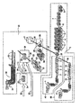
- the first production line I comprises a casting machine 1, in which thin slabs 2 are poured. These thin slabs 2 are fed to a tunnel kiln 3.
- the casting machine 1 and the tunnel kiln 3 together form a slab production line 40 (casting plant).
- the tunnel kiln 3 opens into a rolling train 4, which has six rolling stands 5 in the illustrated embodiment.
- the thin slabs 2 are rolled into hot strips 6. After leaving the rolling train 4, the rolled hot strips 6 are fed to a cooling section 7 and rolled up on a reel 8.
- the first production line I comprises a further casting machine 11.
- the casting machine 11 is arranged parallel to the casting machine 1 in terms of production technology.
- the casting machine 11 likewise produces thin slabs 12.
- These thin slabs 12 are fed to a tunnel kiln 13, which is arranged within the first production line I in terms of production technology parallel to the tunnel kiln 3.
- the casting machine 11 and the tunnel kiln 13 together form a slab production line (casting plant), which is designated by 50.
- the thin slabs 12 produced by the slab production line 50 are then likewise fed to the rolling train 4 (arrow 14).
- the slab production lines 40 and 50 form a two-strand caster.
- a second production line II is arranged.
- the second production line II comprises a slab feed device 20 in the cast roll mill shown.
- the slabs 22 can be fed to a reheating furnace 23 and to a downstream (reversing) roughing stand 24.
- the pre-bands rolled in the roughing stand 24 are received as coils 25 by a coil box 26.
- the slab feeding device 20 is in the process of the invention manufacturing technology controlled independently of the slab production line 40 and 50, respectively.
- the cast rolling mill further comprises a coil transport device, by means of which the coils 25 are transferred from the second production line II to the first production line I in front of the rolling mill 4.
- the coil transport device is not shown in the drawing for reasons of clarity.
- the coils 25 are removed from the coil box 26 and transported to the entrance of the rolling train 4.
- the feeding of the coils 25 is symbolized by an arrow 27.
- the coil box 26 is associated with a holding furnace 21 for storing the coils (double arrow 29).
- the embodiment shown is expanded by a slab production line 30.
- the slab production device 30 is in this case arranged in front of the slab feed device 20.
- the slab production line 30 includes a casting machine 31 in which slabs 22 are poured.
- the slab feeder 20 feeds the slabs 22 to the reheating furnace 23 (arrow 28).
- Both the slabs 22 produced by the slab production line 30 and the externally produced slabs are buffered in production in a slab bearing 34 (arrow 33 or arrow 35) and fed to the slab feeding device 20 as required (arrow 36, cold insert).
Landscapes
- Engineering & Computer Science (AREA)
- Mechanical Engineering (AREA)
- Metal Rolling (AREA)
- General Factory Administration (AREA)
- Continuous Casting (AREA)
Description
- Die Erfindung betrifft ein Verfahren zum Betreiben einer Gießwalzanlage (siehe z.B. die
EP-A-0584605 ). - In derartigen Gießwalzanlagen werden Brammen zu Bandmaterial verarbeitet. Die bekannten Gießwalzanlagen umfassen wenigstens eine Gießmaschine, deren Brammen ohne Zwischenlagerung wenigstens einem Tunnelofen zugeführt werden. Der Tunnelofen mündet in eine Walzstraße (Fertigstraße) mit wenigstens einem Walzgerüst. In der Walzstraße werden die Brammen zu Warmbändern gewalzt. Nach dem Verlassen der Walzstraße werden die gewalzten Warmbänder wenigstens einer Kühlstrecke zugeführt und auf wenigstens eine Haspel aufgerollt.
- Eine Gießwalzanlage ist damit durch eine Kopplung der in der konventionellen Stahlblecherzeugung entkoppelten Prozesse Brammengießen und Warmwalzen gekennzeichnet. Anlagen der Stahlindustrie bestehen somit mindestens aus drei Komponenten, nämlich dem Stahlwerk, in dem aus Roheisen Stahl erzeugt wird, der Brammen-Produktionslinie, die wenigstens eine Gießanlage (Gießmaschine mit nachgeschaltetem Tunnelofen) aufweist, und der Walzstraße (Fertigstraße). Für die maximal mögliche Produktion wird entweder mit zwei Gießanlagen mit je einem Gießstrang oder mit einer Zwei-Strang-Gießanlage gearbeitet.
- Die Walzleistung der Walzstraße kann bei den bekannten Gießanlagen zeitlich nicht voll genutzt werden, weil die Gießleistung (Gießgeschwindigkeit und Gießquerschnitt) der Gießmaschine(n) nicht über bestimmte Grenzen hinaus erhöht werden kann, um technische und qualitative Probleme zu vermeiden. Dies bedeutet trotz vollem Gießbetrieb, dass die Walzstraße schneller walzt, als die Gießmaschine bzw. die Gießmaschinen Brammen nachliefern können.
- Ein weiterer Grund für die begrenzte Produktionsleistung der bekannten Gießwalzanlagen liegt darin, dass die Zwei-Strang-Gießanlage bzw. die zwei Gießanlagen aus technischen Gründen zu bestimmten Zeiten nicht produzieren können und dadurch Produktionslücken entstehen. Die ungenutzten Produktionslücken sind u. a. die notwendigen Rüstzeiten der Gießmaschinen wegen Verteiler-, Kokillen-, oder Segmentwechsels, die geplanten Stillstandszeiten wegen Wartungsarbeiten, sowie die ungeplanten Stillstandszeiten wegen Störungen im Gießbetrieb. Dies bedeutet, dass die Walzstraße dann entweder überhaupt nicht oder nur mit vergrößerten Pausen walzen kann.
- Damit bilden die beiden Brammen-Produktionslinien für die Leistung der Walzstraße einen Produktionsengpass, der zu einer reduzierten Jahresproduktionsleistung der Gießwalzanlage führt.
- Aufgabe der vorliegenden Erfindung ist es deshalb, ein Verfahren zum Betreiben einer Gießwalzanlage zu schaffen, mit dem eine höhere Durchsatzmenge bei der Produktion von Bandmaterial realisiert werden kann.
- Die Aufgabe wird erfindungsgemäß durch ein Verfahren mit den Merkmalen von Anspruch 1 gelöst. Vorteilhafte Ausgestaltungen des erfindungsgemäßen Verfahrens sind jeweils Gegenstand von weiteren Ansprüchen.
- Das Verfahren nach Anspruch 1 ist zum Betreiben einer Gießwalzanlage geeignet, die wenigstens eine Brammen-Produktionslinie und wenigstens eine Walzstraße sowie mindestens eine Brammen-Zuführungseinrichtung umfasst, die fertigungstechnisch von der Brammen-Produktionslinie unabhängig ist. Während einer Produktionspause der Brammen-Produktionslinie übernimmt die Brammen-Zuführungseinrichtung die Brammenzufuhr zur Walzstraße gemäß logistischer und/oder produktionstechnischer Vorgaben bis zum maximal realisierbaren Umfang.
- Die Erfindung nutzt damit bisher nicht genutzte Walzpausen der Gießwalzanlage durch optimierte logistische Vorgaben in einer modifizierten Anlagenkonfiguration, die eine Brammen-Zuführungseinrichtung enthält.
- Die Erfindung stellt ein geeignetes Produktionsplanungsverfahren zur Verfügung, die auf die Art der erweiterten Konfiguration der Gießwalzanlage abgestimmt ist. Die durch die Brammen-Zuführungseinrichtung gelieferten Brammen werden zusätzlich in der Walzstraße gewalzt, ohne dass die grundsätzliche Ausstattung der speziell konfigurierten Gießwalzanlage verändert werden muss. Dadurch kann die Durchsatzmenge bei der Produktion von Bandmaterial wesentlich gesteigert werden.
- Eine zusätzliche konventionelle Brammen-Produktionslinie, die dicke Brammen über mindestens einen Erwärmungsofen und über wenigstens ein (Reversier-)Vorgerüst zu Dünnbrammen walzt, und diese über einen Warmhalteofen an der Walzstraße bereitstellt. Diese Konfiguration wird man wählen, wenn die zusätzliche Brammen-Produktionslinie Stahlqualitäten produzieren soll, die keine hohen Gießgeschwindigkeiten vertragen, also z. B. Edelstähle. Damit kann eine mit dem erfindungsgemäßen Verfahren betriebene Gießwalzanlage Normalstähle und Edelstähle mit hoher Gesamtjahresproduktion liefern.
- Beim erfindungsgemäßen Verfahren kommt es also nur darauf an, dass der Brammen-Zuführungseinrichtung der Gießwalzanlage Brammen entsprechend logistischer und/oder produktionstechnischer Vorgaben zugeführt werden. Es kommt damit insbesondere nicht auf die Art der weiteren Brammen-Produktionslinie an.
- Durch die Erfindung werden optimierte Produktionspläne für den Betrieb der Gießwalzanlage mit voller Auslastung der Walzstraße erzeugt.
- Aus derartigen Produktionsplänen können die Anlagenpläne für die einzelnen Anlagenteile der Gießwalzanlage abgeleitet werden. Diese sind Schmelzenpläne und Gießpläne sowie Brammen-Einsatzpläne und Walzpläne.
- Durch die Schmelzenpläne werden die notwendigen Schmelzenfolgen in mindestens einem der Gießwalzanlage zugeordneten Stahlwerk erstellt, und zwar inklusive der zeitlichen Abfolge zur rechtzeitigen Anlieferung der Schmelzen an den Gießmaschinen.
- Die Gießpläne beschreiben die Erzeugung der Dünnbrammen in den Gießmaschinen der Gießwalzanlage bzw. in der konventionellen Gießmaschine der weiteren Brammen-Produktionslinie, inklusive der Gießsequenzfolge, der Schmelzenfolge und der Brammenfolge für jede Brammen-Produktionslinie.
- Die Brammen-Einsatzpläne bestimmen den Einsatz der Brammen in der weiteren Brammen-Produktionslinie in Abhängigkeit von Kalt-, Warm- oder Heißeinsatz. Dabei ist insbesondere die Reihenfolge und die zeitliche Abfolge so zu planen, dass die Brammen rechtzeitig an der Walzstraße zur Nutzung bisher ungenutzter Walzpausen in der Gießwalzanlage bereit stehen.
- Durch die Walzpläne wird die Walzung der Brammen aus allen Brammen-Produktionslinien, inklusive Taktung des Brammen-Einsatzes aus dem Tunnelofen der Gießwalzanlage, derart geplant, dass die Walzpausen günstig durch die weitere Brammen-Produktionslinie genutzt werden können. Außerdem findet eine Planung der in der Walzstraße notwendigen Walzenwechsel unter Berücksichtigung der Pufferzeiten in den Öfen statt.
- Bei allen Planungsschritten sind zwingende und weiche Restriktionen (technische Regeln) zu berücksichtigen. Dabei müssen zwingende Restriktionen auf jeden Fall eingehalten werden, wohingegen weiche Restriktionen durch sogenannte Kostenfunktionen optimiert werden können. Damit entstehen nicht nur gültige und ausführbare Produktionspläne, sondern auch kostenoptimierte und durchsatzoptimierte Produktionspläne.
- Ein Ausführungsbeispiel des erfindungsgemäßen Verfahrens wird nachfolgend anhand einer in der Zeichnung schematisch dargestellten Gießwalzanlage näher erläutert.
- In der Zeichnung ist mit I eine erste Fertigungslinie bezeichnet. Die erste Fertigungslinie I umfasst eine Gießmaschine 1, in der Dünnbrammen 2 gegossen werden. Diese Dünnbrammen 2 werden einem Tunnelofen 3 zugeführt. Die Gießmaschine 1 und der Tunnelofen 3 bilden zusammen eine Brammen-Produktionslinie 40 (Gießanlage). Der Tunnelofen 3 mündet in eine Walzstraße 4, die im dargestellten Ausführungsbeispiel sechs Walzgerüste 5 aufweist. In der Walzstraße 4 werden die Dünnbrammen 2 zu Warmbändern 6 gewalzt. Nach dem Verlassen der Walzstraße 4 werden die gewalzten Warmbänder 6 einer Kühlstrecke 7 zugeführt und auf eine Haspel 8 aufgerollt.
- Bei der in der Zeichnung dargestellten Gießwalzanlage umfasst die erste Fertigungslinie I eine weitere Gießmaschine 11. Die Gießmaschine 11 ist fertigungstechnisch parallel zur Gießmaschine 1 angeordnet. Die Gießmaschine 11 erzeugt ebenfalls Dünnbrammen 12. Diese Dünnbrammen 12 werden einem Tunnelofen 13 zugeführt, der innerhalb der ersten Fertigungslinie I fertigungstechnisch parallel zum Tunnelofen 3 angeordnet ist. Die Gießmaschine 11 und der Tunnelofen 13 bilden zusammen eine Brammen-Produktionslinie (Gießanlage), die mit 50 bezeichnet ist. Die von der Brammen-Produktionslinie 50 erzeugten Dünnbrammen 12 werden anschließend ebenfalls der Walzstraße 4 zugeführt (Pfeil 14).
- Die Brammen-Produktionslinien 40 und 50 bilden eine Zwei-Strang-Gießanlage.
- Zumindest teilweise fertigungstechnisch parallel zur ersten Fertigungslinie I ist eine zweite Fertigungslinie II angeordnet. Die zweite Fertigungslinie II umfasst bei der dargestellten Gießwalzanlage eine Brammen-Zuführungseinrichtung 20. Durch diese Brammen-Zuführungseinrichtung 20 sind die Brammen 22 einem Wiedererwärmungsofen 23 und einem nachgeordneten (Reversier-)Vorgerüst 24 zuführbar. Die im Vorgerüst 24 gewalzten Vorbänder werden als Coils 25 von einer Coil-Box 26 aufgenommen.
- Die Brammen-Zuführungseinrichtung 20 wird bei dem erfindungsgemäßen Verfahren fertigungstechnisch unabhängig von der Brammen-Produktionslinie 40 bzw. 50 gesteuert.
- Die Gießwalzanlage umfasst weiterhin eine Coil-Transporteinrichtung, durch die die Coils 25 vor der Walzstraße 4 von der zweiten Fertigungslinie II in die erste Fertigungslinie I überführt werden. Die Coil-Transporteinrichtung ist aus Gründen der Übersichtlichkeit in der Zeichnung nicht dargestellt. Zur Zuführung der Vorbänder werden die Coils 25 aus der Coil-Box 26 entnommen und an den Eingang der Walzstraße 4 transportiert Die Zuführung der Coils 25 ist durch einen Pfeil 27 symbolisiert.
- Bei der in der Zeichnung dargestellten Ausgestaltung ist der Coil-Box 26 ein Warmhalteofen 21 zur Aufbewahrung der Coils zugeordnet (Doppelpfeil 29).
- Zusätzlich ist die gezeigte Ausführungsform durch eine Brammen-Produktionslinie 30 erweitert. Die Brammen-Fertigungseinrichtung 30 ist hierbei vor der Brammen-Zuführungseinrichtung 20 angeordnet. Die Brammen-Produktionslinie 30 umfasst eine Gießmaschine 31, in der Brammen 22 gegossen werden. Die Brammen-Zuführungseinrichtung 20 führt die Brammen 22 dem Wiedererwärmungsofen 23 zu (Pfeil 28).
- Bei der in der Zeichnung dargestellten Ausführungsform werden der Brammen-Zuführungseinrichtung 20 fremdproduzierte Brammen zugeführt werden (Kalteinsatz). Die Zuführung der fremdproduzierten Brammen ist durch einen Pfeil 32 symbolisiert. Diese ist Zuführung ist nicht Gegenstand der Erfindung.
- Sowohl die von der Brammen-Produktionslinie 30 erzeugten Brammen 22 als auch die fremdproduzierten Brammen werden in einem Brammenlager 34 fertigungstechnisch gepuffert (Pfeil 33 bzw. Pfeil 35) und bedarfsweise der Brammen-Zuführungseinrichtung 20 zugeführt (Pfeil 36, Kalteinsatz).
Claims (3)
- Verfahren zum Betreiben einer Gießwalzanlage, die eine erste Fertigungslinie (I) mit wenigstens einer Brammen-Produktionslinie (40, 50) und wenigstens einer Walzstraße (4) sowie eine zweite Fertigungslinie (II) mit einer Brammen-Produktionsline (30) und mit wenigstens einer Brammen-Zuführungseinrichtung (20) umfasst, wobei die Brammen-Zuführungseinrichtung (20) fertigungstechnisch unabhängig von der Brammen-Produktionslinie (40, 50) ist, wobei während einer Produktionspause der Brammen-Produktionslinie (40, 50) die Brammen-Zuführungseinrichtung (20) die Brammenzufuhr von ihr von der weiteren Brammen-Produktionslinie (30) der zweiten Fertigungslinie (II) oder fremdproduzierten zugeführten Brammen zur Walzstraße (4) gemäß logistischer und/oder produktionstechnischer Vorgaben bis zum maximal realisierbaren Umfang übernimmt, wobei sowohl die von der weiteren Brammen-Produktionslinie (30) erzeugten Brammen (22) als auch die fremdproduzierten Brammen in einem Brammenlager (34) fertigungstechnisch gepuffert werden und von dort aus der Brammen-Zuführungseinrichtung (20) zugeführt werden.
- Verfahren nach Anspruch 1, wobei die Brammen-Produktionslinie (40, 50) der Gießwalzanlage als Dünnbrammen-Produktionslinie ausgebildet ist.
- Verfahren nach Anspruch 1, wobei die weitere Brammen-Produktionsline (30) als Dickbrammen-Produktionslinie ausgebildet ist, die zusammen mit der Brammen-Produktionslinie (40, 50) die Brammenzufuhr zur Walzstraße (4) gemäß logistischer und/oder produktionstechnischer Vorgaben bis zum maximal realisierbaren Umfang übernimmt.
Applications Claiming Priority (3)
| Application Number | Priority Date | Filing Date | Title |
|---|---|---|---|
| DE10109223A DE10109223C1 (de) | 2001-02-26 | 2001-02-26 | Verfahren zum Betreiben einer Gießwalzanlage |
| DE10109223 | 2001-02-26 | ||
| PCT/DE2002/000612 WO2002068137A1 (de) | 2001-02-26 | 2002-02-20 | Verfahren zum betreiben einer giesswalzanlage |
Publications (3)
| Publication Number | Publication Date |
|---|---|
| EP1363750A1 EP1363750A1 (de) | 2003-11-26 |
| EP1363750B1 EP1363750B1 (de) | 2004-09-22 |
| EP1363750B2 true EP1363750B2 (de) | 2010-07-28 |
Family
ID=7675540
Family Applications (1)
| Application Number | Title | Priority Date | Filing Date |
|---|---|---|---|
| EP02712795A Expired - Lifetime EP1363750B2 (de) | 2001-02-26 | 2002-02-20 | Verfahren zum betreiben einer giesswalzanlage |
Country Status (7)
| Country | Link |
|---|---|
| US (1) | US6941636B2 (de) |
| EP (1) | EP1363750B2 (de) |
| JP (1) | JP2004522588A (de) |
| CN (1) | CN100335186C (de) |
| AT (1) | ATE276842T1 (de) |
| DE (2) | DE10109223C1 (de) |
| WO (1) | WO2002068137A1 (de) |
Families Citing this family (12)
| Publication number | Priority date | Publication date | Assignee | Title |
|---|---|---|---|---|
| DE10304318C5 (de) * | 2003-02-04 | 2015-10-15 | Sms Group Gmbh | Verfahren zum Walzen von dünnen und/oder dicken Brammen aus Stahlwerkstoffen zu Warmband |
| US20120018113A1 (en) * | 2004-12-03 | 2012-01-26 | Joachim Schwellenbach | CSP-continuous casting plant with an additional rolling line |
| DE102004058550A1 (de) * | 2004-12-03 | 2006-06-14 | Sms Demag Ag | CSP-Stranggießanlage mit Rollenherdofen und Schwenkfähren |
| DE102008003222A1 (de) * | 2007-09-13 | 2009-03-19 | Sms Demag Ag | Kompakte flexible CSP-Anlage für Endlos-, Semi-Endlos- und Batchbetrieb |
| DE102007057423A1 (de) * | 2007-11-29 | 2009-06-04 | Sms Demag Ag | Fräsmaschine zum Fräsen einer Bramme |
| DE102011008434A1 (de) | 2011-01-12 | 2012-07-12 | Sms Siemag Ag | Anlage und Verfahren zum Erzeugen von Warmband |
| CN103625880B (zh) * | 2012-08-24 | 2015-12-02 | 宝山钢铁股份有限公司 | 一种叠加式物流输送系统的控制方法 |
| ITUD20130128A1 (it) * | 2013-10-04 | 2015-04-05 | Danieli Off Mecc | Impianto siderurgico a linea di co-laminazione multipla e relativo metodo di produzione |
| EP3094425B1 (de) | 2014-01-17 | 2018-06-20 | Danieli & C. Officine Meccaniche, S.p.A. | Anlage und verfahren zur produktion von metallprodukten |
| IT201800010870A1 (it) * | 2018-12-06 | 2020-06-06 | Danieli Off Mecc | Apparato e metodo di produzione di nastri |
| CN113770344A (zh) * | 2021-08-31 | 2021-12-10 | 中冶赛迪工程技术股份有限公司 | 一种铸造坯料清理堆存区的布置结构及运行方法 |
| DE102024126755A1 (de) * | 2024-09-17 | 2026-03-19 | Sms Group Gmbh | Anlage und Verfahren zum Herstellen eines Materialbands und Verwendung einer Wärmebehandlungsvorrichtung |
Citations (2)
| Publication number | Priority date | Publication date | Assignee | Title |
|---|---|---|---|---|
| JPS6156705A (ja) † | 1984-08-28 | 1986-03-22 | Ishikawajima Harima Heavy Ind Co Ltd | 圧延設備 |
| EP0665296A1 (de) † | 1994-01-26 | 1995-08-02 | INNSE INNOCENTI ENGINEERING S.p.A. | Verfahren und Anlage zum Herstellen warmgewalzter Stahlbänder |
Family Cites Families (32)
| Publication number | Priority date | Publication date | Assignee | Title |
|---|---|---|---|---|
| NL8001197A (nl) | 1980-02-28 | 1981-10-01 | Estel Hoogovens Bv | Werkwijze voor het in aanzienlijke mate plastisch reduceren van de breedte van een plat voorprodukt door walsen. |
| JPS57146404A (en) | 1981-03-07 | 1982-09-09 | Kawasaki Steel Corp | Hot rolling line for slab by plural continuous casting installations of different kinds |
| JPS57146403A (en) | 1981-03-07 | 1982-09-09 | Kawasaki Steel Corp | Hot rolling line for slab by plural continuous casting installations of different kinds |
| JPS57149007A (en) | 1981-03-12 | 1982-09-14 | Kawasaki Steel Corp | Hot rolling line of different-kind and plural slabs by continuous casting equipment |
| JPS58122107A (ja) | 1982-01-18 | 1983-07-20 | Hitachi Ltd | 連続薄板直接圧延設備 |
| FR2579784B1 (fr) | 1985-03-26 | 1987-06-19 | Produits Ind Cie Fse | Procede et installation permettant, d'une part, de connaitre d'avance a un instant donne le resultat auquel conduit necessairement un milieu chimique evolutif donne et, d'autre part, d'assurer la regulation de ce milieu pour parvenir a un resultat determine fixe a l'avance |
| JPS6254501A (ja) | 1985-09-02 | 1987-03-10 | Kawasaki Steel Corp | 連続鋳造ライン及び熱間圧延ラインのレイアウト |
| IT1214200B (it) | 1987-08-05 | 1990-01-10 | Danieli Off Mecc | Impianto e procedimento di equalizzazione temperatura bramme a valle colata continua. |
| WO1989008512A1 (fr) | 1988-03-17 | 1989-09-21 | Mannesmann Ag | Installation pour la fabrication de rubans d'acier lamines a chaud |
| DE4001288A1 (de) * | 1990-01-18 | 1991-07-25 | Schloemann Siemag Ag | Anlage zum auswalzen von warmbreitband |
| JP3152241B2 (ja) | 1990-06-12 | 2001-04-03 | 株式会社日立製作所 | 熱間薄板製造設備及び製造方法 |
| DE69225723T2 (de) | 1991-01-22 | 1998-12-03 | Honeywell, Inc., Minneapolis, Minn. | Zweistufige Systemidentifikationsvorrichtung mit Optimierung |
| EP0524317A4 (en) | 1991-02-08 | 1995-02-15 | Tokyo Shibaura Electric Co | Model forecasting controller |
| US5276952A (en) * | 1992-05-12 | 1994-01-11 | Tippins Incorporated | Method and apparatus for intermediate thickness slab caster and inline hot strip and plate line |
| US5544408A (en) * | 1992-05-12 | 1996-08-13 | Tippins Incorporated | Intermediate thickness slab caster and inline hot strip and plate line with slab sequencing |
| IT1259487B (it) * | 1992-08-26 | 1996-03-20 | Danieli Off Mecc | Procedimento per la produzione di lamiere sottili ed impianto di laminazione compatto adottante tale procedimento |
| US5740033A (en) | 1992-10-13 | 1998-04-14 | The Dow Chemical Company | Model predictive controller |
| JP2989737B2 (ja) | 1993-11-25 | 1999-12-13 | 勝彦 山田 | 鋼材の連続鋳造法および連続鋳造・圧延法 |
| US5519605A (en) | 1994-10-24 | 1996-05-21 | Olin Corporation | Model predictive control apparatus and method |
| DE19529049C1 (de) * | 1995-07-31 | 1997-03-20 | Mannesmann Ag | Hochgeschwindigkeits-Dünnbrammenanlage |
| JP3160519B2 (ja) | 1996-01-18 | 2001-04-25 | 三菱重工業株式会社 | 熱間圧延ライン |
| IT1288842B1 (it) | 1996-01-26 | 1998-09-25 | Simac Spa | Metodo e rispettivo impianto di laminazione a caldo per la produzione in continuo di barre, tondini o filo |
| NL1007739C2 (nl) * | 1997-12-08 | 1999-06-09 | Hoogovens Staal Bv | Werkwijze en inrichting voor het vervaardigen van een stalen band met hoge sterkte. |
| US6026334A (en) | 1996-07-30 | 2000-02-15 | Weyerhaeuser Company | Control system for cross-directional profile sheet formation |
| KR100205691B1 (ko) | 1997-04-29 | 1999-07-01 | 정순착 | 공정 제어용 혼성예측자 및 혼성 예측 방법 |
| ATE317308T1 (de) | 1997-11-26 | 2006-02-15 | Ishikawajima Harima Heavy Ind | Verfahren zur herstellung eines warmgewalzten stahlbandes |
| NL1007730C2 (nl) | 1997-12-08 | 1999-06-09 | Hoogovens Staal Bv | Inrichting en werkwijze voor het vervaardigen van een stalen band. |
| DE19839370A1 (de) * | 1998-08-28 | 2000-03-09 | Schloemann Siemag Ag | Verfahren und Anlage zur Herstellung von Warmbreitband aus insbesondere dünnen Brammen |
| EP1055180B1 (de) | 1998-12-03 | 2011-07-20 | Siemens Aktiengesellschaft | Verfahren und anordnung zum entwurf eines technischen systems |
| DE19953252A1 (de) | 1999-11-04 | 2001-05-10 | Sms Demag Ag | Verfahren zur Oberflächenbearbeitung eines kontinuierlich gegossenen Stahlproduktes und Einrichtung hierzu |
| DE10045085C2 (de) | 2000-09-12 | 2002-07-18 | Siemens Ag | Gießwalzanlage |
| ITPN20010010A1 (it) | 2001-02-15 | 2002-08-16 | Sms Demag Aktiengesellshaft | Gabbia di laminazione verticale per impianto di laminazione a caldo per la produzione in parallelo simultanea di barre o fili. |
-
2001
- 2001-02-26 DE DE10109223A patent/DE10109223C1/de not_active Expired - Lifetime
-
2002
- 2002-02-20 WO PCT/DE2002/000612 patent/WO2002068137A1/de not_active Ceased
- 2002-02-20 EP EP02712795A patent/EP1363750B2/de not_active Expired - Lifetime
- 2002-02-20 AT AT02712795T patent/ATE276842T1/de active
- 2002-02-20 JP JP2002567484A patent/JP2004522588A/ja active Pending
- 2002-02-20 CN CNB028050223A patent/CN100335186C/zh not_active Expired - Fee Related
- 2002-02-20 DE DE50201107T patent/DE50201107D1/de not_active Expired - Lifetime
-
2003
- 2003-08-26 US US10/648,574 patent/US6941636B2/en not_active Expired - Fee Related
Patent Citations (2)
| Publication number | Priority date | Publication date | Assignee | Title |
|---|---|---|---|---|
| JPS6156705A (ja) † | 1984-08-28 | 1986-03-22 | Ishikawajima Harima Heavy Ind Co Ltd | 圧延設備 |
| EP0665296A1 (de) † | 1994-01-26 | 1995-08-02 | INNSE INNOCENTI ENGINEERING S.p.A. | Verfahren und Anlage zum Herstellen warmgewalzter Stahlbänder |
Also Published As
| Publication number | Publication date |
|---|---|
| WO2002068137A1 (de) | 2002-09-06 |
| DE10109223C1 (de) | 2002-08-01 |
| US20040034987A1 (en) | 2004-02-26 |
| ATE276842T1 (de) | 2004-10-15 |
| US6941636B2 (en) | 2005-09-13 |
| EP1363750B1 (de) | 2004-09-22 |
| EP1363750A1 (de) | 2003-11-26 |
| CN1491137A (zh) | 2004-04-21 |
| JP2004522588A (ja) | 2004-07-29 |
| CN100335186C (zh) | 2007-09-05 |
| DE50201107D1 (de) | 2004-10-28 |
Similar Documents
| Publication | Publication Date | Title |
|---|---|---|
| EP1363750B2 (de) | Verfahren zum betreiben einer giesswalzanlage | |
| DE69606137T2 (de) | Verfahren und Anlage zum Walzen von Bänder und Blechen | |
| DE69701196T2 (de) | Verfahren zum kontinuierlichen Walzen von Blechen und/oder Bänder und entsprechende kontinuierliche Walzstrasse | |
| DE10304318B4 (de) | Verfahren zum Walzen von dünnen und/oder dicken Brammen aus Stahlwerkstoffen zu Warmband | |
| EP0889762A1 (de) | Verfahren und anlage zur herstellung von warmgewalztem stahlband | |
| EP0595282B2 (de) | Verfahren und Anlage zur Herstellung von warmgewalztem Stahlband, insbesondere aus bandförmig stranggegossenem Vormaterial | |
| WO2004004938A1 (de) | Verfahren und giesswalzanlage zum semi-endloswalzen oder endloswalzen durch giessen eines metalls insbesondere eines stahlstrangs, der nach dem erstarren bei bedarf quergeteilt wird | |
| DE4234454A1 (de) | Verfahren und Anlage zur Herstellung von warmgewalzten Bändern oder Profilen aus stranggegossenem Vormaterial | |
| EP2427281B1 (de) | Verfahren zum herstellen eines in einer walzstrasse einer walzanlage gewalzten walzguts, steuer- und/oder regeleinrichtung für eine walzanlage zur herstellung von gewalztem walzgut, walzanlage zur herstellung von gewalztem walzgut, maschinenlesbarer programmcode und speichermedium | |
| DE4041206C2 (de) | Verfahren und Anlage zur Herstellung von warmgewalztem Stahlband, insbesondere für Edelstähle aus stranggegossenem Vormaterial | |
| EP1601479A1 (de) | Giesswalzanlage zum erzeugen eines stahlbandes | |
| EP1317325B1 (de) | Giesswalzanlage | |
| EP0761325A1 (de) | Verfahren und Anlage zur Herstellung von ferritisch warmgewalztem Band | |
| EP4537950A1 (de) | Anlage und verfahren zum herstellen eines metallbandes im endlosbetrieb oder im batchbetrieb | |
| EP0893168B1 (de) | Verfahren zur Herstellung von 0.5 mm dicken Warmband in einer Warmbandstrasse | |
| WO1999058263A1 (de) | Anordnung und verfahren zum erzeugen von stahlband | |
| DE19732538A1 (de) | Warmbandstraße für 0,5 mm dickes Warmband | |
| DE19749706C1 (de) | Verfahren zur Herstellung von dünnem warmgewalztem Stahlband | |
| DE19749716A1 (de) | Warmbandstraße für 0,5 mm dickes Warmband |
Legal Events
| Date | Code | Title | Description |
|---|---|---|---|
| PUAI | Public reference made under article 153(3) epc to a published international application that has entered the european phase |
Free format text: ORIGINAL CODE: 0009012 |
|
| 17P | Request for examination filed |
Effective date: 20030711 |
|
| AK | Designated contracting states |
Kind code of ref document: A1 Designated state(s): AT BE CH CY DE DK ES FI FR GB GR IE IT LI LU MC NL PT SE TR |
|
| GRAP | Despatch of communication of intention to grant a patent |
Free format text: ORIGINAL CODE: EPIDOSNIGR1 |
|
| GRAS | Grant fee paid |
Free format text: ORIGINAL CODE: EPIDOSNIGR3 |
|
| GRAA | (expected) grant |
Free format text: ORIGINAL CODE: 0009210 |
|
| AK | Designated contracting states |
Kind code of ref document: B1 Designated state(s): AT BE CH CY DE DK ES FI FR GB GR IE IT LI LU MC NL PT SE TR |
|
| PG25 | Lapsed in a contracting state [announced via postgrant information from national office to epo] |
Ref country code: TR Free format text: LAPSE BECAUSE OF FAILURE TO SUBMIT A TRANSLATION OF THE DESCRIPTION OR TO PAY THE FEE WITHIN THE PRESCRIBED TIME-LIMIT Effective date: 20040922 Ref country code: NL Free format text: LAPSE BECAUSE OF FAILURE TO SUBMIT A TRANSLATION OF THE DESCRIPTION OR TO PAY THE FEE WITHIN THE PRESCRIBED TIME-LIMIT Effective date: 20040922 Ref country code: GB Free format text: LAPSE BECAUSE OF FAILURE TO SUBMIT A TRANSLATION OF THE DESCRIPTION OR TO PAY THE FEE WITHIN THE PRESCRIBED TIME-LIMIT Effective date: 20040922 Ref country code: IE Free format text: LAPSE BECAUSE OF FAILURE TO SUBMIT A TRANSLATION OF THE DESCRIPTION OR TO PAY THE FEE WITHIN THE PRESCRIBED TIME-LIMIT Effective date: 20040922 |
|
| REG | Reference to a national code |
Ref country code: GB Ref legal event code: FG4D Free format text: NOT ENGLISH |
|
| REG | Reference to a national code |
Ref country code: CH Ref legal event code: EP |
|
| REG | Reference to a national code |
Ref country code: IE Ref legal event code: FG4D Free format text: GERMAN |
|
| REF | Corresponds to: |
Ref document number: 50201107 Country of ref document: DE Date of ref document: 20041028 Kind code of ref document: P |
|
| PG25 | Lapsed in a contracting state [announced via postgrant information from national office to epo] |
Ref country code: GR Free format text: LAPSE BECAUSE OF FAILURE TO SUBMIT A TRANSLATION OF THE DESCRIPTION OR TO PAY THE FEE WITHIN THE PRESCRIBED TIME-LIMIT Effective date: 20041222 Ref country code: DK Free format text: LAPSE BECAUSE OF FAILURE TO SUBMIT A TRANSLATION OF THE DESCRIPTION OR TO PAY THE FEE WITHIN THE PRESCRIBED TIME-LIMIT Effective date: 20041222 |
|
| REG | Reference to a national code |
Ref country code: SE Ref legal event code: TRGR |
|
| PG25 | Lapsed in a contracting state [announced via postgrant information from national office to epo] |
Ref country code: ES Free format text: LAPSE BECAUSE OF FAILURE TO SUBMIT A TRANSLATION OF THE DESCRIPTION OR TO PAY THE FEE WITHIN THE PRESCRIBED TIME-LIMIT Effective date: 20050102 |
|
| PG25 | Lapsed in a contracting state [announced via postgrant information from national office to epo] |
Ref country code: LU Free format text: LAPSE BECAUSE OF NON-PAYMENT OF DUE FEES Effective date: 20050220 Ref country code: CY Free format text: LAPSE BECAUSE OF FAILURE TO SUBMIT A TRANSLATION OF THE DESCRIPTION OR TO PAY THE FEE WITHIN THE PRESCRIBED TIME-LIMIT Effective date: 20050220 |
|
| PG25 | Lapsed in a contracting state [announced via postgrant information from national office to epo] |
Ref country code: MC Free format text: LAPSE BECAUSE OF NON-PAYMENT OF DUE FEES Effective date: 20050228 |
|
| NLV1 | Nl: lapsed or annulled due to failure to fulfill the requirements of art. 29p and 29m of the patents act | ||
| GBV | Gb: ep patent (uk) treated as always having been void in accordance with gb section 77(7)/1977 [no translation filed] |
Effective date: 20040922 |
|
| REG | Reference to a national code |
Ref country code: IE Ref legal event code: FD4D |
|
| PLAQ | Examination of admissibility of opposition: information related to despatch of communication + time limit deleted |
Free format text: ORIGINAL CODE: EPIDOSDOPE2 |
|
| PLBQ | Unpublished change to opponent data |
Free format text: ORIGINAL CODE: EPIDOS OPPO |
|
| PLAQ | Examination of admissibility of opposition: information related to despatch of communication + time limit deleted |
Free format text: ORIGINAL CODE: EPIDOSDOPE2 |
|
| PLAR | Examination of admissibility of opposition: information related to receipt of reply deleted |
Free format text: ORIGINAL CODE: EPIDOSDOPE4 |
|
| PLBQ | Unpublished change to opponent data |
Free format text: ORIGINAL CODE: EPIDOS OPPO |
|
| PLBI | Opposition filed |
Free format text: ORIGINAL CODE: 0009260 |
|
| PLAX | Notice of opposition and request to file observation + time limit sent |
Free format text: ORIGINAL CODE: EPIDOSNOBS2 |
|
| ET | Fr: translation filed | ||
| 26 | Opposition filed |
Opponent name: SMS DEMAG AG Effective date: 20050621 |
|
| PLAF | Information modified related to communication of a notice of opposition and request to file observations + time limit |
Free format text: ORIGINAL CODE: EPIDOSCOBS2 |
|
| PLBB | Reply of patent proprietor to notice(s) of opposition received |
Free format text: ORIGINAL CODE: EPIDOSNOBS3 |
|
| PG25 | Lapsed in a contracting state [announced via postgrant information from national office to epo] |
Ref country code: CH Free format text: LAPSE BECAUSE OF NON-PAYMENT OF DUE FEES Effective date: 20060228 Ref country code: LI Free format text: LAPSE BECAUSE OF NON-PAYMENT OF DUE FEES Effective date: 20060228 |
|
| REG | Reference to a national code |
Ref country code: CH Ref legal event code: PL |
|
| PG25 | Lapsed in a contracting state [announced via postgrant information from national office to epo] |
Ref country code: PT Free format text: LAPSE BECAUSE OF NON-PAYMENT OF DUE FEES Effective date: 20050222 |
|
| APAH | Appeal reference modified |
Free format text: ORIGINAL CODE: EPIDOSCREFNO |
|
| APBP | Date of receipt of notice of appeal recorded |
Free format text: ORIGINAL CODE: EPIDOSNNOA2O |
|
| APBQ | Date of receipt of statement of grounds of appeal recorded |
Free format text: ORIGINAL CODE: EPIDOSNNOA3O |
|
| APBU | Appeal procedure closed |
Free format text: ORIGINAL CODE: EPIDOSNNOA9O |
|
| PUAH | Patent maintained in amended form |
Free format text: ORIGINAL CODE: 0009272 |
|
| STAA | Information on the status of an ep patent application or granted ep patent |
Free format text: STATUS: PATENT MAINTAINED AS AMENDED |
|
| 27A | Patent maintained in amended form |
Effective date: 20100728 |
|
| AK | Designated contracting states |
Kind code of ref document: B2 Designated state(s): AT BE CH CY DE DK ES FI FR GB GR IE IT LI LU MC NL PT SE TR |
|
| REG | Reference to a national code |
Ref country code: ES Ref legal event code: FD2A Effective date: 20050221 |
|
| REG | Reference to a national code |
Ref country code: SE Ref legal event code: RPEO |
|
| PG25 | Lapsed in a contracting state [announced via postgrant information from national office to epo] |
Ref country code: IT Free format text: LAPSE BECAUSE OF NON-PAYMENT OF DUE FEES Effective date: 20100220 |
|
| PGFP | Annual fee paid to national office [announced via postgrant information from national office to epo] |
Ref country code: FI Payment date: 20120213 Year of fee payment: 11 |
|
| PG25 | Lapsed in a contracting state [announced via postgrant information from national office to epo] |
Ref country code: FI Free format text: LAPSE BECAUSE OF NON-PAYMENT OF DUE FEES Effective date: 20130220 |
|
| REG | Reference to a national code |
Ref country code: FR Ref legal event code: PLFP Year of fee payment: 14 |
|
| REG | Reference to a national code |
Ref country code: DE Ref legal event code: R081 Ref document number: 50201107 Country of ref document: DE Owner name: PRIMETALS TECHNOLOGIES GERMANY GMBH, DE Free format text: FORMER OWNER: SIEMENS AKTIENGESELLSCHAFT, 80333 MUENCHEN, DE |
|
| REG | Reference to a national code |
Ref country code: FR Ref legal event code: TP Owner name: PRIMETALS TECHNOLOGIES GERMANY GMBH, DE Effective date: 20151105 |
|
| REG | Reference to a national code |
Ref country code: FR Ref legal event code: PLFP Year of fee payment: 15 |
|
| PGFP | Annual fee paid to national office [announced via postgrant information from national office to epo] |
Ref country code: IT Payment date: 20160223 Year of fee payment: 15 Ref country code: DE Payment date: 20160218 Year of fee payment: 15 |
|
| PGFP | Annual fee paid to national office [announced via postgrant information from national office to epo] |
Ref country code: BE Payment date: 20160217 Year of fee payment: 15 Ref country code: SE Payment date: 20160217 Year of fee payment: 15 Ref country code: AT Payment date: 20160218 Year of fee payment: 15 Ref country code: FR Payment date: 20160218 Year of fee payment: 15 |
|
| REG | Reference to a national code |
Ref country code: AT Ref legal event code: PC Ref document number: 276842 Country of ref document: AT Kind code of ref document: T Owner name: PRIMETALS TECHNOLOGIES GERMANY GMBH, DE Effective date: 20170227 |
|
| PG25 | Lapsed in a contracting state [announced via postgrant information from national office to epo] |
Ref country code: BE Free format text: LAPSE BECAUSE OF NON-PAYMENT OF DUE FEES Effective date: 20170228 |
|
| REG | Reference to a national code |
Ref country code: DE Ref legal event code: R119 Ref document number: 50201107 Country of ref document: DE |
|
| REG | Reference to a national code |
Ref country code: SE Ref legal event code: EUG |
|
| REG | Reference to a national code |
Ref country code: AT Ref legal event code: MM01 Ref document number: 276842 Country of ref document: AT Kind code of ref document: T Effective date: 20170220 |
|
| PG25 | Lapsed in a contracting state [announced via postgrant information from national office to epo] |
Ref country code: AT Free format text: LAPSE BECAUSE OF NON-PAYMENT OF DUE FEES Effective date: 20170220 |
|
| PG25 | Lapsed in a contracting state [announced via postgrant information from national office to epo] |
Ref country code: SE Free format text: LAPSE BECAUSE OF NON-PAYMENT OF DUE FEES Effective date: 20170221 |
|
| REG | Reference to a national code |
Ref country code: FR Ref legal event code: ST Effective date: 20171031 |
|
| PG25 | Lapsed in a contracting state [announced via postgrant information from national office to epo] |
Ref country code: DE Free format text: LAPSE BECAUSE OF NON-PAYMENT OF DUE FEES Effective date: 20170901 Ref country code: FR Free format text: LAPSE BECAUSE OF NON-PAYMENT OF DUE FEES Effective date: 20170228 |
|
| REG | Reference to a national code |
Ref country code: BE Ref legal event code: MM Effective date: 20170228 Ref country code: BE Ref legal event code: PD Owner name: PRIMETALS TECHNOLOGIES GERMANY GMBH; DE Free format text: DETAILS ASSIGNMENT: CHANGE OF OWNER(S), AFFECTATION / CESSION; FORMER OWNER NAME: SIEMENS AKTIENGESELLSCHAFT Effective date: 20160329 |
|
| PG25 | Lapsed in a contracting state [announced via postgrant information from national office to epo] |
Ref country code: IT Free format text: LAPSE BECAUSE OF NON-PAYMENT OF DUE FEES Effective date: 20170220 |