EP1361679B1 - Funkkommunikationsvorrichtung und Verfahren zum Schätzen der Einfallsrichtung - Google Patents
Funkkommunikationsvorrichtung und Verfahren zum Schätzen der Einfallsrichtung Download PDFInfo
- Publication number
- EP1361679B1 EP1361679B1 EP03010293A EP03010293A EP1361679B1 EP 1361679 B1 EP1361679 B1 EP 1361679B1 EP 03010293 A EP03010293 A EP 03010293A EP 03010293 A EP03010293 A EP 03010293A EP 1361679 B1 EP1361679 B1 EP 1361679B1
- Authority
- EP
- European Patent Office
- Prior art keywords
- path
- arrival
- unit
- arrival direction
- direction estimation
- Prior art date
- Legal status (The legal status is an assumption and is not a legal conclusion. Google has not performed a legal analysis and makes no representation as to the accuracy of the status listed.)
- Expired - Fee Related
Links
Images


Classifications
-
- H—ELECTRICITY
- H04—ELECTRIC COMMUNICATION TECHNIQUE
- H04B—TRANSMISSION
- H04B1/00—Details of transmission systems, not covered by a single one of groups H04B3/00 - H04B13/00; Details of transmission systems not characterised by the medium used for transmission
- H04B1/69—Spread spectrum techniques
- H04B1/707—Spread spectrum techniques using direct sequence modulation
- H04B1/7097—Interference-related aspects
- H04B1/711—Interference-related aspects the interference being multi-path interference
- H04B1/7113—Determination of path profile
-
- G—PHYSICS
- G01—MEASURING; TESTING
- G01S—RADIO DIRECTION-FINDING; RADIO NAVIGATION; DETERMINING DISTANCE OR VELOCITY BY USE OF RADIO WAVES; LOCATING OR PRESENCE-DETECTING BY USE OF THE REFLECTION OR RERADIATION OF RADIO WAVES; ANALOGOUS ARRANGEMENTS USING OTHER WAVES
- G01S3/00—Direction-finders for determining the direction from which infrasonic, sonic, ultrasonic, or electromagnetic waves, or particle emission, not having a directional significance, are being received
- G01S3/02—Direction-finders for determining the direction from which infrasonic, sonic, ultrasonic, or electromagnetic waves, or particle emission, not having a directional significance, are being received using radio waves
- G01S3/74—Multi-channel systems specially adapted for direction-finding, i.e. having a single antenna system capable of giving simultaneous indications of the directions of different signals
-
- H—ELECTRICITY
- H04—ELECTRIC COMMUNICATION TECHNIQUE
- H04B—TRANSMISSION
- H04B7/00—Radio transmission systems, i.e. using radiation field
- H04B7/02—Diversity systems; Multi-antenna system, i.e. transmission or reception using multiple antennas
- H04B7/04—Diversity systems; Multi-antenna system, i.e. transmission or reception using multiple antennas using two or more spaced independent antennas
- H04B7/08—Diversity systems; Multi-antenna system, i.e. transmission or reception using multiple antennas using two or more spaced independent antennas at the receiving station
- H04B7/0837—Diversity systems; Multi-antenna system, i.e. transmission or reception using multiple antennas using two or more spaced independent antennas at the receiving station using pre-detection combining
- H04B7/0842—Weighted combining
- H04B7/086—Weighted combining using weights depending on external parameters, e.g. direction of arrival [DOA], predetermined weights or beamforming
-
- H—ELECTRICITY
- H04—ELECTRIC COMMUNICATION TECHNIQUE
- H04L—TRANSMISSION OF DIGITAL INFORMATION, e.g. TELEGRAPHIC COMMUNICATION
- H04L1/00—Arrangements for detecting or preventing errors in the information received
- H04L1/02—Arrangements for detecting or preventing errors in the information received by diversity reception
- H04L1/06—Arrangements for detecting or preventing errors in the information received by diversity reception using space diversity
-
- H—ELECTRICITY
- H04—ELECTRIC COMMUNICATION TECHNIQUE
- H04B—TRANSMISSION
- H04B1/00—Details of transmission systems, not covered by a single one of groups H04B3/00 - H04B13/00; Details of transmission systems not characterised by the medium used for transmission
- H04B1/69—Spread spectrum techniques
- H04B1/707—Spread spectrum techniques using direct sequence modulation
- H04B1/7097—Interference-related aspects
- H04B1/711—Interference-related aspects the interference being multi-path interference
- H04B1/7115—Constructive combining of multi-path signals, i.e. RAKE receivers
- H04B1/7117—Selection, re-selection, allocation or re-allocation of paths to fingers, e.g. timing offset control of allocated fingers
-
- H—ELECTRICITY
- H04—ELECTRIC COMMUNICATION TECHNIQUE
- H04B—TRANSMISSION
- H04B2201/00—Indexing scheme relating to details of transmission systems not covered by a single group of H04B3/00 - H04B13/00
- H04B2201/69—Orthogonal indexing scheme relating to spread spectrum techniques in general
- H04B2201/707—Orthogonal indexing scheme relating to spread spectrum techniques in general relating to direct sequence modulation
- H04B2201/70701—Orthogonal indexing scheme relating to spread spectrum techniques in general relating to direct sequence modulation featuring pilot assisted reception
-
- H—ELECTRICITY
- H04—ELECTRIC COMMUNICATION TECHNIQUE
- H04B—TRANSMISSION
- H04B2201/00—Indexing scheme relating to details of transmission systems not covered by a single group of H04B3/00 - H04B13/00
- H04B2201/69—Orthogonal indexing scheme relating to spread spectrum techniques in general
- H04B2201/707—Orthogonal indexing scheme relating to spread spectrum techniques in general relating to direct sequence modulation
- H04B2201/70715—Orthogonal indexing scheme relating to spread spectrum techniques in general relating to direct sequence modulation with application-specific features
-
- H—ELECTRICITY
- H04—ELECTRIC COMMUNICATION TECHNIQUE
- H04B—TRANSMISSION
- H04B7/00—Radio transmission systems, i.e. using radiation field
- H04B7/02—Diversity systems; Multi-antenna system, i.e. transmission or reception using multiple antennas
- H04B7/04—Diversity systems; Multi-antenna system, i.e. transmission or reception using multiple antennas using two or more spaced independent antennas
- H04B7/06—Diversity systems; Multi-antenna system, i.e. transmission or reception using multiple antennas using two or more spaced independent antennas at the transmitting station
- H04B7/0613—Diversity systems; Multi-antenna system, i.e. transmission or reception using multiple antennas using two or more spaced independent antennas at the transmitting station using simultaneous transmission
- H04B7/0615—Diversity systems; Multi-antenna system, i.e. transmission or reception using multiple antennas using two or more spaced independent antennas at the transmitting station using simultaneous transmission of weighted versions of same signal
- H04B7/0617—Diversity systems; Multi-antenna system, i.e. transmission or reception using multiple antennas using two or more spaced independent antennas at the transmitting station using simultaneous transmission of weighted versions of same signal for beam forming
Definitions
- the present invention relates to an arrival path direction estimation means in a radio communication device having an array antenna used in a digital radio communication system and a directional control means based on the arrival path direction estimation means.
- the signal a radio communication device receives is interfered with various signals and deteriorates receiving quality.
- An adaptive array antenna is known as an art that suppresses this interference and powerfully receives only the signal arriving from a desired direction.
- the adaptive array antenna can powerfully receive only the signal arriving from the desired direction by adjusting a weighting coefficient multiplying a receiving signal (hereinafter, this weighting coefficient is referred to as 'weight') and adjusting an amplitude and a phase applied to the receiving signal.
- the radio communication device requires a path timing detection circuit (hereinafter referred to as path search circuit) that detects a receiving timing of a desired signal at reception.
- path search circuit a path timing detection circuit that detects a receiving timing of a desired signal at reception.
- the communication radio device can detect a more accurate receiving timing and estimate an arrival direction using a processing result at path search by combining this path search circuit with an adaptive array antenna art.
- FIG. 1 is a block diagram showing the configuration of a receiver of a direct diffusion CDMA system having the conventional adaptive array antenna. The operation of the outline is described below with reference to Fig. 1 .
- All signals of an array antenna 51 having multiple antenna elements 51-1 to N are input to a searcher 50 in Fig. 1 .
- the searcher 50 after mutual correlation operation processing with a known signal for every antenna is performed in a correlation processing unit 52, all the signals are input to an inter-antenna correlation estimation unit 54 installed in parallel to an antenna synthesis path timing detection unit 53.
- the antenna synthesis path timing detection unit 53' converts a complex correlation value signal to electric power following the correlation processing of each antenna, high accurate path timing detection is implemented even in a low SNR (signal-to-noise ratio) by synthesizing both.
- the inter-antenna correlation estimation unit 54 estimates an inter-antenna correlation value using the complex correlation value signal of each antenna after the correlation processing.
- the interface between an array antenna receiving signal processing unit 55 and the searcher 50 provides a signal that corresponds to the inter-antenna correlation value in addition to a path timing signal.
- An adaptive array receiving unit sets an inter-antenna correlation estimate obtained from a searcher as an initial value of a weight update unit.
- the present invention is made in consideration of such a point, and the first object is to estimate multiple path arrival directions and estimate the average arrival direction of the entire path after synthesizing the inter-antenna correlation value obtained for every path in a radio communication device having an array antenna.
- the second object of the present invention is to provide a radio communication device that can form a directional beam in the average arrival direction of multiple paths arriving with an angular extension even if the received power for every path is low.
- the third object of the present invention is to provide a radio communication device that secures communication of stable quality without deteriorating the follow-up of directional receiving.
- Document EP 1028544 A discloses that a base station apparatus detects an optimal timing for each incoming signal, performs adaptive array antenna reception with a timing for each incoming signal, calculates a received level of a desired signal using a power level of adaptive array antenna received result for each incoming signal, estimates the direction of the arrival signals selects a weight for the adaptive array antenna received result with a higher received level of the desired signal, selects a timing of a desired signal with the higher received level, controls the transmission timing based on the selected timing and transmits a signal with the selected weight.
- each unit includes an equaliser utilising synchronisation segments occurring within a window of predetermined length to correct a received signal for the effects of multipath transmission period to deal with signals appearing outside the equaliser window, the base station has an adaptive array antenna which is controlled so that its lobes match the signal paths within the equaliser window and its interlobes match the signal paths which are outside the equaliser window.
- a radio communication device of the present invention includes, as the basic configuration, an array antenna composed of multiple antenna elements, multiple radio receiving units that frequency-convert high frequency signals received by each of the antenna element of the array antenna, orthogonally detect the signals, and output baseband signals, multiple correlation operation units that perform mutual correlation operations with predetermined signals for each of the baseband signals, a path detection unit that detects multiple arrival path receiving timings by generating a delay profile based on output of each of the correlation operation units, a path correlation value synthesis unit that synthesizes correlation operation values calculated at the multiple correlation units and an arrival direction estimation unit that collectively estimates multiple path arrival directions using output of the path correlation value synthesis unit.
- the aforementioned configuration allows the radio communication device to have an action that can estimate the average arrival direction of an entire set of multiple paths having an angular extension.
- an arrival direction estimation unit is provided to obtain one angular spectrum using the output of the path correlation value synthesis unit and detects a peak location of the angular spectrum, and has an action that can greatly decrease an amount of operation of arrival direction estimation for multiple paths.
- the arrival direction estimation unit is further adapted to obtain one angular spectrum using the output of the path correlation value synthesis unit and detects the peak location and a peak level of the angular spectrum, and, if there are two or more of peak locations, specifies the peak location of the peak level within a predetermined range from a maximum peak location and a maximum peak level as an arrival direction candidate angle and specifies the arrival direction candidate angle in which an absolute value of an inner product between a vector having the correlation operation value calculated in the multiple correlation operation units as an element and a directional vector in a peak location direction previously obtained in a spatial arrangement of an array antenna is maximized at an arrival path receiving timing as an arrival direction estimate per path, and has an action that can estimate multiple path arrival directions corresponding to even the case where the angular extension is larger than the beam width of the array antenna.
- a path detection unit is provided to detect multiple arrival receiving timings by generating a delay profile after making the output of each of the correlation operation units average over a predetermined count, and has an action that can increase path detection accuracy.
- a path correlation value synthesis unit is provided to synthesize the correlation operation value calculated in a correlation operation unit between multiple arrival path receiving timings and predetermined timings adjacent to them, and has an action that can increase direction estimation accuracy by estimating an arrival direction using the arrival direction information about more paths.
- the present invention is provided with an arrival direction estimation per path unit that estimates the arrival direction for each of multiple arrival path receiving timings from the correlation operation value calculated in multiple correlation operation units at the multiple arrival path receiving timings, an angular extension calculation unit that calculates an angular extension of an entire arrival path from a result of the arrival direction estimation per path in the arrival direction estimation per path unit and an arrival direction estimation system selection unit that selects and outputs either the direction estimation result of an arrival direction estimation unit that collectively estimates multiple path arrival directions or the direction estimation result of the arrival direction estimation per path unit based on a difference between an output value and a predetermined value of the angular extension calculation unit, and has an action that can select the optimum direction estimation method in accordance with the angular extension based on the direction estimation result per path.
- the angular extension calculation unit is further adapted to calculate the angular extension of the entire arrival path from a ratio of a maximum eigenvalue of a correlation matrix generated in a path correlation value synthesis unit and a second largest eigenvalue, and the arrival direction estimation system selection unit that selects and outputs either the direction estimation result of an arrival direction estimation unit that collectively estimates multiple path arrival directions or the direction estimation result of the arrival direction estimation per path unit based on the difference between the output value and predetermined value of the angular extension calculation unit, and has an action that can select the optimum direction estimation method in accordance of the angular extension based on the size of the eigenvalue of a correlation matrix.
- An angular extension estimation selection unit is provided to calculate the angular extension of the entire arrival path from a peak location that appears on an angular spectrum generated in an arrival direction estimation unit and the arrival direction estimation system selection unit is adapted to select and output either the direction estimation result of the arrival direction estimation unit that collectively estimates multiple arrival directions or the direction estimation result of the multiple path arrival direction estimation units based on the difference between the output value and predetermined value of the angular extension calculation unit, and has an action that can select the optimum direction estimation method in accordance with the angular extension based on angular spectrum information.
- a path detection unit is provided to detect multiple arrival path receiving timings that exceeds the maximum number of fingers in which rake synthesis is received, an arrival direction estimation per path unit that estimates the arrival direction for each of the multiple arrival path receiving timings from the correlation operation value calculated in multiple correlation operation units at the multiple arrival path receiving timings, an effective path selection unit is provided to select a path within the maximum number of fingers in which the rake synthesis is performed from received power when directional receiving is performed in the arrival direction per path, and the angular extension calculation unit and the arrival direction estimation selection unit are adapted to specify the output of the effective path selection unit as input instead of the output of the arrival direction estimation per path unit, and have an action that can improve the effective path detection performance.
- the arrival direction estimation per path unit is further adapted to estimate an arrival direction per path using the correlation operation value calculated in the correlation operation unit at a sample timing adjacent before and after an arrival path receiving timing in addition to the arrival path receiving timing, and has an action that can improve arrival direction estimation accuracy per path.
- the arrival direction estimation per path unit is further adapted to estimate an arrival direction per path by calculating a correlation matrix using the correlation operation value calculated in a correlation operation unit at a sample timing adjacent before and after an arrival path receiving timing in addition to the arrival path receiving timing, and has an action that can improve arrival direction estimation accuracy per path.
- the arrival direction estimation per path unit is further adapted to calculate a correlation matrix using the correlation operation value calculated in a correlation operation unit at a sample timing adjacent before and after an arrival direction path receiving timing in addition to the arrival path receiving timing and estimate an arrival direction per path using the correlation matrix to which space smoothing processing is applied, and has an action that can improve arrival direction estimation accuracy per path.
- Multiple path separation units are provided to separate an arrival path from baseband signals per arrival path receiving timing, multiple path receiving beam formation units are provided to form a directional beam in a direction estimated in an arrival direction estimation unit per separated arrival path and a path synthesis unit is provided to synthesize and receive output signals of the multiple path receiving beam formation units, and has an action that enables directional receiving by forming the optimum receiving beam per path.
- a path receiving beam formation unit is provided to form a directional beam including null formation using a correlation matrix R that is the output of a path correlation value synthesis unit and information about the arrival path direction estimated by an arrival direction estimation unit, and has an action that enables directional receiving by forming the optimum receiving beam for every path.
- the path receiving beam formation unit is further adapted to form a directional beam using a path receiving weight composed of a product between an inverse matrix of the correlation matrix R that is the output of a path correlation value synthesis unit and a directional vector in an array antenna of an arrival path direction estimated by an arrival direction estimation unit, and the received directional beam has an action that allows the main beam to face toward the path arrival direction and enables a null to be formed in the interference wave direction.
- the path receiving beam formation unit is further adapted to a directional beam using a path receiving weight composed of the product between the inverse matrix of the correlation matrix R that is the output of a path correlation value synthesis unit and a column vector having the correlation operation value calculated in the correlation operation unit of each of the antenna elements at an arrival path receiving timing as an element, and the received directional beam has an action that allows the main beam to face toward the path arrival direction and enables a null to be formed in the interference wave direction.
- a directional beam, sending unit is provided to form and send a directional beam in a direction estimated by an arrival direction estimation unit, and has an action that can send the directional beam whose directivity is selected in a desired user direction.
- the directional beam sending unit is further adapted to form and send a directional beam for each of the arrival path arrival directions estimated in an arrival direction estimation unit, and has an action that can form and send the directional beam in an arrival path direction among the arrival directions of arrival paths estimated in the arrival direction estimation unit.
- the directional beam sending unit is further adapted to form and send a directional beam only in a path direction of maximum received power among the arrival path arrival directions estimated by an arrival direction estimation unit, and has an action that can send the directional beam whose directivity is selected in a desired user direction.
- An arrival direction estimation method is provided to collectively estimates multiple path arrival directions by receiving multiple I/Q baseband signals obtained by frequency-converting multiple high frequency signals that are received by an array antenna composed of multiple antenna elements and orthogonally detecting them respectively by multiple radio receiving units, calculating a correlation operation value with known signals at each of detected multiple arrival path receiving timings, obtaining one angular spectrum using a path correlation value synthesis signal with which the calculated multiple correlation operation values are synthesized and detecting a peak location and a peak level of the angular spectrum, and has an action that can estimate the average arrival direction of multiple paths having an angular extension.
- the radio communication device having an array antenna can estimate multiple path arrival directions by the calculation of a one-time angular spectrum for multiple paths and can reduce throughput as compared with the case where the arrival direction is estimated individually. Further, since the average arrival direction of multiple paths that arrive with an angular extension is estimated, the arrival direction can be estimated with stable accuracy even if there is a fading fluctuation when the received power for every path is low.
- Fig. 2 is a block diagram showing the configuration of a radio communication device according to an embodiment 1 of the present invention.
- the radio communication device shown in Fig. 2 applies high frequency amplification, frequency conversion, orthogonal detection and A/D conversion sequentially to high frequency signals received by antenna elements 1-1 to N constructing an array antenna 1 in radio receiving units 2-1 to N installed in each of the antenna elements 1-1 to N, and generates baseband signals 3-1 to N composed of signals I and Q.
- N is the number of antenna elements.
- the baseband signals 3-1 to N are input to each of correlation operation units 4-1 to N in response to each signal respectively.
- a pilot signal generation unit 5 generates a known signal (hereinafter referred to as a pilot signal) embedded previously in a receiving signal.
- the correlation operation units 4-1 to N perform a mutual correlation operation with the pilot signal. For example, for a W-CDMA communication system, after inverse diffusion processing is performed with a scrambling code and a channelization code, a correlation operation with the pilot signal embedded in every frame is performed.
- the m-th correlation operation unit 4-m is expressed as the m-th baseband signal 3-m (hereinafter referred to as Xm(t). Where, t indicates a sample timing).
- the correlation operation shown in (Formula i) calculates a pilot correlation value hm(p) of each sample timing by changing a sample timing p that starts the correlation operation from 1 to Ts only by the number of times that corresponds to the number of samples Ts within the time range in which a path search is performed. No is the number of over-samples for a symbol.
- * indicates a complex conjugate.
- the pilot signal correlation value hm(p) in the m-th antenna element 1-m whose sample timing p is the starting point of the correlation operation is obtained.
- the aforementioned operation is performed for the baseband signals 3-1 to N received by all the antenna elements 1-1 to N.
- a path detection unit 6 generates a delay profile based on the pilot signal correlation value hm(p) obtained by each of the correlation operation units 4-1 to N, selects high-level power paths of the predetermined number L, and outputs a selected path timing.
- the delay profile is generated using the method of 1) composing the absolute value or square of the pilot signal correlation value hm(p) obtained by each of the antenna elements 1-1 to N for one timing or 2) generating multiple delay profiles by multiplying the pilot correlation value of the same timing by the weight on which a directional beam is formed, then adding both and obtaining the absolute value or square, and moreover synthesizing them.
- a path correlation value synthesis unit 7 outputs a correlation matrix R that synthesizes a path correlation value as shown in (Formula 2) when the k-th path timing information is expressed as pk among the detected L paths.
- k is a natural number of 1 to L and H indicates a complex conjugate transposed operator.
- Vk indicates a correlation vector in which a pilot correlation value hm(pk) obtained by the correlation operation units 4-1 to N in the k-th path detection timing pk is an element as shown in (Formula 3).
- m is a natural number of 1 to N.
- T indicates a vector transposed operator.
- the correlation vector Vk contains phase information that results in the spatial arrangement of the array antenna 1, an arrival path direction can be estimated even only from (Formula 3).
- the average arrival direction of multiple paths can be estimated by generating a correlation matrix in which the correlation vector Vk obtained from each path is synthesized.
- the arrival direction information of those multiple paths is vector-added even if the electric power per path is low.
- this configuration can secure arrival direction estimation accuracy even under a fading fluctuation.
- the path detection unit 6 stores the phase information that results in the spatial arrangement of the array antenna 1 to some extent even for the sample adjacent to the detected arrival path receiving timing, and may also generate a correlation matrix to which this information is added.
- a correlation matrix R2 at that time is shown in (Formula 4).
- (Formula 4) a correlation matrix in which a correlation vector having the predetermined number of samples T adjacent before and after is added to the k-th arrival path receiving timing pk is calculated, and the correlation vector of the L x (2T + 1) timing is added to all paths.
- a arrival direction estimation unit 8 calculates an angular spectrum by varying ⁇ in the arrival direction estimation evaluation function F ( ⁇ ) shown in (Formula 6) in the predetermined angle step ⁇ and detects the peak direction having the predetermined number Nd (Nd ⁇ 1) in the descending order of the peak level of an angular spectrum, then specifies an arrival direction estimate.
- a ( ⁇ ) is a directional vector that depends on the element arrangement of the array antenna 1. For example, it can be expressed as shown in (Fig. 7) for an equi-interval linear array having an element space d.
- ⁇ is a wavelength of a carrier wave and ⁇ specifies the array normal direction as the direction of 0°.
- H is a complex conjugate transposed operator.
- the peak direction at this case is a steering beam direction in which the composite power of multiple paths is maximized.
- the aforementioned operation enables the arrival path direction estimation.
- the directional receiving control for an arrival path is described below as an example in which the CDMA communication system is used.
- a beam weight vector Wk for example, the directional vector a ( ⁇ p) and the Chebyshev beam shown in (Formula 7) are used.
- y p t W k H ⁇ x p t
- a rake synthesis unit 11 multiplies array composite signals y1 (t) to yL (t) for the first to L-th paths by complex conjugate values (h1')* to (hM')* respectively. After line fluctuation values h1 to hM are compensated, the signals are rake-synthesized. The rake-synthesized signal is determined for a code by a data determination unit 12. Accordingly, receiving data is obtained.
- the path receiving beam formation unit 10 can receive a signal by making the directivity of the array antenna 1 common to a path face toward the direction in which the composite power of multiple paths that arrive from the adjacent direction is maximized. Accordingly, even if the received power for every path is low, the average arrival direction of multiple paths that arrive with an angular extension can be estimated with accuracy even for the presence of a fading fluctuation.
- the installation site of the array antenna 1 is sufficiently higher than the height of a peripheral building, generally, the angular extension of an arrival wave is assumed to be equal to or less than about 10°. Under such an environment, the angular spectrum calculated in the arrival direction estimation unit 8 appears as if it had one peak.
- the angular extension of an arrival wave becomes larger, and multiple peaks may appear in the angular spectrum calculated in the arrival direction estimation unit 8.
- the optimum peak direction is determined from the multiple peaks per path and directional receiving is enabled for each path, favorable estimation accuracy is obtained regardless of the size of the angular extension.
- the deterioration of communication quality can be' prevented by performing the directional receiving based on such a stable direction estimation result.
- a series of these operations can be performed by estimating multiple path arrival directions based on the one-time calculation of the angular spectrum for the multiple paths, throughput can be reduced greatly as compared with the case where the arrival direction is estimated individually.
- this embodiment estimates an arrival direction using a pilot signal correlation value obtained in the path detection process, processing can be shared and the operation amount as the entire device can be reduced. Further, even when there is a high power interference wave, because the pilot signal correlation value is reduced if the arrival path timing is not identical, the interference wave is suppressed.
- the arrival direction estimation unit 8 in this embodiment estimates a direction using the beam former method.
- Eigenvalue analysis methods such as the MUSIC and ESPRIT methods whose information is disclosed in " Adaptive Signal Processing by Array Antennas” (Science Press, Inc.) by Kikuma and a high resolution method of an arrival direction estimation, such as the Capon Method including the inverse matrix operation of a correlation matrix, can apply to the correlation matrix R of the output of the path correlation value synthesis unit 7 shown in (Formula 2) or (Formula 4).
- the number of array paths is smaller than the number of array elements, however, since the case is possible where the number of ranks of the correlation matrix that is the output of the path correlation value synthesis unit 7 does not reach the full rank, an adaptive joint use with the beam former method is considered in accordance with the number of ranks or the number of paths. Further, when the configuration of the array antenna 1 is equi-interval linear array arrangement, the arrival direction estimation processing in a beam space in which a directional vector is put into a real number can be applied in the same way by multiplying the correlation matrix obtained in the path value synthesis unit 7 by space smoothing processing or a unitary conversion matrix.
- the arrival direction estimation unit 8 may also be performed as described below. That is, as the operation when there are multiple peak locations in the angular spectrum calculated in the arrival direction estimation unit 8, the peak location ⁇ 1 of the maximum level and the peak level within the predetermined range from the maximum level, and moreover, the peak locations ⁇ 2, ⁇ 3, ... ⁇ M in which the peak location interval is separated more than the beam width of the array antenna 1 in the peak location are specified as candidates of the path arrival direction estimate.
- the path direction to which the maximum value applies is the k-th path arrival direction estimate ⁇ k.
- the path correlation value synthesis unit 7 may calculate a correlation vector r shown on the first line of the correlation matrix shown in (Formula 2) or (Formula 4) and the arrival direction estimation unit 8 may also calculate a direction by calculating an angular spectrum using the arrival direction estimation evaluation function expressed by the absolute value
- the path receiving formation units 10-1 to L form a beam whose main beam faces toward the estimation direction based on the result of the arrival direction estimation unit 8, but they may also form a null using the correlation matrix R that is the output of the path correlation value synthesis unit 7 and the directional vector a( ⁇ ) of the path direction.
- the receiving weight Wk for the k-th path is shown in (Formula 10) using the arrival direction ⁇ k of the k-th path.
- it may also be generated as shown in (Formula 11) using the correlation vector Vk generated from the pilot correlation value of the k-th path.
- Vk is obtained from (Formula 3).
- W k R - 1 ⁇ a ⁇ k
- W k R - 1 ⁇ V k
- the path detection unit 6 after the output of each of the correlation operation units 4-1 to N is made average over a predetermined count (predetermined frame period), multiple arrival path receiving timings may also be detected by generating a delay profile. In this case, the follow-up for a path fluctuation deteriorates, but the path detection accuracy can be increased and the robustness of the path detection operation can be improved.
- a base station device used in a communication system that uses a CDMA system as a multiple system was described, but the same shall not be limited to this device.
- the present invention can also apply to the base station device used in a communication system that uses a multiple system of a TDMA system or an OFDM system.
- the aforementioned embodiment is described assuming that multiple antennas are arranged linearly at half-wave length intervals of a carrier wave. The same shall not be limited to this embodiment, however.
- the present invention can apply to all the base station devices that have multiple antennas and form directivity.
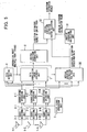
- Fig. 4 is a block diagram showing the configuration of forming sending directivity adaptively based on the result of the arrival direction estimation unit 8 according to Embodiment 1.
- the part that differs from Embodiment 1 is mainly described below.
- the operation until a direction estimate is obtained in the arrival direction estimation unit 8 based on a receiving signal by the array antenna 1 is the same as Embodiment 1.
- the operation of the arrival direction estimate unit 8 is performed as a different operation, that is,' 1) when all path arrival directions are estimated in the common direction ⁇ s and 2) multiple arrival direction estimates are output.
- a modulation unit 20 modulates sending data into a predetermined modulation format.
- the sending weight vector Ws uses a steering vector a ( ⁇ ) or the Chebyshev beam weight whose main beam faces toward the ⁇ s direction.
- W s a ⁇ s
- the sending weight vector Ws uses a value in which the steering vector a ( ⁇ ) is synthesized as shown in (Formula 13) or a value, in which multiple Chebyshev beam weights whose main beam faces to the estimation direction are synthesized.
- k 1 to Nd.
- Diffusion units 22-1 to N diffuse an output signal from the sending beam formation unit 21 using a diffusion code of a predetermined diffusion coefficient and output it to sending units 23-1 to N.
- the sending units 23-1 to N apply predetermined radio processing (D/A conversion and frequency up conversion) to the output of the diffusion units 22-1 to N, the signal is sent to a communication terminal via the antenna 1-1 to N.
- the estimate of the arrival direction estimation unit 8 can send a signal making the directivity of the array antenna 1 common to a path face toward the direction in which the composite power of multiple paths that arrive from an adjacent direction in the sending beam formation unit 21 when 1) all path arrival directions are estimated in the common direction ⁇ s.
- the angular extension of an arrival wave is considered to be equal or less than about 10°.
- this embodiment can estimate a direction in which the composite power of multiple paths is maximized based on the one-time angle sweep operation in the arrival direction estimation unit 8 without estimating the arrival direction per path and can reduce throughput and an arithmetic circuit scale.
- the estimate of the arrival direction estimation unit 8 can form a beam facing toward multiple estimation directions in the sending beam formation 21 when 2) the multiple' arrival direction estimates ⁇ k are output.
- the installation site of the array antenna 1 is as high as or below the heights of surrounding buildings, generally, the angular extension of an arrival wave increases and each of the multiple paths arrive with the angular extension.
- a directional beam can be formed on the path whose direction differs respectively and is provided with each spread.
- the communication terminal can receive a radio wave from each of the path directions and improves receiving characteristics by synthesizing and receiving the multiple paths effectively using the rake synthesis.
- this embodiment can estimate multiple path directions collectively by one-time arrival direction estimation processing. In this case, because multiple path arrival directions can be estimated from one angular spectrum, an amount of operation is reduced and its resultant device scale can be reduced.
- a sending weight is generated so that directivity can face toward each direction, but a directional beam may also be formed and sent only to the path direction of the maximum received power among the arrival directions of the estimated arrival path.
- the interference amount to another user can be suppressed and the communication capacity of the entire system is improved.
- a base station device used in a communication system that uses a CDMA system as a multiple system is described, but the same shall not be limited to this device.
- the present invention can also apply to the base station device used in a communication system that uses a multiple system of a TDMA system or an OFDM system.
- the aforementioned embodiment is described assuming that multiple antennas are arranged linearly at half-wave intervals of a carrier wave.
- the same shall not be limited to this embodiment.
- the present invention can apply to all the base station devices that have multiple antennas and form directivity.
- signals that arrive via each path were composed using the RAKE synthesis.
- the present invention may also use any synthesis method as long as the method can synthesize the signal that arrives via each path per antenna.
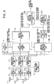
- Fig. 5 is a block diagram showing the configuration of a radio communication device that adds an arrival direction estimation unit 30 per path that estimates a path arrival direction in a different path receiving timing individually to the arrival direction estimation unit 8 described in Embodiment 1 and forms and receives a path receiving beam using one of these direction estimation results selectively.
- the operation of the arrival direction estimation unit 8 is the same as that of Embodiment 1, a description will be mainly made of the operation of a newly added arrival direction estimation unit 30 per path, an angular extension calculation unit 31 that calculates an angular extension based on the direction estimation result for every path and an arrival direction estimation system selection unit 32 that selects either of the estimation result of the arrival direction estimation unit 8 or that of the arrival direction estimation unit 30 per path based on the detection result of the angular extension.
- N is the number of antenna elements.
- the baseband signals 3-1 to N are input to each of the correlation operation units 4-1 to N in response to each signal respectively.
- the pilot signal generation unit 5 generates a known signal, (hereinafter referred to as pilot signal) embedded previously in a receiving signal.
- the correlation operation units 4-1 to N perform a mutual correlation operation with the pilot signal. For example, for a W-CDMA communication system, after inverse diffusion processing is performed with a scrambling code and a channelization code, a correlation operation with the pilot signal embedded in every frame is performed.
- the m-th correlation,operation unit 4-m is expressed as the m-th baseband signal 3-m (hereinafter referred to as Xm (t); here; t indicates a sample timing).
- the correlation operation shown in (Formula 1) calculates a pilot correlation value hm(p) of each sample timing by changing a sample timing p that starts the correlation operation from 1 to Ts only by the number of times that corresponds to the number of samples Ts within the time range in which a path search is performed. No is the number of over-samples for a symbol.
- * indicates a complex conjugate.
- the pilot signal correlation value hm(p) in the m-th antenna element 1-m whose sample timing p is the starting point of the correlation operation is obtained.
- the aforementioned operation is performed for the baseband signals 3-1 to N received by all the antenna elements 1-1 to N.
- the path detection unit 6 generates a delay profile based on the pilot signal correlation value hm(p) obtained by each of the correlation operation units 4-1 to N, selects high-level power paths of a predetermined number L, and outputs a selected path timing.
- the delay profile is generated using the methods of
- the arrival direction estimation per path unit 30 estimates an arrival direction for each of detected L paths. The operation is described below.
- the k-th arrival path receiving timing is pk
- an angular spectrum is calculated by varying 6in the arrival direction estimation evaluation function GK( ⁇ ) shown in (Formula 14) in a predetermined angle step ⁇ using the correlation vector Vk that includes the correlation information between the array antenna elements shown in (Formula 3).
- k an integer of 1 to L.
- a( ⁇ ) is a directional vector that depends on the element arrangement of the array antenna 1 and H indicates a vector conjugate transposed operator.
- the peak direction ⁇ k in of the angular spectrum of the obtained k-th path is the arrival direction estimate of the k-th path.
- G k ⁇
- the over-sample processing is performed for a symbol rate or chip rate
- the path detection unit 6 stores the phase information that results in.the spatial arrangement of the array antenna 1 to some extent even for the sample adjacent to the detected arrival path receiving timing, and the direction estimation accuracy can be increased by estimating the arrival direction to which this information is added.
- the arrival direction estimation evaluation function Gk( ⁇ ) at that time is shown in (Formula 15).
- a correlation matrix Uk is shown in (Formula 16) with the use of uk in (Formula 15).
- a correlation matrix of a predetermined sample number T adjacent before and after is added to the k-th arrival path receiving timing pk is calculated and the correlation vector of the (2T + 1) is added per path.
- the total number of sample timings (2T + 1) per path is set above the number of antenna elements N. Accordingly, the number of ranks of a correlation matrix can reach the full rank.
- the high resolution arrival direction estimation algorithm such as the MUSIC method and the ESPRIT method, and the arrival direction estimation algorithm using another beam former method, such as the Capon method, can be applied. Further, even if the arrival path power is low, such an effect that estimation accuracy is improved by adding a correlation vector in the adjacent timing is obtained.
- the direction estimation processing such as the MUSIC method, ESPRIT method, Capon method, and Fourier beam former method, may also be applied.
- a correlation can be suppressed and the rank of a correlation matrix Uk can be recovered.
- the processing that reduces an amount of calculation may also be added by calculating a correlation vector rk shown on the first line of the correlation matrix Uk, calculating an angular spectrum using the arrival direction estimation evaluation function expressed by the absolute value
- G k ⁇ a ( ⁇ ⁇ ) H
- the angular extension calculation unit 31 calculates an angular extension AS using the arrival direction estimate ⁇ k of the obtained L paths and the arrival direction estimation evaluation function value GK( ⁇ ) of the direction and using the formula shown in (Formula 17). ⁇ 0 is shown in (Formula 18).
- G k ⁇ k ⁇ k 1 L
- the arrival direction estimation system selection unit 32 selectively outputs a direction estimation result in the arrival direction estimation per path unit 30 when the angular extension AS exceeds a predetermined value based on the calculation value of the angular extension AS in the angular extension calculation unit 31.
- the arrival direction estimation system selection unit 32 selectively outputs a direction estimation result in the arrival direction estimation unit 8.
- the predetermined value used for the comparison with the angular extension AS also depends on the number of array elements, but, for example, uses about 5° to 10°.
- An arrival path direction can be estimated by the aforementioned operation.
- the directional receiving control for an arrival path is the same as the directional receiving operation for Embodiment 1 and the description is omitted.
- an arrival direction estimation system can be selected depending on the size of the angular extension obtained as a result of the arrival direction estimation per path. Accordingly, when the angular extension is smaller than the predetermined value, the path receiving beam formation unit 10 can receive a signal by making the directivity of the array antenna 1 common to a path facing toward the direction in which the composite power of the multiple paths that arrive from an adjacent direction is maximized, based on the estimation of the arrival direction estimation unit 8. Accordingly, even if the received power for every path is low, the average arrival direction of the multiple paths that arrive with an angular extension can be estimated with accuracy even for a fading fluctuation and communication can be performed with stable quality.
- the arrival direction can be estimated per path with the direction estimation accuracy that responds to the received power of the arrival path.
- the size of the angular extension depends on the installation site of the array antenna 1 and the height of a peripheral building.
- an arrival direction estimation system can be selected adaptively and communication can be performed with stable quality regardless of the installation site of the array antenna 1. Further, as compared with the operation in Embodiment 1, in this embodiment, because the arrival direction is estimated for every path, the communication can performed with more stable quality under the environment in which the angular extension is large.
- the angular extension AS calculated in the angular extension calculation unit 31 is calculated using the result of the arrival direction estimation per path unit 30, but the following two methods that differ from this can be applied.
- a base station device used in a communication system that uses a CDMA system as a multiple system is described, but the same shall not be limited to this device.
- the present invention can also apply to the base station device used in a communication system that uses a multiple system of a TDMA system or an OFDM system.
- the aforementioned embodiment is described assuming that multiple antennas are arranged linearly at half-wave length intervals of a carrier wave. The same shall not be limited to this embodiment, however.
- the present invention can apply to all the base station devices that have multiple antennas and form directivity.
- Fig. 6 is ia block diagram showing the configuration of a radio communication device in which a path detection unit 6b that detects multiple arrival path receiving timings exceeding the maximum number of fingers in which rake synthesis receiving is performed and an effective path selection unit 40 that selects a path within the maximum number of fingers in which rake synthesis receiving is performed from the received power when directivity is received in the arrival estimation direction for a path arrival direction estimation unit 30b in the detection path timing, is added to the configuration described in Embodiment 3.
- the part that differs from Embodiment 3 is mainly described below.
- N is the number of antenna elements.
- the baseband signals 3-1 to N are input to each of the correlation operation units 4-1 to N in response to each signal respectively.
- the pilot signal generation unit 5 generates a known signal (hereinafter referred to as a pilot signal) embedded previously in a receiving signal.
- the correlation operation units 4-1 to N perform a mutual correlation operation with the pilot signal. For example, for a W-CDMA communication system, after inverse diffusion processing is performed with a scrambling code and a channelization code, a correlation operation with the pilot signal embedded in every frame is performed.
- the m-th correlation operation unit 4-m is expressed as the m-th baseband signal 3-m (hereinafter referred to as Xm(t); here, t indicates a sample timing).
- the correlation operation shown in (Formula 1) calculates a pilot correlation value hm (p) of each sample timing by changing a sample timing p that starts the correlation operation from 1 to Ts only by the number of times that corresponds to the number of samples Ts within the time range in which a path search is performed. No is the number of over-samples for a symbol.
- * indicates a complex conjugate.
- the pilot signal correlation value hm(p) in the m-th antenna element, 1-m whose sample timing p is the starting point of the correlation operation is obtained.
- the aforementioned operation is performed for the baseband signals 3-1 to N received by all the antenna elements 1-1 to N.
- the path detection unit 6b generates a delay profile based on the pilot signal correlation value hm(p) obtained in each of the cooperation units 4-1 to N, selects multiple high-level power paths of the predetermined number L in which rake synthesis is received, and outputs the selected path timings.
- the delay profile is generated using the method of 1) composing the absolute value or square of the pilot signal correlation value hm(p) obtained in each of the antenna elements 1-1 to N or 2) generating multiple delay profiles of the same timing by the weight on which a directional beam is formed, adding both and obtaining the absolute value or square, and moreover multiple weights of different directivity, and then power-adding them.
- the path arrival direction estimation unit 30b estimates an arrival direction for each of detected L paths. The operation is described below.
- the k-th arrival path receiving timing is pk
- an angular spectrum is calculated by varying ⁇ in the arrival direction estimation evaluation function GK( ⁇ ) shown in (Formula 14) in a predetermined angle step ⁇ using the correlation vector Vk that includes the correlation information between the array antenna elements shown in (Formula 3).
- k an integer of 1 to L.
- a( ⁇ ) is a directional vector that depends on the element arrangement of the array antenna 1 and H indicates a vector conjugate transposed operator.
- the peak direction ⁇ k in of the angular spectrum of the obtained k-th path is the arrival direction estimate of the k-th path.
- the received power Hk when the directional receiving is performed is shown in (Formula 19).
- An angular extension calculation unit 31b calculates Q path arrival direction estimates ⁇ k in the maximum number of fingers in which rake synthesis receiving is performed and the angular extension AS using the received power Hk obtained when the directional beam of the direction is made to face and using the formula shown in (Formula 20) from the effective path selection result of the effective path selection unit 40.
- An arrival direction estimation system selection unit 32b selectively outputs a direction estimation result in the effective path selection unit 40 when the angular extension AS exceeds a predetermined value based on the calculation value of the angular extension AS in the angular extension calculation unit 31b.
- the direction estimation result in the arrival direction estimation unit 8 is output selectively.
- the predetermined value used for the comparison with the angular extension also depends on the number of array elements, but, for example, uses about 5° to 10°.
- An arrival path direction can be estimated by the aforementioned operation.
- the directional receiving control for an arrival path is the same as the directional receiving operation for embodiment 1 and the description is omitted.
- the arrival direction per path of the number that exceeds the maximum number of fingers in which rake receiving is performed can be estimated by detecting the arrival path receiving timing that exceeds the maximum number of fingers in the path detection unit 6b. Accordingly, since an effective path in the maximum number of fingers in which the rake receiving is performed can be selected based on the path power that can be received when a directional beam is made to face toward the arrival direction per path, the effective path selection performance, that is, the path search performance can be increased. Then receiving performance can be increased by the path search performance.
- the angular extension AS is calculated in the angular extension calculation unit 31b using the result of the effective path selection unit 40, the following two methods that differ from this can be applied.
- the path detection unit 6 after the output of each of the correlation operation units 4-1 to N is made average over a predetermined count (predetermined frame period), multiple arrival path receiving timings may also be detected by generating a delay profile. In this case, the follow-up for a path fluctuation deteriorates, but the path detection accuracy can be increased and the robustness of the path detection operation can be improved.
- a base station device used in a communication system that uses a CDMA system as a multiple system is described, but the same shall not be limited to this device.
- the present invention can also apply to the base station device used in a communication system that uses a multiple system of a TDMA system or an OFDM system.
- the aforementioned embodiment is described assuming that multiple antennas are arranged linearly at half-wave length intervals of a carrier wave. The same shall not be limited to this embodiment, however.
- the present invention can apply to all the base station devices that have multiple antennas and form directivity.
Claims (8)
- Funkkommunikationsvorrichtung, die umfasst:eine Array-Antenne (1-1, ..., 1-N), die aus mehreren Antennenelementen besteht;mehrere Funkempfangseinheiten (2-1, ...,.2-N), die so eingerichtet sind, dass sie Frequenzumwandlung von Hochfrequenzsignalen durchführen, die durch jedes der Antennenelemente der Array-Antenne empfangen werden, die Signale mit phasengleichen (I) und phasenversetzten (Q) Komponenten orthogonal erfassen und Basisbandsignale ausgeben, die aus I- und Q-Signalen bestehen;mehrere Korrelationsoperations-Einheiten (4-1, ..., 4-N), die so eingerichtet sind, dass sie wechselseitige Korrelationsoperationen mit vorgegebenen Signalen für jedes der Basisbandsignale durchführen;eine Pfaderfassungseinheit (6), die so eingerichtet ist, dass sie mehrere Ankunftspfad-Empfangszeiten erfasst, indem sie ein Verzögerungsprofil auf Basis des Ausgangs jeder der Korrelations-Operationseinheiten erzeugt;eine Pfadkorrelationswert-Syntheseeinheit (7), die so eingerichtet ist, dass sie Pfadkorrelationswerte synthetisiert, die in den mehreren Korrelations-Operationseinheiten zu den erfassten mehreren Ankunftspfad-Empfangszeiten berechnet werden; undeine Ankunftsrichtungs-Schätzeinheit (8), die so eingerichtet ist, dass sie die durchschnittliche Ankunftsrichtung mehrerer Pfade unter Verwendung des Ausgangs der Pfadkorrelationswert-Syntheseeinheit schätzt;gekennzeichnet durch
eine Einheit (30) zum Schätzen der Ankunftsrichtung nach Pfad, die so eingerichtet ist, dass sie eine Ankunftsrichtung für jede der mehreren Ankunftspfad-Empfangszeiten aus dem in den mehreren Korrelations-Operationseinheiten zu den mehreren Ankunftspfad-Empfangszeiten berechneten Korrelations-Operationswert schätzt;
eine Vvinkeiausdehnungs-Berechnungseinheit (31), die so eingerichtet ist, dass sie eine Winkelausdehnung eines gesamten Ankunftspfades anhand eines Ergebnisses der Ankunftsrichtungs-Schätzung nach Pfad in der Einheit (30) zum Schätzen der Ankunftsrichtung nach Pfad berechnet; und
eine Einheit (32) zum Auswählen des Ankunftsrichtungs-Schätzsystems, die so eingerichtet ist, dass sie auf Basis einer Differenz zwischen einem Ausgangswert und einem vorgegebenen Wert der Winkelausdehnungs-Schätzeinheit entweder das Richtungs-Schätzergebnis der Ankunftsrichtungs-Schätzeinheit, die durchschnittliche Ankunftsrichtung mehrerer Pfade schätzt, oder das Richtungs-Schätzergebnis für jede der durch die Einheit zum Schätzen der Ankunftsrichtung nach Pfad geschätzten mehreren Ankunftspfad-Empfangszeiten auswählt und ausgibt. - Funkkommunikationsvorrichtung nach Anspruch 1, wobei die Winkelausdehnungs-Berechnungseinheit (31) des Weiteren so eingerichtet ist, dass sie die Winkelausdehnung des gesamten Ankunftspfades anhand eines Verhältnisses eines maximalen Eigenwertes einer in der Pfadkorrelationswert-Syntheseeinheit erzeugten Korrelationsmatrix zu einem zweitgrößten Eigenwert berechnet.
- Funkkommunikationsvorrichtung nach Anspruch 1 oder 2, wobei
die Winkelausdehnungs-Berechnungseinheit (31) des Weiteren so eingerichtet ist, dass sie die Winkelausdehnung des gesamten Ankunftsweges anhand der Spitzenposition berechnet, die in dem Winkelspektrum auftritt, das in der Ankunftsrichtungs-Schätzeinheit erzeugt wird. - Funkkommunikationsvorrichtung nach einem der Ansprüche 1 bis 3, die des Weiteren umfasst:eine Einheit (40) zum Auswählen eines effektiven Pfades, die so eingerichtet ist, dass sie einen Pfad mit einer maximalen Anzahl von Fingern auswählt, in denen Rechen-Synthese (rake synthesis) anhand von Empfangsleistung durchgeführt wird, wenn gerichteter Empfang in der Pfad-Ankunftsrichtung nach Pfad durchgeführt wird, und wobeidie Pfaderfassungseinheit (6) die mehreren Ankunftspfad-Empfangszeiten erfasst, die die maximale Anzahl von Fingern übersteigen, in denen Rechen-Synthese empfangen wird;die Einheit (30b) zum Schätzen der Ankunftsrichtung nach Pfad die Ankunftsrichtung für jede der mehreren Ankunftspfad-Empfangszeiten anhand des in den mehreren Korrelations-Operationseinheiten (4-1, ..., 4-N) zu den mehreren Ankunftspfad-Empfangszeiten berechneten Korrelations-Operationswertes schätzt; unddie Winkelausdehnungs-Berechnungseinheit (31 b) und die Einheit (32b) zum Auswählen des Ankunftsrichtungs-Schätzsystems als Eingang anstelle des Ausgangs der Einheit zum Schätzen der Ankunftsrichtung nach Pfad den Ausgang der Einheit zum Auswählen des effektiven Pfades angeben.
- Funkkommunikationsvorrichtung nach einem der Ansprüche 1 bis 4,
wobei die Einheit (30) zum Schätzen der Ankunftsrichtung nach Pfad des Weiteren die Ankunftsrichtung nach Pfad unter Verwendung des in der Korrelations-Operationseinheit (4-1, ..., 4-N) zu einer Abtastzeit unmittelbar vor und nach der Ankunftspfad-Empfangszeit zusätzlich zu der Ankunftspfad-Empfangszeit berechneten Korrelations-Operationswertes schätzt. - Funkkommunikationsvorrichtung nach einem der Ansprüche 1 - 5, wobei die Einheit (30) zum Schätzen der Ankunftsrichtung nach Pfad des Weiteren die Ankunftsrichtung nach Pfad durch Berechnen einer Korrelationsmatrix unter Verwendung des in der Korrelations-Operationseinheit (4-1, ..., 4-N) zu der Abtastzeit unmittelbar vor und nach der Ankunftspfad-Empfangszeit zusätzlich zu der Ankunftspfad-Empfangszeit berechneten Korrelations-Operationswertes-schätzt.
- Funkkommunikationsvorrichtung nach Anspruch 6, wobei die Einheit (30) zum Schätzen der Ankunftsrichtung nach Pfad die Korrelationsmatrix unter Verwendung des in der Korrelations-Operationseinheit (4-1, ..., 4-N) zu der Abtastzeit unmittelbar vor und nach der Ankunftspfad-Empfangszeit zusätzlich zu der Ankunftspfad-Empfangszeit berechneten Korrelations-Operationswertes berechnet und die Ankunftsrichtung nach Pfad unter Verwendung der Korrelationsmatrix schätzt, auf die räumliche Glättungsverarbeitung angewendet wird.
- Verfahren zum Schätzen der Ankunftszeit, mit dem die durchschnittliche Ankunftsrichtung mehrerer Pfade geschätzt wird, wobei es die folgenden Schritte umfasst:Empfangen mehrerer I/Q-Basisbandsignale, die ermittelt werden, indem Frequenzumwandlung mehrerer Signale durchgeführt wird, die mit einer Array-Antenne empfangen werden, die aus mehreren Antennenelementen besteht, und orthogonales Erfassen jeweils mit mehreren Funkempfangseinheiten;Berechnen von Korrelationsoperations-Werten mit bekannten Signalen zu jeder von mehreren erfassten Ankunftspfad-Empfangszeiten;Ermitteln eines Winkelspektrums unter Verwendung eines Pfadkorrelationswert-Synthesesignals, indem die berechneten mehreren Korrelations-Operationswerte synthetisiert werden; undSchätzen einer durchschnittlichen Ankunftsrichtung mehrerer Pfade unter Verwendung des Pfadkorrelationswert-Synthesesignals in einer Ankunftsrichtungs-Schätzeinheit, gekennzeichnet durchSchätzen einer Ankunftsrichtung für jede der mehreren Ankunftspfad-Empfangszeiten anhand des zu den mehreren Ankunftspfad-Empfangszeiten berechneten Korrelations-Operationswertes;Berechnen einer Winkelausdehnung des gesamten Ankunftspfades; undAuswählen und Ausgeben entweder des Richtungs-Schätzergebnisses der Ankunftsrichtungs-Schätzeinheit, die die durchschnittliche Ankunftsrichtung mehrerer Pfade schätzt, oder des Richtungs-Schätzergebnisses für jede der mehreren Ankunftspfad-Empfangszeiten auf Basis einer Differenz zwischen einem Ausgangswert und einem vorgegebenen Wert der Winkel-Ausdehnungsberechnung.
Priority Applications (1)
| Application Number | Priority Date | Filing Date | Title |
|---|---|---|---|
| EP07112913A EP1843487B1 (de) | 2002-05-07 | 2003-05-07 | Funkkommunikationsvorrichtung und Verfahren zur Schätzung der Wellenankunftsrichtung |
Applications Claiming Priority (4)
| Application Number | Priority Date | Filing Date | Title |
|---|---|---|---|
| JP2002132069 | 2002-05-07 | ||
| JP2002132069 | 2002-05-07 | ||
| JP2002220302A JP3895228B2 (ja) | 2002-05-07 | 2002-07-29 | 無線通信装置および到来方向推定方法 |
| JP2002220302 | 2002-07-29 |
Related Child Applications (1)
| Application Number | Title | Priority Date | Filing Date |
|---|---|---|---|
| EP07112913A Division EP1843487B1 (de) | 2002-05-07 | 2003-05-07 | Funkkommunikationsvorrichtung und Verfahren zur Schätzung der Wellenankunftsrichtung |
Publications (3)
| Publication Number | Publication Date |
|---|---|
| EP1361679A2 EP1361679A2 (de) | 2003-11-12 |
| EP1361679A3 EP1361679A3 (de) | 2005-04-13 |
| EP1361679B1 true EP1361679B1 (de) | 2008-05-28 |
Family
ID=29253670
Family Applications (2)
| Application Number | Title | Priority Date | Filing Date |
|---|---|---|---|
| EP07112913A Expired - Fee Related EP1843487B1 (de) | 2002-05-07 | 2003-05-07 | Funkkommunikationsvorrichtung und Verfahren zur Schätzung der Wellenankunftsrichtung |
| EP03010293A Expired - Fee Related EP1361679B1 (de) | 2002-05-07 | 2003-05-07 | Funkkommunikationsvorrichtung und Verfahren zum Schätzen der Einfallsrichtung |
Family Applications Before (1)
| Application Number | Title | Priority Date | Filing Date |
|---|---|---|---|
| EP07112913A Expired - Fee Related EP1843487B1 (de) | 2002-05-07 | 2003-05-07 | Funkkommunikationsvorrichtung und Verfahren zur Schätzung der Wellenankunftsrichtung |
Country Status (5)
| Country | Link |
|---|---|
| US (4) | US7263083B2 (de) |
| EP (2) | EP1843487B1 (de) |
| JP (1) | JP3895228B2 (de) |
| CN (2) | CN100583710C (de) |
| DE (1) | DE60321266D1 (de) |
Families Citing this family (76)
| Publication number | Priority date | Publication date | Assignee | Title |
|---|---|---|---|---|
| JP3856126B2 (ja) * | 2002-05-21 | 2006-12-13 | 日本電気株式会社 | パスタイミング検出方法、パスタイミング検出装置及び適応アレーアンテナシステム |
| US8005128B1 (en) * | 2003-09-23 | 2011-08-23 | Rambus Inc. | Methods for estimation and interference cancellation for signal processing |
| JP4309110B2 (ja) * | 2002-09-27 | 2009-08-05 | パナソニック株式会社 | 適応アンテナ無線通信装置 |
| US7065144B2 (en) | 2003-08-27 | 2006-06-20 | Qualcomm Incorporated | Frequency-independent spatial processing for wideband MISO and MIMO systems |
| US8472473B2 (en) * | 2003-10-15 | 2013-06-25 | Qualcomm Incorporated | Wireless LAN protocol stack |
| US8462817B2 (en) | 2003-10-15 | 2013-06-11 | Qualcomm Incorporated | Method, apparatus, and system for multiplexing protocol data units |
| US8842657B2 (en) | 2003-10-15 | 2014-09-23 | Qualcomm Incorporated | High speed media access control with legacy system interoperability |
| US8284752B2 (en) | 2003-10-15 | 2012-10-09 | Qualcomm Incorporated | Method, apparatus, and system for medium access control |
| US8233462B2 (en) | 2003-10-15 | 2012-07-31 | Qualcomm Incorporated | High speed media access control and direct link protocol |
| US9226308B2 (en) | 2003-10-15 | 2015-12-29 | Qualcomm Incorporated | Method, apparatus, and system for medium access control |
| US8483105B2 (en) | 2003-10-15 | 2013-07-09 | Qualcomm Incorporated | High speed media access control |
| KR100611170B1 (ko) * | 2003-11-11 | 2006-08-10 | 가부시키가이샤 엔티티 도코모 | 수신 장치 및 수신 타이밍 검출 방법 |
| JP2005191997A (ja) * | 2003-12-26 | 2005-07-14 | Sanyo Electric Co Ltd | 受信方法および装置 |
| US7818018B2 (en) | 2004-01-29 | 2010-10-19 | Qualcomm Incorporated | Distributed hierarchical scheduling in an AD hoc network |
| US8903440B2 (en) | 2004-01-29 | 2014-12-02 | Qualcomm Incorporated | Distributed hierarchical scheduling in an ad hoc network |
| US8315271B2 (en) | 2004-03-26 | 2012-11-20 | Qualcomm Incorporated | Method and apparatus for an ad-hoc wireless communications system |
| JP4329594B2 (ja) * | 2004-03-30 | 2009-09-09 | 富士通株式会社 | アレーアンテナ無線通信装置およびそのパスタイミング検出方法 |
| US7564814B2 (en) | 2004-05-07 | 2009-07-21 | Qualcomm, Incorporated | Transmission mode and rate selection for a wireless communication system |
| US8401018B2 (en) | 2004-06-02 | 2013-03-19 | Qualcomm Incorporated | Method and apparatus for scheduling in a wireless network |
| JP2006013786A (ja) * | 2004-06-24 | 2006-01-12 | Ntt Docomo Inc | 適応アンテナアレー受信装置及びその方法 |
| JP4389704B2 (ja) * | 2004-07-16 | 2009-12-24 | 日本電気株式会社 | Cdma受信装置、およびcdma受信装置における同期タイミング検出方法 |
| JP3895344B2 (ja) * | 2004-09-09 | 2007-03-22 | 株式会社東芝 | 受信装置 |
| US7882412B2 (en) * | 2004-10-05 | 2011-02-01 | Sanjiv Nanda | Enhanced block acknowledgement |
| CN100544231C (zh) * | 2005-06-08 | 2009-09-23 | 中兴通讯股份有限公司 | 基于软件无线电的智能天线实现方法及智能天线实现系统 |
| JP4583265B2 (ja) * | 2005-07-21 | 2010-11-17 | 富士通株式会社 | 無線通信装置及び無線通信方法 |
| US8600336B2 (en) | 2005-09-12 | 2013-12-03 | Qualcomm Incorporated | Scheduling with reverse direction grant in wireless communication systems |
| US8102830B2 (en) * | 2005-12-16 | 2012-01-24 | Samsung Electronics Co., Ltd. | MIMO radio communication apparatus and method |
| JP4757629B2 (ja) | 2005-12-28 | 2011-08-24 | 株式会社デンソーアイティーラボラトリ | 到来方位推定装置 |
| JP4425880B2 (ja) * | 2006-01-18 | 2010-03-03 | 株式会社エヌ・ティ・ティ・ドコモ | 通信装置、移動局及び方法 |
| KR100765296B1 (ko) * | 2006-01-31 | 2007-10-09 | 다진정보기술 주식회사 | 인슐레이터 부착장치 |
| JP5062804B2 (ja) * | 2006-03-30 | 2012-10-31 | 株式会社豊田中央研究所 | 到来波推定方法および装置 |
| JP4593508B2 (ja) * | 2006-03-31 | 2010-12-08 | Kddi株式会社 | 空間角度広がり推定方法および受信装置 |
| JP4633667B2 (ja) * | 2006-03-31 | 2011-02-16 | Kddi株式会社 | アレーアンテナ送信装置 |
| JP2008011285A (ja) * | 2006-06-30 | 2008-01-17 | Fujitsu Ltd | 送信電力制御装置及び送信電力制御方法 |
| JP5186748B2 (ja) * | 2006-09-29 | 2013-04-24 | 富士通株式会社 | 無線通信装置および無線通信方法 |
| JP4910651B2 (ja) * | 2006-11-16 | 2012-04-04 | 株式会社デンソー | 通信統合レーダ装置、通信統合レーダシステム |
| JP5154119B2 (ja) * | 2007-03-26 | 2013-02-27 | テレフオンアクチーボラゲット エル エム エリクソン(パブル) | プロセッサ |
| EP1976136A1 (de) * | 2007-03-29 | 2008-10-01 | Telefonaktiebolaget LM Ericsson (publ) | Rake-Empfänger und Verfahren zur Anordnung der Finger in einem Rake-Empfänger |
| CN101022287A (zh) * | 2007-04-09 | 2007-08-22 | 互芯集成电路(北京)有限公司 | 码分多址通信系统中的多径检测方法及接收机 |
| JP5134380B2 (ja) * | 2008-01-15 | 2013-01-30 | 京セラ株式会社 | 通信方法およびそれを利用した無線装置 |
| KR101040256B1 (ko) | 2008-11-14 | 2011-06-09 | 엘아이지넥스원 주식회사 | 방탐 정확도가 향상된 신호 방향 탐지 시스템 및 그 방법 |
| CN101783697B (zh) * | 2009-01-15 | 2013-01-02 | 北京信威通信技术股份有限公司 | 一种ofdma多天线系统的发射分集方法 |
| EP2438648A4 (de) * | 2009-02-19 | 2014-06-25 | Polyvalor Ltd Partnership | System zur steuerung eines strahlungsmusters einer richtantenne |
| US20100304744A1 (en) * | 2009-05-29 | 2010-12-02 | Qualcomm Incorporated | Method and apparatus for performing searches with multiple receive diversity (rxd) search modes |
| WO2010143432A1 (ja) | 2009-06-12 | 2010-12-16 | パナソニック株式会社 | 無線通信装置及び無線通信方法 |
| CA2765746A1 (en) * | 2009-06-19 | 2010-12-23 | Cohda Wireless Pty Ltd | Environment estimation in a wireless communication system |
| JP2011013056A (ja) * | 2009-07-01 | 2011-01-20 | Toyota Central R&D Labs Inc | レーダ装置 |
| US8306483B2 (en) * | 2009-12-24 | 2012-11-06 | Intel Corporation | Method and system for improving wireless link robustness using spatial diversity |
| US8442468B2 (en) | 2010-04-12 | 2013-05-14 | Telefonaktiebolaget L M Ericsson (Publ) | Omni-directional sensing of radio spectra |
| US8737944B2 (en) * | 2010-05-21 | 2014-05-27 | Kathrein-Werke Kg | Uplink calibration system without the need for a pilot signal |
| JP5628732B2 (ja) * | 2011-04-04 | 2014-11-19 | 富士通テン株式会社 | レーダ装置用の演算装置、レーダ装置、レーダ装置用の演算方法およびプログラム |
| US11835639B2 (en) | 2011-08-03 | 2023-12-05 | Qualcomm Technologies, Inc. | Partially synchronized multilateration or trilateration method and system for positional finding using RF |
| CN102662158B (zh) * | 2012-05-04 | 2013-08-14 | 电子科技大学 | 一种对传感器天线阵列接收信号的快速处理方法 |
| CN102694588B (zh) * | 2012-06-15 | 2014-12-03 | 华南师范大学 | 一种基于共轭扩展的波达方向估计方法 |
| EP2867691B1 (de) | 2012-06-29 | 2016-11-02 | Blinksight | Vorrichtung und verfahren zur ortung eines rfid-senders |
| US10863313B2 (en) | 2014-08-01 | 2020-12-08 | Polte Corporation | Network architecture and methods for location services |
| US10440512B2 (en) * | 2012-08-03 | 2019-10-08 | Polte Corporation | Angle of arrival (AOA) positioning method and system for positional finding and tracking objects using reduced attenuation RF technology |
| JP2014197805A (ja) * | 2013-03-29 | 2014-10-16 | 日立オートモティブシステムズ株式会社 | 電池システム |
| JP2015012568A (ja) | 2013-07-02 | 2015-01-19 | 三星電子株式会社Samsung Electronics Co.,Ltd. | 指向性制御装置、および指向性制御方法 |
| GB2533539A (en) * | 2013-10-02 | 2016-06-22 | Terabit Radios Inc | High throughput interference cancelling radio transceiver and antenna therefor |
| US20160248495A1 (en) * | 2013-11-29 | 2016-08-25 | Nec Corporation | Radio Communication Apparatus and Radio Communication Method |
| CN103760519B (zh) * | 2014-01-24 | 2016-02-03 | 深圳大学 | 高分辨率doa估计方法及系统 |
| CN103792528B (zh) * | 2014-02-11 | 2016-05-04 | 哈尔滨工程大学 | 一种基于对角减载的水声阵列Bartlett波束形成的方法 |
| CN103901421B (zh) * | 2014-03-24 | 2016-07-06 | 哈尔滨工程大学 | 基于对角减载的水声阵列smi-mvdr空间谱估计方法 |
| WO2016007138A1 (en) * | 2014-07-08 | 2016-01-14 | New York University | System, method and computer-readable medium for estimating direction of arrival of a signal incident on at least one antenna array |
| EP3241284B1 (de) * | 2014-12-30 | 2020-06-24 | Sony Corporation | Bestimmung von diversitätsmodi für mimo-systeme |
| ES2730731T3 (es) * | 2014-12-31 | 2019-11-12 | Huawei Tech Co Ltd | Dispositivo y método de ajuste de haz de antena de matriz |
| JP6211226B2 (ja) * | 2015-02-17 | 2017-10-11 | 三菱電機株式会社 | 受信装置及び受信方法 |
| DE112017001984T5 (de) * | 2016-04-12 | 2019-01-03 | Mitsubishi Electric Corporation | Empfangsvorrichtung und Empfangsverfahren sowie Programm und Aufzeichnungsmedium |
| CN106420688B (zh) * | 2016-10-08 | 2017-11-10 | 西北大学 | Idhp制备预防和治疗冠状动脉粥样硬化疾病药物的应用 |
| US10886980B2 (en) * | 2017-03-08 | 2021-01-05 | Mitsubishi Electric Corporation | Wireless communication apparatus and wireless communication method |
| CN110520749B (zh) * | 2017-05-10 | 2021-09-07 | 华为技术有限公司 | 估计无线信号到达时间的方法和设备 |
| US11255945B2 (en) | 2018-03-27 | 2022-02-22 | Polte Corporation | Multi-path mitigation in tracking objects using compressed RF data |
| US10935624B2 (en) * | 2018-03-29 | 2021-03-02 | L3 Technologies, Inc. | Efficiently measuring phase differences in an angle of arrival system |
| US11460531B2 (en) * | 2020-02-27 | 2022-10-04 | The Boeing Company | Systems and methods for enhanced direction of arrival detection and calculation |
| CN112311482B (zh) * | 2020-11-26 | 2023-06-09 | Oppo(重庆)智能科技有限公司 | 定位方法、装置、系统、接收节点、发射节点和存储介质 |
Family Cites Families (35)
| Publication number | Priority date | Publication date | Assignee | Title |
|---|---|---|---|---|
| JPH03194483A (ja) | 1989-12-22 | 1991-08-26 | Ono Sokki Co Ltd | 非整相型方位検出装置 |
| US6018317A (en) * | 1995-06-02 | 2000-01-25 | Trw Inc. | Cochannel signal processing system |
| GB2318705B (en) | 1996-10-22 | 2001-05-02 | Motorola Ltd | Mobile telephone systems |
| BR9812816A (pt) * | 1997-09-15 | 2000-08-08 | Adaptive Telecom Inc | Processos para comunicação sem fio, e para eficientemente determinar na estação base um canal espacial da unidade móvel em um sistema de comunicação sem fio, e, estação base de cdma |
| JP3716398B2 (ja) * | 1998-03-05 | 2005-11-16 | 富士通株式会社 | アレーアンテナによる到来方向推定方法及び該方法を用いたds−cdma受信装置 |
| JP2967571B1 (ja) * | 1998-05-01 | 1999-10-25 | 日本電気株式会社 | Cdmaマルチユーザ受信装置と通信システム |
| JP2000059278A (ja) * | 1998-08-03 | 2000-02-25 | Matsushita Electric Ind Co Ltd | 無線通信装置 |
| JP3251261B2 (ja) * | 1999-04-21 | 2002-01-28 | エヌイーシーモバイリング株式会社 | Cdma受信装置 |
| JP3322246B2 (ja) * | 1999-07-21 | 2002-09-09 | 日本電気株式会社 | パスサーチ装置および方法 |
| JP4303373B2 (ja) * | 1999-09-14 | 2009-07-29 | 株式会社日立コミュニケーションテクノロジー | 無線基地局装置 |
| EP1088640B1 (de) * | 1999-09-29 | 2002-07-24 | Millipore S.A.S. | Verfahren zum Dichten eines Filterelements in einer Filterkassette und so hergestellte Filtervorrichtungen |
| JP2006041562A (ja) * | 1999-11-18 | 2006-02-09 | Matsushita Electric Ind Co Ltd | 基地局装置及び無線受信方法 |
| JP2001196835A (ja) | 2000-01-17 | 2001-07-19 | Matsushita Electric Ind Co Ltd | 到来方向推定方法及び無線受信装置 |
| WO2001067627A1 (fr) * | 2000-03-06 | 2001-09-13 | Fujitsu Limited | Recepteur amcr et detecteur d'un tel recepteur |
| US6369756B1 (en) | 2000-03-28 | 2002-04-09 | Nokia Networks Oy | Method and apparatus for optimizing the usage of an antenna array beamforming technique |
| JP3874991B2 (ja) | 2000-04-21 | 2007-01-31 | 株式会社東芝 | 無線基地局およびそのフレーム構成方法 |
| JP4509297B2 (ja) * | 2000-04-26 | 2010-07-21 | 三菱電機株式会社 | スペクトル拡散受信装置 |
| JP4392109B2 (ja) * | 2000-05-12 | 2009-12-24 | パナソニック株式会社 | 到来方向推定装置 |
| JP3424659B2 (ja) * | 2000-06-02 | 2003-07-07 | 日本電気株式会社 | マルチビーム受信装置 |
| JP3595493B2 (ja) * | 2000-07-10 | 2004-12-02 | 三菱電機株式会社 | 無線受信装置 |
| TW513873B (en) * | 2000-07-27 | 2002-12-11 | Sanyo Electric Co | Radio equipment capable of real time change of antenna directivity and Doppler frequency estimating circuit used for the radio equipment |
| US7298774B2 (en) * | 2000-08-25 | 2007-11-20 | Sanyo Electric Co., Ltd. | Adaptive array device, adaptive array method and program |
| FR2813465B1 (fr) * | 2000-08-29 | 2005-04-08 | Mitsubishi Electric Inf Tech | Methode d'estimation conjointe de canal et de direction d'arrivee |
| JP3591581B2 (ja) * | 2000-08-30 | 2004-11-24 | 日本電気株式会社 | 適応アンテナ受信装置 |
| JP4087549B2 (ja) | 2000-09-06 | 2008-05-21 | 富士通株式会社 | アレーアンテナ無線通信装置 |
| JP2002084217A (ja) | 2000-09-08 | 2002-03-22 | Matsushita Electric Ind Co Ltd | 基地局装置および到来方向推定方法 |
| KR100383669B1 (ko) * | 2000-10-12 | 2003-05-14 | 한국전자통신연구원 | 배열 안테나를 이용하는 코드분할다중접속 기지국시스템의 동기 획득장치 및 방법 |
| JP2002135185A (ja) | 2000-10-19 | 2002-05-10 | Hitachi Kokusai Electric Inc | 受信機 |
| JP2002176384A (ja) * | 2000-12-07 | 2002-06-21 | Hitachi Kokusai Electric Inc | 受信機 |
| EP1387180A1 (de) | 2000-12-12 | 2004-02-04 | Matsushita Electric Industrial Co., Ltd. | Funkempfangspeilantennengerät und Sender-Empfänger mit variabler Richtcharakteristik |
| JP2002237766A (ja) | 2001-02-08 | 2002-08-23 | Nec Corp | 適応アンテナ受信装置 |
| JP3813490B2 (ja) * | 2001-10-30 | 2006-08-23 | 富士通株式会社 | スペクトラム拡散レイク受信機 |
| RU2232485C2 (ru) * | 2001-11-27 | 2004-07-10 | Корпорация "Самсунг Электроникс" | Способ формирования диаграммы направленности антенны и устройство для его реализации |
| JP2006258529A (ja) * | 2005-03-16 | 2006-09-28 | Fujitsu Ten Ltd | 電波到来方向推定装置及び方法 |
| JP4722132B2 (ja) * | 2005-07-11 | 2011-07-13 | 富士通株式会社 | 到来波数推定方法、到来波数推定装置及び無線装置 |
-
2002
- 2002-07-29 JP JP2002220302A patent/JP3895228B2/ja not_active Expired - Fee Related
-
2003
- 2003-05-07 CN CN03130719A patent/CN100583710C/zh not_active Expired - Fee Related
- 2003-05-07 EP EP07112913A patent/EP1843487B1/de not_active Expired - Fee Related
- 2003-05-07 CN CN200910225366.8A patent/CN101729092B/zh not_active Expired - Fee Related
- 2003-05-07 DE DE60321266T patent/DE60321266D1/de not_active Expired - Lifetime
- 2003-05-07 EP EP03010293A patent/EP1361679B1/de not_active Expired - Fee Related
- 2003-05-07 US US10/430,397 patent/US7263083B2/en active Active
-
2007
- 2007-08-02 US US11/833,037 patent/US7860064B2/en not_active Expired - Fee Related
-
2010
- 2010-12-27 US US12/979,305 patent/US8520641B2/en not_active Expired - Fee Related
- 2010-12-27 US US12/979,318 patent/US8532064B2/en not_active Expired - Fee Related
Also Published As
| Publication number | Publication date |
|---|---|
| EP1361679A3 (de) | 2005-04-13 |
| US20110090813A1 (en) | 2011-04-21 |
| DE60321266D1 (de) | 2008-07-10 |
| US7860064B2 (en) | 2010-12-28 |
| JP2004032656A (ja) | 2004-01-29 |
| US8520641B2 (en) | 2013-08-27 |
| EP1361679A2 (de) | 2003-11-12 |
| US8532064B2 (en) | 2013-09-10 |
| EP1843487A1 (de) | 2007-10-10 |
| US20110090120A1 (en) | 2011-04-21 |
| US20070273584A1 (en) | 2007-11-29 |
| JP3895228B2 (ja) | 2007-03-22 |
| CN1457164A (zh) | 2003-11-19 |
| EP1843487B1 (de) | 2011-07-06 |
| CN101729092B (zh) | 2015-06-10 |
| CN100583710C (zh) | 2010-01-20 |
| CN101729092A (zh) | 2010-06-09 |
| US20030210670A1 (en) | 2003-11-13 |
| US7263083B2 (en) | 2007-08-28 |
Similar Documents
| Publication | Publication Date | Title |
|---|---|---|
| EP1361679B1 (de) | Funkkommunikationsvorrichtung und Verfahren zum Schätzen der Einfallsrichtung | |
| US7088956B2 (en) | Path search circuit, radio receiver and radio transmitter, utilizing a directional beam | |
| US7117016B2 (en) | Adaptive antenna base station apparatus | |
| US6879624B2 (en) | Adaptive antenna receiver | |
| US7333056B2 (en) | Adaptive antenna radio communication device | |
| US7039135B2 (en) | Interference reduction using low complexity antenna array | |
| JP3738705B2 (ja) | 適応アンテナ装置 | |
| US20030069047A1 (en) | Adaptive array antenna directivity control system | |
| EP1575187B1 (de) | Radiogerät zur echtzeitlichen Antennarichtwirkung Steuerung und Gerät zum Dopplerfrequenz Ausrechnen | |
| US6771984B1 (en) | Base station device and radio communication method | |
| CN101268632B (zh) | 到达方向估算方法及其装置 | |
| KR100679435B1 (ko) | 초기단계부터 지향성 빔의 우수한 수신품질을 갖는 적응형안테나 수신 장치 | |
| JP3423275B2 (ja) | ドップラー周波数推定回路およびドップラー周波数推定回路を用いた無線装置 | |
| JP4430060B2 (ja) | 無線通信装置及び方法 | |
| US7095984B2 (en) | Base station apparatus and direction-of-arrival estimating method |
Legal Events
| Date | Code | Title | Description |
|---|---|---|---|
| PUAI | Public reference made under article 153(3) epc to a published international application that has entered the european phase |
Free format text: ORIGINAL CODE: 0009012 |
|
| AK | Designated contracting states |
Kind code of ref document: A2 Designated state(s): AT BE BG CH CY CZ DE DK EE ES FI FR GB GR HU IE IT LI LU MC NL PT RO SE SI SK TR |
|
| AX | Request for extension of the european patent |
Extension state: AL LT LV MK |
|
| RIN1 | Information on inventor provided before grant (corrected) |
Inventor name: KISIGAMI, TAKAAKI Inventor name: KEIJI,TAKAKUSAKI Inventor name: MIYAMOTO, SHOJI Inventor name: FUKAGAWA, TAKASHI Inventor name: YUDA, YASUAKI |
|
| PUAL | Search report despatched |
Free format text: ORIGINAL CODE: 0009013 |
|
| AK | Designated contracting states |
Kind code of ref document: A3 Designated state(s): AT BE BG CH CY CZ DE DK EE ES FI FR GB GR HU IE IT LI LU MC NL PT RO SE SI SK TR |
|
| AX | Request for extension of the european patent |
Extension state: AL LT LV MK |
|
| 17P | Request for examination filed |
Effective date: 20050630 |
|
| AKX | Designation fees paid |
Designated state(s): DE FR GB |
|
| 17Q | First examination report despatched |
Effective date: 20051121 |
|
| GRAP | Despatch of communication of intention to grant a patent |
Free format text: ORIGINAL CODE: EPIDOSNIGR1 |
|
| RIN1 | Information on inventor provided before grant (corrected) |
Inventor name: KEIJI,TAKAKUSAKI Inventor name: FUKAGAWA, TAKASHI Inventor name: KISIGAMI, TAKAAKI Inventor name: YUDA, YASUAKI Inventor name: MIYAMOTO, SHOJI |
|
| GRAS | Grant fee paid |
Free format text: ORIGINAL CODE: EPIDOSNIGR3 |
|
| GRAA | (expected) grant |
Free format text: ORIGINAL CODE: 0009210 |
|
| AK | Designated contracting states |
Kind code of ref document: B1 Designated state(s): DE FR GB |
|
| REG | Reference to a national code |
Ref country code: GB Ref legal event code: FG4D |
|
| REF | Corresponds to: |
Ref document number: 60321266 Country of ref document: DE Date of ref document: 20080710 Kind code of ref document: P |
|
| RAP2 | Party data changed (patent owner data changed or rights of a patent transferred) |
Owner name: PANASONIC CORPORATION |
|
| PLBE | No opposition filed within time limit |
Free format text: ORIGINAL CODE: 0009261 |
|
| STAA | Information on the status of an ep patent application or granted ep patent |
Free format text: STATUS: NO OPPOSITION FILED WITHIN TIME LIMIT |
|
| 26N | No opposition filed |
Effective date: 20090303 |
|
| REG | Reference to a national code |
Ref country code: FR Ref legal event code: PLFP Year of fee payment: 14 |
|
| REG | Reference to a national code |
Ref country code: FR Ref legal event code: PLFP Year of fee payment: 15 |
|
| REG | Reference to a national code |
Ref country code: FR Ref legal event code: PLFP Year of fee payment: 16 |
|
| PGFP | Annual fee paid to national office [announced via postgrant information from national office to epo] |
Ref country code: DE Payment date: 20190423 Year of fee payment: 17 |
|
| PGFP | Annual fee paid to national office [announced via postgrant information from national office to epo] |
Ref country code: FR Payment date: 20190410 Year of fee payment: 17 |
|
| PGFP | Annual fee paid to national office [announced via postgrant information from national office to epo] |
Ref country code: GB Payment date: 20190501 Year of fee payment: 17 |
|
| REG | Reference to a national code |
Ref country code: DE Ref legal event code: R119 Ref document number: 60321266 Country of ref document: DE |
|
| GBPC | Gb: european patent ceased through non-payment of renewal fee |
Effective date: 20200507 |
|
| PG25 | Lapsed in a contracting state [announced via postgrant information from national office to epo] |
Ref country code: GB Free format text: LAPSE BECAUSE OF NON-PAYMENT OF DUE FEES Effective date: 20200507 Ref country code: FR Free format text: LAPSE BECAUSE OF NON-PAYMENT OF DUE FEES Effective date: 20200531 |
|
| PG25 | Lapsed in a contracting state [announced via postgrant information from national office to epo] |
Ref country code: DE Free format text: LAPSE BECAUSE OF NON-PAYMENT OF DUE FEES Effective date: 20201201 |