EP1349131B1 - Fahrzeugkollisionsverhinderungsvorrichtung - Google Patents
Fahrzeugkollisionsverhinderungsvorrichtung Download PDFInfo
- Publication number
- EP1349131B1 EP1349131B1 EP01997197A EP01997197A EP1349131B1 EP 1349131 B1 EP1349131 B1 EP 1349131B1 EP 01997197 A EP01997197 A EP 01997197A EP 01997197 A EP01997197 A EP 01997197A EP 1349131 B1 EP1349131 B1 EP 1349131B1
- Authority
- EP
- European Patent Office
- Prior art keywords
- vehicle
- speed
- deceleration
- driven vehicle
- separation
- Prior art date
- Legal status (The legal status is an assumption and is not a legal conclusion. Google has not performed a legal analysis and makes no representation as to the accuracy of the status listed.)
- Expired - Lifetime
Links
- 238000000926 separation method Methods 0.000 claims description 262
- 238000013459 approach Methods 0.000 claims description 219
- 230000001133 acceleration Effects 0.000 claims description 15
- 230000005484 gravity Effects 0.000 claims description 3
- 238000012545 processing Methods 0.000 description 43
- 230000007423 decrease Effects 0.000 description 8
- 238000000034 method Methods 0.000 description 8
- 230000003247 decreasing effect Effects 0.000 description 6
- 238000012937 correction Methods 0.000 description 5
- 230000003449 preventive effect Effects 0.000 description 5
- 238000010586 diagram Methods 0.000 description 3
- 238000002474 experimental method Methods 0.000 description 2
- 238000012423 maintenance Methods 0.000 description 2
- 241000534944 Thia Species 0.000 description 1
- 230000005540 biological transmission Effects 0.000 description 1
- 238000001514 detection method Methods 0.000 description 1
- 238000005259 measurement Methods 0.000 description 1
- 230000010355 oscillation Effects 0.000 description 1
- 230000035484 reaction time Effects 0.000 description 1
- 239000004065 semiconductor Substances 0.000 description 1
- 230000035939 shock Effects 0.000 description 1
Images


Classifications
-
- B—PERFORMING OPERATIONS; TRANSPORTING
- B60—VEHICLES IN GENERAL
- B60W—CONJOINT CONTROL OF VEHICLE SUB-UNITS OF DIFFERENT TYPE OR DIFFERENT FUNCTION; CONTROL SYSTEMS SPECIALLY ADAPTED FOR HYBRID VEHICLES; ROAD VEHICLE DRIVE CONTROL SYSTEMS FOR PURPOSES NOT RELATED TO THE CONTROL OF A PARTICULAR SUB-UNIT
- B60W40/00—Estimation or calculation of non-directly measurable driving parameters for road vehicle drive control systems not related to the control of a particular sub unit, e.g. by using mathematical models
- B60W40/02—Estimation or calculation of non-directly measurable driving parameters for road vehicle drive control systems not related to the control of a particular sub unit, e.g. by using mathematical models related to ambient conditions
- B60W40/06—Road conditions
- B60W40/064—Degree of grip
-
- B—PERFORMING OPERATIONS; TRANSPORTING
- B60—VEHICLES IN GENERAL
- B60T—VEHICLE BRAKE CONTROL SYSTEMS OR PARTS THEREOF; BRAKE CONTROL SYSTEMS OR PARTS THEREOF, IN GENERAL; ARRANGEMENT OF BRAKING ELEMENTS ON VEHICLES IN GENERAL; PORTABLE DEVICES FOR PREVENTING UNWANTED MOVEMENT OF VEHICLES; VEHICLE MODIFICATIONS TO FACILITATE COOLING OF BRAKES
- B60T7/00—Brake-action initiating means
- B60T7/12—Brake-action initiating means for automatic initiation; for initiation not subject to will of driver or passenger
- B60T7/22—Brake-action initiating means for automatic initiation; for initiation not subject to will of driver or passenger initiated by contact of vehicle, e.g. bumper, with an external object, e.g. another vehicle, or by means of contactless obstacle detectors mounted on the vehicle
-
- B—PERFORMING OPERATIONS; TRANSPORTING
- B60—VEHICLES IN GENERAL
- B60W—CONJOINT CONTROL OF VEHICLE SUB-UNITS OF DIFFERENT TYPE OR DIFFERENT FUNCTION; CONTROL SYSTEMS SPECIALLY ADAPTED FOR HYBRID VEHICLES; ROAD VEHICLE DRIVE CONTROL SYSTEMS FOR PURPOSES NOT RELATED TO THE CONTROL OF A PARTICULAR SUB-UNIT
- B60W50/00—Details of control systems for road vehicle drive control not related to the control of a particular sub-unit, e.g. process diagnostic or vehicle driver interfaces
- B60W50/0097—Predicting future conditions
-
- G—PHYSICS
- G08—SIGNALLING
- G08G—TRAFFIC CONTROL SYSTEMS
- G08G1/00—Traffic control systems for road vehicles
- G08G1/16—Anti-collision systems
- G08G1/166—Anti-collision systems for active traffic, e.g. moving vehicles, pedestrians, bikes
-
- B—PERFORMING OPERATIONS; TRANSPORTING
- B60—VEHICLES IN GENERAL
- B60W—CONJOINT CONTROL OF VEHICLE SUB-UNITS OF DIFFERENT TYPE OR DIFFERENT FUNCTION; CONTROL SYSTEMS SPECIALLY ADAPTED FOR HYBRID VEHICLES; ROAD VEHICLE DRIVE CONTROL SYSTEMS FOR PURPOSES NOT RELATED TO THE CONTROL OF A PARTICULAR SUB-UNIT
- B60W2720/00—Output or target parameters relating to overall vehicle dynamics
- B60W2720/10—Longitudinal speed
- B60W2720/106—Longitudinal acceleration
-
- B—PERFORMING OPERATIONS; TRANSPORTING
- B60—VEHICLES IN GENERAL
- B60W—CONJOINT CONTROL OF VEHICLE SUB-UNITS OF DIFFERENT TYPE OR DIFFERENT FUNCTION; CONTROL SYSTEMS SPECIALLY ADAPTED FOR HYBRID VEHICLES; ROAD VEHICLE DRIVE CONTROL SYSTEMS FOR PURPOSES NOT RELATED TO THE CONTROL OF A PARTICULAR SUB-UNIT
- B60W30/00—Purposes of road vehicle drive control systems not related to the control of a particular sub-unit, e.g. of systems using conjoint control of vehicle sub-units
- B60W30/08—Active safety systems predicting or avoiding probable or impending collision or attempting to minimise its consequences
- B60W30/09—Taking automatic action to avoid collision, e.g. braking and steering
Definitions
- This invention relates to a collision preventing apparatus for a vehicle which performs warning or braking when the distance from a preceding vehicle becomes inadequate.
- this type of apparatus finds a suitable vehicle separation at the present time based on the speed of a preceding vehicle, the deceleration of the preceding vehicle, the speed of a driven vehicle (vehicle being controlled), the maximum deceleration of the driven vehicle, and the like (in the prior art, the suitable vehicle separation corresponds to the vehicle separation at the present time, but the suitable vehicle separation in the present invention described below corresponds to a vehicle separation predicted for the future and is different from in the prior art), and it generates a warning when the actual vehicle separation is smaller than the suitable vehicle separation.
- this apparatus sets the suitable vehicle separation as "a separation such that there is not a collision in the case when the driven vehicle decelerates at a prescribed deceleration after a time lag ⁇ after the start of deceleration of the preceding vehicle at a prescribed deceleration". Namely, on the assumption that the driven vehicle decelerates after the start of deceleration of the preceding vehicle, an alarm is generated when it is predicted that the vehicle separation when the two vehicles are closest is zero or becomes a certain margin (margin distance).
- Document EP 0 939 297 A discloses a vehicle position information displaying apparatus and a method therefore, in which position information of a preceding vehicle is displayed in a manner superimposed on a road under running of a user's vehicle generated from map information.
- the present position of a user's vehicle is detected in conjunction with a road on which the user's vehicle is running from the present position.
- Another vehicle and its position are detected and the separation between a preceding vehicle and a present vehicle is judged.
- the control state is switched from a constant speed control to a follow running control.
- the varying vehicle separation is continuously monitored.
- the known apparatus and method predict a vehicle separation after elapse of a predetermined period when the user's vehicle runs while following the preceding vehicle.
- the vehicle position is presented to the user on a display means.
- this object is accomplished by a collision preventing apparatus as set out in the appended claim 1.
- the collision preventing apparatus for a vehicle presented according to the present invention includes preceding vehicle running condition detecting means for detecting the running condition of a preceding vehicle, driven vehicle running condition detecting means for detecting the running condition of a driven vehicle, and vehicle separation detecting means for detecting the vehicle separation between the driven vehicle and the preceding vehicle.
- a closest approach distance predicting means is provided for predicting the closest approach distance between the driven vehicle and the preceding vehicle based on the detected running condition of the preceding vehicle, the detected running condition of the driven vehicle, and the detected vehicle separation.
- Suitable vehicle separation determining means for determining a suitable vehicle separation corresponding to a vehicle separation between the preceding vehicle and the driven vehicle which is predicted for the future, as well as collision preventing means are provided for generating a warning or braking force when the predicted closest approach distance is smaller than the determined suitable vehicle separation.
- the closest vehicle separation between the driven vehicle and the preceding vehicle is predicted by the closest approach distance predicting means based on the detected running condition of the preceding vehicle, the detected running condition of the driven vehicle, and the detected vehicle separation. Further, a suitable vehicle separation corresponding to the vehicle separation predicted for the future between the preceding vehicle and the driven vehicle is determined by the suitable vehicle separation determining means. Then, a warning or braking force is generated by the collision preventing means when the predicted closest approach distance is smaller than the determined suitable vehicle separation. Accordingly, the actual closest approach distance will be able to be maintained at the suitable vehicle separation by braking force due to braking operation by the driver in response to the generated warning or by an automatically generated braking force.
- a warning or braking force is generated in advance so that the actual closest approach distance in the future will be at least the suitable vehicle separation. Therefore, when the driven vehicle most closely approaches the preceding vehicle, a suitable vehicle separation with respect to the preceding vehicle can be guaranteed.
- the suitable vehicle separation determining means is preferably configured (constituted) so as to predict the speed of the driven vehicle when the distance between the preceding vehicle and the driven vehicle becomes the closest approach distance as the speed at the time of closest approach, and so as to determine the suitable vehicle separation based on the predicted speed at the time of closest approach.
- the closest approach distance of both vehicles is predicted based on the detected running condition of the preceding vehicle such as, for instance, the speed of the preceding vehicle, the deceleration, or the like, the running condition of the driven vehicle such as, for instance, the speed of the driven vehicle or the like, and the detected vehicle separation.
- the speed of the driven vehicle when the driven vehicle most closely approaches the preceding vehicle is predicted, and the suitable vehicle separation is determined based on the predicted speed of the driven vehicle at the time of closest approach (the closest approach speed). Then, a warning or braking force is generated when the predicted closest approach distance is smaller than the determined suitable vehicle separation.
- the driven vehicle In the prediction of the closest approach, the driven vehicle most closely approaches the preceding vehicle at the time when the speeds of the driven vehicle and the preceding vehicle have become equal to each other (namely, at the time when the driven vehicle is running at the speed at the time of closest approach), and at this time of closest approach, the driven vehicle is following the preceding vehicle at the same speed at the time of closest approach.
- a driver maintains the vehicle separation when following the preceding vehicle at a distance corresponding to the running speed at that time.
- the vehicle separation when the driven vehicle completes decelerating with the deceleration of the preceding vehicle becomes a suitable vehicle separation corresponding to the speed at that time (the speed at the time of closest approach), and a safe vehicle separation can be guaranteed.
- the suitable vehicle separation determining means is preferably configured so as to determine the suitable vehicle separation based on the product of the predicted speed at the time of closest approach and a previously set length of time.
- the previously set time can be that referred to in this specification as the "headway time".
- the headway time is the value of the vehicle separation maintained by the driver between the preceding vehicle and the driven vehicle divided by the speed of the driven vehicle when the driven vehicle is following the preceding vehicle at approximately the same speed as the preceding vehicle. According to experiments, as long as the driver is the same, the headway time does not greatly vary over the various speed of the driven vehicle.
- the vehicle separation between the driven vehicle and the preceding vehicle may become a safe distance matching the feelings of each driver.
- the vehicle separation between the driven vehicle and the preceding vehicle after deceleration of the driven vehicle may become a safe distance corresponding to the speed at the time of closest approach.
- the suitable vehicle separation determining means is preferably configured so as to determine the suitable vehicle separation based on the product of the predicted speed at the time of closest approach and a previously set length of time plus a prescribed margin vehicle separation.
- such a collision preventing apparatus further includes target deceleration calculating means for calculating a target deceleration necessary to guarantee the suitable vehicle separation.
- the preceding vehicle running condition detecting means include preceding vehicle speed detecting means for detecting the speed of the preceding vehicle as a running condition of the preceding vehicle and preceding vehicle deceleration detecting means for detecting the deceleration of the preceding vehicle as a running condition of the preceding vehicle
- the driven vehicle running condition detecting means includes driven vehicle speed detecting means for detecting the speed of the driven vehicle as a running condition of the driven vehicle and driven vehicle deceleration detecting means for detecting the deceleration of the driven vehicle as a running condition of the driven vehicle.
- the closest approach distance predicting means be configured so as to predict the closest approach distance based on the detected speed of the preceding vehicle, the detected deceleration of the preceding vehicle, the detected speed of the driven vehicle, and the detected vehicle separation
- the collision preventing means includes braking force generating means for generating braking force so as to make the detected deceleration of the driven vehicle equal to the calculated target deceleration when the predicted closest approach distance becomes smaller than the determined suitable vehicle separation.
- the closest approach distance predicting means is preferably configured so as to predict the closest approach distance on the assumption that the preceding vehicle decelerates at a deceleration detected by the preceding vehicle deceleration detecting means and that the driven vehicle decelerates at a prescribed assumed deceleration after running at a speed detected by the driven vehicle speed detecting means for a prescribed idle running time.
- the closest approach distance is predicted based on the detected speed of the preceding vehicle, the detected deceleration of the preceding vehicle, the detected speed of the driven vehicle, and the detected vehicle separation.
- Braking force is generated when the predicted closest approach distance becomes smaller than a suitable vehicle separation.
- a target deceleration necessary to guarantee the suitable vehicle separation is calculated by the target deceleration calculating means, and the braking force is generated so that the calculated target deceleration and the detected deceleration become equal to each other.
- a suitable vehicle separation is guaranteed when the preceding vehicle is moving, and the driven vehicle can be stopped while guaranteeing a suitable vehicle separation when the preceding vehicle stops.
- the target deceleration calculating means is preferably configured so as to hold the calculated target deceleration when the vehicle separation becomes less than or equal to the vehicle separation recognition limit of the vehicle separation detecting means.
- the target deceleration calculating means is preferably configured so as to determine whether the preceding vehicle is moving when the predicted closest approach distance becomes larger than the determined suitable vehicle separation after braking force is generated by the braking force generating means, and so that if it is determined that the preceding vehicle is moving, then the target deceleration is maintained at a prescribed deceleration until the detected vehicle separation becomes a prescribed vehicle separation.
- the target deceleration calculating means is preferably configured so as to determine whether the calculated target deceleration is unstable, and so that if it is determined that the calculated target deceleration is unstable, then a different stable value is set as the target deceleration.
- a different, stable value in this case is preferably the assumed deceleration of the driven vehicle (assumed deceleration) which is used when the closest approach distance predicting means determines the closest approach distance.
- such a collision preventing apparatus preferably has driven vehicle stopped state determining means for determining whether the driven vehicle is stopped, and stopped state braking force maintaining means for maintaining the braking force at a prescribed value when it is determined by the driven vehicle stopped stated determining means that the driven vehicle is stopped when the braking force is being generated by the braking force generating means in the case when the predicted closest approach distance occurs when the driven vehicle is stopped.
- the situation in which the braking force being generated by the braking force generating means in the case when the predicted closest approach distance occurs when the driven vehicle is stopped means that it is demanded that the driven vehicle stop.
- the generation of braking force by the braking force generating means is also stopped.
- the braking force is maintained at a prescribed value when it is determined that the driven vehicle is stopped, and as a result, the driven vehicle can be stopped with certainty.
- such a collision preventing apparatus preferably has brake operation determining means for determining whether the brake apparatus of the driven vehicle is being operated by the driver, and braking force maintaining cancelling means for cancelling the maintaining of the braking force by the stopped state braking force maintaining means when it is determined that the brake apparatus is being operated.
- the brake operation determining means may be a switch which detects operation of the brake pedal, or it may be configured so as to determine whether the brake apparatus is operating based on whether the hydraulic pressure of the brake master cylinder of the driven vehicle is larger than a prescribed hydraulic pressure.
- Such a structure is employed because it is no longer necessary to maintain the braking force by the stopped state braking force maintaining means when it is determined that the brake apparatus is being operated by the driver.
- such a collision preventing apparatus preferably has driven vehicle stopped state determining means for determining whether the driven vehicle is stopped, and engine stopping means for stopping the engine of the driven vehicle when it is determined by the driven vehicle stopped state determining means that the driven vehicle is stopped when the braking force is generated by the braking force generating means in the case when the predicted closest approach distance occurs when the driven vehicle is stopped.
- the driven vehicle when the predicted closest approach distance occurs when the driven vehicle stops, the driven vehicle is stopped by the braking force generated by the braking force generating means, and then the engine is stopped, so the driven vehicle can be maintained in a stopped state with certainty.
- a collision preventing apparatus for a vehicle comprises preceding vehicle running condition detecting means for detecting the running condition of a preceding vehicle, driven vehicle running condition detecting means for detecting the running condition of a driven vehicle, vehicle separation detecting means for detecting the vehicle separation between the driven vehicle and the preceding vehicle, closest approach distance predicting means for predicting the closest approach distance of the driven vehicle and the preceding vehicle based on the detected running condition of the preceding vehicle, the detecting running condition of the driven vehicle, the detected vehicle separation, and an assumed deceleration of the driven vehicle, and collision preventing means for generating a warning or braking force when the predicted closest approach distance is smaller than a prescribed suitable vehicle separation, wherein the closest approach distance predicting means predicts the closest approach distance with the assumed deceleration being a deceleration smaller than the maximum deceleration determined by the road surface coefficient of friction of the road surface on which the driven vehicle is running.
- the closest approach distance between the driven vehicle and the preceding vehicle is predicted based on the detected running condition such as the speed, the deceleration, or the like of the preceding vehicle, the detected running condition such as the detected speed or the like of the driven vehicle, the detected vehicle separation, and the assumed deceleration of the driven vehicle, and a warning or braking force is generated when the predicted closest approach distance is smaller than a prescribed suitable vehicle separation. Furthermore, the closest approach distance is predicted on the assumption that the driven vehicle decelerates at the deceleration (assumed deceleration) which is smaller than the maximum deceleration (the maximum deceleration which can be performed by the driven vehicle) determined by the road surface coefficient of friction of the road surface on which the driven vehicle is running. Accordingly, even when the preceding vehicle begins to decelerate at a larger deceleration, a margin remains for the driven vehicle to increase its deceleration, so the driver, for example, can increase the deceleration of the driven vehicle.
- the closest approach distance predicting means is preferably configured so as to obtain the assumed deceleration by multiplying the product of the coefficient of friction of the road surface on which the driven vehicle is running and the acceleration of gravity by a coefficient smaller than 1.
- a collision preventing apparatus comprises preceding vehicle running condition detecting means for detecting the running condition of a preceding vehicle, driven vehicle running condition detecting means for detecting the running condition of a driven vehicle, vehicle separation detecting means for detecting the vehicle separation between the driven vehicle and the preceding vehicle, closest approach distance predicting means for predicting the closest approach distance of the driven vehicle and the preceding vehicle based on the detected running condition of the preceding vehicle, the detecting running condition of the driven vehicle, the detected vehicle separation, and an assumed deceleration which is assumed for the driven vehicle, and collision preventing means for generating a warning or braking force when the predicted closest approach distance is smaller than a prescribed suitable vehicle separation and for (also) generating a warning or braking force when the actual vehicle separation detected by the vehicle separation detecting means is smaller than a prescribed distance.
- the driven vehicle running condition detecting means be configured so as to detect at least the speed of the driven vehicle, and that the collision preventing means set the product of the detected speed of the driven vehicle and a previously set prescribed length of time plus a prescribed margin vehicle separation as the prescribed distance.
- the closest approach distance between the driven vehicle and the preceding vehicle is predicted based on the detected running condition of the preceding vehicle such as the speed of the preceding vehicle, the deceleration, or the like, the detected running condition of the driven vehicle such as the speed of the driven vehicle or the like, the detected vehicle separation, and the assumed deceleration of the driven vehicle. Further, a warning or braking force is generated when the predicted closest approach distance is smaller than a prescribed suitable vehicle separation.
- a warning or braking force is (also) generated when the actual vehicle separation detected by the vehicle separation detecting means is smaller than a prescribed distance (such as a distance equal to the value that the product of the detected speed of the driven vehicle and a previously set prescribed length of time plus a prescribed margin vehicle separation). Accordingly, even in a case such as when a vehicle which overtook the driven vehicle from behind cuts just in front of the driven vehicle by changing lanes, a warning or braking force is generated. Thus, a safe vehicle separation can be maintained.
- a collision preventing apparatus comprises preceding vehicle running condition detecting means for detecting the running condition of a preceding vehicle, driven vehicle running condition detecting means for detecting the running condition of a driven vehicle, vehicle separation detecting means for detecting the vehicle separation between the driven vehicle and the preceding vehicle, closest approach distance predicting means for predicting the closest approach distance between the driven vehicle and the preceding vehicle based on the detected running condition of the preceding vehicle, the detecting running condition of the driven vehicle, the detected vehicle separation, and an assumed deceleration which is assumed for the driven vehicle, suitable vehicle separation determining means for predicting the speed of the driven vehicle when the distance between the preceding vehicle and the driven vehicle becomes the closest approach distance as the speed at the time of closest approach and for determining a suitable vehicle separation based on the predicted speed at the time of closest approach, and collision preventing means for generating a warning or braking force when the predicted closest approach distance is smaller than the suitable vehicle separation determined by the suitable vehicle separation determining means, and for stopping the generation of the warning or the braking force when
- the closest approach distance between the driven vehicle and the preceding vehicle is predicted based on the detected running condition of the preceding vehicle such as the speed of the preceding vehicle, the deceleration, or the like, the detected running condition of the driven vehicle such as the speed of the driven vehicle or the like, the detected vehicle separation, and the assumed deceleration of the driven vehicle. Further, the speed of the driven vehicle when the driven vehicle most closely approaches the preceding vehicle is predicted, and a suitable vehicle separation is determined based on the predicted speed of the driven vehicle at the time of closest approach (speed at the time of closest approach) . Then, a warning or braking force is generated when the predicted closest approach distance is smaller than the determined suitable vehicle separation.
- a collision preventing apparatus comprises preceding vehicle speed detecting means for detecting the speed of a preceding vehicle, preceding vehicle deceleration detecting means for detecting the deceleration of the preceding vehicle, driven vehicle speed detecting means for detecting the speed of a driven vehicle, vehicle separation detecting means for detecting the vehicle separation between the driven vehicle and the preceding vehicle, first collision preventing means for predicting a first closest approach distance between the driven vehicle and the preceding vehicle and a first speed at the time of closest approach on the assumption that the preceding vehicle decelerates at the detected deceleration and that the driven vehicle decelerates at a first assumed deceleration after running for a first idle running time at the detected speed and for generating a warning or braking force when the predicted first closest approach distance is smaller than a first suitable vehicle separation determined based on the product of the predicted first speed at the time of closest approach and a previously set first length of time, second collision preventing means for predicting a second closest approach distance between the driven vehicle and the preceding
- a first closest approach distance between the driven vehicle and the preceding vehicle and a first speed at the time of closest approach are predicted by the first collision preventing means on the assumption that the preceding vehicle decelerates at the detected deceleration and that the driven vehicle decelerates at a first assumed deceleration after running for a first idle running time at the detected speed.
- a warning or braking force is generated when the predicted first closest approach distance is smaller than a first suitable vehicle separation determined based on the product of the predicted first speed at the time of closest approach and a previously set first length of time.
- a second closest approach distance between the driven vehicle and the preceding vehicle and a second speed at the time of closest approach are predicted by the second collision preventing means on the assumption that the preceding vehicle decelerates at the detected deceleration and that the driven vehicle decelerates at a second assumed deceleration greater than the first assumed deceleration after running at the detected speed for a second idle running time less than the first idle running time.
- a warning or braking force is generated when the predicted second closest approach distance is smaller than a second suitable vehicle separation determined based on the product of the predicted second speed at the time of closest approach and a previously set second length of time which is less than the first length of time.
- the second collision preventing means generates a warning or braking force at a later timing than the first collision preventing means.
- the generation of the warning or the braking force by the second collision preventing means is continued by the preventive measure continuing means until a state is obtained in which the warning or the braking force is not generated by the first collision preventing means.
- the first collision preventing means is configured to generate a warning or braking force at an earlier timing than the second collision preventing means, a vehicle separation which is at least a safe distance is guaranteed if the state is realized in which the warning or the braking force is not generated by the first collision preventing means. Accordingly, in the above arrangement, the generation of a warning or braking force by the second collision preventing means is continued until such a state is realized.
- the collision preventing apparatus preferably comprise brake operation determining means for determining whether a brake apparatus of the driven vehicle is being operated by the driver, and is preferable that the first collision preventing means be configured so as to predict the first closest approach distance with changing the first idle running time to a longer time (i.e., lengthen the first idle running time) when it is determined by the brake operation determining means that the brake is not being operated than when it is determined that the brake is being operated.
- the preventive measure continuing means be configured such that the generation of the warning or the braking force by the second collision preventing means is made to continue until a state is realized in which the warning or the braking force is not generated even if the first collision preventing means predicts the first closest approach distance based on the first idle running time which is changed to the longer time.
- the first idle running time is made longer than when the brake is in an operating state, for instance, by a length of time corresponding to the time that is required to change a position of the driver' s foot fromon the accelerator pedal to on the brake pedal.
- the first closest approach distance is predicted using the extended first idle running time, and the necessity for generating a warning or braking force is determined.
- the generation of the warning or the braking force by the second collision preventing means is continued by the preventive measure continuing means until a state is realized in which the warning or the braking force is not generated even when the first closest approach distance is predicted based on the first idle running time which is extended by the first collision preventing means.
- a warning or braking force is generated earlier by the first collision preventing means than by the second collision preventing means.
- the first collision preventing means generates a warning or braking force even earlier when the brake is in a non-operating state in which the idle running time is extended than when the brake is in an operating state.
- a collision preventing apparatus comprises preceding vehicle speed detecting means for detecting the speed of a preceding vehicle, preceding vehicle deceleration detecting means for detecting the deceleration of the preceding vehicle, driven vehicle speed detecting means for detecting the speed of a driven vehicle, vehicle separation detecting means for detecting the vehicle separation between the driven vehicle and the preceding vehicle, brake operation determining means for determining whether the brake apparatus of the driven vehicle is being operated by the driver, collision preventing means for predicting a closest approach distance between the driven vehicle and the preceding vehicle based on the detected speed of the preceding vehicle, the detected deceleration of the preceding vehicle, the detected speed of the driven vehicle, and the detected vehicle separation on the assumption that the preceding vehicle decelerates at the detected deceleration and that the driven vehicle decelerates at a prescribed assumed deceleration after running for a prescribed idle running time at the detected speed and for generating a warning or braking force when the predicted closest approach distance is smaller than a prescribed suitable vehicle separation, and idle
- the closest approach distance between the driven vehicle and the preceding vehicle is predicted on the assumption that the preceding vehicle decelerates at the detected deceleration and that the driven vehicle decelerates at a prescribed assumed deceleration after running for a prescribed idle running time at the detected speed, and a warning or braking force is generated when the predicted closest approach distance is smaller than a prescribed suitable vehicle separation.
- the prescribed idle running time is changed to a longer period of time when it is determined by the brake operation determining means that the brake is not being operated than when it is determined that the brake is being operated. Accordingly, a warning or braking force can be generated at a more suitable timing taking the length of time for a driver to change the position of the driver's foot from on the accelerator pedal or the like to on the brake pedal into consideration.
- a collision preventing apparatus comprises preceding vehicle speed detecting means for detecting the speed of a preceding vehicle, preceding vehicle deceleration detecting means for detecting the deceleration of the preceding vehicle, driven vehicle speed detecting means for detecting the speed of a driven vehicle, vehicle separation detecting means for detecting the vehicle separation between the driven vehicle and the preceding vehicle, parameter storing means for storing a plurality of sets of parameters which determine an idle running time, an assumed vehicle deceleration of a driven vehicle, and a suitable vehicle separation to output one of the plurality of stored sets of parameters in response to operation from the outside, and collision preventing means for predicting a closest approach distance between the driven vehicle and the preceding vehicle based on the detected speed of the preceding vehicle, the detected deceleration of the preceding vehicle, the detected speed of the driven vehicle, and the detected vehicle separation on the assumption that the preceding vehicle decelerates at the detected deceleration and that the driven vehicle decelerates at an assumed deceleration determined based on the
- a plurality of sets of parameters which determine an idle running time, an assumed deceleration of a driven vehicle; and a suitable vehicle separation are stored in a parameter storing means, and one of the plurality of stored sets of parameters is output in response to an operation from the outside. Then, a closest approach distance between the driven vehicle and the preceding vehicle is predicted on the assumption that the preceding vehicle decelerates at the detected deceleration and that the driven vehicle decelerates at the assumed deceleration of the driven vehicle determined based on the output parameters after running at the detected speed for a prescribed idle running time determined based on the output parameters, and a warning or braking force is generated when the predicted closest approach distance is smaller than a suitable vehicle separation determined based on the output parameters.
- the idle running time includes the time for changing the position of driver's foot from on the accelerator pedal or the like to on the brake pedal.
- the time for changing the position of driver's foot differs from one driver to another.
- a warning and braking force can be generated at a timing which matches the driving characteristics of each driver.
- the suitable vehicle separation is preferably determined by the product of the speed at the time of closest approach predicted on the above assumptions and a previously set length of time, and the parameter which determines the suitable vehicle separation is preferably the previously set length of time.
- the above-described headway time can be the parameter for determining the suitable vehicle separation, and therefore, a warning or braking force can be generated at a timing which matches the characteristics of each driver.
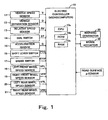
- FIG. 1 schematically shows the structure of a collision preventing apparatus according to this embodiment.
- This collision preventing apparatus has an electric controller 10 mounted on a vehicle.
- the electric controller 10 comprises a microcomputer which includes a CPU 10a, a ROM 10b, a RAM 10c, and the like that are connected with each other by an unillustrated bus.
- the CPU 10a executes a program described below and stored in the ROM 10b while utilizing a temporary storage function of the RAM 10c.
- the electric controller 10 is connected to a vehicle speed sensor 11, an obstacle sensor serving as a vehicle separation sensor 12, a relative speed sensor 13, a dial switch 14, an acceleration sensor 15, a shift lever switch 16, a brake switch 17, a left front wheel speed sensor 18, a right front wheel speed sensor 19, a left rear wheel speed sensor 20, and a right rear wheel speed sensor 21.
- the CPU 10a receives the signals from these sensors and switches.
- the electric controller 10 is connected to a warning apparatus 30 and a brake actuator 40, and the CPU 10a supplies prescribed signals thereto.
- the vehicle speed sensor 11 senses the speed of the driven vehicle (the vehicle being driven) and outputs the speed V of the driven vehicle (the driven vehicle speed).
- the vehicle separation sensor 12 includes laser radar, and it measures the distance (vehicle separation) between the driven vehicle and the preceding vehicle (the vehicle positioned in front of the driven vehicle, also referred to the vehicle in front), and it outputs the vehicle separation D.
- the vehicle separation sensor may be a sensor which measures the vehicle separation D using milliwave radar, or it may be a sensor which measures the vehicle separation D using a stereo image recognition method.
- the relative speed sensor 13 constitutes a portion of a preceding vehicle running condition detecting means which detects the running condition of the preceding vehicle. It is a Doppler sensor using milliwaves, and it measures and outputs the relative speed RV between the driven vehicle and the preceding vehicle.
- the dial switch 14 can be switched by the driver to selectively take one of seven positions. It outputs a selected position signal ST corresponding to each position to which it is operated.
- the dial switch 14 forms a portion of a parameter storing means which stores a plurality of sets of parameters, which are the idle running time ⁇ which is a parameter (referred to below as a parameter) which determines the idle running time ⁇ , ⁇ which is a parameter which determines the assumed deceleration ⁇ g of the driven vehicle, and the headway time Td which is a parameter which determines the suitable vehicle separation Dt.
- a parameter a parameter which determines the idle running time ⁇
- ⁇ which is a parameter which determines the assumed deceleration ⁇ g of the driven vehicle
- Td which is a parameter which determines the suitable vehicle separation Dt.
- the acceleration sensor 15 is of the semiconductor type. It senses the acceleration acting on the driven vehicle in the fore and aft direction and outputs an acceleration signal G.
- the shift lever switch 16 detects the shift lever position (parking position P, reverse position R, drive position D, etc.) of an unillustrated automatic transmission of the driven vehicle and outputs a signal POS corresponding to the detected shift lever position.
- the brake switch 17 determines (detects) whether the brake pedal of the driven vehicle, which is omitted from the drawings, is in an operating or nonoperating state, and it outputs a signal STOP which has a value of 1 when the pedal is being operated and a value of 0 when it is not being operated. It forms a portion of a brake operation determining means which determines whether the brake apparatus is being operated by the driver.
- the left front wheel speed sensor 18 and the right front wheel speed sensor 19 detect and output the wheel speed VFL of the left front wheel (a non-driven wheel) and the wheel speed VFR of the right front wheel (a non-driven wheel), respectively.
- the left rear wheel speed sensor 20 and the right rear wheel speed sensor 21 detect and output the wheel speed VRL of the left rear wheel (a driven wheel) and the wheel speed VRR of the right rear wheel (a driven wheel), respectively.
- the warning apparatus 30 includes an unillustrated display and a warning sound generating apparatus. In response to instructions from the CPU 10a of the electric controller 10, the apparatus 30 displays necessary information and generates necessary warning sound.
- the brake actuator 40 controls the braking hydraulic pressure (brake hydraulic pressure) of an unillustrated brake apparatus independently of the braking hydraulic pressure of the brake master cylinder which is increased and decreased by the operation of the brake pedal, to vary the braking force generated by the hydraulic brakes of the left and right front wheels and of left and right rear wheels.
- the brake actuator 40 may correspond to the electric motor.
- the object of this collision preventing apparatus is to guarantee a safe distance between the driven vehicle and the preceding vehicle. Based on the conditions and the like of the preceding vehicle and the driven vehicle, it carries out (generates) a first warning, then it urges braking operation by the driver by carrying out (generating) a second warning, and it carries out intervention braking in which it automatically operates the braking apparatus if braking operation is not carried out even after the second warning is generated.
- this collision preventing apparatus As the first warning, this collision preventing apparatus generates a relatively gentle warning sound (for example, a warning sound with a normal volume which is intermittently generated) from the warning sound generating apparatus of the warning apparatus 30.
- a warning sound is generated from the warning sound generator of the warning apparatus 30 which draws the attention of the driver even more than the first warning (such as a warning sound with a normal volume which is continuously generated), and a mark which draws the driver's attention is displayed on the display of the warning apparatus.
- a warning similar to the second warning is carried out, but the volume of the warning sound is increased.
- the closest approach distance dmin (the distance when the driven vehicle most closely approaches the preceding vehicle) shown in FIG. 2 is predicted by calculations based on the condition of the preceding vehicle, the condition of the driven vehicle, and the like, and the first warning, the second warning, and intervention braking are performed when it is determined that the closest vehicle separation dmin cannot guarantee a prescribed suitable vehicle separation Dt (i.e., dmin ⁇ Dt).
- the first warning, the second warning, or intervention braking it is determined whether to perform any of the first warning, the second warning, or intervention braking by varying the parameters used to obtain the closest approach distance dmin (the parameters being the idle running time ⁇ and the driven vehicle assumed deceleration ⁇ g (g is the acceleration due to gravity), as described below), and by varying the parameter for determining the suitable vehicle separation Dt (the parameter being the headway time Td described below).
- the method of determining the closest approach distance dmin will be described, firstly.
- the closest approach distance dmin is determined using these assumptions above and the actual vehicle separation D (the distance between the preceding vehicle and the driven vehicle) at the present time.
- the closest approach distance dmin In order to predict (determine) the closest approach distance dmin, it is necessary to consider the four cases of (1) the case in which the preceding vehicle first stops and then the driven vehicle stops, (2) the case in which the preceding vehicle is stopped from the beginning, (3) the case in which the driven vehicle most closely approaches the preceding vehicle which is moving after the elapse of the idle running time ⁇ , and (4) the case in which the driven vehicle most closely approaches the preceding vehicle before the elapse of the idle running time ⁇ . More concretely, the closest approach distance dmin is determined as described below.
- FIG. 3 shows the changes in speed with respect to time of the preceding vehicle and the driven vehicle for the case in which the preceding vehicle first stops and then the driven vehicle stops.
- FIG. 4 shows the changes in position with respect to time of the preceding vehicle and the driven vehicle for the same case.
- tf Vf / ( ⁇ f ⁇ g )
- Equation 7 V ⁇ ⁇ + V 2 / ( 2 ⁇ ⁇ ⁇ g )
- dmin ⁇ D + Vf 2 / ( 2 ⁇ ⁇ f ⁇ g ) ⁇ - ⁇ V ⁇ ⁇ + V 2 / ( 2 ⁇ ⁇ ⁇ g ) ⁇
- Equation 8 The condition in which Equation 8 is applicable (the condition in which the closest approach distance dmin should be calculated with using Equation 8, referred to below simply as "condition of applicability") is that the time tf until the preceding vehicle stops is less than or equal to the time tj until the driven vehicle stops. Therefore, based on the above Equation 4 and the above Equation 6, the condition in which Equation 8 is applicable is expressed by the following Equation 9. Vf ⁇ ⁇ f ⁇ g ⁇ + V / ( ⁇ ⁇ g ) ⁇
- Equation 12 The condition of applicability in this case is expressed by the following Equation 13 for the similar reason why the above-described Equation 11 is obtained.
- FIG. 5 shows the changes in speed with respect to time of the driven vehicle and the preceding vehicle for the case in which the driven vehicle most closely approaches the preceding vehicle which is decelerating at a deceleration ⁇ f ⁇ g ( ⁇ f ⁇ g > 0) after an idle running time of the driven vehicle has elapsed.
- FIG. 6 shows the changes in position with respect to time of the driven vehicle and the preceding vehicle for this case.
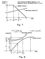
- FIG. 7 shows the changes in speed with respect to time of the driven vehicle and the preceding vehicle for this case in which the driven vehicle most closely approaches the preceding vehicle while the preceding vehicle is decelerating at a deceleration ⁇ f ⁇ g ( ⁇ f ⁇ g ⁇ 0), i.e., when it is accelerating
- FIG. 8 shows the changes in position with respect to time of the driven vehicle and the preceding vehicle for the same case in Fig. 7.
- Equation 16 ( V - Vf + ⁇ ⁇ g ⁇ ⁇ ) / ( ⁇ ⁇ g - ⁇ f ⁇ g )
- Equation 18 the position Dj of the driven vehicle after time tc (i.e., when the time tc has elapsed) is expressed by the following Equation 18.
- Dj V ⁇ ⁇ + V ( tc - ⁇ ) - ⁇ ⁇ g ⁇ ( tc - ⁇ ) 2 / 2
- Equation 19 D - [ ( V + ⁇ ⁇ g ⁇ ⁇ - Vf ) 2 / ⁇ 2 ( ⁇ ⁇ ⁇ f ) ⁇ g ⁇ - ⁇ ⁇ g ⁇ ⁇ 2 / 2 ]
- Vs ( ⁇ f ⁇ V - ⁇ ⁇ Vf + ⁇ ⁇ ⁇ f ⁇ g ⁇ ⁇ ) / ( ⁇ f - ⁇ )
- Equation 21 the conditions expressed by the following Equation 21 are added to the conditions of applicability of the above Equation 19 and the above Equation 20.
- Equation 23 is satisfied in the case in which the preceding vehicle is accelerating ( ⁇ f ⁇ g ⁇ 0). Further, the conditions of the above Equation 11 (Vf ⁇ Vf0) are added to the conditions of applicability of the above Equation 19 and the above Equation 20.
- FIG. 9 shows the changes in speed with respect to time of the driven vehicle and the preceding vehicle for the case in which the driven vehicle most closely approaches the preceding vehicle before the elapse of idle running time ⁇
- FIG. 10 shows the changes in position with respect to time of the driven vehicle and the preceding vehicle for the same case.
- the driven vehicle most closely approaches the preceding vehicle when the speed V' of the driven vehicle and the speed Vf' of the preceding vehicle become the same speed Vs.
- the time at which the speeds of both vehicles become the equal speed Vs is tc
- Equation 24 is established since the speed V' of the driven vehicle is a fixed speed V, with taking the speed of the preceding vehicle into consideration.
- V Vf - ⁇ f ⁇ g ⁇ tc
- Equation 27 D - ( V - Vf ) 2 / ⁇ - 2 ⁇ ( ⁇ f ⁇ g ) ⁇
- Equation 27 and Equation 28 The conditions of applicability of the above Equation 27 and Equation 28 are that time tc has elapsed before the elapse of the idle running time ⁇ (tc ⁇ ⁇ ), and therefore, the following Equation 29 is the conditions of applicability of the above Equation 27 and Equation 28. Further, since it is necessary that the speed Vf of the preceding vehicle at the present time has exceeded the sensing resolution Vf0 of the relative speed sensor, the speed Vf of the preceding vehicle at the present time is smaller than the speed V of the driven vehicle, and the preceding vehicle is accelerating, the following Equations 30 - 32 are obtained as the conditions of applicability of the above Equation 27 and Equation 28. Vf ⁇ ⁇ f ⁇ g ⁇ ⁇ + V Vf ⁇ Vf 0 Vf ⁇ V ⁇ f ⁇ 0
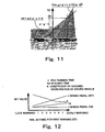
- FIG. 11 shows the regions for each of the above-described cases (1) - (4), in which the horizontal axis is the deceleration ⁇ f ⁇ g of the preceding vehicle and the vertical axis is the speed Vf of the preceding vehicle.
- the first warning is carried out to encourage braking operation by the driver
- the second warning is carried out to further encourage braking operation by the driver
- intervention braking is carried out in which the braking apparatus is automatically operated.
- the idle running time ⁇ for the first warning (the first idle running time) is set based on the case in which braking operation is carried out with the most tense timing during the normal driving operation by the driver.
- the idle running time ⁇ for the second warning (the second idle running time) is set based on the case in which braking operation is carried out with the most tense timing during emergency driving operation by the driver.
- the idle running time ⁇ for intervention braking (the second or third idle running time) is set based on the premise that an automatic braking operation which is not depending upon braking operation by the driver is carried out.
- the idle running time ⁇ includes at least the sum ( ⁇ 1) of the time for the sensors 11 - 21 and the electric controller 10 shown in FIG. 1 to recognize the conditions and the like of the preceding vehicle and the driven vehicle (particularly the deceleration ⁇ f ⁇ g of the preceding vehicle), and the calculation processing time necessary to determine the need for the first or second warning or intervention braking, and the time ( ⁇ 2) from when the electric controller 10 generates an instruction signal to the brake actuator 40 to generate braking force until the brake hydraulic pressure actually rises and braking force is generated.
- the idle running time ⁇ for the first warning and the second warning is the sum of the above-described ⁇ 1 and ⁇ 2 in the case in which the brake pedal is being operated (when the value of the brake switch signal STOP is 1).
- ⁇ 1 is a time which is always necessary even when the brake pedal is being operated.
- this time period is set as ⁇ 1.
- the idle running time ⁇ for the first warning when the brake pedal is not being operated can be selected by the dial switch 14 to be a value larger than the sum of the above-described ⁇ 1 and ⁇ 2 by the length of time until the driver begins operation of the brake pedal (see FIG. 12).
- the idle running time ⁇ for the second warning when the brake pedal is not being operated is made a prescribed fixed value (a constant) equal to the length of time until the start of brake pedal operation by the driver added to the sum of the above ⁇ 1 and ⁇ 2.
- the idle running time ⁇ for intervention braking is the sum of the above ⁇ 1 and ⁇ 2.
- the first warning is a warning which initially urges the driver to perform braking operation, so it is necessary for it to be generated with a timing such that as a result of the warning, safe deceleration can be performed if the driver carries out normal braking operation. Therefore, the assumed deceleration ⁇ g of the driven vehicle for the first warning can be selected by the dial switch 14 to be a relatively large value among decelerations which are performed by the driver during normal driving operation. A relatively large value is used because if the assumed deceleration ⁇ g of the driven vehicle is too small, the warning is generated early, and the driver may find the warning to be annoying. Note that, as shown in FIG.
- a coefficient K is actually selected by the dial switch 14, and the assumed deceleration ⁇ g of the driven vehicle is determined by multiplying it (K) by the actual road surface coefficient of friction ⁇ max which is found by a method to be described below.
- the second warning is a warning which strongly urges the driver to perform braking operation, and it is generated with a timing such that if braking operation is not carried out as a result of the second warning, intervention braking must be,immediately performed.
- the assumed deceleration ⁇ g of the driven vehicle for the second warning is a value equal to the assumed deceleration ⁇ g of the driven vehicle for intervention braking, and it is made a larger deceleration than the assumed deceleration ⁇ ⁇ g of the driven vehicle for the first warning (namely, it is a larger deceleration than that for normal braking operation by the driver).
- the coefficients K for the second warning and for intervention braking are a value equal to each other of less than 1 (such as 0.6), and they are set to a value larger than the coefficient K for the first warning.
- the coefficient K for the second warning and intervention braking is made a value smaller than 1. This is so that when the deceleration of the preceding vehicle increases, some margin is left to further increase the deceleration of the driven vehicle by braking operation and the like by the driver.
- the value of the above-described coefficient K may be such as to vary with the road surface coefficient of friction ⁇ max so as, for example, to increase as the road surface coefficient of friction ⁇ max decreases.
- a slippery road surface a road surface having a small road surface coefficient of friction ⁇ max
- the driver normally performs braking operation with the same feeling as when driving on a normal road surface, so that deceleration on a slippery road surface is close to the deceleration at the time of braking on a normal road surface. Therefore, the coefficient K for a slippery road surface should be larger than the coefficient K for a normal road surface. Accordingly, as described above, by making the coefficient K for the first and second warning and intervention braking larger as the road surface coefficient of friction ⁇ max becomes smaller, the first warning, the second warning, and intervention braking can be carried out so as to agree with actual driving.
- the first warning is preferably not generated insofar as the driver is performing normal driving operation. On the other hand, it is preferred that the first warning be generated as early as possible.
- the length of time for a driver to change a position of his foot from on the accelerator pedal to on the brake pedal which is part of the idle running time ⁇ , differs depending upon the driver.
- a driver who takes a long time to switch his foot (position of his foot) generally carries out braking with a small deceleration, and maintains a relatively large headway (headway time Td).
- the headway time Td, the idle running time ⁇ , and the coefficient K (and accordingly the assumed deceleration ⁇ g) for the first warning can be varied by the dial switch 14, and the timing of the first warning can be made to match the characteristic of each driver (see FIG. 12).
- the structure may be such as to detect the length of time for the driver to change his foot position from on the accelerator pedal to on the brake pedal during normal driving and to automatically vary the idle running time ⁇ , the headway time Td, and the coefficient K based on the detected time to change his foot position.
- the structure may also be such that the minimum value of the detected time to change the foot position and the maximum value of the detected deceleration are learned, the headway time Td, the idle running time ⁇ , and the coefficient K are automatically varied based on this learned result.
- the structure may be such that the idle running time ⁇ is learned as being longer when a cruise control apparatus is operating than when it is not operating, or such that the coefficient K is increased as the road surface coefficient of friction ⁇ max decreases.
- the suitable vehicle separation Dt will be described.
- the first warning, the second warning, and intervention braking are performed when the closest approach distance dmin which is determined from the above Equation 8, Equation 12, Equation 19, and Equation 27 is smaller than the suitable vehicle separation Dt (dmin ⁇ Dt). Therefore, in a state in which the preceding vehicle is being followed, the suitable vehicle separation Dt is selected based on the concept that even in the case in which the preceding vehicle decelerates by braking, safety can be guaranteed (stopping can be safely performed) by the equivalent (similar) braking after a prescribed reaction time.
- the suitable vehicle separation is selected to be a distance necessary for the driven vehicle to stop while leaving a prescribed distance from the preceding vehicle, in the case in which the driven vehicle is following the preceding vehicle at approximately the same speed, if the driven vehicle begins decelerating at a deceleration which is equal to the deceleration of the preceding vehicle after the elapse of a prescribed length of time from the point at which the preceding vehicle starts to decelerate at a prescribed deceleration.
- Equation 34 it is given by Equation 34 shown below.
- Dt Td ⁇ Vs + d 0
- Td is the headway time, and when the driven vehicle follows the preceding vehicle at (approximately) the same speed as the preceding vehicle, it is a value obtained by dividing the vehicle separation between the driven vehicle and the preceding vehicle which the driver normally maintains by the speed V of the driven vehicle at that time.
- the vehicle separation which the driver maintains when following varies in accordance with the vehicle speed at that time, but the headway time Td obtained by dividing the vehicle separation by the vehicle speed does not vary much as long as the same driver is concerned (it is approximately constant).
- the concept of headway time Td was introduced.
- the value Td-Vs in Equation 34 is sometimes called the headway (headway distance).
- the first warning, then the second warning, and finally intervention braking are carried out. Accordingly, the headway time Td for the first warning (the first time Td) is set to be largest, the headway time Td for the second warning (the second time Td) is set to be next largest, and the headway time Td for intervention braking (the third time Td) is set to be the smallest. As shown in FIG. 12, the headway time Td for the first warning can be varied by operation of the dial switch 14 to agree with differences among drivers.
- the headway time Td for the second warning is set to be a fixed value less than or equal to the minimum value of the headway time Td for the first warning
- the headway time Td for intervention braking is set to be a fixed value less than or equal to the headway time Td for the second warning.
- the suitable vehicle separation which is determined by the headway time Td for the first warning may also be referred to as the first suitable vehicle separation
- the suitable vehicle separation which is determined by the headway time Td for the second warning may also be referred to as the second suitable vehicle separation
- the suitable vehicle separation which is determined by the headway time Td for intervention braking may also be referred to as the second suitable vehicle separation or the third suitable vehicle separation.
- the value d0 in Equation 34 is the distance for guaranteeing a fixed stopping distance, which is called the margin vehicle separation (for example, the distance which should exist between the preceding vehicle and the driven vehicle when the driven vehicle is stopped with respect to a preceding vehicle which has stopped).
- the value d0 is set to a prescribed fixed value (such as 1.5 meters).
- the margin vehicle separation d0 is determined taking into consideration the detecting error of the plurality of sensors.
- a first warning is carried out with respect to a front end collision
- a first warning, a second warning, and intervention braking are carried out to maintain a vehicle separation with respect to a vehicle which cuts in front during movement.
- the closest approach distance dmin and the speed at the time of closest approach Vs are set by the below-described Equation 35 and Equation 36, and the above-described first warning, second warning, and intervention braking are carried out.
- the conditions of applicability are as set forth in Equation 37.
- the headway time Td is made either a constant or a variable based on the time for lane changing by steering operation of the driven vehicle.
- the idle running timer ⁇ and the coefficient K can be same values as for the above-described first warning.
- the closest approach distance dmin and the speed at the time of closest approach Vs are set as shown by the following Equation 38 and Equation 39, and the first warning, the second warning, and intervention braking are carried out when the closest approach distance dmin becomes smaller than the suitable vehicle separation Dt.
- the headway time Td, the idle running time ⁇ , and the coefficient K can have the same values as for the above-described first warning, second warning, and intervention braking.
- the target deceleration must also be determined for the above-described cases (1) - (4).
- the idle running time ⁇ on the right side of Equation 42 is made to be equal to the above-described ⁇ 1 taking into considering only the time lag for recognition and processing.
- the idle running time ⁇ on the right side of Equation 44 is made equal to the above-described ⁇ 1 taking into consideration only the lag time for recognition and processing.
- the speed Vs at the time of closest approach is given by the above Equation 20.
- Equation 46 is obtained.
- the idle running time ⁇ is made equal to just the lag time ⁇ 1 for processing and recognition by the sensors and the electric controller, and the headway time Td is made equal to a value (set by the dial switch 14) that is used to determine whether to perform the first warning.
- ⁇ r ⁇ g ( ⁇ f ⁇ g ⁇ ( D - V ⁇ Td - d 0 ) + ( Vf - V ) 2 / 2 ) / B
- Equation 46 the value B is given by the following Equation 47.
- B D - ( Vf - ⁇ f ⁇ g ⁇ ⁇ ) ⁇ Td + ( Vf - V ) ⁇ ⁇ - ( ⁇ f ⁇ g ⁇ ⁇ 2 ) / 2 - d 0
- the value B in the above Equation 46 is a value which decreases as the driven vehicle approaches the preceding vehicle.
- measurement errors in the speed Vf of and the deceleration ⁇ f of the preceding vehicle due to noise and the like greatly influence the value ⁇ r ⁇ g of the target deceleration GT, and there are cases in which this value ⁇ r ⁇ g becomes inaccurate (unstable).
- Equation 48 Coefficient K is a value which is used when determining whether to carry out the first warning, the second warning, and intervention braking, respectively.
- ⁇ r ⁇ g K ⁇ ⁇ max ⁇ g
- the target deceleration GT is determined by the above Equation 48.
- the coefficient K is the value which is used when determining whether to carry out the first warning, the second warning, and intervention braking, respectively.
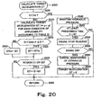
- the CPU 10a of the electric controller 10 executes a program shown by the flow charts in FIGS. 14 - 23.
- Step 1405 it carries out initializing processing of various flags and the like, and it proceeds to Step 1410 and sets the value of the state variable MODE to 0.
- Step 1415 the CPU 10a proceeds to Step 1415 in which it obtains signals from various sensors and switches 11 - 21 and performs prescribed calculations to obtain the vehicle separation D, the speed Vf of the preceding vehicle, the deceleration ⁇ f ⁇ g of the preceding vehicle, the speed V of the driven vehicle, the deceleration ⁇ g of the driven vehicle, the brake switch signal STOP, the shift lever position signal POS, the dial switch selected position signal ST, the road surface coefficient of friction ⁇ max, the actual deceleration GD, the road surface slope ⁇ , and the like.
- the speed Vf of the preceding vehicle and the deceleration ⁇ f ⁇ g of the preceding vehicle and the like indicate the running condition of the preceding vehicle.
- the speed V of the driven vehicle, the deceleration ⁇ g of the driven vehicle, the brake switch signal STOP, the shift lever position signal POS, and the like indicate the running condition of the driven vehicle.
- the speed Vf of the preceding vehicle is found by adding the speed V of the driven vehicle to the output signal RV of the relative speed sensor 13.
- the deceleration ⁇ f ⁇ g of the preceding vehicle is the value found by subtracting from the speed Vf of the preceding vehicle the speed Vfold of the preceding vehicle a prescribed length of time earlier and dividing this by the prescribed length of time.
- the deceleration ⁇ g of the driven vehicle is found based on a value obtained by subtracting from the speed V of the driven vehicle the speed Vold of the driven vehicle a prescribed length of time earlier and dividing this by the prescribed length of time.
- Step 1420 it investigates the value of the state variable MODE, and it proceeds to a mode (a subroutine) corresponding to the value of the state variable MODE.
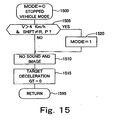
- the value of the state variable MODE is set to 0, so the CPU 10a proceeds to Step 1425 and it begins the execution of the subroutine for MODE-0 (vehicle stopping mode) shown in FIG. 15 from Step 1500. (MODE-0 ... Vehicle stopping mode)
- Step 1505 the CPU 10a determines whether the speed V of the driven vehicle is larger than a prescribed speed (here, 4 kilometers per hour) and if the signal POS of the shift lever switch 16 is neither the park position P nor the reverse position R to thereby determine whether the driven vehicle is moving.
- the vehicle is stopped, so the speed V of the driven vehicle is less than or equal to the prescribed speed, or the shift position is the park position P or the reverse position R.
- Step 1505 the CPU 10a makes a determination of "No" and proceeds to Step 1510, and in Step 1510 it makes a sound and an image "None".
- Step 1515 the CPU 10a sets the target deceleration GT to 0 and proceeds to Step 1595, and it returns to Step 1430 of the flow chart in FIG. 14 by way of Step 1595.
- Step 1430 the CPU 10a performs processing for outputting a warning sound and a warning image by use of the warning apparatus 30.
- the warning sound and the warning image were set to "None" in Step 1510 of FIG. 15, so the warning apparatus 30 does not generate a warning sound or display a warning image by the execution of Step 1430.
- Step 1515 of above-described FIG. 15 the target deceleration GT was set to 0 in Step 1515 of above-described FIG. 15, so the output of an instruction signal to the brake actuator 40 is not carried out by the execution of Step 1435. Then, the CPU 10a returns to Step 1415. Subsequently, as long as the vehicle is stopped (as long as the condition continues that a determination of "No" is made in Step 1505 of FIG. 15) , the CPU 10a repeatedly executes the above-described processing.
- Step 1505 of FIG. 15 by way of Step 1425 of FIG. 14, it makes a determination of "Yes" in Step 1505 to proceed to Step 1520, and it sets the value of the state variable MODE to 1.
- Steps 1510, 1515, and 1595 the CPU 10a returns to Step 1430 of FIG. 14 by way of Steps 1510, 1515, and 1595, and it performs the processing of Step 1430 and Step 1435.
- Steps 1510 and 1515 the sound and the image were set to "None" and the target deceleration GT were set to 0. Therefore, even if the processing of Steps 1430 and 1435 is carried out, a warning sound and image are not generated, and an instruction signal is not sent to the brake actuator 40.
- the CPU 10a performs the processing of Step 1415 of FIG. 14, and it investigates the value of the state variable MODE in Step 1420 .
- the value of the state variable MODE is set to 1, so the CPU 10a proceeds to Step 1440, and it begins the processing of the subroutine for MODE-1 (non-warning mode) shown in FIG. 16 from Step 1600.
- Step 1605 the CPU 10a proceeds to Step 1605, and it determines whether the speed V of the driven vehicle is larger than a prescribed speed (here 4 kilometers per hour) and if the signal POS from the shift lever switch 16 is neither the park position P nor the reverse position R, whereby it is determined whether the driven vehicle is moving.
- the CPU 10a makes a determination of "Yes" in Step 1605 and proceeds to Step 1610.
- Step 1610 it begins the processing of warning-intervention instruction issuance subroutine shown in FIG. 17 from Step 1700.
- Step 1705 the CPU 10a proceeds to Step 1705, and in Step 1705 it sets the parameters for intervention braking.
- the idle running time ⁇ is set to the above-described idle running time ⁇ for intervention braking
- the headway time Td is set to the above-described headway time for intervention braking Td.
- Step 1710 it commences processing of the warning determining subroutine shown in FIG. 18 from Step 1800, it proceeds to Step 1805 to determine whether the speed Vf of the preceding vehicle is smaller than the above-described prescribed speed Vf0 with its sign reversed (such as -6 kilometers per hour).
- Step 1805 the CPU 10a makes a determination of "Yes" in the above Step 1805, it proceeds to Step 1810 to set the closest approach distance dmin and the speed at the time of closest approach Vs according to the above Equation 35 and the above Equation 36, and it proceeds to Step 1815.
- the preparation is carried out for warning determination for a front end collision described above in (5).
- Step 1805 when the speed Vf of the preceding vehicle is greater than or equal to a speed equal to the prescribed speed Vf0 with its sign reversed, the CPU 10a makes a determination of "No" in Step 1805, it proceeds to Step 1820 to determine whether the speed Vf of the preceding vehicle is smaller than the above-described prescribed speed Vf0 (such as +6 kilometers per hour).
- Step 1805 if the speed Vf of the preceding vehicle is smaller than the prescribed speed Vf0, the above Equation 13 is established (see Step 1805).
- the CPU 10 proceeds to Step 1825, it sets the value of the closest approach distance dmin according to the above Equation 12, it makes the speed at the time of closest approach Vs equal to 0, and it proceeds to Step 1815.
- the preparation for warning determination for the case in which the preceding vehicle is initially stopped as described above in (2) is carried out.
- Step 1820 if the speed Vf of the preceding vehicle is greater than or equal to the prescribed speed Vf0, the CPU 10a makes a determination of "No" in Step 1820, it proceeds to Step 1830, and it determines whether the condition at the present time satisfies the above Equation 9 and Equation 10.
- Step 1820 the CPU 10a makes a determination of "Yes” in Step 1830 and proceeds to Step 1835 to set the value of the closest approach distance dmin according to the above Equation 8 and to make the speed at the time of closest approach Vs equal to 0, and it proceeds to Step 1815.
- Step 1835 the preparation for warning determination for the case described above in (1) in which the preceding vehicle first stops and then the driven vehicle stops is carried out.
- the CPU 10a makes a determination of "No" in Step 1830, it proceeds to Step 1840, and it determines whether the condition at the present time satisfies the above Equation 22.
- Step 1830 it is determined in Step 1830 that the above Equation 23 is satisfied, and it is determined in Step 1820 that the conditions of the above Equation 11 are satisfied (Vf ⁇ Vf0). Therefore, all of the conditions of applicability of the above Equation 19 and the above Equation 20 (the above Equation 22, Equation 23, and Equation 11) are satisfied (in the case in which ⁇ f ⁇ 0, the above Equation 23 is established). Accordingly, the CPU 10a proceeds from Step 1840 to Step 1845, it sets the value of the closest approach distance dmin according to the above Equation 19, it sets the speed at the time of closest approach Vs according to the above Equation 20, and it proceeds to Step 1815. As a result, the preparation for warning determination is carried out for the case described above in (3) in which the driven vehicle most closely approaches the preceding vehicle which is moving after elapse of the idle running time ⁇ .
- Step 1840 the CPU 10a makes a determination of "No" in Step 1840 and proceeds to Step 1850.
- Step 1850 it determines whether the conditions at the present time satisfy the above Equation 31 and the above Equation 32.
- Step 1850 the CPU 10a makes a determination of "Yes" in Step 1850 and proceeds to Step 1855.
- the CPU 10a sets the value of the closest approach distance dmin according to Equation 27, it sets the speed Vs at the time of closest approach according to Equation 28, and it proceeds to Step 1815.
- the preparation for warning determination is carried out for the case described above in (4) in which the driven vehicle most closely approaches the preceding vehicle before the elapse of the idle running time ⁇ .
- Step 1850 the CPU 10a proceeds to Step 1860, it sets the value of the closest approach distance dmin to the vehicle separation D at the present time, it sets the value of the speed at the time of closest approach Vs (the vehicle speed at the time of closest approach) to the speed V of the driven vehicle, and it proceeds to Step 1815.
- the preparation for warning determination is carried out for the case described above in (6) for countermeasures against a vehicle cutting in front.
- Step 1815 the CPU 10a determines whether the closest approach distance dmin has become smaller than the suitable vehicle separation Dt (dmin ⁇ Dt).
- each parameter was set to the parameter for intervention braking, so the determination in Step 1815 becomes a determination of whether to carry out intervention braking.
- the CPU 10a makes a determination of "Yes" in Step 1815, it proceeds to Step 1870 and sets the value of a instruction issuance permission flag F to 1, and it returns to Step 1710 of FIG. 17 by way of Step 1895.
- Step 1815 the CPU 10a makes a determination of "No" in Step 1815 and proceeds to Step 1875. After it sets the value of the instruction issuance permission flag F to 0 in Step 1875, it returns to Step 1710 by way of Step 1895.
- Step 1710 When the CPU 10a returns to Step 1710, it checks the value of the instruction issuance permission flag F. If the value of this flag F is 1, it proceeds to Step 1715, it establishes a condition in which intervention braking is permitted, and it proceeds to Step 1795. On the other hand, if the value of the instruction issuance permission flag F is 0, it proceeds from Step 1710 to Step 1720, and in Step 1720 it sets parameters for the second warning. Namely, the idle running time ⁇ is set to the idle running time ⁇ for the second warning, the assumed deceleration of the driven vehicle ⁇ g is set to the assumed deceleration of the driven vehicle for the second warning ⁇ g, and the headway time Td is set to the above headway time for the second warning Td.
- Step 1725 the CPU 10a proceeds to Step 1725, and in the same manner as in the above Step 1710, it performs processing of the warning determining subroutine shown in FIG. 18.
- the CPU 10a since each parameter has been set to the value for the second warning in Step 1720 at the present time, it is determined whether to carry out the second warning.
- the value of the instruction issuance permission flag F is set to 1 in Step 1870, and when it should not be carried out, the value of the instruction issuance permission flag F is set to 0 in Step 1875.
- Step 1895 when the CPU 10a has returned to Step 1725 of FIG. 17 by way of Step 1895, if the value of the instruction issuance permission flag F is 1, the CPU 10a proceeds to Step 1730 where a condition in which the second warning is permitted is established, and it proceeds to Step 1795. On the other hand, if the value of the instruction issuance permission flag F is 0, the CPU 10a proceeds to Step 1735, and in Step 1735 the parameters for the first warning are set. Namely, based on the selected position signal ST from the dial switch 14 and parameters selected from the table shown in FIG.
- the CPU 10a sets the idle running time ⁇ to an idle running time for the first warning (first idle running time) ⁇ for an off state of the brake (when the signal STOP from the brake switch 17 is 0 and the brake apparatus is in a non-operating state), it sets the assumed deceleration of the driven vehicle ⁇ g to the above-described assumed deceleration of the driven vehicle for the first warning (the first assumed deceleration for the driven vehicle) ⁇ g, and it sets the headway time Td to the headway time for the first warning (the first headway time) Td.
- Step 1740 the CPU 10a proceeds to Step 1740, and in the same manner as in the above Step 1710, it performs processing of the warning determining subroutine shown in FIG. 18.
- the CPU 10a since each parameter has been set in Step 1735 to the value for the first warning at the present time, it is determined whether to perform the first warning.
- the value of the instruction issuance permission flag F is set to 1 in Step 1870, and when it should not be performed, the value of the instruction issuance permission flag F is set to 0 in Step 1875.
- Step 1740 when the CPU 10a returns to Step 1740 of FIG. 17 by way of Step 1895, if the value of the instruction issuance permission flag F is 1, it proceeds to Step 1745 and a state is established in which the first warning is permitted. On the other hand, if the value of the instruction issuance permission flag F is 0, it proceeds to Step 1750. In Step 1750 a state is established in which the warning is "None", and the CPU 10a proceeds to Step 1795.
- Step 1610 it investigates the results of the execution of the warning-intervention instruction issuance determining subroutine.
- the result is a state which permits the first warning or the second warning
- it proceeds to Step 1615 and sets the value of the state variable MODE to 2
- it proceeds to Step 1620.
- the CPU 10a proceeds to Step 1625 to set the value of the state variable MODE to 3, and it proceeds to Step 1620.
- the CPU 10a proceeds to Step 1620.
- Step 1605 the CPU 10a makes a determination of "No" and proceeds to Step 1635, then it proceeds to Step 1620.
- the shift lever position is the park position P or the reverse position R, the first warning, the second warning, and intervention braking are not carried out.
- Step 1620 the CPU 10a makes the sound and the image "None" and it proceeds to Step 1630 and sets the target deceleration GT to 0, after which it returns to Step 1430 of the flow chart of FIG. 14 by way of Step 1695.
- Step 1430 the CPU 10a carries out processing for outputting the warning sound and the warning image by use of the warning apparatus 30.
- the warning sound and image have been set to "None" in Step 1620 of FIG. 16, so the generation of a warning sound and display of a warning image are not performed by the warning apparatus 30 by the execution of Step 1430.
- the CPU 10a proceeds to Step 1435 and carries out output processing based on the target deceleration GT. However, since the target deceleration GT was set to 0 in Step 1630 of FIG. 16, an instruction signal is not output to the brake actuator 40 by the execution of Step 1435.
- Step 1415 the CPU 10a returns to Step 1415 and obtains (updates) each of the above data, and in Step 1420 it investigates the value of the state variable MODE.
- the result of Step 1610 in FIG. 16 is a state in which there is no warning, the value of the state variable MODE is maintained at 1, so the CPU 10a proceeds to Step 1440 and executes the above-described MODE-1 subroutine.
- Step 1445 the CPU 10a proceeds to Step 1445 and begins the processing of MODE-2 (warning mode) subroutine shown in FIG. 19 from Step 1900.
- the CPU 10a proceeds to Step 1450 and begins the processing of the MODE-3 (intervention braking mode) subroutine shown in FIG. 21 from Step 2100.
- Step 1725 or Step 1740 of FIG. 17 the value of the state variable MODE is thereby set to 2 in Step 1615 of FIG. 16, and the CPU 10a proceeds from Step 1420 to Step 1445 of FIG. 14.
- Step 1905 the CPU 10a makes a determination of "Yes" in Step 1905 and proceeds to Step 1910.
- Step 1910 it makes the value of the state variable MODE equal to 0 and then proceeds to Step 1915.
- the processing by the CPU 10a moves to MODE-0 (vehicle stopping mode) at the time of executing the main routine shown in FIG. 14.
- Step 1920 it is determined whether an obstacle is still present based on whether there are reflected waves of milliwave radar generated by the vehicle separation sensor 12. Then, if there are no reflected waves from the milliwave radar at this stage, the CPU 10 a makes a determination of "No" in Step 1920 and proceeds to Step 1925, it sets the value of the state variable MODE equal to 1, and it proceeds to Step 1915.
- Step 1920 makes a determination of "Yes” in Step 1920 and proceeds to Step 1930, and it sets parameters for the first warning in the same manner as in the above Step 17 35 (FIG. 17). Then, the CPU 10a proceeds to Step 1935 and performs processing of a warning determining subroutine of FIG. 18. Namely, it is determined by Step 1930 and Step 1935 whether a state occurs for performing the first warning. In other words, in these steps, it is determined whether a sufficiently safe vehicle separation is maintained. In this case, the idle running time ⁇ uses the value for an off state of the brake (for when the brake apparatus is not operating).
- Step 1875 of FIG. 18 the CPU 10a proceeds from Step 1935 to Step 1940, and in Step 1940 it determines whether the speed V of the driven vehicle is smaller than a speed which is smaller than the speed Vf of the preceding vehicle by a value m (such as 5 kilometers per hour). This is in order to ascertain that the speed V of the driven vehicle is a sufficiently smaller value than the speed Vf of the preceding vehicle ,and therefore, the situation is safe even if MODE-2 (warning mode) is completed.
- m such as 5 kilometers per hour
- Step 1940 If the speed V of the driven vehicle is smaller than a speed equal to the speed Vf of the preceding vehicle minus the speed m, the CPU 10a makes a determination of "Yes" in Step 1940 and proceeds to Step 1945. In Step 1945, it sets the value of the state variable MODE to 1, and then it proceeds to Step 1915. Step 1940 is provided because of the following reason. If the speed V of the driven vehicle becomes smaller than a speed equal to the speed Vf of the preceding vehicle minus the speed m, it is possible to avoid with certainty the situation in which the CPU 10a proceeds to Step 1945 to thereby end the MODE-2 warning mode and enter the MODE-1 non-warning mode, and then carries out the first warning again immediately after the entry to the MODE-1 non-warning mode.
- the margin vehicle separation d0 is preferably increased by a prescribed value d0 ⁇ (>0) and the value d0 + d0 ⁇ is used as d0 in Step 1815 of FIG. 18. This also makes it possible to avoid with certainty the situation in which the CPU 10a proceeds to Step 1945 to thereby end the MODE-2 warning mode and enter the MODE-1 non-warning mode and then carries out the first warning immediately after the entry to the MODE-1 non-warning mode.
- Step 1950 in the same manner as in the above Step 1705, the parameters for intervention braking are set.
- the CPU 10a makes a determination of "No" in the above Step 1940 and proceeds to the above Step 1950 and sets the parameters for intervention braking.
- Step 1950 and Step 1955 it is determined whether a state occurs for performing intervention braking.
- the value of the instruction issuance permission flag F is set to 1 in Step 1870 of FIG. 18, so the CPU 10a proceeds from the above Step 1955 to Step 1960 and sets the value of the state variable MODE to 3, and then it proceeds to Step 1915.
- the value of the instruction issuance permission flag F is set to zero in Step 1875 of FIG. 18, so the CPU 10a proceeds from the above Step 1955 directly to Step 1915.
- Step 1915 when beginning the processing of the MODE-2 (warning mode) subroutine, depending on whether the first warning was authorized (Step 1745 of FIG. 17) or the second warning was authorized (Step 1730 of FIG. 17), the CPU 10a instructs an output of a warning sound and image for carrying out a corresponding warning. Then, the CPU 10a proceeds to Step 1965. In Step 1965, it is determined whether a state occurs in which the brake pedal is being operated and braking force is being generated based on whether the value of the brake signal STOP is 1.
- Step 1965 If the brake pedal is being operated, the CPU 10a makes a determination of "Yes” in Step 1965 and proceeds to Step 1970.
- the target deceleration GT calculating subroutine shown in FIG. 20 is executed to find the target deceleration GT, and then Step 1430 of FIG. 14 is returned to by way of Step 1995.
- Step 1430 the CPU 10a has the warning apparatus 30 generate a warning sound or an image corresponding to the first warning or the second warning instructed in Step 1915 of FIG. 19. Then, the CPU 10a proceeds to Step 1435 and carries out processing based on the target deceleration GT, and it outputs a control signal for controlling the braking hydraulic pressure to the brake actuator 40 so that the absolute value of the actual deceleration GD will be equal to the absolute value of the target deceleration GT.
- Step 1980 it sets the value of the target deceleration GT to 0, and then it returns to Step 1430 of FIG. 14 by way of Step 1995.
- Step 1430 the CPU 10a makes the warning apparatus 30 generate a warning sound or an image instructed in Step 1915 of FIG. 19, and the driver is urged to perform braking operation.
- the target deceleration GT was set to 0 in Step 1980 of FIG. 19, no command signal is output to the brake actuator 40.
- MODE-2 warning mode
- the CPU 10a proceeds to MODE-0 (vehicle stopping mode), MODE-1 (non-warning mode), or MODE-3 (intervention braking mode), and when a state is continuing in which the first warning or the second warning should be carried out, processing is carried out for achieving necessary warning and brake assist control by Steps 1915, 1970, 1980, and the like.
- the CPU 10a begins the subroutine from Step 2000, it proceeds to Step 2005, and it determines whether the speed V of the driven vehicle is smaller than a prescribed low speed Va (a speed indicating that the driven vehicle is about to stop).
- a prescribed low speed Va a speed indicating that the driven vehicle is about to stop.
- the target deceleration GT is calculated in a state in which the driven vehicle requires braking force, so the speed V of the driven vehicle is larger than the prescribed low speed Va. Accordingly, the CPU 10a makes a determination of "No" in Step 2005 and proceeds to Step 2010.
- Step 2015 determines whether the vehicle separation D found by the vehicle separation sensor 12 (the distance towards an obstacle in front) is smaller than the recognition limit Dmin in distance of the vehicle separation sensor 12 increased by a prescribed distance ⁇ D (Dmin + ⁇ D). Normally, since the vehicle separation D which is found by the vehicle separation sensor 12 is larger than the recognition limit Dmin of the vehicle separation sensor 12 plus the prescribed distance ⁇ D (Dmin + ⁇ D), the CPU 10a makes a determination of "No" in Step 2015 and proceeds to Step 2020. In Step 2020 it stores the target deceleration GT found in the above Step 2010 as the value GTm.
- the CPU 10a makes a determination of "Yes” in Step 2015 and proceeds to Step 2025, and the CPU 10a uses, as the target deceleration GT for this time, the target deceleration which was stored as the value GTm in Step 2020 the previous time the main routine was executed.
- the structure is preferably such as to maintain the first or the second warning which is generated at that time.
- the corrective increase by the coefficient ⁇ is performed with the object of changing the target deceleration GT from the state shown in FIG. 25 (A) to the state shown in FIG. 25 (8) and of lowering the speed V of the driven vehicle at an earlier time such as by making the actual deceleration of the driven vehicle a large value, such as immediately after the start of intervention braking and as a result to smoothly decrease the target deceleration GT which is subsequently determined, thereby improving the brake feeling during intervention braking for stopping.
- Step 2030 If the current operating region is not region (1) or (2), the CPU 10a makes a determination of "No" in Step 2030 and proceeds directly to Step 2095.
- Step 2005 If the speed V of the driven vehicle has sufficiently decreased due to braking and has become smaller than the prescribed speed Va, when the CPU 10a proceeds to Step 2005, it makes a determination of "Yes" in Step 2005 and proceeds to Step 2040, and in Step 2040 it generates an instruction for maintaining the braking hydraulic pressure at that time. As a result, when the processing of Step 1435 of FIG. 14 is carried out, the braking hydraulic pressure is maintained at a constant value.
- the maintaining of the braking hydraulic pressure is a function which is added in order to prevent the driven vehicle from moving due to the idling torque (the drive torque of a vehicle which is generated when the engine of the vehicle is idling and which is transmitted to the drive wheels through the torque converter of the vehicle) when, as in the intervention braking in region (1) or (2) shown in FIG. 11 (Table 1), intervention braking is performed in order to stop the driven vehicle, and then the braking force due to intervention braking is canceled when the driven vehicle has stopped (or just before it stops).
- the idling torque the drive torque of a vehicle which is generated when the engine of the vehicle is idling and which is transmitted to the drive wheels through the torque converter of the vehicle
- Step 2045 it determines whether a state in which the speed V of the driven vehicle is 0 has continued for at least a prescribed length of time. If the state in which the speed V of the driven vehicle is 0 has continued for at least the prescribed length of time, the CPU 10a makes a determination of "Yes" in Step 2045 and it outputs an engine stop request to an unillustrated engine control computer which is connected to the electric control apparatus 10. As a result, the engine is automatically stopped. It is noted that it is also possible for Step 2045 and Step 2050 to be omitted.
- Step 2055 determines whether a state occurs in which the brake pedal is being operated and braking force is being generated (a state in which the brake apparatus is being operated) based on whether the value of the brake switch signal STOP is 1.
- Step 2060 an instruction is made to cancel the hydraulic pressure maintenance in the above Step 2040. This is because when the driver is operating the brake pedal and braking force is already being generated, it is no longer necessary to generate braking force by the brake actuator 40.
- the determination in Step 2055 may be carried out based on whether the hydraulic pressure generated by the brake master cylinder connected to the brake actuator 40 is at least a prescribed pressure.
- Step 2065 it sets the value of the target deceleration GT to 0, and it proceeds to Step 2095.
- Step 2095 the CPU 10a proceeds to Step 2095 directly without canceling hydraulic pressure maintenance.
- Step 1420 of FIG. 14 proceeds from Step 1420 of FIG. 14 to Step 1450, and it begins the processing of the MODE-3 (intervention braking mode) subroutine shown in FIG. 21 from Step 2100.
- Step 2110 it sets the value of the state variable MODE to 0 and then proceeds to Step 2115.
- the CPU 10a will processes MODE-0 (vehicle stopping mode) when it executes the main routine next time.
- Step 2120 it determines whether an obstacle is still present based on whether there are reflected waves of the milliwave radar generated by the vehicle separation sensor 12. If there are not reflected waves of the milliwave radar at this stage, the CPU 10a makes a determination of "No" in Step 2120 and proceeds to Step 2125. In Step 2125, it sets the value of the state variable MODE to 4, and it proceeds to Step 2115.
- Step 2120 If an obstacle is still present, the CPU 10a makes a determination of "Yes" in Step 2120, it proceeds to Step 2130, and it sets the parameters for intervention braking in the same manner as in the above Step 1705 (FIG. 17). Then, the CPU 10a proceeds to Step 2135 and performs processing of the warning determining subroutine of FIG. 18. Namely, in Step 2130 and Step 2135, it determines whether a state for performing intervention braking continues.
- Step 2140 it determines whether an object present in front of the driven vehicle is a stationary object by determining whether the speed Vf of the preceding vehicle is larger than the above-described prescribed speed Vf0.
- the CPU 10a makes a determination of "Yes" in Step 2140 and proceeds to Step 2145.
- Step 2145 it sets the value of the state variable MODE to 5, and then it proceeds to Step 2115. Due to the determination of a nonstationary object in Step 2140, vehicle separation control (MODE-5) is carried out during intervention braking with respect to the preceding vehicle which is moving (running).
- Step 2135 the value of the instruction issuance permission flag F is set to 1 in Step 1870 of FIG. 18. Therefore, the CPU 10a proceeds from Step 2135 to Step 2115.
- the CPU 10a proceeds to Step 2115.
- Step 2115 the CPU 10a generates an instruction for outputting a warning sound and image for carrying out a warning corresponding to intervention braking. Then, the CPU 10a proceeds to Step 2150, it performs the subroutine for calculating the target deceleration GT shown in FIG. 20 to determine the target deceleration GT corresponding to intervention braking, and then it returns to Step 1430 of FIG. 14 by way of Step 2195.
- Step 1430 the CPU 10a makes the warning apparatus 30 generate a warning sound and an image instructed by Step 2115 of FIG. 21. Then, the CPU 10a proceeds to Step 1435, it performs processing based on the target deceleration GT for intervention braking found in Step 2150 of FIG. 21, to output an instruction signal to the brake actuator 40 so that the absolute value of the actual deceleration GD becomes equal to the target deceleration GT, and it controls the braking force.
- Step 1420 of FIG. 14 the CPU 10a proceeds from Step 1420 of FIG. 14 to Step 1455 and it begins processing of the MODE-4 (G reducing mode) subroutine shown in FIG. 22 from Step 2200.
- MODE-4 G reducing mode
- This MODE-4 is a mode in which the target deceleration GT is decreased in a stepwise manner (gradually) in order to prevent the generation of a shock due to a large change in acceleration due to a sudden increase in vehicle separation D and an abrupt termination of intervention braking (a rapid decrease in braking force) when the preceding vehicle changes lanes or the like during intervention braking.
- the specifics of processing will be described below.
- Step 2205 determines whether the target deceleration GT is smaller than a prescribed relatively small deceleration GT0 (such as 0.2 ⁇ g).
- a prescribed relatively small deceleration GT0 such as 0.2 ⁇ g.
- the CPU 10a makes a determination of "No" in Step 2205 and proceeds to Step 2210, and in Step 2210 it instructs the output of a warning sound an image for carrying out a warning with respect to intervention braking. Then, the CPU 10a proceeds to Step 2215.
- Step 2215 it sets a new value of the target deceleration GT equal to the target deceleration GT at that time minus a fixed value ⁇ GT, and as a result, the target deceleration GT at the time of intervention braking gradually decreases. Then, the CPU 10a returns to Step 1430 of FIG. 14 by way of Step 2295.
- Step 1430 the CPU 10a makes the warning apparatus 30 generate a warning sound and image corresponding to the intervention braking which was instructed in Step 2210 of FIG. 22. Then, the CPU 10a proceeds to Step 1435 and it performs processing based on the target deceleration GT which was gradually decreased in Step 2215 of FIG. 22, and when the absolute value of the actual deceleration GD is smaller than the absolute value of the target deceleration GT, it outputs an instruction signal to the brake actuator 40 to increase the braking hydraulic pressure to thereby increasing the braking force.
- Step 2215 the target deceleration GT becomes smaller than the prescribed deceleration GT0, so the CPU 10a makes a determination of "Yes" when executing the above Step 2205 and proceeds to Step 2220, and in Step 2220 it sets the value of the state variable MODE to 1. As a result, the CPU 10a proceeds from Step 1420 of FIG. 14 to Step 1425.
- Step 2140 it makes a determination of "Yes", it proceeds to Step 2125 to set the value of the state variable MODE to 5.
- This MODE-5 vehicle separation control mode is a mode in which the speed V of the driven vehicle is reduced due to intervention braking with respect to the preceding vehicle which is moving, to an extent that it is not necessary to carry out intervention braking, then the target deceleration GT is made a small value GTs (such as 0.1 ⁇ max ⁇ g) to realize gentle deceleration to guarantee a safe vehicle separation which will not cause the first warning.
- the CPU 10a proceeds from Step 1420 of FIG. 14 to Step 1460, it begins processing of the MODE-5 (vehicle separation control mode) subroutine shown in FIG. 23 from Step 2300, and in subsequent Step 2305, it determines whether an obstacle is still present based on the presence of reflected waves of milliwave radar generated by the vehicle separation sensor 12. If there are no reflected waves of milliwave radar at this stage, the CPU 10a makes a determination of "No" in Step 2305 and proceeds to Step 2310, and in Step 2310 it sets the value of the state variable MODE to 1 and proceeds to Step 2315.
- the CPU 10a makes a determination of "No" in Step 2305 and proceeds to Step 2310, and in Step 2310 it sets the value of the state variable MODE to 1 and proceeds to Step 2315.
- Step 2320 it sets the parameters for intervention braking in the same manner as in the above Step 1705, and it proceeds to Step 2325 and performs processing of the warning determining subroutine of FIG. 18. Namely, it is determined in Step 2320 and Step 2325 whether a state occurs for again carrying out intervention braking.
- Step 1870 of FIG. 18 If a state occurs in which intervention braking should be performed, the value of the instruction issuance permission flag F is set to 1 in Step 1870 of FIG. 18, so the CPU 10a proceeds from the above Step 2325 to Step 2330 and sets the value of the state variable MODE to 3, and then it proceeds to Step 2315. On the other hand, if a state does not occur in which intervention braking should be performed, the value of the instruction issuance permission flag F is set to 0 in Step 1875 of FIG. 18, so the CPU 10a proceeds from the above Step 2325 to Step 2335.
- Step 2335 the CPU 10a sets the parameters for the first warning (however the idle running time ⁇ has the value for a brake "off" state) in the same manner as in the above Step 1735, it proceeds to Step 2340, and it performs processing of the warning determining subroutine of FIG. 18. Namely, in Step 2335 and Step 2340, a determination is made whether a state occurs in which the first warning should be performed.
- Step 2342 it determines whether the speed V of the driven vehicle is a speed which is smaller than the speed Vf of the preceding vehicle by more than a low speed m (such as 5 kilometers per hour). This is to guarantee safety even if MODE-5 (vehicle separation control mode) is terminated, since the speed V of the driven vehicle becomes a sufficiently smaller value than the speed Vf of the preceding vehicle.
- a low speed m such as 5 kilometers per hour
- Step 2342 If the speed V of the driven vehicle has become smaller than a speed equal to the speed Vf of the preceding vehicle minus the speed m, the CPU 10a makes a determination of "Yes" in Step 2342 and proceeds to Step 2345. In Step 2345, it sets the value of the state variable MODE to 1, and then it proceeds to subsequent Step 2315. Step 2342 is provided because of the following reason.
- the margin vehicle separation d0 is preferably increased by a prescribed value d0 ⁇ (>0) and the value d0 + d0 ⁇ is used as d0 in Step 1815 of FIG. 18.
- Thia also makes it possible to avoid with certainty the situation in which the CPU 10a proceeds to Step 2340 to thereby end the MODE-5 (vehicle separation control mode) and enter the MODE-1 (non-warning mode) and carries out the first warning again immediately after the entry to the MODE-1.
- Step 2320 it sets the value of the target deceleration GT to a prescribed small value GTs (such as 0.1 ⁇ max ⁇ g), and it returns to Step 1430 of FIG. 14 by way of Step 2395.
- Step 1430 the CPU 10a causes the warning apparatus 30 to generate a warning sound and image for intervention braking which were instructed in Step 2315 of FIG. 23. Then, the CPU 10a proceeds to Step 1435 and performs processing based on the target deceleration GT which was made the above-mentioned prescribed small value, and it outputs an instruction signal to the brake actuator 40 so that the actual deceleration GD becomes equal to the target deceleration GT. As a result, gentle deceleration is carried out.
- Step 2340 of FIG. 23 the CPU 10a proceeds from Step 2340 to Step 2345, and the execution of MODE-1 (non-warning mode) is recommenced.
- the first warning, the second warning, or intervention braking is carried out even before the need for the first warning, the second warning, or intervention braking is determined by use of the method using the first closest approach distance predicting means based on Table 1, in which the closest approach distance (the first closest approach distance) dmin is found assuming that the condition of the preceding vehicle (the deceleration ⁇ f of the preceding vehicle) will continue unchanged.
- the actual conditions for carrying out the above-described ⁇ max check control, the closest approach distance (the second closest approach distance) dmin, and the speed at the time of closest approach (the second speed at the time of closest approach) Vs are as shown in Table 4.
- the CPU 10a which executes the equations shown therein performs the function of a second closest approach distance predicting means.
- This ⁇ max check control is carried out with respect to the first warning, the second warning, and intervention braking for the case of closest approach when the preceding vehicle is moving (when the operating region of the driven vehicle is in region (3) or (4) of FIG. 11).
- a corresponding first warning, second warning, and intervention braking are carried out by comparing the second closest approach distance dmin found based on the above Table 4 and, for example, the above-described margin vehicle separation d0 as the suitable vehicle separation in this case (the second suitable vehicle separation) using a routine like that shown in FIG. 18 (for example, the second suitable vehicle separation dmin is found by Steps 1845, 1855, and the like of FIG. 18, and the right side of Step 1815 is made equal to the margin vehicle separation d0).
- the value U is shown by the below Equation 51
- the value ⁇ is the LSB of the value ⁇ which is dealt with by the electric controller 10
- ⁇ max in the table is the value of the road surface slope after correction which is given by the below Equation 52 when the vehicle is traveling on a downwardly sloping road with an angle ⁇ .
- This correction of the road surface slope is applied because the maximum acceleration which can be achieved by a vehicle differs even when the road surface coefficient of friction ⁇ max (before correction) is the same.
- a warning or braking force are generated with an appropriate timing, and cancellation thereof is carried out in a state when a warning or braking force will not again be generated immediately after cancellation thereof.
- the target deceleration is determined so as to guarantee an appropriate vehicle separation, so the vehicle speed can be reduced to a safe level, a safe vehicle separation can be maintained, and the vehicle can be safely stopped.
- Steps 1825, 1835, 1845, and 1855 form a portion of a closest approach distance predicting means and a means for predicting the speed at the time of closest approach.
- the right side of Step 1815 forms a portion of a suitable vehicle separation determining means.
- Steps 1430 and 1435, Step 1610, all the steps in FIG. 17, and Steps 1815, 1870, and 1875 forma portion of a collision preventing means.
- Steps 1735, 1740 (including the steps in FIG. 18), 1745, 1430, and 1435 form a portion of a first collision preventing means.
- Steps 1720, 1725 (including the steps in FIG.
- Steps 1730, 1430, and 1435 form a portion of a second collision preventing means.
- Steps 1705, 1710 (including the steps in FIG. 18), 1715, 1430, and 1435 form a portion of a second collision preventing means.
- Steps 1930 and 1935 (including the steps in FIG. 18), or Steps 2335, 2340 (including the steps in FIG. 18), and 2342 form a portion of a preventive measure continuing means.
- Step 2005 forms a portion of a vehicle stopping determining means
- Step 2040 forms a portion of a braking force maintaining means (stopped state braking force maintaining means) which maintains the braking force in a stopped state.
- Step 2055 forms a portion of a braking operation determining means which determines whether the brake apparatus of the driven vehicle is being operated by the driver
- Step 2060 forms a portion of a braking force maintaining canceling means which cancels maintaining of the braking force
- Step 2050 forms a portion of an engine stopping means which stops the engine of the driven vehicle.
- Step 1435 forms a portion of a braking force generating means together with the brake actuator 40, and all the steps of FIG. 18 form a portion of a target deceleration calculating means.
Landscapes
- Engineering & Computer Science (AREA)
- Transportation (AREA)
- Mechanical Engineering (AREA)
- Physics & Mathematics (AREA)
- Automation & Control Theory (AREA)
- Mathematical Physics (AREA)
- General Physics & Mathematics (AREA)
- Human Computer Interaction (AREA)
- Traffic Control Systems (AREA)
- Regulating Braking Force (AREA)
- Control Of Driving Devices And Active Controlling Of Vehicle (AREA)
Claims (22)
- Kollisionsverhinderungsvorrichtung für ein Fahrzeug mit einer Vorausfahrzeug-Fahrbedingungs-Erfassungseinrichtung zur Erfassung der Fahrbedingungen eines vorausfahrenden Fahrzeugs (11, 13, Schritt 1415),
einer Nachfahrzeug-Fahrbedingungs-Erfassungseinrichtung zur Erfassung der Fahrbedingungen eines nachfahrenden Fahrzeugs (11, 15 - 21, Schritt 1415), und
einer Fahrzeugtrennungserfassungseinrichtung zur Erfassung eines Fahrzeugabstands zwischen dem nachfahrenden Fahrzeug und dem vorausfahrenden Fahrzeug (12, Schritt 1415),
gekennzeichnet durch
eine Nächstannäherungs-Abstandsvoraussageeinrichtung zur Voraussage des nahesten Annäherungsabstands zwischen dem nachfahrenden Fahrzeug und dem vorausfahrenden Fahrzeug auf der Basis der erfassten Fahrbedingung des vorausfahrenden Fahrzeugs, der erfassten Fahrbedingung des nachfahrenden Fahrzeugs, und des erfassten Fahrzeugabstands (Schritte 1825, 1835, 1845, 1855),
eine Fahrzeuggeeignetabstand-Bestimmungseinrichtung zur Bestimmung eines geeigneten Fahrzeugabstands entsprechend eines Fahrzeugabstands zwischen dem vorausfahrenden Fahrzeug und dem nachfahrenden Fahrzeug, der für die Zukunft vorausgesagt ist (Schritt 1815), und
eine Kollisionsverhinderungseinrichtung zur Erzeugung einer Warnung oder einer Bremskraft, wenn der vorausgesagte Nächstannäherungsabstand kleiner als der vorbestimmte geeignete Fahrzeugabstand ist (30, 40, Schritte 4030, 4035, 1870, 1915, 2010 - 2035, 2115, 2130, 2135, 2150). - Kollisionsverhinderungsvorrichtung für ein Fahrzeug nach Anspruch 1, wobei die Fahrzeuggeeignetabstand-Bestimmungseinrichtung die Geschwindigkeit des nachfahrenden Fahrzeugs bestimmt, wenn der Abstand zwischen dem vorausfahrenden Fahrzeug und dem nachfahrenden Fahrzeug zu dem Nächstannäherungsabstand wird, als die Geschwindigkeit zur Zeit der nahesten Annäherung (Schritte 1825, 1835, 1845, 1855), und es wird der geeignete Fahrzeugabstand auf der Basis der vorausgesagten Geschwindigkeit zur Zeit der nahesten Annäherung bestimmt (Schritt 1815).
- Kollisionsverhinderungsvorrichtung für ein Fahrzeug nach Anspruch 2, wobei die Fahrzeuggeeignetabstand-Bestimmungseinrichtung den geeigneten Fahrzeugabstand auf der Basis des Produkts der vorausgesagten Geschwindigkeit zur Zeit der nahesten Annäherung und einer zuvor eingestellten Zeitdauer bestimmt (Schritt 1815).
- Kollisionsverhinderungsvorrichtung für ein Fahrzeug nach Anspruch 3, wobei die Fahrzeuggeeignetabstand-Bestimmungseinrichtung den geeigneten Fahrzeugabstand auf der Basis des Produkts der vorausgesagten Geschwindigkeit zur Zeit der nahesten Annäherung und einer zuvor eingestellten Zeitdauer plus eines vorbestimmten Zusatzfahrzeugabstands bestimmt (Schritt 1815).
- Kollisionsverhinderungsvorrichtung für ein Fahrzeug nach Anspruch 1, ferner mit:einer Sollverzögerungsberechnungseinrichtung zur Berechnung einer Sollverzögerung, die zur Aufrechterhaltung des geeigneten Fahrzeugabstands erforderlich ist (Schritte 2010, 2150),wobei die Vorausfahrzeug-Fahrbedingungs-Erfassungseinrichtung eine Vorausfahrzeug-Geschwindigkeitserfassungseinrichtung zur Erfassung der Geschwindigkeit des vorausfahrenden Fahrzeugs als die Fahrbedingung des vorausfahrenden Fahrzeugs, und eine Vorausfahrzeugverzögerungserfassungseinrichtung zur Erfassung der Verzögerung des vorausfahrenden Fahrzeugs als die Fahrbedingung des vorausfahrenden Fahrzeugs (11, 13, Schritt 1415) aufweist,die Nachfahrzeug-Fahrbedingungs-Erfassungseinrichtung eine Nachfahrzeug-Geschwindigkeitserfassungseinrichtung zur Erfassung der Geschwindigkeit des nachfahrenden Fahrzeugs als die Fahrbedingung des nachfahrenden Fahrzeugs, und eine Nachfahrzeug-Verzögerungsbestimmungseinrichtung aufweist zur Bestimmung der Verzögerung des nachfahrenden Fahrzeugs als die Fahrbedingung des nachfahrenden Fahrzeugs (11, 15 bis 21, Schritt 1415),die Nächstannäherungs-Abstandsvoraussageeinrichtung den nahesten Annäherungsabstand auf der Basis der erfassten Geschwindigkeit des vorausfahrenden Fahrzeugs, der erfassten Verzögerung des vorausfahrenden Fahrzeugs, der erfassten Geschwindigkeit des nachfahrenden Fahrzeugs und des erfassten Fahrzeugabstands voraussagt (Schritte 1825, 1835, 1845, 1855), unddie Kollisionsverhinderungseinrichtung eine Bremskrafterzeugungseinrichtung aufweist zur Erzeugung einer Bremskraft, um die erfasste Verzögerung des nachfahrenden Fahrzeugs gleich der berechneten Sollverzögerung zu machen, wenn der vorausgesagte Nächstannäherungsabstand kleiner als der vorbestimmte geeignete Fahrzeugabstand wird (40, Schritte 1435, 2130, 2135, 2150).
- Kollisionsverhinderungsvorrichtung für ein Fahrzeug nach Anspruch 5, wobei die Nächstannäherungs-Abstandsvoraussageeinrichtung den Abstand der nahesten Annäherung entsprechend der Annahme voraussagt, dass das vorausfahrende Fahrzeug mit einer Verzögerung verzögert, die mittels der VorausfahrzeugVerzögerungserfassungseinrichtung erfasst wurde, und dass das nachfahrende Fahrzeug mit einer vorbestimmten angenommen Verzögerung nach dem Fahren mit einer durch die Nachfahrzeug-Geschwindigkeitserfassungseinrichtung erfassten Geschwindigkeit während einer vorbestimmten Leerlauffahrzeit verzögert (Schritte 1825, 1835, 1845, 1855).
- Kollisionsverhinderungsvorrichtung für ein Fahrzeug nach Anspruch 5, wobei die Sollverzögerungsberechnungseinrichtung die berechnete Sollverzögerung aufrechterhält, wenn der Fahrzeugabstand kleiner als eine oder gleich einer Fahrzeugabstandserkennungsgrenze der Fahrzeugabstandserfassungseinrichtung wird (Schritte 2015, 2025).
- Kollisionsverhinderungsvorrichtung für ein Fahrzeug nach Anspruch 5, wobei die Sollverzögerungsberechnungseinrichtung bestimmt, ob sich das vorausfahrende Fahrzeug bewegt, wenn der vorausgesagte Abstand der nahesten Annäherung größer als der vorbestimmte geeignete Fahrzeugabstand nach dem Erzeugen einer mittels der Bremskrafterzeugungseinrichtung erzeugten Bremskraft wird, und wenn bestimmt wird, dass sich das vorausfahrende Fahrzeug bewegt, wird die Sollverzögerung bei einer vorbestimmten Verzögerung aufrechterhalten, bis der erfasste Fahrzeugabstand zu einem vorbestimmten Fahrzeugabstand wird (Schritte 2155, 2145, 2320, 2335, 2340, 2345).
- Kollisionsverhinderungsvorrichtung für ein Fahrzeug nach Anspruch 5, wobei die Sollverzögerungsberechnungseinrichtung bestimmt, dass die berechnete Sollverzögerung nicht stabil ist, und wird bestimmt, dass die berechnete Sollverzögerung nicht stabil ist, wird ein unterschiedlicher stabiler Wert als die Sollverzögerung eingestellt (Schritt 2010).
- Kollisionsverhinderungsvorrichtung für ein Fahrzeug nach Anspruch 5, ferner mit einer Nachfahrzeug-Haltezustand-Bestimmungseinrichtung zur Bestimmung, ob das nachfahrende Fahrzeug angehalten ist (Schritt 2005), und einer Anhaltezustand-Bremskraft-Aufrechterhaltungseinrichtung zum Aufrechterhalten der Bremskraft bei einem vorbestimmten Wert, wenn mittels der Fahrzeug-Anhaltezustand-Bestimmungseinrichtung bestimmt wird, dass das nachfahrende Fahrzeug angehalten ist, während die Bremskraft durch die Bremskrafterzeugungseinrichtung in dem Falle erzeugt wird, dass der vorausgesagte Abstand der nahesten Annäherung auftritt, wenn das nachfahrende Fahrzeug angehalten ist (Schritt 2040).
- Kollisionsverhinderungsvorrichtung für ein Fahrzeug nach Anspruch 10, ferner mit einer Bremsbetätigungsbestimmungseinrichtung zur Bestimmung, ob die Bremseinrichtung des nachfahrenden Fahrzeugs durch den Fahrer betätigt wird (Schritt 2055), und einer Bremskraftaufrechterhaltungs-Aufhebungseinrichtung zum Aufheben der Aufrechterhaltung der Bremskraft durch die Anhaltezustand-Bremskraft-Aufrechterhaltungseinrichtung, wenn bestimmt wird, dass die Bremseinrichtung betätigt wird (Schritt 2060).
- Kollisionsverhinderungsvorrichtung für ein Fahrzeug nach Anspruch 11, wobei die Bremsbetätigungsbestimmungseinrichtung auf der Basis dessen, ob der Hydraulikdruck des Hauptbremszylinders des nachfahrenden Fahrzeugs größer als ein vorbestimmter Hydraulikdruck ist (Schritt 2055) bestimmt, dass die Bremseinrichtung betätigt wird.
- Kollisionsverhinderungsvorrichtung für ein Fahrzeug nach Anspruch 5, ferner mit einer Nachfahrzeug-Anhaltezustand-Bestimmungseinrichtung zur Bestimmung, das nachfahrende Fahrzeug angehalten ist (Schritt 2005), und einer Maschinenanhalteeinrichtung zum Anhalten der Maschine des nachfahrenden Fahrzeugs, wenn mittels der Nachfahrzeug-Anhaltezustand-Bestimmungseinrichtung bestimmt wird, dass das nachfahrende Fahrzeug angehalten ist, während die Bremskraft mittels der Bremskrafterzeugungseinrichtung in dem Falle erzeugt wird, dass der vorausgesagte Abstand der nahesten Annäherung auftritt, wenn das nachfahrende Fahrzeug angehalten ist (Schritt 2050).
- Kollisionsverhinderungsvorrichtung für ein Fahrzeug nach Anspruch 1, wobei die Nächstannäherungs-Abstandsvoraussageeinrichtung den nahesten Annäherungsabstand auf der Basis einer angenommen Verzögerung des nachfahrenden Fahrzeugs voraussagt, wobei die angenommene Verzögerung eine Verzögerung ist, die kleiner als die maximale Verzögerung ist, die bestimmt wird durch den Straßenoberflächen-Reibungskoeffizienten der Straßenoberfläche, auf der das nachfahrende Fahrzeug fährt (Schritte 1825, 1835, 1845).
- Kollisionsverhinderungsvorrichtung für ein Fahrzeug nach Anspruch 14, wobei die Nächstannäherungs-Abstandsvoraussageeinrichtung die angenommene Verzögerung bereitstellt durch Multiplizieren des Produkts des Reibungskoeffizienten der Straßenoberfläche, auf der das nachfahrende Fahrzeug fährt, und der Erdbeschleunigung mit einem Koeffizienten, der kleiner als 1 ist (Schritte 1825, 1835, 1845).
- Kollisionsverhinderungsvorrichtung für ein Fahrzeug nach Anspruch 1, wobei
die Nächstannäherungs-Abstandsvoraussageeinrichtung den Nächstannäherungsabstand auf der Basis einer angenommenen Verzögerung voraussagt, die für das nachfahrende Fahrzeug angenommen wird (Schritte 1825, 1835, 1845), und
die Kollisionsverhinderungseinrichtung eine Warnung oder eine Bremskraft nicht nur dann erzeugt, wenn der vorausgesagte Nächstannäherungsabstand kleiner als ein vorbestimmter geeigneter Fahrzeugabstand ist, sondern ebenfalls dann, wenn der mittels der Fahrzeugabstandserfassungseinrichtung erfasste tatsächliche Fahrzeugabstand kleiner als ein vorbestimmter Abstand ist (40, Schritte 1815, 1860, 1870). - Kollisionsverhinderungsvorrichtung für ein Fahrzeug nach Anspruch 16, wobei die Nachfahrzeug-Fahrbedingungs-Erfassungseinrichtung zumindest die Geschwindigkeit des nachfahrenden Fahrzeugs erfasst (11, Schritt 1415), und die Kollisionsverhinderungseinrichtung das Produkt der erfassten Geschwindigkeit des nachfahrenden Fahrzeugs und eine zuvor eingestellte vorbestimmte Zeitdauer plus eines vorbestimmten Zusatzfahrzeugabstands als den vorbestimmten Abstand einstellt (Schritte 1815, 1860).
- Kollisionsverhinderungsvorrichtung für ein Fahrzeug nach Anspruch 1, wobei die Nächstannäherungs-Abstandsvoraussageeinrichtung den Nächstannäherungsabstand auf der Basis einer angenommen Verzögerung voraussagt, die für das nachfahrende Fahrzeug angenommen wird (Schritte 1825, 1835, 1845),
die Fahrzeuggeeignetabstand-Bestimmungseinrichtung ferner die Geschwindigkeit des nachfahrenden Fahrzeugs voraussagt, wenn der Abstand zwischen dem vorausfahrenden Fahrzeug und dem nachfahrenden Fahrzeug zu dem Nächstannäherungsabstand wird, als die Geschwindigkeit zur Zeit der nahesten Annäherung, und den geeigneten Fahrzeugabstand auf der Basis der vorausgesagten Geschwindigkeit zur Zeit der nahesten Annäherung bestimmt (Schritte 1815, 1825, 1835, 1845, 1855), und
die Kollisionsverhinderungseinrichtung die Erzeugung der Warnung oder der Bremskraft beendet, wenn der vorausgesagte Nächstannäherungsabstand um einen vorbestimmten Abstand größer als der geeignete Abstand nach der Erzeugung der Warnung oder der Bremskraft wird (Schritte 1815, 1930). - Kollisionsverhinderungsvorrichtung für ein Fahrzeug nach Anspruch 1, wobei
die Vorausfahrzeug-Fahrbedingungs-Erfassungseinrichtung die Geschwindigkeit eines vorausfahrenden Fahrzeugs und die Verzögerung des vorausfahrenden Fahrzeugs als die Fahrbedingung des vorausfahrenden Fahrzeugs bestimmt (11, 13, Schritt 1415),
die Nachfahrzeug-Fahrbedingungs-Erfassungseinrichtung die Geschwindigkeit eines nachfahrenden Fahrzeugs als die Fahrbedingung des nachfahrenden Fahrzeugs bestimmt (11, Schritt 1415),
die Nächstannäherungs-Abstandsvoraussageeinrichtung den Nächstannäherungsabstand zwischen dem nachfahrenden Fahrzeug und dem vorausfahrenden Fahrzeug auf der Basis der erfassten Geschwindigkeit des vorausfahrenden Fahrzeugs, der erfassten Verzögerung des vorausfahrenden Fahrzeugs, der erfassten Geschwindigkeit des nachfahrenden Fahrzeugs und des erfassten Fahrzeugabstands entsprechend der Annahme voraussagt, dass das vorausfahrende Fahrzeug mit der erfassten Verzögerung verzögert, und dass das nachfahrende Fahrzeug mit einer angenommenen Verzögerung nach einem Fahren während einer vorbestimmten Leerlauffahrzeit mit der erfassten Geschwindigkeit verzögert (Schritte 1825, 1835, 1845, 1855),
und die Kollisionsverhinderungsvorrichtung ferner umfasst:eine Bremsbetätigungsbestimmungseinrichtung zur Bestimmung, ob die Bremseinrichtung des nachfahrenden Fahrzeugs durch den Fahrer (17) betätigt wird, undeine Leerlauffahrzeitänderungseinrichtung zur Änderung der vorbestimmten Leerlauffahrzeit auf eine längere Zeit, wenn mittels der Bremsbetätigungsbestimmungseinrichtung bestimmt wird, dass die Bremse nicht betätigt wird, als wenn bestimmt wird, dass die Bremse betätigt wird (Schritte 1720, 1735, 1939, 2335). - Kollisionsverhinderungsvorrichtung für ein Fahrzeug nach Anspruch 1, ferner mit:einer Parameterspeichereinrichtung zur Speicherung einer Vielzahl von Parametersätzen zur Bestimmung einer Leerlauffahrzeit, einer angenommenen Fahrzeugverzögerung des nachfahrenden Fahrzeugs, und eines geeigneten Fahrzeugabstands, zur Ausgabe eines der Vielzahl der gespeicherten Parametersätze in Abhängigkeit von einer Betätigung von außerhalb (10b, 14), und wobeidie Vorausfahrzeug-Fahrbedingungs-Erfassungseinrichtung die Geschwindigkeit eines vorausfahrenden Fahrzeugs und die Verzögerung des vorausfahrenden Fahrzeugs als die Fahrbedingung des vorausfahrenden Fahrzeugs erfasst (11, 13, Schritt 1415),die Nachfahrzeug-Fahrbedingungs-Erfassungseinrichtung die Geschwindigkeit eines nachfahrenden Fahrzeugs als die Fahrbedingung des nachfahrenden Fahrzeugs erfasst (11, Schritt 1415),die Nächstannäherungs-Abstandsvoraussageeinrichtung den Nächstannäherungsabstand zwischen dem nachfahrenden Fahrzeug und dem vorausfahrenden Fahrzeug auf der Basis der erfassten Geschwindigkeit des vorausfahrenden Fahrzeugs, der erfassten Verzögerung des vorausfahrenden Fahrzeugs, der erfassten Geschwindigkeit des nachfahrenden Fahrzeugs und des erfassten Fahrzeugabstands entsprechend der Annahme voraussagt, dass das vorausfahrende Fahrzeug mit der erfassten Verzögerung verzögert und dass das nachfahrende Fahrzeug mit einer angenommenen Verzögerung verzögert, die bestimmt wird auf der Basis des ausgegebenen Parameters nach dem Fahren mit der erfassten Geschwindigkeit während einer vorbestimmten Leerlaufzeitdauer, die auf der Basis der ausgegebenen Parameter bestimmt wird (Schritt 1720, 1735, 1740, 1825, 1835, 1845, 1855, 1930, 1959, 2130, 2320, 2335).
- Kollisionsverhinderungsvorrichtung für ein Fahrzeug nach Anspruch 20, wobei der geeignete Fahrzeugabstand als das Produkt einer Geschwindigkeit zur Zeit der nahesten Annäherung, die unter den vorstehenden Annahmen vorausgesagt wird, und einer vorbestimmten Zeitdauer bestimmt wird, und der Parameter zur Bestimmung des geeigneten Fahrzeugabstands die vorbestimmte Zeitdauer ist (Schritt 1815).
- Kollisionsverhinderungsvorrichtung für ein Fahrzeug nach Anspruch 1, wobei
die Fahrzeuggeeignetabstand-Bestimmungseinrichtung eine Geschwindigkeit des nachfahrenden Fahrzeugs als die Geschwindigkeit zur Zeit der nahesten Annäherung zu der Zeit voraussagt, wenn der Abstand zwischen dem vorausfahrenden Fahrzeug und dem nachfahrenden Fahrzeug zu dem Nächstannäherungsabstand wird, und als den geeigneten Fahrzeugabstand einen Wert bestimmt, der erhalten wird durch die Addition eines vorbestimmten Zusatzfahrzeugabstands zu dem Produkt der vorausgesagten Geschwindigkeit zu der Zeit der nahesten Annäherung und einer vorausliegenden Zeit, wobei diese eingestellt wird auf der Basis eines Werts, der erhalten wird durch eine Division eines Fahrzeugabstands zwischen dem vorausfahrenden Fahrzeug und dem nachfahrenden Fahrzeug, den ein Fahrer üblicherweise aufrechterhält, wenn der Fahrer das nachfahrende Fahrzeug mit derselben Geschwindigkeit wie diejenige des vorausfahrenden Fahrzeugs mit derselben Geschwindigkeit fährt (Schritte 1815, 1845, 1855).
Applications Claiming Priority (5)
| Application Number | Priority Date | Filing Date | Title |
|---|---|---|---|
| JP2000357842 | 2000-11-24 | ||
| JP2000357802 | 2000-11-24 | ||
| JP2000357802A JP4351800B2 (ja) | 2000-11-24 | 2000-11-24 | 車両の衝突予防装置 |
| JP2000357842A JP3758970B2 (ja) | 2000-11-24 | 2000-11-24 | 車両の衝突予防装置 |
| PCT/JP2001/010263 WO2002043029A1 (fr) | 2000-11-24 | 2001-11-26 | Appareil de prevention des collisions entre vehicules |
Publications (3)
| Publication Number | Publication Date |
|---|---|
| EP1349131A1 EP1349131A1 (de) | 2003-10-01 |
| EP1349131A4 EP1349131A4 (de) | 2004-07-14 |
| EP1349131B1 true EP1349131B1 (de) | 2006-01-18 |
Family
ID=26604538
Family Applications (1)
| Application Number | Title | Priority Date | Filing Date |
|---|---|---|---|
| EP01997197A Expired - Lifetime EP1349131B1 (de) | 2000-11-24 | 2001-11-26 | Fahrzeugkollisionsverhinderungsvorrichtung |
Country Status (4)
| Country | Link |
|---|---|
| US (1) | US7002452B2 (de) |
| EP (1) | EP1349131B1 (de) |
| DE (1) | DE60116801T2 (de) |
| WO (1) | WO2002043029A1 (de) |
Families Citing this family (67)
| Publication number | Priority date | Publication date | Assignee | Title |
|---|---|---|---|---|
| EP1792799A3 (de) * | 1999-07-01 | 2008-10-22 | Hitachi, Ltd. | Vorrichtung zur Steuerung der Bremsung und der Antriebskraft eines Fahrzeugs |
| DE10159658A1 (de) * | 2001-12-05 | 2003-06-26 | Daimler Chrysler Ag | System zur automatischen Folgeführung eines Kraftfahrzeugs |
| US8718919B2 (en) * | 2002-04-23 | 2014-05-06 | Robert Bosch Gmbh | Method and apparatus for lane recognition for a vehicle |
| US7425043B2 (en) | 2002-09-20 | 2008-09-16 | Daimler Ag | Method and device for triggering an automatic emergency braking process of a vehicle |
| JP3938023B2 (ja) * | 2002-11-27 | 2007-06-27 | 日産自動車株式会社 | リスクポテンシャル算出装置、車両用運転操作補助装置、その装置を備える車両およびリスクポテンシャル演算方法 |
| JP2004189075A (ja) * | 2002-12-10 | 2004-07-08 | Denso Corp | 車両制動制御装置 |
| DE10311524A1 (de) * | 2003-03-17 | 2004-09-30 | Robert Bosch Gmbh | Verfahren zur Auslösung von Rückhaltemitteln |
| JP2005149021A (ja) * | 2003-11-13 | 2005-06-09 | Denso Corp | 衝突可能性判定装置 |
| DE10356307A1 (de) * | 2003-11-28 | 2005-06-23 | Robert Bosch Gmbh | Verfahren und Vorrichtung zur Warnung des Fahrers eines Kraftfahrzeugs |
| JP4246084B2 (ja) * | 2004-02-17 | 2009-04-02 | 日産自動車株式会社 | 車両用走行制御装置 |
| AT502286B1 (de) * | 2004-09-15 | 2008-09-15 | Wfl Millturn Tech Gmbh & Co Kg | Verfahren zur kollisionsvermeidung |
| JP4451315B2 (ja) * | 2005-01-06 | 2010-04-14 | 富士重工業株式会社 | 車両の運転支援装置 |
| JP4618035B2 (ja) * | 2005-07-27 | 2011-01-26 | 株式会社アドヴィックス | 車両走行制御装置 |
| EP1942026B1 (de) * | 2005-08-04 | 2013-07-03 | Volvo Car Corporation | Automatisches Kollisionsmanagementsystem |
| US20080269997A1 (en) * | 2005-08-24 | 2008-10-30 | Toshiki Ezoe | Automatic Brake Control Device |
| JP4696918B2 (ja) * | 2006-01-10 | 2011-06-08 | トヨタ自動車株式会社 | 車両の制御装置 |
| US7551991B2 (en) * | 2006-03-07 | 2009-06-23 | Tdk Corporation | Vehicle over speed indicator |
| DE112007000468T5 (de) * | 2006-03-27 | 2009-01-15 | Murata Mfg. Co., Ltd., Nagaokakyo-shi | Radarvorrichtung und mobiles Objekt |
| JP4862516B2 (ja) * | 2006-06-26 | 2012-01-25 | トヨタ自動車株式会社 | 車両の減速制御装置 |
| DE102006045167A1 (de) | 2006-09-25 | 2008-04-03 | Robert Bosch Gmbh | Fahrerassistenzsystem mit Abstandsregel- und Kollisionswarnfunktion |
| EP2095351B1 (de) * | 2006-10-13 | 2014-06-25 | Continental Teves AG & Co. oHG | System zur bestimmung von objekten |
| US20080147277A1 (en) * | 2006-12-18 | 2008-06-19 | Ford Global Technologies, Llc | Active safety system |
| US7875408B2 (en) * | 2007-01-25 | 2011-01-25 | International Business Machines Corporation | Bleachable materials for lithography |
| JP4412356B2 (ja) * | 2007-06-13 | 2010-02-10 | 株式会社デンソー | 車両用衝突緩和装置 |
| EP2052936B1 (de) * | 2007-10-23 | 2012-02-29 | Nissan Motor Co., Ltd. | System und Verfahren zum Assistieren bei der Fahrzeugabstandseinhaltung |
| ES2365007B1 (es) * | 2009-09-25 | 2012-06-22 | Universidade Da Coruña | Sistema de información al conductor sobre la energía cinética de un vehículo, de la distancia necesaria hasta parar y de la distancia de seguridad. |
| SE535374C2 (sv) * | 2010-08-27 | 2012-07-10 | Scania Cv Ab | Säkerhetssystem och en säkerhetsmetod för trafiksituationsövervakning vid omkörning |
| US9514647B2 (en) * | 2010-10-20 | 2016-12-06 | GM Global Technology Operations LLC | Optimal acceleration profile for enhanced collision avoidance |
| DE102010051203B4 (de) | 2010-11-12 | 2022-07-28 | Zf Active Safety Gmbh | Verfahren zur Erkennung von kritischen Fahrsituationen von Lastkraft- oder Personenkraftwagen, insbesondere zur Vermeidung von Kollisionen |
| JP5793868B2 (ja) | 2011-01-12 | 2015-10-14 | トヨタ自動車株式会社 | 走行支援装置 |
| US9478135B2 (en) * | 2011-04-26 | 2016-10-25 | Toyota Jidosha Kabushiki Kaisha | Drive support apparatus |
| US8577592B2 (en) * | 2011-05-19 | 2013-11-05 | GM Global Technology Operations LLC | Vehicle collision warning system and method of operating the same |
| CN102431552B (zh) * | 2011-09-05 | 2015-03-25 | 北京航空航天大学 | 一种基于双目立体视觉的车辆后方防撞安全预警装置 |
| JP5757900B2 (ja) * | 2012-03-07 | 2015-08-05 | 日立オートモティブシステムズ株式会社 | 車両走行制御装置 |
| US9714013B2 (en) * | 2012-04-02 | 2017-07-25 | Toyota Jidosha Kabushiki Kaisha | Collision avoidance assist apparatus |
| US8649952B2 (en) * | 2012-06-13 | 2014-02-11 | Ford Global Technologies, Llc | Control of a backing vehicle |
| CN103332180A (zh) * | 2013-06-18 | 2013-10-02 | 哈尔滨工业大学 | 用于小型四轮车减速防碰撞系统的减速防碰撞方法 |
| CN104129387B (zh) * | 2014-07-25 | 2016-10-05 | 杭州电子科技大学 | 安全距离与碰撞时间权衡风险的单摄像头汽车防撞方法 |
| KR101574932B1 (ko) * | 2014-09-25 | 2015-12-08 | 현대모비스 주식회사 | 전자식 주차 브레이크의 제어 방법 |
| WO2016050253A1 (en) * | 2014-10-02 | 2016-04-07 | Volvo Truck Corporation | Method to prevent from a collision between a vehicle and a front obstacle and vehicle associated with this method |
| ITRM20140615A1 (it) * | 2014-10-30 | 2016-04-30 | Moronesi Mario | Sistema automatico per impedire gli incidenti stradali o per ridurne la gravita' |
| KR102286541B1 (ko) * | 2015-01-22 | 2021-08-09 | 주식회사 만도 | 차량 제어 장치 및 방법 |
| KR102285422B1 (ko) * | 2015-02-16 | 2021-08-04 | 주식회사 만도 | 긴급 제동 시스템 및 그의 제동 제어 방법 |
| US9669832B2 (en) * | 2015-03-10 | 2017-06-06 | Toyota Motor Engineering & Manufacturing North America, Inc. | Proximity-based engine control system |
| DE102015212250A1 (de) * | 2015-06-30 | 2017-01-05 | Conti Temic Microelectronic Gmbh | Verbesserte Berechnung der Zeit bis zur Kollision für ein Fahrzeug |
| MX2018000495A (es) * | 2015-07-21 | 2018-04-30 | Nissan Motor | Dispositivo de plan de conduccion, dispositivo de apoyo de viaje, y metodo de plan de conduccion. |
| EP3333820B1 (de) * | 2015-07-21 | 2022-04-13 | Nissan Motor Co., Ltd. | Fahrplanvorrichtung, fahrunterstützungsvorrichtung und fahrplanverfahren |
| JP6447465B2 (ja) * | 2015-11-09 | 2019-01-09 | 株式会社デンソー | 運転支援装置 |
| EP3208786B1 (de) * | 2016-02-22 | 2023-06-07 | Volvo Car Corporation | Verfahren und system zur beurteilung von verkehrslücken zwischen fahrzeugen und zeitinstanzen zur durchführung eines spurwechselmanövers |
| US20170287217A1 (en) * | 2016-03-30 | 2017-10-05 | Kahyun Kim | Preceding traffic alert system and method |
| JP6275213B2 (ja) * | 2016-08-05 | 2018-02-07 | 株式会社Subaru | 車両の追従発進制御装置 |
| US11423783B2 (en) | 2016-08-30 | 2022-08-23 | Hyundai Motor Company | Apparatus and method for implementing LCDAS |
| CN106314430B (zh) * | 2016-09-14 | 2018-05-18 | 合肥工业大学 | 一种应用于智能汽车的纵向主动安全防撞系统及其方法 |
| JP6859720B2 (ja) * | 2017-01-24 | 2021-04-14 | いすゞ自動車株式会社 | 車両制御装置及び管理システム |
| CN107310552B (zh) * | 2017-07-20 | 2019-04-12 | 江苏货斯基网络科技有限公司 | 一种汽车智能预警系统 |
| JP7057096B2 (ja) * | 2017-10-16 | 2022-04-19 | 株式会社デンソーテン | レーダ装置及びレーダ装置の送信処理方法 |
| JP2019142333A (ja) * | 2018-02-20 | 2019-08-29 | 株式会社デンソー | 減速度決定装置、プログラム |
| DE112018007261B4 (de) | 2018-04-20 | 2021-11-04 | Mitsubishi Electric Corporation | Fahrüberwachungsvorrichtung |
| DE102018218844A1 (de) * | 2018-11-05 | 2020-05-20 | Volkswagen Aktiengesellschaft | Verfahren und Anordnung zum Festlegen einer Soll-Verzögerung für ein Egofahrzeug |
| US11840252B2 (en) * | 2019-03-15 | 2023-12-12 | Honda Motor Co., Ltd. | Vehicle communications device and non-transitory computer-readable recording medium storing program |
| JP7290964B2 (ja) * | 2019-03-20 | 2023-06-14 | 株式会社Subaru | 車両 |
| US11878761B2 (en) | 2019-12-06 | 2024-01-23 | Gekot, Inc. | Collision alert systems and methods for micromobility vehicles |
| CN111086513A (zh) * | 2019-12-24 | 2020-05-01 | 泰牛汽车技术(苏州)有限公司 | 自动驾驶的控制方法 |
| CN111776018B (zh) * | 2020-06-29 | 2022-12-20 | 交控科技股份有限公司 | 一种列车编队跟踪控制方法及装置 |
| JP2023047174A (ja) * | 2021-09-24 | 2023-04-05 | トヨタ自動車株式会社 | 車両用表示制御装置、車両用表示装置、車両、車両用表示制御方法及びプログラム |
| US11639181B2 (en) * | 2021-09-29 | 2023-05-02 | Nissan North America, Inc. | Lead vehicle braking warning system |
| CN114348016B (zh) * | 2021-11-23 | 2023-09-19 | 重庆长安汽车股份有限公司 | 一种自动驾驶纵向减速度合理性校验方法及系统 |
Family Cites Families (13)
| Publication number | Priority date | Publication date | Assignee | Title |
|---|---|---|---|---|
| JPH06231400A (ja) | 1993-02-04 | 1994-08-19 | Toyota Motor Corp | 車両衝突警報装置 |
| JPH06227282A (ja) * | 1993-02-08 | 1994-08-16 | Mitsubishi Electric Corp | 車間距離制御装置 |
| JP2910476B2 (ja) | 1993-02-19 | 1999-06-23 | 日産自動車株式会社 | 車両近接警報装置 |
| JPH06277282A (ja) | 1993-03-30 | 1994-10-04 | Terumo Corp | 輸液剤自動切換装置 |
| JP2799375B2 (ja) * | 1993-09-30 | 1998-09-17 | 本田技研工業株式会社 | 衝突防止装置 |
| JP3805832B2 (ja) * | 1996-07-10 | 2006-08-09 | 富士重工業株式会社 | 車両用運転支援装置 |
| JP3769083B2 (ja) * | 1996-10-07 | 2006-04-19 | 本田技研工業株式会社 | アイドル回転数制御装置の故障判定装置 |
| JP3732292B2 (ja) * | 1996-11-27 | 2006-01-05 | 本田技研工業株式会社 | 車群走行制御システム |
| JPH1166496A (ja) * | 1997-08-27 | 1999-03-09 | Nissan Motor Co Ltd | 前方警報装置 |
| JPH11250396A (ja) * | 1998-02-27 | 1999-09-17 | Hitachi Ltd | 車両位置情報表示装置および方法 |
| JP2000264092A (ja) | 1999-03-19 | 2000-09-26 | Mitsubishi Electric Corp | 車間距離制御装置 |
| JP2001014596A (ja) * | 1999-04-30 | 2001-01-19 | Takata Corp | 車両衝突警報装置 |
| JP3658519B2 (ja) * | 1999-06-28 | 2005-06-08 | 株式会社日立製作所 | 自動車の制御システムおよび自動車の制御装置 |
-
2001
- 2001-11-26 US US10/432,667 patent/US7002452B2/en not_active Expired - Fee Related
- 2001-11-26 EP EP01997197A patent/EP1349131B1/de not_active Expired - Lifetime
- 2001-11-26 WO PCT/JP2001/010263 patent/WO2002043029A1/ja active IP Right Grant
- 2001-11-26 DE DE60116801T patent/DE60116801T2/de not_active Expired - Lifetime
Also Published As
| Publication number | Publication date |
|---|---|
| DE60116801D1 (de) | 2006-04-06 |
| EP1349131A1 (de) | 2003-10-01 |
| US20040085197A1 (en) | 2004-05-06 |
| DE60116801T2 (de) | 2006-08-31 |
| US7002452B2 (en) | 2006-02-21 |
| EP1349131A4 (de) | 2004-07-14 |
| WO2002043029A1 (fr) | 2002-05-30 |
Similar Documents
| Publication | Publication Date | Title |
|---|---|---|
| EP1349131B1 (de) | Fahrzeugkollisionsverhinderungsvorrichtung | |
| US8396642B2 (en) | Adaptive cruise control system | |
| US8078383B2 (en) | Speed control system for vehicles | |
| US8725403B2 (en) | Vehicle control apparatus, vehicle, and vehicle control method | |
| EP3039663B1 (de) | Fahrassistenzvorrichtung | |
| JP3642314B2 (ja) | 車両用制動制御装置 | |
| JP3927265B2 (ja) | 車両の自動制動制御装置 | |
| US6769504B2 (en) | Adaptive cruise control system for vehicle | |
| JP3233739B2 (ja) | 自動車の走行制御装置 | |
| US20090143951A1 (en) | Forward Collision Avoidance Assistance System | |
| EP1475647B1 (de) | System zur Fahrhilfe eines Fahrzeugs | |
| US20040199327A1 (en) | Collision avoidance control system for vehicle | |
| JP3758970B2 (ja) | 車両の衝突予防装置 | |
| JP4013825B2 (ja) | 車両用走行制御装置 | |
| US8103424B2 (en) | Inter-vehicle distance control apparatus and method for controlling inter-vehicle distance | |
| JP2000203314A (ja) | 障害物の近接範囲で自動車を制動する方法及び装置 | |
| JP2004017710A (ja) | 車両用制動制御装置 | |
| JP3826765B2 (ja) | 車両制動警報装置及び車両制動制御装置 | |
| JP3890967B2 (ja) | 車両用制動制御装置 | |
| JP4351800B2 (ja) | 車両の衝突予防装置 | |
| JP4163844B2 (ja) | 車両の追突回避装置 | |
| JP5915499B2 (ja) | 車両走行制御装置 | |
| JP2004291667A (ja) | 衝突予防装置 | |
| JPH05270371A (ja) | 車両の自動制動装置 | |
| JP4083552B2 (ja) | 車両用警報装置 |
Legal Events
| Date | Code | Title | Description |
|---|---|---|---|
| PUAI | Public reference made under article 153(3) epc to a published international application that has entered the european phase |
Free format text: ORIGINAL CODE: 0009012 |
|
| 17P | Request for examination filed |
Effective date: 20030623 |
|
| AK | Designated contracting states |
Kind code of ref document: A1 Designated state(s): AT BE CH CY DE DK ES FI FR GB GR IE IT LI LU MC NL PT SE TR |
|
| RBV | Designated contracting states (corrected) |
Designated state(s): DE FR GB |
|
| A4 | Supplementary search report drawn up and despatched |
Effective date: 20040602 |
|
| 17Q | First examination report despatched |
Effective date: 20040827 |
|
| GRAP | Despatch of communication of intention to grant a patent |
Free format text: ORIGINAL CODE: EPIDOSNIGR1 |
|
| GRAS | Grant fee paid |
Free format text: ORIGINAL CODE: EPIDOSNIGR3 |
|
| GRAA | (expected) grant |
Free format text: ORIGINAL CODE: 0009210 |
|
| AK | Designated contracting states |
Kind code of ref document: B1 Designated state(s): DE FR GB |
|
| REG | Reference to a national code |
Ref country code: GB Ref legal event code: FG4D |
|
| RIN1 | Information on inventor provided before grant (corrected) |
Inventor name: SAKABE, MASAHIKO Inventor name: NAKASHO, T., 9-506, AISIN SEIKI NAKANEYAMASHATAKU Inventor name: WATANABE, KAZUYA Inventor name: IGAKI, MUNENAGA Inventor name: KUZUYA, KEIJI Inventor name: NAGIRI, SUEHARU, C/O K.K. TOYOTA CHUO KENKYUSHO Inventor name: NONAKA, MASAKATSU |
|
| REF | Corresponds to: |
Ref document number: 60116801 Country of ref document: DE Date of ref document: 20060406 Kind code of ref document: P |
|
| ET | Fr: translation filed | ||
| PLBE | No opposition filed within time limit |
Free format text: ORIGINAL CODE: 0009261 |
|
| STAA | Information on the status of an ep patent application or granted ep patent |
Free format text: STATUS: NO OPPOSITION FILED WITHIN TIME LIMIT |
|
| 26N | No opposition filed |
Effective date: 20061019 |
|
| REG | Reference to a national code |
Ref country code: DE Ref legal event code: R084 Ref document number: 60116801 Country of ref document: DE |
|
| REG | Reference to a national code |
Ref country code: GB Ref legal event code: 746 Effective date: 20140925 |
|
| REG | Reference to a national code |
Ref country code: DE Ref legal event code: R084 Ref document number: 60116801 Country of ref document: DE Effective date: 20140919 |
|
| REG | Reference to a national code |
Ref country code: FR Ref legal event code: PLFP Year of fee payment: 15 |
|
| REG | Reference to a national code |
Ref country code: FR Ref legal event code: PLFP Year of fee payment: 16 |
|
| PGFP | Annual fee paid to national office [announced via postgrant information from national office to epo] |
Ref country code: FR Payment date: 20161014 Year of fee payment: 16 Ref country code: GB Payment date: 20161123 Year of fee payment: 16 Ref country code: DE Payment date: 20161123 Year of fee payment: 16 |
|
| REG | Reference to a national code |
Ref country code: DE Ref legal event code: R119 Ref document number: 60116801 Country of ref document: DE |
|
| GBPC | Gb: european patent ceased through non-payment of renewal fee |
Effective date: 20171126 |
|
| REG | Reference to a national code |
Ref country code: FR Ref legal event code: ST Effective date: 20180731 |
|
| PG25 | Lapsed in a contracting state [announced via postgrant information from national office to epo] |
Ref country code: DE Free format text: LAPSE BECAUSE OF NON-PAYMENT OF DUE FEES Effective date: 20180602 Ref country code: FR Free format text: LAPSE BECAUSE OF NON-PAYMENT OF DUE FEES Effective date: 20171130 |
|
| PG25 | Lapsed in a contracting state [announced via postgrant information from national office to epo] |
Ref country code: GB Free format text: LAPSE BECAUSE OF NON-PAYMENT OF DUE FEES Effective date: 20171126 |