EP1348657A1 - Bahnverarbeitungssystem - Google Patents
Bahnverarbeitungssystem Download PDFInfo
- Publication number
- EP1348657A1 EP1348657A1 EP20030011559 EP03011559A EP1348657A1 EP 1348657 A1 EP1348657 A1 EP 1348657A1 EP 20030011559 EP20030011559 EP 20030011559 EP 03011559 A EP03011559 A EP 03011559A EP 1348657 A1 EP1348657 A1 EP 1348657A1
- Authority
- EP
- European Patent Office
- Prior art keywords
- web
- drive shaft
- holder
- winding
- tension
- Prior art date
- Legal status (The legal status is an assumption and is not a legal conclusion. Google has not performed a legal analysis and makes no representation as to the accuracy of the status listed.)
- Granted
Links
- 238000012545 processing Methods 0.000 title claims description 20
- 238000004804 winding Methods 0.000 claims abstract description 117
- 238000001816 cooling Methods 0.000 claims description 85
- 239000011796 hollow space material Substances 0.000 claims description 18
- 238000012423 maintenance Methods 0.000 abstract description 6
- 230000004907 flux Effects 0.000 description 25
- RYGMFSIKBFXOCR-UHFFFAOYSA-N Copper Chemical compound [Cu] RYGMFSIKBFXOCR-UHFFFAOYSA-N 0.000 description 14
- 229910052802 copper Inorganic materials 0.000 description 14
- 239000010949 copper Substances 0.000 description 14
- 230000007246 mechanism Effects 0.000 description 14
- 230000002093 peripheral effect Effects 0.000 description 10
- 239000003638 chemical reducing agent Substances 0.000 description 9
- 238000000034 method Methods 0.000 description 9
- 230000008569 process Effects 0.000 description 9
- 230000000052 comparative effect Effects 0.000 description 8
- 239000004020 conductor Substances 0.000 description 8
- 238000003825 pressing Methods 0.000 description 8
- 238000006073 displacement reaction Methods 0.000 description 7
- 238000004519 manufacturing process Methods 0.000 description 7
- 238000010586 diagram Methods 0.000 description 6
- 239000002184 metal Substances 0.000 description 6
- 229910052751 metal Inorganic materials 0.000 description 6
- 230000001105 regulatory effect Effects 0.000 description 5
- 238000011144 upstream manufacturing Methods 0.000 description 3
- 238000004140 cleaning Methods 0.000 description 2
- 230000007423 decrease Effects 0.000 description 2
- 230000003247 decreasing effect Effects 0.000 description 2
- 230000007547 defect Effects 0.000 description 2
- 239000000428 dust Substances 0.000 description 2
- 239000011888 foil Substances 0.000 description 2
- 230000004048 modification Effects 0.000 description 2
- 238000012986 modification Methods 0.000 description 2
- 239000002245 particle Substances 0.000 description 2
- 230000009467 reduction Effects 0.000 description 2
- 229910000881 Cu alloy Inorganic materials 0.000 description 1
- 229910000831 Steel Inorganic materials 0.000 description 1
- 230000001143 conditioned effect Effects 0.000 description 1
- 239000004744 fabric Substances 0.000 description 1
- 238000010438 heat treatment Methods 0.000 description 1
- 239000000463 material Substances 0.000 description 1
- 239000007769 metal material Substances 0.000 description 1
- 230000004044 response Effects 0.000 description 1
- 238000012552 review Methods 0.000 description 1
- 239000010959 steel Substances 0.000 description 1
- 229920003051 synthetic elastomer Polymers 0.000 description 1
- 229920003002 synthetic resin Polymers 0.000 description 1
- 239000000057 synthetic resin Substances 0.000 description 1
- 239000005061 synthetic rubber Substances 0.000 description 1
Images


Classifications
-
- H—ELECTRICITY
- H02—GENERATION; CONVERSION OR DISTRIBUTION OF ELECTRIC POWER
- H02K—DYNAMO-ELECTRIC MACHINES
- H02K49/00—Dynamo-electric clutches; Dynamo-electric brakes
- H02K49/10—Dynamo-electric clutches; Dynamo-electric brakes of the permanent-magnet type
- H02K49/104—Magnetic couplings consisting of only two coaxial rotary elements, i.e. the driving element and the driven element
- H02K49/106—Magnetic couplings consisting of only two coaxial rotary elements, i.e. the driving element and the driven element with a radial air gap
-
- B—PERFORMING OPERATIONS; TRANSPORTING
- B65—CONVEYING; PACKING; STORING; HANDLING THIN OR FILAMENTARY MATERIAL
- B65H—HANDLING THIN OR FILAMENTARY MATERIAL, e.g. SHEETS, WEBS, CABLES
- B65H18/00—Winding webs
- B65H18/08—Web-winding mechanisms
- B65H18/10—Mechanisms in which power is applied to web-roll spindle
- B65H18/106—Mechanisms in which power is applied to web-roll spindle for several juxtaposed strips
-
- H—ELECTRICITY
- H02—GENERATION; CONVERSION OR DISTRIBUTION OF ELECTRIC POWER
- H02K—DYNAMO-ELECTRIC MACHINES
- H02K49/00—Dynamo-electric clutches; Dynamo-electric brakes
- H02K49/10—Dynamo-electric clutches; Dynamo-electric brakes of the permanent-magnet type
- H02K49/104—Magnetic couplings consisting of only two coaxial rotary elements, i.e. the driving element and the driven element
- H02K49/108—Magnetic couplings consisting of only two coaxial rotary elements, i.e. the driving element and the driven element with an axial air gap
-
- B—PERFORMING OPERATIONS; TRANSPORTING
- B65—CONVEYING; PACKING; STORING; HANDLING THIN OR FILAMENTARY MATERIAL
- B65H—HANDLING THIN OR FILAMENTARY MATERIAL, e.g. SHEETS, WEBS, CABLES
- B65H2301/00—Handling processes for sheets or webs
- B65H2301/40—Type of handling process
- B65H2301/41—Winding, unwinding
- B65H2301/414—Winding
- B65H2301/4148—Winding slitting
-
- B—PERFORMING OPERATIONS; TRANSPORTING
- B65—CONVEYING; PACKING; STORING; HANDLING THIN OR FILAMENTARY MATERIAL
- B65H—HANDLING THIN OR FILAMENTARY MATERIAL, e.g. SHEETS, WEBS, CABLES
- B65H2403/00—Power transmission; Driving means
- B65H2403/70—Clutches; Couplings
- B65H2403/72—Clutches, brakes, e.g. one-way clutch +F204
- B65H2403/725—Brakes
- B65H2403/7254—Dynamo electric brakes
-
- B—PERFORMING OPERATIONS; TRANSPORTING
- B65—CONVEYING; PACKING; STORING; HANDLING THIN OR FILAMENTARY MATERIAL
- B65H—HANDLING THIN OR FILAMENTARY MATERIAL, e.g. SHEETS, WEBS, CABLES
- B65H2403/00—Power transmission; Driving means
- B65H2403/70—Clutches; Couplings
- B65H2403/73—Couplings
- B65H2403/731—Slip couplings
-
- B—PERFORMING OPERATIONS; TRANSPORTING
- B65—CONVEYING; PACKING; STORING; HANDLING THIN OR FILAMENTARY MATERIAL
- B65H—HANDLING THIN OR FILAMENTARY MATERIAL, e.g. SHEETS, WEBS, CABLES
- B65H2515/00—Physical entities not provided for in groups B65H2511/00 or B65H2513/00
- B65H2515/30—Forces; Stresses
- B65H2515/32—Torque e.g. braking torque
-
- B—PERFORMING OPERATIONS; TRANSPORTING
- B65—CONVEYING; PACKING; STORING; HANDLING THIN OR FILAMENTARY MATERIAL
- B65H—HANDLING THIN OR FILAMENTARY MATERIAL, e.g. SHEETS, WEBS, CABLES
- B65H2701/00—Handled material; Storage means
- B65H2701/10—Handled articles or webs
- B65H2701/17—Nature of material
- B65H2701/171—Physical features of handled article or web
- B65H2701/1719—Photosensitive, e.g. exposure, photographic or phosphor
-
- Y—GENERAL TAGGING OF NEW TECHNOLOGICAL DEVELOPMENTS; GENERAL TAGGING OF CROSS-SECTIONAL TECHNOLOGIES SPANNING OVER SEVERAL SECTIONS OF THE IPC; TECHNICAL SUBJECTS COVERED BY FORMER USPC CROSS-REFERENCE ART COLLECTIONS [XRACs] AND DIGESTS
- Y10—TECHNICAL SUBJECTS COVERED BY FORMER USPC
- Y10S—TECHNICAL SUBJECTS COVERED BY FORMER USPC CROSS-REFERENCE ART COLLECTIONS [XRACs] AND DIGESTS
- Y10S242/00—Winding, tensioning, or guiding
- Y10S242/909—Heating or cooling
-
- Y—GENERAL TAGGING OF NEW TECHNOLOGICAL DEVELOPMENTS; GENERAL TAGGING OF CROSS-SECTIONAL TECHNOLOGIES SPANNING OVER SEVERAL SECTIONS OF THE IPC; TECHNICAL SUBJECTS COVERED BY FORMER USPC CROSS-REFERENCE ART COLLECTIONS [XRACs] AND DIGESTS
- Y10—TECHNICAL SUBJECTS COVERED BY FORMER USPC
- Y10T—TECHNICAL SUBJECTS COVERED BY FORMER US CLASSIFICATION
- Y10T83/00—Cutting
- Y10T83/202—With product handling means
- Y10T83/2074—Including means to divert one portion of product from another
-
- Y—GENERAL TAGGING OF NEW TECHNOLOGICAL DEVELOPMENTS; GENERAL TAGGING OF CROSS-SECTIONAL TECHNOLOGIES SPANNING OVER SEVERAL SECTIONS OF THE IPC; TECHNICAL SUBJECTS COVERED BY FORMER USPC CROSS-REFERENCE ART COLLECTIONS [XRACs] AND DIGESTS
- Y10—TECHNICAL SUBJECTS COVERED BY FORMER USPC
- Y10T—TECHNICAL SUBJECTS COVERED BY FORMER US CLASSIFICATION
- Y10T83/00—Cutting
- Y10T83/768—Rotatable disc tool pair or tool and carrier
- Y10T83/7809—Tool pair comprises rotatable tools
Definitions
- the present invention relates to a web processing system for slitting a wider web into a plurality of narrower webs for use as photographic photosensitive webs (films), and winding the narrower webs.
- web processing systems have a web slitting device for slitting a wider web of film, paper, metal foil, or the like into a plurality of narrower webs, and a winding device for winding the narrower webs.
- the web processing systems also have a side edge delivery device for delivering side edges that are severed off the wider web when it is slit.
- the side edge delivery device comprises delivery rollers and nip rollers for nipping and delivering the side edges.
- the side edge delivery device When the wider web is slit into the narrower webs by rotary blades, it is necessary for the side edge delivery device to apply a predetermined level of tension to the side edges in order to give highly accurate transverse dimensions to the narrower webs.
- the conventional side edge delivery device comprises nip rollers that are pressed against delivery rollers under a constant pressure by cylinders, and motors operatively coupled to the delivery rollers by respective clutches.
- the clutches are supplied with exciting currents that are variable to apply a desired tension to the side edges.
- the cylinders are connected to the respective nip rollers and the clutches are operatively coupled between the delivery rollers and the motors.
- the clutches are responsible for an increase in the manufacturing cost of the conventional side edge delivery device.
- the motors are rotated at a constant speed at all times, and the exciting currents of the clutches are controlled to set the side edge tension to a desired value. Therefore, while the slitting process is being suspended, the clutches slip at an increased speed, and hence tend to generate an increased amount of heat.
- winding devices for winding wide webs having a large thickness ranging from 100 to 150 ⁇ m e.g., photographic photosensitive webs (films), with a low tension fluctuation ratio, have not yet been developed in the art.
- the air tube 502 When compressed air is introduced into the air tube 502, the air tube 502 is expanded to displace the displacement transmitting member 516 radially outwardly for thereby pressing the felt pad 514 against an inner wall surface of the winding core 512 for slipping contact therewith.
- the torque that is generated when the felt pad 512 slips against the winding core 512 is used as a tension applied to the film 510 when the film 510 is wound around the winding core 512.
- the conventional film winding device 500 is complex in structure and its maintenance needs to be carried out by skillful operators.
- a web processing system having at least a winding device for winding a web, said winding device comprising a drive shaft having a flange, and a holder rotatably mounted on the drive shaft in covering relation to the flange, for winding the web therearound, the holder comprising a first torque adjustment unit rotatably mounted on the drive shaft and having a surface disposed in facing relation to a surface of the flange, the first torque adjustment unit supporting a plurality of magnets on the surface thereof, and a second torque adjustment unit rotatably mounted on the drive shaft and having a surface disposed in facing relation to an opposite surface of the flange, the second torque adjustment unit supporting a plurality of magnets on the surface thereof.
- the flange positioned between the first and second torque adjustment units cuts the magnetic fluxes produced between the first and second torque adjustment units, generating eddy currents in the flange. Secondary magnetic fluxes produced in the flange by the eddy currents and the magnetic fluxes produced between the first and second torque adjustment units attract each other, producing a torque substantially proportional to a slipping speed, for example.
- cooling means for cooling at least the drive shaft and the holder.
- the cooling means is capable of effectively dissipating the heat generated in the winding process. Therefore, the winding device is effective to prevent the wound web from being deformed due to the heat.
- the cooling means may have cooling fins mounted on a surface of the holder.
- a web processing system according to the present invention as applied to a system for producing photographic photosensitive webs (films) (hereinafter referred to as "film production system"), for example, will be described below with reference to FIGS. 1 through 14.
- a film production system 10 which can incorporate a web slitting device according to an embodiment of the present invention and winding devices according to first through third embodiments of the present invention will first be described below with reference to FIG. 1.
- the film production system 10 comprises a supply shaft 18 for feeding a wider web 16 from a web roll 14, a plurality of feed rollers 20 arranged along a feed path for the wider web 16, a web slitting device 24 having a rotary blade assembly 22 for continuously slitting the wider web 16 into narrower webs 30 of a predetermined width (e.g., a movie film width), first and second suction rollers 26, 28 for attracting and feeding the wider web 16 and the narrower webs 30, and first through third winding devices 100 (140, 180) for winding the narrower webs 30 slit by the web slitting device 24.
- the web slitting device 24 is represented by the rotary blade assembly 22 only. For details of the web slitting device 24, reference should be made to FIGS. 2 and 3.
- the wider web 16 unreeled off the web roll 14 that is rotated by the supply shaft 18 is fed along the feed rollers 20 and reaches the first suction roller 26 that is positioned between the supply shaft 18 and the web slitting device 24.
- the wider web 16 When the wider web 16 is brought into contact with the first suction roller 26, the wider web 16 is attracted to the first suction roller 26 under suction. Upon rotation of the first suction roller 26, the wider web 16 is delivered to the web slitting device 24. The wider web 16 is then slit into a plurality of narrower webs 30 by the rotary blade assembly 22.
- the narrower webs 30 are then delivered via a feed roller 20 to the second suction roller 28 that is positioned between the web slitting device 24 and the winding devices 100.
- the narrower webs 30 are attracted by the second suction roller 28 under suction, and delivered thereby to the winding devices 100, which wind the supplied narrower webs 30.
- the web slitting device 24 will be described in detail below with reference to FIGS. 2 and 3.
- the web slitting device 24 serves to slit a wider web 16 of film, paper, metal foil, or the like into a plurality of narrower webs 30 of a desired width. Actually, the web slitting device 24 slits the wider web 16 unwound from the web roll 14 by the supply shaft 18 into the narrower webs 30 and supplies the narrower webs 30 to the winding devices 100.
- the web slitting device 24 has a rotary blade assembly 22 comprising a lower blade 320 and upper blades 322.
- the lower blade 320 has a plurality of annular grooves 326 axially spaced at intervals that are selected to meet transverse dimensions of web products to be obtained.
- the upper blades 322 are in the form of disks and fixedly mounted on a shaft 328 at respective positions vertically aligned with the respective grooves 326.
- a pulley 330 is fixed to an end of the lower blade 320, and operatively coupled by a belt 332 to a pulley 334 which is operatively coupled by a belt 336 to a pulley 342 that is fixedly mounted on a drive shaft 340 of a motor 338.
- the motor 338 When the motor 338 is energized to rotate the drive shaft 340, the rotation of the drive shaft 340 is transmitted via the belt 336, the pulley 334, the belt 332, and the pulley 330 to the lower blade 320, which is rotated.
- the belt 336, the pulley 334, the belt 332, and the pulley 330 jointly make up a first speed reducer mechanism 344.
- the motor 338 is energized by a current supplied from a driver 346 to which a control signal is supplied from a controller 350.
- the motor 338 rotates to generate a torque depending on the current supplied from the driver 346 based on the control signal from the controller 350.
- a gear 352 is mounted on the other end of the lower blade 320 and held in mesh with a gear 354 mounted on an end of the shaft 328 on which the upper blades 322 are fixedly mounted. Therefore, the rotation of the lower blade 320 causes the meshing gears 352, 354 to rotate the shaft 328 and hence the upper blades 322 in unison with the lower blade 320.
- the upper blades 322 have respective outer circumferential edges entering the respective grooves 326 in the lower blade 320, thereby slitting the wider web 16 into the narrower webs 30 whose widths correspond to the respective spacings between the grooves 326 and the upper blades 322.
- an upper blade pressing mechanism 356 is connected to the shaft 328 for pressing the upper blades 322 into the grooves 326 in the lower blade 320.
- the upper blades 322 can be displaced toward and away from the lower blade 320 by the upper blade pressing mechanism 356.
- a web feed roller 358 is disposed upstream of the rotary blade assembly 22.
- a pulley 360 is mounted on an end of the web feed roller 358 and operatively coupled to the pulley 334 by a belt 362.
- the motor 338 When the motor 338 is energized, the rotation of the drive shaft 340 is transmitted via the pulley 342 and the belt 336 to the pulley 334, whose rotation is then transmitted via the belt 362 and the pulley 360 to the web feed roller 358.
- the web feed roller 358 is rotated in unison with the rotary blade assembly 22 to supply the wider web 16 to the rotary blade assembly 22.
- the pulley 342, the belt 336, the pulley 334, the belt 362, and the pulley 360 jointly make up a second speed reducer mechanism 364.
- a side edge delivery device (side edge delivery means) 370 is disposed downstream of the rotary blade assembly 22 at opposite ends of the wider web 16.
- the side edge delivery device 370 serves to deliver side edges 366 which are left from the wider web 16 when the wider web 16 is slit into the narrower webs 30, to a side edge processing device (not shown).
- the side edge delivery device 370 has a side edge delivery roller 372 having a shaft 374 on which a pulley 376 is mounted.
- the pulley 376 is operatively coupled by a belt 378 to a pulley 380 mounted on the drive shaft 340 of the motor 338.
- the ratio of the diameters of the pulleys 376, 380 is selected such that the peripheral speed of the side edge delivery roller 372 is higher than the peripheral speed of the upper blades 322 and the lower blade 320 by a value ranging from 0.5 % to 5.0 %.
- a regulator 398 is connected to the cylinders 394 for supplying air from a pump 400 to the cylinders 394.
- the air supplied from the regulator 398 actuates the cylinders 394 to angularly displace the nip rollers 384 toward or away from the side edge delivery roller 372.
- the regulator 398 regulates the pressure of air supplied to the cylinder 394 based on a control signal from the controller 350.
- the pressure applied to the side edge delivery roller 372 by the nip rollers 384 is controlled by the air pressure regulated by the regulator 398.
- the tension applied to the side edges 366 upstream of the side edge delivery device 370 is controlled so as to be substantially equal to the tension applied to the narrower webs 30, for example.
- the tension applied to the side edges 366 is controlled because the frictional forces generated between the side edges 366 and the side edge delivery roller 372 vary depending on the pressure applied to the side edge delivery roller 372 by the nip rollers 384.
- the side edge delivery roller 372 is made of a metal material, for example, and the nip rollers 384 are made of a synthetic resin or rubber.
- the web slitting device 24 according to the embodiment of the present invention is basically constructed as described above. Operation and advantages of the web slitting device 24 will be described below.
- the motor 338 When the motor 338 is energized with the upper blades 322 inserted in the respective grooves 326 in the lower blade 320 by the upper blade pressing mechanism 356, the rotary blade assembly 22, the web feed roller 358, and the side edge delivery roller 372 are rotated respectively by the first speed reducer mechanism 344, the second speed reducer mechanism 364, and the third speed reducer mechanism 382.
- the wider web 16 supplied to the rotary blade assembly 22 by the web feed roller 358 is slit into the narrower webs 30 by the lower blade 320 and the upper blades 322, and the narrower webs 30 are delivered to the winding devices 100 (see FIG. 1).
- the side edges 366 which are left from the wider web 16 when the wider web 16 is slit into the narrower webs 30 are delivered by the side edge delivery roller 372 to the side edge processing device (not shown). At this time, the side edges 366 are gripped under a predetermined pressure between the nip rollers 384 and the side edge delivery roller 372. The pressure applied to the side edges 366 is controlled when the air pressure supplied to the cylinders 394 connected to the nip rollers 384 is regulated by the regulator 398.
- the peripheral speed of the side edge delivery roller 372 is selected to be higher than the peripheral speed of the upper blades 322 and the lower blade 320 by a value ranging from 0.5 % to 5.0 %. Therefore, the pressure applied from the nip rollers 384 to the side edge delivery roller 372 can be regulated to control the tension applied to the side edges 366.
- the peripheral speed of the side edge delivery roller 372 is selected to be higher than the peripheral speed of the upper blades 322 and the lower blade 320 by a value ranging from 0.5 % to 5.0 %.
- the pressure applied from the nip rollers 384 to the side edge delivery roller 372 is controlled when the air pressure supplied to the cylinders 394 connected to the nip rollers 384 is regulated by the regulator 398. Consequently, the narrower webs 30 are prevented from suffering an error in their transverse dimensions as when the tension applied to the side edges 366 is released or the tension applied to the side edges 366 becomes greater than the tension applied to the narrower webs 30. Therefore, if the narrower webs 30 are used as movie films or photographic negative films, then they assure high image quality.
- the rotary blade assembly 22 and the side edge delivery roller 372 are operatively coupled to the motor 338 by the first, second, and third speed reducer mechanisms 344, 364, 382.
- the web slitting device 24 can be manufactured at a reduced cost.
- winding devices 100, 140, 180 according to the first, second, and third embodiments, which can be incorporated in the film production system 10, will be described below with reference to FIGS. 4 through 14.
- the winding device 100 comprises a drive shaft 104 having a flange 102, and a holder 106 rotatably mounted on the drive shaft 104 in covering relation to the flange 102, for winding the narrower web 30 therearound.
- the drive shaft 104 has an axially extending hollow space 118 defined therein.
- the flange 102 mounted on the drive shaft 102 is made of metal, or more specifically has a central portion made of sheet steel and a surrounding portion of copper or copper alloy.
- the holder 106 has a first torque adjustment plate 110 rotatably mounted on the drive shaft 104 by a first bearing 108 on one side of the flange 102, a second torque adjustment plate 114 rotatably mounted on the drive shaft 104 by a second bearing 112 on the other side of the flange 102, and a winding core 116 by which the first and second torque adjustment plates 110, 114 are fixed to each other at any arbitrary relative position and which winds the narrower web 30 therearound.
- the first torque adjustment plate 110 has a surface disposed in facing relation to a surface of the flange 102, and supports a plurality of permanent magnets 120 on the surface thereof that are spaced at a constant pitch.
- the second torque adjustment plate 114 has a surface disposed in facing relation to an opposite surface of the flange 102, and supports a plurality of permanent magnets 122 on the surface thereof that are spaced at a constant pitch.
- the first and second torque adjustment plates 110, 114 are supported in the holder 106 such that the distances L between the first and second torque adjustment plates 110, 114 and the flange 102 can be varied as desired.
- the winding device 100 also has a cooling means 124 for cooling at least the drive shaft 104 and the holder 106.
- the cooling means 124 comprises first cooling holes 126 defined in the first and second torque adjustment plates 110, 114, second cooling holes 128 defined in a portion of the drive shaft 104 covered by the holder 106, and a suction device (not shown) connected to an end of the drive shaft 104.
- ambient cooling air is introduced via the first cooling holes 126 into the holder 106, and then introduced via the second cooling holes 128 into the hollow space 118 in the drive shaft 104.
- the cooling means 124 thus functions to introduce cooling air from outside of the holder 106 into the holder 106 and the hollow space 118 in the drive shaft 104.
- the winding device 100 according to the first embodiment is basically constructed as described above. Operation and advantages of the winding device 100 will be described below.
- the flange 102 positioned between the first and second torque adjustment plates 110, 114 cuts the magnetic fluxes produced between the first and second torque adjustment plates 110, 114, generating eddy currents in the flange 102. Secondary magnetic fluxes produced in the flange 102 by the eddy currents and the magnetic fluxes produced between the first and second torque adjustment plates 110, 114 attract each other, producing a torque substantially proportional to a slipping speed, for example.
- the slipping speed represents the difference between the rotational speed of the drive shaft 104 and the rotational speed of the holder 106.
- a tension fluctuation ratio may be set to ⁇ 5 % or less with respect to a tension of 2 kg, for example. Therefore, the winding device 100 can produce large tensions easily and stably. For example, the winding device 100 can produce large tensions ranging from 500 g to 3 kg.
- the wound web suffers a relatively small transverse displacement.
- the transverse displacement of the wound web can be reduced from a conventional value of 3 mm to a value ranging from 0.5 to 1.0 mm.
- the wound web has a neatly coiled appearance free of appearance defects.
- the winding device 100 is suitable for use in winding a narrow web having a relatively large thickness ranging from 50 to 300 ⁇ m.
- the torque is determined depending on the strength of the magnetic fields produced by the permanent magnets 120, 122 on the first and second torque adjustment plates 110, 114, the distances between the first and second torque adjustment plates 110, 114 and the flange 102, and the speed of the flange 102 which cuts the magnetic fluxes generated between the first and second torque adjustment plates 110, 114 and the flange 102.
- the torque can easily be set to a desired value by changing these parameters, i.e., the strength of the magnetic fields, the distances, and the speed of the flange 102.
- any contact members such as felt pads are not present, and no air tube is mounted in the drive shaft 104, it is not necessary to take into account the service life of wearable components, and hence the maintenance of the winding device 100 is facilitated.
- a narrow web having a small thickness ranging from 10 to 20 ⁇ m is to be wound, then since any tension required to be applied thereto may be small, the amount of heat generated in the winding process is small, and the web can be cooled by natural air cooling.
- a wide web having a large thickness ranging from 100 to 150 ⁇ m, e.g., a photographic photosensitive web (film) is to be wound, then since the amount of heat generated in the winding process is large, the wound web may tend to be deformed due to the heat.
- the winding device 100 has the cooling means 124 for effectively dissipating the heat generated in the winding process. Therefore, the winding device 100 is effective to prevent the wound web from being deformed due to the heat.
- the cooling means 124 has the first cooling holes 126 defined in the first and second torque adjustment plates 110, 114, and the second cooling holes 128 defined in the drive shaft 104, and cooling air is introduced from outside of the holder 106 into the holder 106 and the hollow space 118 in the drive shaft 104. Because the air thus introduced can remove dust particles from within the holder 106, the rotatable components of the winding device 100 are effectively prevented from being unduly worn by dust particles.
- the narrower webs 30 are wound by the corresponding winding devices 100. Accordingly, any torque variations between the winding devices 100 should preferably be eliminated.
- the slipping speed N is constant, and the distances L between the first and second torque adjustment plates 110, 114 and the flange 102 are equalized to a constant value.
- the two bearings 108, 112 are used in the holder 106.
- the bearings 108, 112 are degreased in a cleaning process, and then lubricated by several drops of oil whose viscosity ranges from SAE 20 through 30.
- the cooling means 124 may comprise cooling fins 130 on the surface of the holder 106.
- the cooling fins 130 may be or may not be combined with the first and second cooling holes 126, 128.
- a nozzle should preferably be provided to apply air to the cooling fins 130.
- the cooling fins 130 are effective to increase the cooling capability of the cooling means 124, thus allowing the winding device to wind wider and thicker webs.
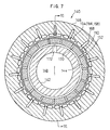
- the winding device 140 according to the second embodiment will be described below with reference to FIGS. 6 and 7.
- the winding device 140 comprises a drive shaft 142, a ring 144 of metal fixedly mounted on the drive shaft 142 and having a certain axial width, and a substantially cylindrical holder 146 rotatably mounted on the drive shaft 142 in covering relation to the ring 144, for winding the narrower web 30 therearound.
- the drive shaft 142 has an axially extending hollow space 148 defined therein.
- a seamless annular copper sheet 150 is pressed against and secured to an outer surface of the ring 144.
- a plurality of permanent magnets 154 are mounted on an inner surface 152 of the holder 146 which radially confronts the ring 144.
- the permanent magnets 154 are spaced at a constant pitch and arrayed in permanent magnet rows 156, 158.
- the permanent magnet rows 156, 158 and the annular copper sheet 150 face each other radially of the drive shaft 142.
- the holder 146 is rotatably mounted on the drive shaft 142 by a first bearing 160 and a second bearing 162, and supports on its outer surface a winding core 164 for winding the web 30 therearound.
- the winding device 140 has a cooling means 166 for cooling at least the drive shaft 142 and the holder 146.
- the cooling means 166 comprises first cooling holes 168 defined in the holder 146, second cooling holes 170 defined in the ring 144, third cooling holes 172 defined in a portion of the drive shaft 142 which is covered by the ring 144, and a suction device (not shown) connected to an end of the drive shaft 142.
- ambient cooling air is introduced via the first cooling holes 168 into the holder 146, and then introduced via the second and third cooling holes 170, 172 into the hollow space 148 in the drive shaft 142.
- the cooling means 166 thus functions to introduce cooling air from outside of the holder 146 into the holder 146 and the hollow space 148 in the drive shaft 142.
- the winding device 140 according to the second embodiment is basically constructed as described above. Operation and advantages of the winding device 140 will be described below.
- Magnetic fluxes are generated by magnetic forces of the permanent magnet rows 156, 158 disposed on the inner surface 152 of the holder 146.
- the ring 144 fixed to the drive shaft 142 rotates in unison with the drive shaft 142, and the annular copper sheet 150 pressed against the ring 144 cuts the magnetic fluxes generated between the permanent magnet rows 156, 158, generating eddy currents in the ring 144. Secondary magnetic fluxes by the eddy currents and the magnetic fluxes produced between the permanent magnet rows 156, 158 attract each other, producing a torque substantially proportional to a slipping speed, for example.
- the slipping speed represents the difference between the rotational speed of the drive shaft 142 and the rotational speed of the holder 146.
- a tension fluctuation ratio may be set to ⁇ 5 % or less. Therefore, the winding device 140 can produce large tensions easily and stably.
- any transverse displacement of the wound web or a web coil appearance defect can be reduced.
- such transverse displacement of the wound web can be reduced from a conventional value ranging from 2.0 to 5.0 mm to a value ranging from 0.5 to 1.0 mm.
- the winding device 140 is not limited to winding the photographic photosensitive webs (films), but is suitable for use in winding a wide web of paper, cloth, etc. having a relatively large thickness ranging from 50 to 300 ⁇ m and a width ranging from 15 to 70 mm.
- the winding device 140 has the cooling means 166 which functions to introduce cooling air from outside of the holder 146 into the holder 146 and the hollow space 148 in the drive shaft 142.
- the annular copper sheet 150 which is a source of heat generated when the web 30 is wound, is pressed against the ring 144 fixedly mounted on the drive shaft 142 that is a last component to be cooled by the introduced air, the holder 146 is cooled without being thermally affected.
- the cooling air which has been heated by the annular copper sheet 150 is discharged out of the winding device 140 without thermally affecting the other components. Therefore, the cooling capability of the cooling means 166 is increased to prevent the would web 30 from being unduly deformed.
- the number of permanent magnets 154 in the permanent magnet rows 156, 158 can be increased to increase the density of the magnetic fluxes generated between the permanent magnet rows 156, 158 for thereby reducing the slipping speed for obtaining certain tension and suppressing the heating of the annular copper sheet 150.
- the winding device 180 according to the third embodiment will be described below with reference to FIGS. 8 and 9.
- the winding device 180 comprises a drive shaft 182 having an axially extending hollow space 220 defined therein, a torque transmitter 184 fixedly mounted on the drive shaft 182 for transmitting a torque in response to rotation of the drive shaft 182, a pair of axially spaced supports 186, 188 fixedly mounted on the torque transmitter 184, and a holder 194 rotatably mounted on the drive shaft 182 by first and second bearings 190, 192.
- the holder 194 supports on its outer surface a winding core 224 for winding the narrower web 30.
- Each of the supports 186, 188 comprises an annular member of metal having hollow spaces 222 defined therein. Seamless annular copper sheets 196, 198 are pressed against and secured to respective outer surfaces of the supports 186, 188 remote from the torque transmitter 184.
- the holder 194 has circumferential surfaces 200, 202 on which a plurality of permanent magnets 208 are mounted by magnetic holders 204, 206. The permanent magnets 208 are spaced at a constant pitch and arrayed in permanent magnet rows 210, 212.
- annular copper sheets 196, 198 and the permanent magnet rows 210, 212 face each other radially of the drive shaft 182.
- the winding device 180 has a cooling means 214 for cooling at least the drive shaft 182 and the holder 194.
- the cooling means 214 comprises cooling holes 218 defined through the torque transmitter 184 and the drive shaft 182, and a suction device (not shown) connected to an end of the drive shaft 182.
- ambient cooling air is introduced via gaps between the copper sheets 196, 198 pressed against the supports 186, 188 and the permanent magnet rows 210, 212 and gaps between the permanent magnets 208 to the holder 194, and then via the cooling holes 218 into the hollow space 220 in the drive shaft 182.
- Ambient cooling air is also introduced via the hollow spaces 222 in the supports 186, 188 to the holder 194, and then via the cooling holes 218 into the hollow space 220 in the drive shaft 182.
- the winding device 180 according to the third embodiment is basically constructed as described above. Operation and advantages of the winding device 180 will be described below.
- the torque transmitter 184 fixedly mounted on the drive shaft 182 is rotated in unison with the drive shaft 182, and the copper sheets 196, 198 pressed against the supports 186, 188 fixedly mounted on the torque transmitter 184 cut the magnetic fluxes generated by the permanent magnets 208 of the permanent magnet rows 210, 212.
- eddy currents are generated in the copper sheets 196, 198, and secondary magnetic fluxes by the eddy currents and the magnetic fluxes produced by the permanent magnet rows 210, 212 attract each other, producing a torque substantially proportional to a slipping speed, for example.
- the drive shaft 182, the torque transmitter 184, the supports 186, 188, and the annular copper sheets 196, 198 are integrally held together, and made of metal.
- the heat generated by the annular copper sheets 196, 198 which are a heat source at the time the web is wound, can easily be transferred via the supports 186, 188 and the torque transmitter 184 to the drive shaft 182 for increased cooling efficiency.
- the two bearings 190, 192 are used in the holder 194.
- the bearings 190, 192 are degreased in a cleaning process, and then lubricated by several drops of oil whose viscosity ranges from SAE 20 through 30.
- those permanent magnets 208 whose magnetic forces are weaker and those permanent magnets 208 whose magnetic forces are stronger are alternately arranged to uniformize the strengths of the magnetic forces generated by the permanent magnet rows 210, 212. It is preferable to employ as many permanent magnets 208 as possible to provide the permanent magnet rows 210, 212.
- the magnetic forces are uniformized in balance, and the density of the magnetic fluxes is increased, so that the slipping speed can be lowered and the amount of generated heat can be reduced.
- the measuring positions were at the web coil diameter of 150 mm (- ⁇ -), the web coil diameter of 200 mm (- ⁇ -), the web coil diameter of 250 mm (- ⁇ -), and the web coil diameter of 300 mm (- ⁇ -). It can be seen from the measured results shown in FIG. 11 that the tension is substantially proportional to the slipping speed at each of the measuring positions.
- the tension was monitored for variations with time and the temperature of the holder 106 was monitored for variations with time at the web coil diameter of 200 mm.
- the slipping speed was fixed to 50 rpm.
- the measures results are shown in FIG. 12.
- the curve a (- ⁇ -) represents variations of the tension
- the curve b (- x -) represents variations of the temperature of the holder 106.
- the temperature of the holder 106 was initially about 35°C and the tension was initially 1.7 kg, and upon elapse of 20 minutes, the temperature of the holder 106 increased to about 60°C and the tension decreased to 1.4 kg.
- the tension was monitored for variations with time and the temperature of the holder 106 was monitored for variations with time at the web coil diameter of 600 mm.
- the measures results are shown in FIG. 14.
- the curve a (- ⁇ -) represents variations of the tension at a slipping speed of 150 rpm
- the curve b (- ⁇ -) represents variations of the temperature of the holder 106 at a slipping speed of 150 rpm
- the curve c (- ⁇ -) represents variations of the tension at a slipping speed of 200 rpm
- the curve d (- ⁇ -) represents variations of the temperature of the holder 106 at a slipping speed of 200 rpm.
- FIG. 14 A review of FIG. 14 indicates that at the slipping speed of 150 rpm, the temperature of the holder 106 was initially about 30°C and the tension was initially 1.4 kg, and upon elapse of 20 minutes, the temperature of the holder 106 increased only to about 37°C and the tension remained substantially constant.
- the temperature of the holder 106 was initially about 37°C and the tension was initially 1.7 kg, and upon elapse of 20 minutes, the temperature of the holder 106 increased to about 50°C and the tension dropped to 1.5 kg. These fluctuation ratios of the temperature and the tension are much smaller than those of the comparative example (no cooling effected).
- the winding device according to the present invention is capable of winding wide webs having a large thickness ranging from 100 to 150 ⁇ m, e.g., photographic photosensitive webs (films), with a low tension fluctuation ratio of ⁇ 5 % or less, while producing large tension easily and stably.
- the maintenance of the winding device according to the present invention is facilitated.
- a winding device of a web processing system comprises a drive shaft having a ring, an annular conductor pressed against and secured to an outer circumferential surface of the ring, and a holder rotatably mounted on the drive shaft in covering relation to the ring, for winding the web therearound, the holder supporting on an inner circumferential surface thereof a magnet row of a plurality of magnets, the magnet row facing the annular conductor.
- the annular conductor cuts the magnetic fluxes produced between magnet rows, generating eddy currents in the annular conductor. Secondary magnetic fluxes produced in the flange by the eddy currents and the magnetic fluxes produced between the magnet rows attract each other, producing a torque substantially proportional to a slipping speed, for example.
- a winding device of a web processing system comprises a drive shaft having a torque transmitter, a support fixed to the torque transmitter, an annular conductor pressed against and secured to an outer circumferential surface of the support, and a holder rotatably mounted on the drive shaft in covering relation to the support, for winding the web therearound, the holder supporting on an inner circumferential surface thereof a magnet row of a plurality of magnets with a magnet holder, the magnet row facing the annular conductor.
- the annular conductor cuts the magnetic fluxes produced between magnet rows, generating eddy currents in the annular conductor. Secondary magnetic fluxes produced in the flange by the eddy currents and the magnetic fluxes produced between the magnet rows attract each other, producing a torque substantially proportional to a slipping speed, for example.
- the number of magnets on the inner circumferential surface of the holder may be increased, and the magnets may be arranged in a plurality of magnet rows for changing the density of the magnetic fluxes generated between the magnet rows.
- Said magnet row comprises at least one magnet row.
- the magnets be spaced at a constant pitch on the holder.
- all the magnets may be measured for the strength of magnetic forces, and those magnets whose magnetic forces are weaker and those permanent magnets whose magnetic forces are stronger may be alternately arranged.
- a tension fluctuation ratio may be set to ⁇ 5 % or less. Therefore, the winding device can produce large tensions easily and stably.
- the nip roller pressing mechanism may comprise a cylinder for displacing the nip roller in a direction toward the side edge delivery roller or a direction away from the side edge delivery roller, and a regulator for regulating an air pressure supplied to the cylinder to control the pressure under which the nip roller is pressed against the side edge delivery roller.
- the peripheral speed of the side edge delivery roller may be higher than the peripheral speed of the rotary blade assembly by a value ranging from 0.5 % to 5 %.
- the pressure applied from the nip roller to the side edge delivery roller is adjusted to apply a predetermined tension to the side edges. Consequently, the narrower webs are prevented from suffering an error in their transverse dimensions as when the tension applied to the side edges is released or the tension applied to the side edges becomes greater than the tension applied to the narrower webs. Therefore, if the narrower webs are used as movie films or photographic negative films, then they assure high image quality.
Applications Claiming Priority (7)
| Application Number | Priority Date | Filing Date | Title |
|---|---|---|---|
| JP29242698 | 1998-10-14 | ||
| JP29242698 | 1998-10-14 | ||
| JP37599 | 1999-01-05 | ||
| JP11000375A JP2000218427A (ja) | 1998-09-25 | 1999-01-05 | ウェブ裁断装置 |
| JP22002899 | 1999-08-03 | ||
| JP22002899A JP3815924B2 (ja) | 1998-10-14 | 1999-08-03 | 巻取り装置 |
| EP19990120413 EP0994054B1 (de) | 1998-10-14 | 1999-10-13 | System zum Behandeln einer Bahn |
Related Parent Applications (1)
| Application Number | Title | Priority Date | Filing Date |
|---|---|---|---|
| EP19990120413 Division EP0994054B1 (de) | 1998-10-14 | 1999-10-13 | System zum Behandeln einer Bahn |
Publications (2)
| Publication Number | Publication Date |
|---|---|
| EP1348657A1 true EP1348657A1 (de) | 2003-10-01 |
| EP1348657B1 EP1348657B1 (de) | 2006-07-12 |
Family
ID=27274444
Family Applications (3)
| Application Number | Title | Priority Date | Filing Date |
|---|---|---|---|
| EP19990120413 Expired - Lifetime EP0994054B1 (de) | 1998-10-14 | 1999-10-13 | System zum Behandeln einer Bahn |
| EP20030011559 Expired - Lifetime EP1348657B1 (de) | 1998-10-14 | 1999-10-13 | Bahnverarbeitungssystem |
| EP20030011560 Expired - Lifetime EP1362812B1 (de) | 1998-10-14 | 1999-10-13 | Bahnverarbeitungssystem |
Family Applications Before (1)
| Application Number | Title | Priority Date | Filing Date |
|---|---|---|---|
| EP19990120413 Expired - Lifetime EP0994054B1 (de) | 1998-10-14 | 1999-10-13 | System zum Behandeln einer Bahn |
Family Applications After (1)
| Application Number | Title | Priority Date | Filing Date |
|---|---|---|---|
| EP20030011560 Expired - Lifetime EP1362812B1 (de) | 1998-10-14 | 1999-10-13 | Bahnverarbeitungssystem |
Country Status (3)
| Country | Link |
|---|---|
| US (3) | US6357691B1 (de) |
| EP (3) | EP0994054B1 (de) |
| DE (3) | DE69932364T2 (de) |
Cited By (1)
| Publication number | Priority date | Publication date | Assignee | Title |
|---|---|---|---|---|
| US7444911B2 (en) * | 2000-05-01 | 2008-11-04 | Fujifilm Corporation | Slitter blade assembly |
Families Citing this family (32)
| Publication number | Priority date | Publication date | Assignee | Title |
|---|---|---|---|---|
| US6357691B1 (en) * | 1998-10-14 | 2002-03-19 | Fuji Photo Film Co., Ltd. | Web processing system |
| CN1269622C (zh) * | 1999-02-25 | 2006-08-16 | 株式会社太平制作所 | 卷盘、层压板的卷板设备、和用于胶合板的生产方法 |
| US7163173B2 (en) * | 2000-12-22 | 2007-01-16 | Fuji Photo Film Co., Ltd. | Method of and apparatus for winding web |
| US8757533B2 (en) * | 2002-02-28 | 2014-06-24 | Kimberly-Clark Worldwide, Inc. | Center/surface rewinder and winder |
| JP4136460B2 (ja) * | 2002-05-29 | 2008-08-20 | 富士フイルム株式会社 | ウエブの加工方法及び加工装置 |
| JP4504909B2 (ja) * | 2005-11-04 | 2010-07-14 | 株式会社小森コーポレーション | リードインローラ隙間調整機構の隙間調整方法及び装置 |
| DE102007015380A1 (de) * | 2007-03-28 | 2008-10-02 | Heidelberger Druckmaschinen Ag | Elektromotorische Friktionsspindel |
| US20080295664A1 (en) * | 2007-06-01 | 2008-12-04 | Semion Stolyar | Web-slitter with electronic motor control |
| US8430351B2 (en) * | 2007-10-16 | 2013-04-30 | Gloucester Engineering Co., Inc. | Stretch film winder |
| US7810687B2 (en) * | 2008-07-15 | 2010-10-12 | Pitney Bowes Inc. | Self-aligning nip for web feeding mechanism |
| US8516936B2 (en) * | 2009-04-15 | 2013-08-27 | Nishimura Mfg. Co., Ltd | Slitter |
| EP2290628B1 (de) | 2009-08-25 | 2017-03-08 | ALDI SÜD Dienstleistungs-GmbH & Co. oHG | Verfahren zur Videoüberwachung von Räumen |
| US8616110B2 (en) * | 2010-09-01 | 2013-12-31 | Ford Global Technologies, Llc | Method and apparatus for making a fiber reinforced article |
| DE102011010378B4 (de) | 2011-02-04 | 2014-01-09 | Multivac Sepp Haggenmüller Gmbh & Co. Kg | Aufwickler zum Aufwickeln von Folienresten |
| KR101229743B1 (ko) | 2012-08-20 | 2013-02-05 | 주식회사 경민 | 제어용 롤러를 구비한 반도체 부직포 제조장치 |
| CN102825621B (zh) * | 2012-09-17 | 2015-12-02 | 苏州袭麟光电科技产业有限公司 | 一种和涂布机配套的薄膜修边收料装置 |
| JP5773511B2 (ja) * | 2013-04-25 | 2015-09-02 | ホリゾン・インターナショナル株式会社 | 打抜き機 |
| CN103587997A (zh) * | 2013-11-22 | 2014-02-19 | 山东省永信非织造材料有限公司 | 无纺布分切机张力自动控制装置 |
| WO2016103758A1 (ja) * | 2014-12-25 | 2016-06-30 | 住友化学株式会社 | セパレータ製造方法及びスリット方法 |
| US20160325449A1 (en) * | 2014-12-25 | 2016-11-10 | Sumitomo Chemical Company, Limited | Slitting apparatus and method for producing separator roll |
| KR101717392B1 (ko) * | 2014-12-25 | 2017-03-16 | 스미또모 가가꾸 가부시키가이샤 | 세퍼레이터 제조 방법 및 슬릿 방법 |
| JP6381652B2 (ja) | 2016-04-15 | 2018-08-29 | 住友化学株式会社 | 多孔質セパレータ長尺、その製造方法、捲回体及びリチウムイオン電池 |
| US10683124B2 (en) * | 2016-04-22 | 2020-06-16 | Encore Packaging Llc | Stretch wrap dispenser with cutting and gathering mechanisms |
| CN106144715A (zh) * | 2016-08-19 | 2016-11-23 | 盛威达机械(昆山)有限公司 | 预浸带分切复卷机 |
| US11655118B2 (en) * | 2017-07-20 | 2023-05-23 | Toyobo Co., Ltd. | Film roll and film bundle |
| CN108946278A (zh) * | 2018-06-04 | 2018-12-07 | 苏州古柏利电子科技有限公司 | 一种自动覆膜裁切机 |
| CN108749261A (zh) * | 2018-06-04 | 2018-11-06 | 苏州古柏利电子科技有限公司 | 一种覆膜裁切装置 |
| CN109292516A (zh) * | 2018-08-30 | 2019-02-01 | 广州倬粤动力新能源有限公司 | 板栅收卷方法 |
| CN112249786B (zh) * | 2020-11-04 | 2021-06-25 | 南京瑞泰金属材料制品有限公司 | 一种锂电池生产铜箔分切处理方法 |
| FI129445B (en) * | 2021-02-11 | 2022-02-28 | Valmet Technologies Oy | Braking of an unpowered roller in a fiber web machine, especially in a roller cutting machine |
| EP4101796B1 (de) * | 2021-06-11 | 2023-08-16 | FMS Force Measuring Systems AG | Aufwickelvorrichtung für eine längsgeschnittene materialbahn und system zum geregelten aufwickeln einer längsgeschnittenen materialbahn |
| CN113636414B (zh) * | 2021-10-13 | 2021-12-17 | 南通永辉自动化科技有限公司 | 一种基于物联网的张力可调型布匹包装装置 |
Citations (4)
| Publication number | Priority date | Publication date | Assignee | Title |
|---|---|---|---|---|
| GB2008158A (en) * | 1977-08-30 | 1979-05-31 | Kabel Teknik Ltd | Improvements in Winding Apparatus |
| US5180115A (en) * | 1989-04-27 | 1993-01-19 | E. I. Du Pont De Nemours And Company | Torque-transmission device |
| DE4223815A1 (de) * | 1992-07-20 | 1994-01-27 | Gerd Schuesler | Magnetisches Reihengetriebe |
| EP0618165A2 (de) * | 1993-03-15 | 1994-10-05 | Toray Engineering Co., Ltd. | Verfahren zur Steuerung des Antriebs einer Garnspulmaschine, und Garnspulmaschine dafür |
Family Cites Families (33)
| Publication number | Priority date | Publication date | Assignee | Title |
|---|---|---|---|---|
| NL66591C (de) * | ||||
| FR577872A (fr) | 1923-03-03 | 1924-09-12 | Marinoni Machines Et Materiel | Dispositif pour l'évacuation des rognures dans les machines munies de cisailles circulaires pour couper le papier, le carton ou autres produits en feuille |
| US1666984A (en) * | 1927-01-26 | 1928-04-24 | Louis P Willsea | Delivery mechanism |
| US2258428A (en) * | 1940-07-18 | 1941-10-07 | Certain Teed Prod Corp | Process of and apparatus for dividing a web |
| US2698359A (en) * | 1947-04-03 | 1954-12-28 | Int Electronics Co | Method and apparatus for making magnetic tape records |
| US3182924A (en) * | 1963-03-11 | 1965-05-11 | Fmc Corp | Web winding apparatus and method |
| US3536273A (en) * | 1969-02-07 | 1970-10-27 | Du Pont | Method of and apparatus for winding a web of plastic film |
| US3595495A (en) | 1969-03-17 | 1971-07-27 | Guardian Packaging Corp | Eddy current clutch actuated rewinder |
| US3573517A (en) * | 1970-03-02 | 1971-04-06 | Sargentwelch Scient Co | Magnetic drive |
| US3664115A (en) * | 1970-04-06 | 1972-05-23 | Celanese Corp | Method of making a semi-continuous filament combination yarn |
| US3650168A (en) * | 1970-09-08 | 1972-03-21 | Henry F Ruschmann | Operating upon strips of thin material |
| US3762250A (en) * | 1971-06-16 | 1973-10-02 | Du Pont | Method of and apparatus for handling material |
| US3934833A (en) | 1974-09-27 | 1976-01-27 | General Electric Company | Hysteresis clutch for film winding |
| US4109842A (en) | 1975-02-13 | 1978-08-29 | Aquilla John J | Sheet stripping device |
| US4063692A (en) * | 1976-06-11 | 1977-12-20 | Vista Developments, Inc. | Web winding apparatus |
| US4327301A (en) * | 1980-05-12 | 1982-04-27 | Dana Corporation | Magnetic clutch housing |
| DE3215204C2 (de) * | 1982-04-23 | 1985-09-12 | Erwin Kampf Gmbh & Co Maschinenfabrik, 5276 Wiehl | Aufwickelvorrichtung |
| US4905926A (en) * | 1983-10-28 | 1990-03-06 | Ncr Corporation | Frictionless journal take-up clutch |
| JPS60197555A (ja) * | 1984-03-19 | 1985-10-07 | Fuji Photo Film Co Ltd | ウエブ巻取装置のユニツト構造 |
| US4919027A (en) * | 1986-04-04 | 1990-04-24 | Littleton Industrial Consultants, Inc. | Sheet diverting and delivery system |
| BE1004362A4 (fr) * | 1989-07-17 | 1992-11-10 | Solvay | Enrouleuse multi-laize. |
| US5094708A (en) * | 1990-08-28 | 1992-03-10 | Graphic Communications, Inc. | Registration system for a continuous web |
| US5691587A (en) | 1993-05-21 | 1997-11-25 | Magna Force, Inc. | Magnetic centrifugal clutch |
| US5503349A (en) | 1993-07-09 | 1996-04-02 | Certek Corporation | Roll-stand brake |
| DE4335313A1 (de) * | 1993-10-16 | 1995-04-20 | Basf Magnetics Gmbh | Wickelvorrichtung zum parallelen Aufwickeln mehrerer Bänder |
| CA2114672C (en) * | 1993-11-12 | 1999-03-16 | Aaron U. Jones | Sawing apparatus |
| FR2727952A1 (fr) * | 1994-12-09 | 1996-06-14 | Clecim Sa | Bobineuse d'enroulement d'une bande |
| JP3560676B2 (ja) | 1995-03-23 | 2004-09-02 | 富士写真フイルム株式会社 | 裁断耳自動処理装置 |
| US5826474A (en) | 1995-04-07 | 1998-10-27 | Pitney Bowes Inc. | Trim strip deflector |
| JPH106126A (ja) | 1996-06-27 | 1998-01-13 | Sony Corp | 帯状部材の端部の切断装置 |
| US5727724A (en) * | 1996-09-17 | 1998-03-17 | Heidelberg Harris Inc. | Method and apparatus for transporting a web material |
| DE19802310C2 (de) * | 1998-01-22 | 2002-06-20 | Voith Paper Patent Gmbh | Rollenschneider für eine Materialbahn |
| US6357691B1 (en) * | 1998-10-14 | 2002-03-19 | Fuji Photo Film Co., Ltd. | Web processing system |
-
1999
- 1999-10-13 US US09/417,119 patent/US6357691B1/en not_active Expired - Fee Related
- 1999-10-13 EP EP19990120413 patent/EP0994054B1/de not_active Expired - Lifetime
- 1999-10-13 DE DE1999632364 patent/DE69932364T2/de not_active Expired - Lifetime
- 1999-10-13 EP EP20030011559 patent/EP1348657B1/de not_active Expired - Lifetime
- 1999-10-13 DE DE1999633144 patent/DE69933144T2/de not_active Expired - Lifetime
- 1999-10-13 EP EP20030011560 patent/EP1362812B1/de not_active Expired - Lifetime
- 1999-10-13 DE DE1999610933 patent/DE69910933T2/de not_active Expired - Lifetime
-
2002
- 2002-01-18 US US10/050,108 patent/US6464162B2/en not_active Expired - Fee Related
- 2002-09-03 US US10/232,534 patent/US6874396B2/en not_active Expired - Fee Related
Patent Citations (4)
| Publication number | Priority date | Publication date | Assignee | Title |
|---|---|---|---|---|
| GB2008158A (en) * | 1977-08-30 | 1979-05-31 | Kabel Teknik Ltd | Improvements in Winding Apparatus |
| US5180115A (en) * | 1989-04-27 | 1993-01-19 | E. I. Du Pont De Nemours And Company | Torque-transmission device |
| DE4223815A1 (de) * | 1992-07-20 | 1994-01-27 | Gerd Schuesler | Magnetisches Reihengetriebe |
| EP0618165A2 (de) * | 1993-03-15 | 1994-10-05 | Toray Engineering Co., Ltd. | Verfahren zur Steuerung des Antriebs einer Garnspulmaschine, und Garnspulmaschine dafür |
Cited By (1)
| Publication number | Priority date | Publication date | Assignee | Title |
|---|---|---|---|---|
| US7444911B2 (en) * | 2000-05-01 | 2008-11-04 | Fujifilm Corporation | Slitter blade assembly |
Also Published As
| Publication number | Publication date |
|---|---|
| DE69932364D1 (de) | 2006-08-24 |
| US6357691B1 (en) | 2002-03-19 |
| EP1348657B1 (de) | 2006-07-12 |
| EP0994054B1 (de) | 2003-09-03 |
| US6464162B2 (en) | 2002-10-15 |
| EP0994054A3 (de) | 2000-09-27 |
| DE69933144T2 (de) | 2006-12-21 |
| DE69910933D1 (de) | 2003-10-09 |
| DE69933144D1 (de) | 2006-10-19 |
| US20020056783A1 (en) | 2002-05-16 |
| EP1362812A1 (de) | 2003-11-19 |
| EP0994054A2 (de) | 2000-04-19 |
| US20030000360A1 (en) | 2003-01-02 |
| EP1362812B1 (de) | 2006-09-06 |
| US6874396B2 (en) | 2005-04-05 |
| DE69932364T2 (de) | 2006-11-16 |
| DE69910933T2 (de) | 2004-05-13 |
Similar Documents
| Publication | Publication Date | Title |
|---|---|---|
| EP1362812B1 (de) | Bahnverarbeitungssystem | |
| JP2011527644A5 (de) | ||
| JP2006264823A (ja) | ウェブ巻取装置及びスペーサ | |
| US6755371B2 (en) | Film winding method, film winding apparatus, and film manufacturing apparatus | |
| US6994290B2 (en) | Magnetic tape manufacturing apparatus | |
| JP3815924B2 (ja) | 巻取り装置 | |
| US4336911A (en) | Frictional tensioning device | |
| JP4066904B2 (ja) | ウェブの裁断装置 | |
| US5180115A (en) | Torque-transmission device | |
| JP3927591B2 (ja) | 巻取り装置 | |
| JP4153656B2 (ja) | フイルム巻き取り装置およびフイルム製造装置 | |
| US5123603A (en) | Multi-width winder | |
| JP2001063884A (ja) | シートロール体の製造方法及び装置。 | |
| JP3729878B2 (ja) | シート巻取装置 | |
| JP2003095500A (ja) | テープスリッタ | |
| JP2510961Y2 (ja) | ダイレクトドライブロ―ル | |
| JP3499635B2 (ja) | 帯状物の巻取り張力制御装置 | |
| GB2054536A (en) | Process and apparatus for winding webs on take-up members | |
| JP2849203B2 (ja) | 電子写真の定着装置用クリーニング装置 | |
| JP3944905B2 (ja) | 磁気テープの製造装置 | |
| JP2005119229A (ja) | コード巻取りシステム及び巻取り方法 | |
| JP2002173259A (ja) | フイルム加工装置およびその駆動方法 | |
| JP2003228823A (ja) | 磁気テープの製造方法 | |
| JPS6274857A (ja) | テ−プ巻取装置 |
Legal Events
| Date | Code | Title | Description |
|---|---|---|---|
| PUAI | Public reference made under article 153(3) epc to a published international application that has entered the european phase |
Free format text: ORIGINAL CODE: 0009012 |
|
| AC | Divisional application: reference to earlier application |
Ref document number: 0994054 Country of ref document: EP Kind code of ref document: P |
|
| AK | Designated contracting states |
Kind code of ref document: A1 Designated state(s): DE GB NL |
|
| 17P | Request for examination filed |
Effective date: 20030915 |
|
| AKX | Designation fees paid |
Designated state(s): DE GB NL |
|
| 17Q | First examination report despatched |
Effective date: 20050624 |
|
| GRAP | Despatch of communication of intention to grant a patent |
Free format text: ORIGINAL CODE: EPIDOSNIGR1 |
|
| GRAS | Grant fee paid |
Free format text: ORIGINAL CODE: EPIDOSNIGR3 |
|
| GRAA | (expected) grant |
Free format text: ORIGINAL CODE: 0009210 |
|
| AC | Divisional application: reference to earlier application |
Ref document number: 0994054 Country of ref document: EP Kind code of ref document: P |
|
| AK | Designated contracting states |
Kind code of ref document: B1 Designated state(s): DE GB NL |
|
| PG25 | Lapsed in a contracting state [announced via postgrant information from national office to epo] |
Ref country code: NL Free format text: LAPSE BECAUSE OF FAILURE TO SUBMIT A TRANSLATION OF THE DESCRIPTION OR TO PAY THE FEE WITHIN THE PRESCRIBED TIME-LIMIT Effective date: 20060712 |
|
| REG | Reference to a national code |
Ref country code: GB Ref legal event code: FG4D |
|
| REF | Corresponds to: |
Ref document number: 69932364 Country of ref document: DE Date of ref document: 20060824 Kind code of ref document: P |
|
| NLV1 | Nl: lapsed or annulled due to failure to fulfill the requirements of art. 29p and 29m of the patents act | ||
| RAP2 | Party data changed (patent owner data changed or rights of a patent transferred) |
Owner name: FUJIFILM CORPORATION |
|
| PLBE | No opposition filed within time limit |
Free format text: ORIGINAL CODE: 0009261 |
|
| STAA | Information on the status of an ep patent application or granted ep patent |
Free format text: STATUS: NO OPPOSITION FILED WITHIN TIME LIMIT |
|
| 26N | No opposition filed |
Effective date: 20070413 |
|
| PGFP | Annual fee paid to national office [announced via postgrant information from national office to epo] |
Ref country code: DE Payment date: 20100915 Year of fee payment: 12 |
|
| PGFP | Annual fee paid to national office [announced via postgrant information from national office to epo] |
Ref country code: GB Payment date: 20101013 Year of fee payment: 12 |
|
| GBPC | Gb: european patent ceased through non-payment of renewal fee |
Effective date: 20111013 |
|
| PG25 | Lapsed in a contracting state [announced via postgrant information from national office to epo] |
Ref country code: DE Free format text: LAPSE BECAUSE OF NON-PAYMENT OF DUE FEES Effective date: 20120501 |
|
| REG | Reference to a national code |
Ref country code: DE Ref legal event code: R119 Ref document number: 69932364 Country of ref document: DE Effective date: 20120501 |
|
| PG25 | Lapsed in a contracting state [announced via postgrant information from national office to epo] |
Ref country code: GB Free format text: LAPSE BECAUSE OF NON-PAYMENT OF DUE FEES Effective date: 20111013 |