EP1321417A1 - Aufzugsschacht und Verfahren zur Errichtung eines Aufzugsschachts - Google Patents
Aufzugsschacht und Verfahren zur Errichtung eines Aufzugsschachts Download PDFInfo
- Publication number
- EP1321417A1 EP1321417A1 EP02027351A EP02027351A EP1321417A1 EP 1321417 A1 EP1321417 A1 EP 1321417A1 EP 02027351 A EP02027351 A EP 02027351A EP 02027351 A EP02027351 A EP 02027351A EP 1321417 A1 EP1321417 A1 EP 1321417A1
- Authority
- EP
- European Patent Office
- Prior art keywords
- elevator shaft
- modular
- elevator
- shaft according
- guides
- Prior art date
- Legal status (The legal status is an assumption and is not a legal conclusion. Google has not performed a legal analysis and makes no representation as to the accuracy of the status listed.)
- Granted
Links
- 238000000034 method Methods 0.000 title claims description 5
- 239000004567 concrete Substances 0.000 claims abstract description 26
- 238000009415 formwork Methods 0.000 claims description 7
- 238000005266 casting Methods 0.000 claims description 4
- 230000007423 decrease Effects 0.000 claims 1
- 230000008878 coupling Effects 0.000 description 18
- 238000010168 coupling process Methods 0.000 description 18
- 238000005859 coupling reaction Methods 0.000 description 18
- 238000010276 construction Methods 0.000 description 12
- 239000004570 mortar (masonry) Substances 0.000 description 6
- 229910052751 metal Inorganic materials 0.000 description 4
- 239000002184 metal Substances 0.000 description 4
- 229910000831 Steel Inorganic materials 0.000 description 3
- 239000010959 steel Substances 0.000 description 3
- 238000009412 basement excavation Methods 0.000 description 2
- 238000005253 cladding Methods 0.000 description 2
- 238000009434 installation Methods 0.000 description 2
- 238000009413 insulation Methods 0.000 description 2
- 238000004519 manufacturing process Methods 0.000 description 2
- 230000007246 mechanism Effects 0.000 description 2
- 238000004806 packaging method and process Methods 0.000 description 2
- 238000007789 sealing Methods 0.000 description 2
- 230000003068 static effect Effects 0.000 description 2
- 230000007704 transition Effects 0.000 description 2
- 230000006978 adaptation Effects 0.000 description 1
- 229910052782 aluminium Inorganic materials 0.000 description 1
- XAGFODPZIPBFFR-UHFFFAOYSA-N aluminium Chemical compound [Al] XAGFODPZIPBFFR-UHFFFAOYSA-N 0.000 description 1
- 230000008901 benefit Effects 0.000 description 1
- 230000000295 complement effect Effects 0.000 description 1
- 239000002131 composite material Substances 0.000 description 1
- 230000001419 dependent effect Effects 0.000 description 1
- 230000005484 gravity Effects 0.000 description 1
- 239000003673 groundwater Substances 0.000 description 1
- 238000002955 isolation Methods 0.000 description 1
- 238000012423 maintenance Methods 0.000 description 1
- 239000000463 material Substances 0.000 description 1
- 238000005192 partition Methods 0.000 description 1
- 239000011505 plaster Substances 0.000 description 1
- 230000008569 process Effects 0.000 description 1
- 230000009467 reduction Effects 0.000 description 1
- 230000008439 repair process Effects 0.000 description 1
- 230000000284 resting effect Effects 0.000 description 1
- 239000000725 suspension Substances 0.000 description 1
- 238000009423 ventilation Methods 0.000 description 1
- XLYOFNOQVPJJNP-UHFFFAOYSA-N water Substances O XLYOFNOQVPJJNP-UHFFFAOYSA-N 0.000 description 1
Images




Classifications
-
- E—FIXED CONSTRUCTIONS
- E04—BUILDING
- E04F—FINISHING WORK ON BUILDINGS, e.g. STAIRS, FLOORS
- E04F17/00—Vertical ducts; Channels, e.g. for drainage
- E04F17/005—Lift shafts
Definitions
- the present invention relates to an elevator shaft according to the preamble of claim 1 and a method for Construction of an elevator shaft according to the generic term of the Claim 13.
- the utility model DE 201 05 144 U1 is a self-supporting cable elevator known, in which the leadership of the Cabins and counterweights on the shaft door front is arranged.
- it is statically self-supporting integrated front structure provided by the shaft floor extends to the shaft ceiling and at the same time one Partition between the anteroom and shaft forms.
- the Structure is a steel structure.
- the Integrated front structure has at least two shaft door modules on that vertically between a lower buffer module and an upper drive module are arranged.
- the integrated Front structure includes two continuous, modular trained, vertical, hollow pillars, the door pillars called because they define a space in which the shaft doors are located. These hollow door pillars lead the counterweights inside.
- each door pillar Guide rails attached to guide the cabin.
- This The frame forms a U-shaped structure with the door front.
- On the back of each column is at right angles to the door front another frame with rails to guide the cabin welded.
- the shaft door modules can, if different floor heights consist of a standard shaft door unit and one order-specific adaptation unit include that by means of pin attached to the guide rail frame in vertical axis are plugged together to the given To reach the height of the shaft door module.
- For repairs and Maintenance is the installation of the drive module via a Flap accessible from the anteroom.
- the Drive module are the traction sheaves, each with its own Provide drive unit.
- the hollow pillars of the landing door unit can be made of different materials, such as steel, Aluminum, concrete, plastic exist and different Have shapes.
- CH 525 833 is also a concrete structure known as an elevator shaft with two guide walls, as well as a front wall and a rear wall.
- Side walls To the Side walls are ribs with several guide surfaces executed that serve as a guide for the elevator car. These ribs are homogeneous with the wall parts and continuously connected. Are parallel to these ribs Similar guide parts exist to that in wires or Rope guided counterweight for safety reasons to offer additional guidance.
- the side walls are each on two opposite ends, top and bottom, with Centering provided.
- the modular roadway elements 10 and 20 according to FIGS. 1 and 2 basically have three walls 1, 2, 3 and at least one approximate C-shaped cross-section or floor plan.
- This C-shaped roadway elements 10 and 20 are preferred constructed so that it prefabricated road and Form door front modules and each include two integrated Cabin guides or lanes 11, 12 (FIG. 1) or 21, 22 (Fig. 2) and a door opening 13 and 23 respectively in the version 1, the corners or corner edges 14, 15th rectangular, but they can also be rounded be or other architecturally and technically meaningful Have shapes. You also don't necessarily have to be symmetrical be, as shown in Figures 1 and 2.
- the surfaces 16, 17 of the inner sides of the C-shaped roadway element can be parallel or, as shown in Fig. 1, an inner corner angle ⁇ on the inside of the shaft form, for example, greater than 90 degrees, where the walls 1, 2 thinner with increasing distance from the wall 3 can be.
- the modular roadway elements are preferably 10 and 20 prefabricated concrete modules (e.g. from poured concrete), the road elements 10 and 20 with Channels 18 or other recesses for an integrated Cabling can be provided.
- the lanes 11, 12 (Fig. 1) or 21, 22 (Fig. 2) can with a continuous Cavity 19, for example for a cable for mutual Bracing of several road elements resting on each other 10, 20. By mutual tension can be the stability of one of several modular roadway elements 10, 20 existing elevator shaft improved become.
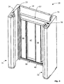
- the modular roadway element 30 includes built-in cabin guides 31, 32, in Concrete guides 33, 34 and 35, 36 for counterweights and in the concrete integrated guides 37, 38 for Landing doors. These guides are preferably directly in the Formed concrete, or for example as metal guides in poured the concrete.
- Fig. 4 shows a plan view of the elevator shaft through another C-shaped construction or module 39 can be completed peripherally where an elevator car 40 is housed with doors 41, 42, 43, 44, which is a door system form with sliding door leaves.
- the module 39 is designed statically non-load-bearing.
- At the Elevator car 40 has a carrier 45 at the top and bottom Rollers 93, 94, 95, 96 for guiding the elevator car attached.
- Fig. 3 are also four optionally pre-assembled Shaft doors 46, 47, 48, 49 shown in the Guides 37, 38 can be stored.
- the balance weight guides 33 to 36 laterally, that is left and / or right at least approximately parallel or preferably forming an inner corner angle ⁇ > 90 ° Pages 16, 17 (FIG. 1) of the C-shaped roadway element 30 and be arranged within the shaft wall projection.
- the module 39 can Buildings have a supporting function, but without that To carry elevator shaft and its elements.
- 5A and 5B show a roadway element 70, that rests on a prefabricated pit 60.
- This pit pit 60 is in the building floor slab of the building and is therefore later from outside of the elevator shaft practically invisible.
- the tub 60 serves as formwork when pouring the building floor slab.
- a possible embodiment of a pit pit 60 is in 5A, 5B and 7 are shown and performed a master module introduced as a pit
- the tub 60 preferably has a bottom 64.
- the term tub can optionally also a tub with an opening Floor or even a bottomless frame can be subsumed.
- the building floor slab is placed on a base floor (e.g. the Excavation pit floor) made, the tub 60 poured can be. Then a first prefabricated one can be placed on it the site delivered, for example C-shaped Roadway element 70 are introduced, after which further roadway elements 20 (FIG.
- Elevator support structure which is a top module (see for example Figures 8A and 8B) and stairwell platforms can carry.
- the roadway elements are preferably such dimensioned that they are the vertical forces in the Are able to accommodate elevator shaft. With these vertical forces are particularly concerned with the Dead weight of the elevator shaft and around that in the operation of the Forces occurring in the elevator.
- the pit pit 60 is brought in and on this mortar bed pushed the correct position. Then the pit pit 60 be filled with water so that they can pour themselves the building floor slab does not move. Then will around the pit pit concrete in the construction pit poured to create the building floor slab.
- the first pavement element becomes hardened 70 placed, as schematically in Figures 6 and 7 indicated by arrows. At the support point of the first Roadway element 70 on the pit pit 60 can be a thin layer of mortar can be applied.
- the road element 70 is 71 by means of a centering & positioning bolt positioned.
- the exact location in the horizontal plane will adjusted by rotation about a vertical axis 72.
- the road element in the Mortar layer lowered.
- the position of the road element can be set.
- the mortar layer at least partially the weight of all road elements wearing.
- the next following lane element is preferably after pouring the first concrete floor (1st Floor ceiling), with two centering & positioning bolts in Aligned with respect to the underlying lane element.
- the tub 60 has at least one integrated Centering & positioning bolt 71. Also points the tub screw holes 73, in which fixing screws 74 can be screwed to the roadway element 70 to attach the tub 60.
- the tub preferably has 60 an all-round sealing flange 63 to prevent groundwater seal.
- the tub 60 can also be provided with tabs 75 be that anchor the tub in the building floor slab. she however, does not have to be load-bearing for the elevator structure; the Forces are preferably applied directly over the mortar layer directed the building floor slab.
- the base module designed as a tub 60 has a small size Weight and a small volume for transport and assembly and brings a drastic reduction in construction time and the construction costs with it, in particular no special Hoist for larger loads is required. Also met such a basic module simultaneously construction and elevator functions. With conventional elevator systems, the pit pit had to be at the location of the elevator shaft to be erected Pour concrete by step by step appropriate wooden cladding was built. This process was very labor intensive and expensive. This Steps are omitted when using one according to the invention Tray 60. Tray 60 preferably consists of a CF composite.
- the tub 60 has a weight of, for example less than 100kg.
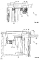
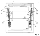
- the top element of the elevator shaft which is also Topmodul 80 8A and 8B has at least a drive 81 and several roles, for example the Rollers 91, 92, 97, 98 for the cabin side runs 82 and / or for the counterweight side strands 83 of the tragund Drive cables.
- the top module 80 on which indirectly the Elevator car 40 and at least one - not shown here - Counterweight hanging (see Fig. 8B), a kind Cover 86, which is from a flat roof 89 (building ceiling) brought here.
- top module 80 is preferably seated on an upper carriageway element 100 on. It is preferably the Top module 80 around an element prefabricated from concrete.
- This top module 80 with integrated elevator and construction functions that on the top lane and door front module 100 positioned and supported, can be factory set pre-assembled suspension and deflection pulleys (for example the rollers 91, 92, 97, 98), with a factory pre-assembled Drive unit 81 and / or with integrated Building interfaces or building interfaces for sealing and Isolation of the top building ceiling 89 may be provided.
- the Topmodul 80 can be used as internal cladding for casting the Building ceiling 89 can be used.
- top module 80 This is mounted on the shaft head and as a ceiling connection serving top module 80 is inexpensive, which the When it comes to transport and assembly, there is a great deal Occupational safety during elevator assembly, can be considered Packaging of the elevator components, for example the rolls and the drive are used and also leads on site low costs for shaft head construction.
- Top module 80 can be designed such that it is used as weather protection can be used during an installation phase.
- FIG. 9 is a role 91 and 92 for the two each Counterweights 84 or 85 carrying ropes 83 (FIG. 8B), arranged so that the projection of each hanging Rope 83 at least approximated by the center of gravity of the corresponding counterweight 84 and 85 runs.
- a Carrier 45 is present on which four rollers 93, 94, 95, 96 are rotatably arranged, in solidarity with the Move elevator car 40.
- the four rollers 93, 94, 95, 96 are preferably formed by the trapezoidal Cabin guides 11, 12 (Fig. 1), or 21, 22 (Fig. 2), or 31, 33 (Fig. 3) of the respective modular carriageway element guided.
- the preferably C-shaped roadway elements 10 (Fig. 1), 20 (Fig. 2), 70 (Fig. 6) and 100 (Fig. 8B) can also be used to carry staircase platforms, even if the complementary module 39 (FIG. 4 or FIG. 9) omitted, for example, regarding design and Load capacities free rear shaft wall area as design freedom to form for architects.
- the C-shaped Lane elements 10, 20, 70 and 100 can then "inside” and "outside” on the facade of a building, or in a Facade niches can be built in or built on.
- the modular C-shaped track elements 10, 20, 70 and 100 can be used for the direct inclusion of functional elements (e.g. functional elements of the door mechanism) become. It doesn't necessarily need to be more specific Metal frames or metal profiles.
- the roadway elements 10, 20, 70 and 100 can have so-called plaster edges in order to enable easier plastering of the shaft outer walls. Due to their modular design, there is no compensation of construction tolerances.
- the modular roadway elements 10, 20, 70 and 100 can have special recesses or fasteners for direct, frameless fastening of the door mechanism exhibit.
- the modular elevator shaft according to the invention proves to be particularly advantageous in that Wear or to support doors, or to clean and exact closure or none for fire protection requirements additional door frame is required.
- the single ones Modules or elements are light in weight and small volume, which is not only an advantage for transport and assembly involves, but in general the erection of the elevator shaft by the contracted construction company in the absence of elevator experts at the construction site, without a special one in terms of load and stroke Need to have hoist because of construction and elevator functions with the same elements or modules, even the display and controls can be pre-assembled.
- the trapezoidal ones are preferred Roads 11 and 12 (Fig. 1) cast from concrete.
- This one Roadways are only used to guide the cabin 40 they are unproblematic from a static point of view. It is possible to provide relatively thin walls 16 and 17 (Fig. 1), but then not for fastening or as load-bearing Structures should be used. You should also at Conception of the entire elevator shaft and the individual Roadway elements try to avoid sound bridges in order to enable good sound insulation.
- the horizontal Road loads due to eccentric loading of the Elevator car 40 can reach relatively high values. This horizontal loads - even with thin walls 16 and 17 (Fig. 1) - unproblematic because they are on everyone Floor can be caught by the floor ceilings.
- the Connections between the road elements and the floor slabs can either be as rigid concrete / concrete connections or in the form of elastic sound insulation elements will be realized.
- the counterweight guide for example in the form of the rails 33 and 35, could also be at least partially on the door front wall 3 be arranged.
- the carrier 45 of the cabin 40 (Fig. 9) is directly over the four upper guide rollers 93 to 95 and for example over another four lower rolls not visible in the figures a lower beam, for example, along the concrete carriageways 21, 22 (Fig. 2) performed.
- the trapezoidal design of the roadways 21, 22 there are four elongated guide levels 24, 25 and 26, 27 in Fig. 2, which extend vertically in the elevator shaft.
- the intermediate levels 28 and 29 are not used for guiding the elevator car 40, but can if necessary for other functions are used.
- the trapezoidal design of the carriageways 21, 22 is the guide the cabin 40 very stable and also usable, for example absorb vertical forces.
- the guide geometry is very exactly, because the joints and the track distance are bound to form.
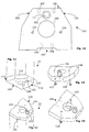
- the ends of a roadway 21, 22 (Fig. 11, 12) of a roadway element are preferably with one each directly in the concrete cast coupling piece 101 provided in FIG. 10.
- the FIGS. 11 and 12 show coupling pieces 110 and 120 on the Ends of two abutting road elements. These coupling pieces 110 and 120 comprise a centering pin 121 (FIG. 12) and a centering hole 111 (FIG. 11), which makes them automatic when installing the elevator shaft aligned with each other.
- the coupling pieces 101 are in the example shown with screwed anchorages 131, 132 and 133, 134 according to FIGS. 13 and 14, um to keep them anchored in the concrete after pouring.
- the Surfaces 112, 113, 114 and 122, 123, 124 have the same polygonal cross-sectional shape, such as the trapezoidal Roadways 11 and 12 according to FIG. 1 or 21 and 22 according to Fig. 2.
- the coupling pieces exist 110 or 120 made of metal and can therefore also be used as Serve edge protection.
- the oblique trapezoidal sides 102 and 103 in Fig. 10 correspond, for example, close an angle of minute 60 ° and max. 120 °, but preferably an angle from approx. 80 ° to approx. 100 °.
- the treads 11, 12, 21, 22 should not have grooves, shoulders or have other bumps in order to
- the coupling pieces 101 (Fig. 10), 110, 120 (Fig. 11, 12) before pouring the track elements into the mold inserted. This results in ideally level transitions from the cast concrete guide surfaces to the coupling pieces.
- There are coupling pieces lying on top of each other neighboring lane elements are precisely centered on each other are perfectly aligned when assembled, clear lanes.
- the coupling pieces 101 preferably each have at least one a recess 104 and / or a (threaded) bore 105, 106 on the mutual fixation of two on each other stationary road elements, for example with connecting straps, serve.
- (threaded) holes can 107, 108 are present, with which a twist or Shifting the when the roadway elements are cast into the Casting inserted coupling pieces is prevented.
- the roadway elements 10, 20, 30, 70 and 100 are preferred with a continuous cavity 19 and the coupling pieces 101 provided with openings 109 through which such Cavities 19 and openings 109 for example at least one To be able to pull cables through.
- the roadway elements 10, 20, 30, 70 and 100 are preferred provided with lanes 11, 12 or 21, 22 or 31, 32, the at least approximately trapezoidal cross-section have, wherein the coupling pieces 101 with plate the same trapezoidal cross section can.
- the sloping trapezoidal sides of the roadways can also serve as a guide for rollers 93, 94, 95, 96, which are located on a carrier 45, which is on the elevator car 40 is attached.
- the roles 93, 94, 95, 96 can also be otherwise connected to the elevator car 40.
- FIG. 15 Two other embodiments of the invention are in Described in connection with Figures 15 and 16.
- a modular roadway element 140 is shown, which is shown in FIG lower area has a kind of all-round ledge 141.
- This ledge 141 can, for example, formwork 142 for the Support casting a floor slab, as in Figure 15 partially shown.
- Another variant is in the Sectional view shown in Figure 16.
- the road element 150 has a recess 151, which as a means for Recording formwork 152 can serve as on the left Side of the figure indicated.
- the means 141 and 151 can under certain circumstances, also carry the ceiling directly.
- the elevator shaft with prefabricated modular track elements (e.g. from roadway elements 10, 20) be an at least approximately C-shaped cross section exhibit.
- a preferably modular elevator shaft lanes 11, 12 or 21, 22 or 31, 32 which at least one have approximately trapezoidal cross-section, the sloping trapezoidal sides of the carriageway as a guide serve for roles 93, 94, 95, 96 that adhere to at least a carrier 45 are located on the elevator car 40th is attached.
- a modular one Elevator shaft with at least two prefabricated modular Road elements (e.g. from road elements 10, 20) be formed, the roadways 11, 12, 21, 22 for the Elevator car 40 include such that at least on the upper end of a lower lane of a lane element a coupling piece 120 (Fig. 12) is fixed, and that at least at the bottom of an upper lane of a next lane element, a further coupling piece 110 (FIG. 11) is fixed, with both coupling pieces 110, 120 are configured to include at least one for the Guiding the elevator car 40 provided area aligned transition between these two lanes too form.
- a coupling piece 120 (Fig. 12) is fixed, and that at least at the bottom of an upper lane of a next lane element, a further coupling piece 110 (FIG. 11) is fixed, with both coupling pieces 110, 120 are configured to include at least one for the Guiding the elevator car 40 provided area aligned transition between these two lanes too form.
- the elevator shaft can at least partially on a concrete building floor slab rest, in which a tub 60 is embedded, which as Formwork is used when pouring the building floor slab.
- the Manhole head of an elevator shaft as a modular prefabricated Top module 80 may be formed from concrete.
- inventive designs of such an elevator shaft prove to be particularly inexpensive at Manufacturing in the factory as well as for transport and assembly. she ensure increased occupational safety during lift assembly and enable the use of a Top module as "packaging" of the elevator components, for example of the units with rollers and drive.
Landscapes
- Engineering & Computer Science (AREA)
- Architecture (AREA)
- Civil Engineering (AREA)
- Structural Engineering (AREA)
- Types And Forms Of Lifts (AREA)
- Lift-Guide Devices, And Elevator Ropes And Cables (AREA)
Abstract
Description
- Fig. 1 und 2
- schematische, perspektivische Darstellungen von zwei Fahrbahnelementen nach einer ersten Ausführung der Erfindung, die aufeinander montiert werden,
- Fig. 3
- eine perspektivische Darstellung einer zweiten Ausführung eines solchen Fahrbahnelements, das auch Fahrbahn- und Türfrontmodul genannt wird,
- Fig. 4
- eine schematische Querschnittdarstellung eines derartigen Fahrbahnelements,
- Fig. 5A
- eine schematische perspektivische Darstellung eines Fahrbahnelements, das auf einer in eine Ge- bäudebodenplatte eingegossenen Wanne ruht,
- Fig. 5B
- eine vergrösserte Detailansicht der Fig. 5A,
- Fig. 6
- eine perspektivische Darstellung eines Fahrbahnelements, bevor es auf eine in der Gebäudebodenplatte eingegossene Wanne nach der Erfindung abgesenkt wird,
- Fig. 7
- einige Details einer solchen Wanne,
- Fig. 8A
- eine schematische Seitenansicht eines Ausschnitts eines erfindungsgemässen Topmoduls,
- Fig. 8B
- eine schematische Seitenansicht des erfindungsgemässen Topmoduls nach Fig. 8A,
- Fig. 9
- eine schematische Querschnittdarstellung eines derartigen Topmoduls,
- Fig. 10
- eine Querschnittdarstellung eines Kopplungsstücks für erfindungsgemässe Fahrbahnelemente,
- Fig. 11 und 12
- eine perspektivische Darstellung von zwei aufeinander platzierbaren Fahrbahnelementen mit je einem Kopplungsstück an deren Enden,
- Fig. 13 und 14
- Detailansichten der Kopplungselemente vor dem Eingiessen,
- Fig. 15
- eine perspektivische Darstellung eines weiteren Fahrbahnelements, das Mittel zum Stützen einer Schalung aufweist, und
- Fig. 16
- eine schematische Schnittdarstellung eines weiteren Fahrbahnelements, das Mittel zum Stützen einer Schalung aufweist.
Claims (13)
- Modular aufgebauter Aufzugsschacht mit zwei Seitenwänden (1, 2) mit Führungen für eine Aufzugskabine, dadurch gekennzeichnet, dass der Aufzugsschacht mit wenigstens einem vorfabrizierten modularen Fahrbahnelement (10; 20; 30; 70; 100) ausgebildet ist, das einen zumindest angenähert C-förmigen Querschnitt aufweist, dass die zwei Seitenwände (1, 2) je eine integrierte Fahrbahn (11, 12; 21, 22) für die Aufzugskabine (40) umfassen, und dass die zwei Seitenwände (1, 2) derart durch eine mittlere dritte Wand (3) verbunden sind, dass die drei verbundenen Wände (1, 2, 3) den C-förmigen Querschnitt ergeben, und wobei die dritte Wand (3) mit einer Türöffnung (13; 23) versehen ist.
- Aufzugsschacht nach Anspruch 1, dadurch gekennzeichnet, dass das modulare Fahrbahnelement (10; 20; 30) einstückig als Betonstruktur vorfabriziert ist und in die Betonstruktur integrierte Kabinenführungen (31, 32), und/oder in die Betonstruktur integrierte Führungen (33, 34; 35, 36) für Ausgleichgewichte, und/oder im Bereich der Türöffnung (13; 23) in die Betonstruktur integrierte Führungen (37, 38) für Schachttüren aufweist.
- Aufzugsschacht nach Anspruch 2, dadurch gekennzeichnet, dass sich sowohl die integrierten Kabinenführungen (31, 32) als auch die Führungen (33, 34; 35, 36) für die Ausgleichgewichte an innenseitigen Flächen (16, 17) der zwei Seitenwände (1, 2) des modularen Fahrbahnelements (10; 20; 30) befinden.
- Aufzugsschacht nach einem der Ansprüche 2 bis 3, dadurch gekennzeichnet, dass innenseitige Flächen (16, 17) der Seitenwände (1, 2) des modularen Fahrbahnelements (10; 20; 30), zumindest im Bereich, in dem sich die Führungen (33, 34; 35, 36) für die Ausgleichgewichte der Aufzugskabine (40) befinden, einen inneren Eckwinkel (α) bilden, der grösser ist als 90 Grad und somit die Dicke der Seitenwände (1, 2) mit zunehmendem Abstand von der dritten Wand (3) abnimmt.
- Aufzugsschacht nach einem der Ansprüche 1 bis 4, dadurch gekennzeichnet, dass das modulare Fahrbahnelement (10; 20; 30) mit parallel zu den Kabinenführungen verlaufenden Kanälen (18), vorzugsweise für eine integrierte Verkabelung, versehen ist.
- Aufzugsschacht nach einem der Ansprüche 1 bis 5, dadurch gekennzeichnet, dass der Aufzugschacht mehrere aufeinander geschichtete modulare Fahrbahnelemente (10; 20; 30) umfasst, wobei die modulareren Fahrbahnelemente (10; 20; 30) mit einem durchgehenden Hohlraum (19), vorzugsweise für ein Kabel zum vorgespannten Verbinden der modularen Fahrbahnelemente (10; 20; 30), versehen sind.
- Aufzugsschacht nach einem der Ansprüche 1 bis 6, dadurch gekennzeichnet, dass das modular Fahrbahnelement (10; 20; 30) mit Fahrbahnen (11, 12; 21, 22) versehen ist, die einen zumindest angenähert trapezförmigen Querschnitt aufweisen, und dass die Fahrbahnen (11, 12; 21, 22) schräg stehende Trapez-Seiten (24, 25, 26, 27) aufweisen, die als Führung für Rollen (93, 94, 95, 96) dienen, die mit der Aufzugskabine (40) verbunden sind.
- Aufzugsschacht nach einem der Ansprüche 1 bis 7, dadurch gekennzeichnet, dass das modulare Fahrbahnelement (10; 20; 30; 70; 100) derart statisch dimensioniert ist, dass es als Tragstruktur dient um vertikale Kräfte des Aufzugsschachtes, insbesondere das Eigengewicht des Aufzugsschachtes und im Betrieb des Aufzugs auftretende Kräfte, aufzunehmen.
- Aufzugsschacht nach einem der Ansprüche 1 bis 8, dadurch gekennzeichnet, dass das modulare Fahrbahnelement (10; 20; 30; 70; 100) derart dimensioniert ist, dass es ein Treppenhauspodest und/oder ein Topmodul (80) tragen kann.
- Aufzugsschacht nach einem der Ansprüche 1 bis 9, dadurch gekennzeichnet, dass gegenüber der mittleren dritten Wand (3) ein Modul (39) angebracht ist, um den Aufzugsschacht zu schliessen, wobei das Modul (39) vorzugsweise als nichttragendes Element des Aufzugschachtes ausgeführt ist.
- Aufzugsschacht nach einem der Ansprüche 1 bis 10, dadurch gekennzeichnet, dass das modulare Fahrbahnelement (10; 20; 30) ab Werk mit integrierten Schachttüren (46, 47, 48, 49) ausgestattet ist.
- Aufzugsschacht nach einem der Ansprüche 1 bis 11, dadurch gekennzeichnet, dass mindestens eines der modularen Fahrbahnelement (140; 150) Mittel (141; 151) aufweist, die geeignet sind, um eine Schalung (142; 152) für das Giessen einer Geschossdecke abzustützen."
- Verfahren zur Errichtung eines Aufzugsschachts nach einem der Ansprüche 1 bis 11, dadurch gekennzeichnet,dass auf einer am Ort eines zu errichtenden Gebäudes hergestellten Gebäudebodenplatte ein erstes vorfabriziertes modulares Fahrbahnelement (10) eingebracht wird,dass das vorfabrizierte modulare Fahrbahnelement (10) horizontal und vertikale ausgerichtet wird, unddass danach mindestens ein weiteres modulares Fahrbahnelement (20) auf dem ersten vorfabrizierten modularen Fahrbahnelement (10) positioniert wird, wobei der Aufzugsschacht mit dem Gebäude wachsend montiert wird.
Priority Applications (1)
| Application Number | Priority Date | Filing Date | Title |
|---|---|---|---|
| EP02027351A EP1321417B1 (de) | 2001-12-21 | 2002-12-07 | Aufzugsschacht und Verfahren zur Errichtung eines Aufzugsschachts |
Applications Claiming Priority (3)
| Application Number | Priority Date | Filing Date | Title |
|---|---|---|---|
| EP01811255 | 2001-12-21 | ||
| EP01811255 | 2001-12-21 | ||
| EP02027351A EP1321417B1 (de) | 2001-12-21 | 2002-12-07 | Aufzugsschacht und Verfahren zur Errichtung eines Aufzugsschachts |
Publications (2)
| Publication Number | Publication Date |
|---|---|
| EP1321417A1 true EP1321417A1 (de) | 2003-06-25 |
| EP1321417B1 EP1321417B1 (de) | 2007-07-11 |
Family
ID=38289100
Family Applications (1)
| Application Number | Title | Priority Date | Filing Date |
|---|---|---|---|
| EP02027351A Expired - Lifetime EP1321417B1 (de) | 2001-12-21 | 2002-12-07 | Aufzugsschacht und Verfahren zur Errichtung eines Aufzugsschachts |
Country Status (5)
| Country | Link |
|---|---|
| EP (1) | EP1321417B1 (de) |
| AT (1) | ATE366707T1 (de) |
| DE (1) | DE50210450D1 (de) |
| ES (1) | ES2290236T3 (de) |
| PT (1) | PT1321417E (de) |
Cited By (8)
| Publication number | Priority date | Publication date | Assignee | Title |
|---|---|---|---|---|
| GB2473026A (en) * | 2009-08-26 | 2011-03-02 | Waycon Precast Ltd | Lift shaft assembly comprising pre-fabricated concrete sections |
| US20120168263A1 (en) * | 2011-01-05 | 2012-07-05 | Alois Dominick J | Elevator liner apparatus and utilization method thereof |
| CN114592708A (zh) * | 2021-04-29 | 2022-06-07 | 深圳市凌盛电子有限公司 | 小高层建筑电梯改建过程的无遮挡式防掉落外墙施工组件 |
| CN114922385A (zh) * | 2022-07-18 | 2022-08-19 | 山东天齐置业集团股份有限公司 | 柱式电梯导轨固定结构及施工方法 |
| CN115095106A (zh) * | 2022-05-31 | 2022-09-23 | 上海宝冶集团有限公司 | 一种电梯井道结构及其施工方法 |
| EP4083344A1 (de) * | 2021-04-30 | 2022-11-02 | Manfred Greschbach | Schachtelement für eine aufzugsanlage sowie verfahren zum herstellen eines schachts |
| US20230068973A1 (en) * | 2020-11-10 | 2023-03-02 | Iavilaer Proprietary Limited | Construction of a building |
| CN116816033A (zh) * | 2022-03-17 | 2023-09-29 | 联知(浙江)实业有限公司 | 相邻两根烟管在建筑物上的安装方法及建筑物 |
Families Citing this family (1)
| Publication number | Priority date | Publication date | Assignee | Title |
|---|---|---|---|---|
| CN109537849B (zh) * | 2018-11-16 | 2020-10-20 | 立达博仕电梯(苏州)有限公司 | 一种加装电梯井道支撑架 |
Citations (6)
| Publication number | Priority date | Publication date | Assignee | Title |
|---|---|---|---|---|
| DE2054936A1 (de) * | 1969-11-11 | 1971-05-27 | R Stahl Aufzuge GmbH, 7000 Stutt gart | Aufzugsschacht |
| DE2210631A1 (de) * | 1972-03-06 | 1973-09-20 | Haushahn Fa C | Aufzug fuer hochbauten |
| GB1459537A (en) * | 1974-11-21 | 1976-12-22 | Maquinaria Y Utiles Para La Co | Elevator |
| DE2755267A1 (de) * | 1977-12-12 | 1979-06-13 | Dieter Brodthage | Vorrichtung zur herstellung von aufzugschachtbausteinen |
| WO1999064338A1 (de) * | 1998-06-10 | 1999-12-16 | Zünd Ag | Führungsvorrichtung für aufzug |
| DE20105144U1 (de) * | 2001-03-24 | 2001-07-12 | Müller, Wolfgang T., 78315 Radolfzell | Selbsttragender Seilaufzug mit Kabinen- und Gegengewichtsführung in der Schachttürfront |
-
2002
- 2002-12-07 ES ES02027351T patent/ES2290236T3/es not_active Expired - Lifetime
- 2002-12-07 PT PT02027351T patent/PT1321417E/pt unknown
- 2002-12-07 DE DE50210450T patent/DE50210450D1/de not_active Expired - Lifetime
- 2002-12-07 EP EP02027351A patent/EP1321417B1/de not_active Expired - Lifetime
- 2002-12-07 AT AT02027351T patent/ATE366707T1/de not_active IP Right Cessation
Patent Citations (6)
| Publication number | Priority date | Publication date | Assignee | Title |
|---|---|---|---|---|
| DE2054936A1 (de) * | 1969-11-11 | 1971-05-27 | R Stahl Aufzuge GmbH, 7000 Stutt gart | Aufzugsschacht |
| DE2210631A1 (de) * | 1972-03-06 | 1973-09-20 | Haushahn Fa C | Aufzug fuer hochbauten |
| GB1459537A (en) * | 1974-11-21 | 1976-12-22 | Maquinaria Y Utiles Para La Co | Elevator |
| DE2755267A1 (de) * | 1977-12-12 | 1979-06-13 | Dieter Brodthage | Vorrichtung zur herstellung von aufzugschachtbausteinen |
| WO1999064338A1 (de) * | 1998-06-10 | 1999-12-16 | Zünd Ag | Führungsvorrichtung für aufzug |
| DE20105144U1 (de) * | 2001-03-24 | 2001-07-12 | Müller, Wolfgang T., 78315 Radolfzell | Selbsttragender Seilaufzug mit Kabinen- und Gegengewichtsführung in der Schachttürfront |
Cited By (11)
| Publication number | Priority date | Publication date | Assignee | Title |
|---|---|---|---|---|
| GB2473026A (en) * | 2009-08-26 | 2011-03-02 | Waycon Precast Ltd | Lift shaft assembly comprising pre-fabricated concrete sections |
| US20120168263A1 (en) * | 2011-01-05 | 2012-07-05 | Alois Dominick J | Elevator liner apparatus and utilization method thereof |
| WO2012094509A3 (en) * | 2011-01-05 | 2014-04-10 | Alois Dominick J | Elevator liner apparatus and utilization method thereof |
| US8800725B2 (en) | 2011-01-05 | 2014-08-12 | Dominick J. Alois | Elevator liner apparatus and utilization method thereof |
| US20230068973A1 (en) * | 2020-11-10 | 2023-03-02 | Iavilaer Proprietary Limited | Construction of a building |
| CN114592708A (zh) * | 2021-04-29 | 2022-06-07 | 深圳市凌盛电子有限公司 | 小高层建筑电梯改建过程的无遮挡式防掉落外墙施工组件 |
| EP4083344A1 (de) * | 2021-04-30 | 2022-11-02 | Manfred Greschbach | Schachtelement für eine aufzugsanlage sowie verfahren zum herstellen eines schachts |
| CN116816033A (zh) * | 2022-03-17 | 2023-09-29 | 联知(浙江)实业有限公司 | 相邻两根烟管在建筑物上的安装方法及建筑物 |
| CN115095106A (zh) * | 2022-05-31 | 2022-09-23 | 上海宝冶集团有限公司 | 一种电梯井道结构及其施工方法 |
| CN115095106B (zh) * | 2022-05-31 | 2024-01-30 | 上海宝冶集团有限公司 | 一种电梯井道结构及其施工方法 |
| CN114922385A (zh) * | 2022-07-18 | 2022-08-19 | 山东天齐置业集团股份有限公司 | 柱式电梯导轨固定结构及施工方法 |
Also Published As
| Publication number | Publication date |
|---|---|
| DE50210450D1 (de) | 2007-08-23 |
| EP1321417B1 (de) | 2007-07-11 |
| ES2290236T3 (es) | 2008-02-16 |
| ATE366707T1 (de) | 2007-08-15 |
| PT1321417E (pt) | 2007-09-12 |
Similar Documents
| Publication | Publication Date | Title |
|---|---|---|
| EP0865540B1 (de) | Fertigbausatz zur erstellung eines veränderbaren bahnsteigs | |
| EP3712355B1 (de) | Verfahren zum nachrüsten eines gebäudes mit einer aufzugsanlage und bauteilsatz zur durchführung des verfahrens | |
| EP3315448B1 (de) | Aufzugsanlage | |
| EP1108828B1 (de) | Aufzugschacht | |
| EP1321417B1 (de) | Aufzugsschacht und Verfahren zur Errichtung eines Aufzugsschachts | |
| DE20002775U1 (de) | Aufzugs-Treppenhausmodul mit variablen Abmessungen | |
| EP0350525B1 (de) | Verfahren zur Herstellung von Bauwerkswänden und Schalungssystem | |
| EP1321418B1 (de) | Aufzugsschacht | |
| DE3714053C2 (de) | Aufzug für Personentransport | |
| EP1321419A1 (de) | Antriebsmodul für modulierbaren Aufzugsschacht | |
| EP1321420A1 (de) | Schachtsmodul für Aufzug | |
| EP1321421A1 (de) | Schachtgrubenwanne als Basismodul für einen Aufzugsschacht | |
| DE19814639C2 (de) | Aufzugsanlage und Verfahren zu deren Anbindung an das Treppenhaus eines bestehenden, in Plattenbauweise hergestellten Gebäudes | |
| DE20300662U1 (de) | Baukonstruktion zur nachträglichen Anbindung eines Außenaufzuges an ein Treppenhaus eines mehrgeschossigen Gebäudes | |
| EP1380532B1 (de) | Verfahren zum nachträglichen Einbau eines Personenaufzugs | |
| WO2003102308A1 (de) | Fertigteil für fahrbahn-, brücken- oder stützmauerbauten und verfahren zu seiner herstellung und befestigung | |
| DE19954649C2 (de) | Verfahren und Vorrichtung zur nachträglichen Montage eines vorgefertigten Aufzugschachtgerüstes an einem Gebäude | |
| DE29507126U1 (de) | Nachträglich anbaubarer Balkon oder Wintergarten | |
| DE29923649U1 (de) | Fertighaussystem | |
| EP0965702A1 (de) | Vorgefertigte Wandelelemente im Verbundsystem-Holzspanbeton-Holzfachwerk | |
| DE2806175A1 (de) | Schwimmbad | |
| DE4423423A1 (de) | Verfahren zur Herstellung einer Wohneinheit - Fertighaus - sowie Bodenrahmen dazu | |
| EP1707674A2 (de) | Bahnsteig mit Überdachung | |
| DE102021117834A1 (de) | Hebeplattform sowie Verfahren zur Montage oder zum Entfernen einer Wohneinheit in einer Haupttragstruktur eines Gebäudes | |
| DE2750931A1 (de) | Fertigteil-bausatz fuer gebaeudewaende oder fassadenaufhaengungen |
Legal Events
| Date | Code | Title | Description |
|---|---|---|---|
| PUAI | Public reference made under article 153(3) epc to a published international application that has entered the european phase |
Free format text: ORIGINAL CODE: 0009012 |
|
| AK | Designated contracting states |
Designated state(s): AT BE BG CH CY CZ DE DK EE ES FI FR GB GR IE IT LI LU MC NL PT SE SI SK TR |
|
| AX | Request for extension of the european patent |
Extension state: AL LT LV MK RO |
|
| 17P | Request for examination filed |
Effective date: 20031203 |
|
| AKX | Designation fees paid |
Designated state(s): AT BE BG CH CY CZ DE DK EE ES FI FR GB GR IE IT LI LU MC NL PT SE SI SK TR |
|
| 17Q | First examination report despatched |
Effective date: 20040906 |
|
| GRAP | Despatch of communication of intention to grant a patent |
Free format text: ORIGINAL CODE: EPIDOSNIGR1 |
|
| GRAS | Grant fee paid |
Free format text: ORIGINAL CODE: EPIDOSNIGR3 |
|
| GRAA | (expected) grant |
Free format text: ORIGINAL CODE: 0009210 |
|
| AK | Designated contracting states |
Kind code of ref document: B1 Designated state(s): AT BE BG CH CY CZ DE DK EE ES FI FR GB GR IE IT LI LU MC NL PT SE SI SK TR |
|
| REG | Reference to a national code |
Ref country code: GB Ref legal event code: FG4D Free format text: NOT ENGLISH |
|
| RIN1 | Information on inventor provided before grant (corrected) |
Inventor name: KOCHER, JOHANNES, MASCH. ING. HTL |
|
| REG | Reference to a national code |
Ref country code: CH Ref legal event code: EP |
|
| REF | Corresponds to: |
Ref document number: 50210450 Country of ref document: DE Date of ref document: 20070823 Kind code of ref document: P |
|
| REG | Reference to a national code |
Ref country code: IE Ref legal event code: FG4D Free format text: LANGUAGE OF EP DOCUMENT: GERMAN |
|
| GBT | Gb: translation of ep patent filed (gb section 77(6)(a)/1977) |
Effective date: 20070822 |
|
| REG | Reference to a national code |
Ref country code: PT Ref legal event code: SC4A Free format text: AVAILABILITY OF NATIONAL TRANSLATION Effective date: 20070830 |
|
| ET | Fr: translation filed | ||
| PG25 | Lapsed in a contracting state [announced via postgrant information from national office to epo] |
Ref country code: NL Free format text: LAPSE BECAUSE OF FAILURE TO SUBMIT A TRANSLATION OF THE DESCRIPTION OR TO PAY THE FEE WITHIN THE PRESCRIBED TIME-LIMIT Effective date: 20070711 Ref country code: BG Free format text: LAPSE BECAUSE OF FAILURE TO SUBMIT A TRANSLATION OF THE DESCRIPTION OR TO PAY THE FEE WITHIN THE PRESCRIBED TIME-LIMIT Effective date: 20071011 |
|
| NLV1 | Nl: lapsed or annulled due to failure to fulfill the requirements of art. 29p and 29m of the patents act | ||
| REG | Reference to a national code |
Ref country code: ES Ref legal event code: FG2A Ref document number: 2290236 Country of ref document: ES Kind code of ref document: T3 |
|
| REG | Reference to a national code |
Ref country code: IE Ref legal event code: FD4D |
|
| PG25 | Lapsed in a contracting state [announced via postgrant information from national office to epo] |
Ref country code: GR Free format text: LAPSE BECAUSE OF FAILURE TO SUBMIT A TRANSLATION OF THE DESCRIPTION OR TO PAY THE FEE WITHIN THE PRESCRIBED TIME-LIMIT Effective date: 20071012 Ref country code: DK Free format text: LAPSE BECAUSE OF FAILURE TO SUBMIT A TRANSLATION OF THE DESCRIPTION OR TO PAY THE FEE WITHIN THE PRESCRIBED TIME-LIMIT Effective date: 20070711 |
|
| PLBE | No opposition filed within time limit |
Free format text: ORIGINAL CODE: 0009261 |
|
| STAA | Information on the status of an ep patent application or granted ep patent |
Free format text: STATUS: NO OPPOSITION FILED WITHIN TIME LIMIT |
|
| PG25 | Lapsed in a contracting state [announced via postgrant information from national office to epo] |
Ref country code: IE Free format text: LAPSE BECAUSE OF FAILURE TO SUBMIT A TRANSLATION OF THE DESCRIPTION OR TO PAY THE FEE WITHIN THE PRESCRIBED TIME-LIMIT Effective date: 20070711 Ref country code: SK Free format text: LAPSE BECAUSE OF FAILURE TO SUBMIT A TRANSLATION OF THE DESCRIPTION OR TO PAY THE FEE WITHIN THE PRESCRIBED TIME-LIMIT Effective date: 20070711 Ref country code: CZ Free format text: LAPSE BECAUSE OF FAILURE TO SUBMIT A TRANSLATION OF THE DESCRIPTION OR TO PAY THE FEE WITHIN THE PRESCRIBED TIME-LIMIT Effective date: 20070711 |
|
| 26N | No opposition filed |
Effective date: 20080414 |
|
| BERE | Be: lapsed |
Owner name: INVENTIO A.G. Effective date: 20071231 |
|
| PG25 | Lapsed in a contracting state [announced via postgrant information from national office to epo] |
Ref country code: SE Free format text: LAPSE BECAUSE OF FAILURE TO SUBMIT A TRANSLATION OF THE DESCRIPTION OR TO PAY THE FEE WITHIN THE PRESCRIBED TIME-LIMIT Effective date: 20071011 |
|
| PG25 | Lapsed in a contracting state [announced via postgrant information from national office to epo] |
Ref country code: MC Free format text: LAPSE BECAUSE OF NON-PAYMENT OF DUE FEES Effective date: 20071231 |
|
| PG25 | Lapsed in a contracting state [announced via postgrant information from national office to epo] |
Ref country code: BE Free format text: LAPSE BECAUSE OF NON-PAYMENT OF DUE FEES Effective date: 20071231 |
|
| PG25 | Lapsed in a contracting state [announced via postgrant information from national office to epo] |
Ref country code: EE Free format text: LAPSE BECAUSE OF FAILURE TO SUBMIT A TRANSLATION OF THE DESCRIPTION OR TO PAY THE FEE WITHIN THE PRESCRIBED TIME-LIMIT Effective date: 20070711 |
|
| PG25 | Lapsed in a contracting state [announced via postgrant information from national office to epo] |
Ref country code: AT Free format text: LAPSE BECAUSE OF NON-PAYMENT OF DUE FEES Effective date: 20071207 |
|
| PG25 | Lapsed in a contracting state [announced via postgrant information from national office to epo] |
Ref country code: SI Free format text: LAPSE BECAUSE OF FAILURE TO SUBMIT A TRANSLATION OF THE DESCRIPTION OR TO PAY THE FEE WITHIN THE PRESCRIBED TIME-LIMIT Effective date: 20070711 |
|
| PGFP | Annual fee paid to national office [announced via postgrant information from national office to epo] |
Ref country code: CH Payment date: 20090317 Year of fee payment: 7 |
|
| PG25 | Lapsed in a contracting state [announced via postgrant information from national office to epo] |
Ref country code: CY Free format text: LAPSE BECAUSE OF FAILURE TO SUBMIT A TRANSLATION OF THE DESCRIPTION OR TO PAY THE FEE WITHIN THE PRESCRIBED TIME-LIMIT Effective date: 20070711 |
|
| PG25 | Lapsed in a contracting state [announced via postgrant information from national office to epo] |
Ref country code: LU Free format text: LAPSE BECAUSE OF NON-PAYMENT OF DUE FEES Effective date: 20071207 |
|
| PGFP | Annual fee paid to national office [announced via postgrant information from national office to epo] |
Ref country code: PT Payment date: 20091123 Year of fee payment: 8 |
|
| REG | Reference to a national code |
Ref country code: CH Ref legal event code: PL |
|
| PG25 | Lapsed in a contracting state [announced via postgrant information from national office to epo] |
Ref country code: LI Free format text: LAPSE BECAUSE OF NON-PAYMENT OF DUE FEES Effective date: 20091231 Ref country code: CH Free format text: LAPSE BECAUSE OF NON-PAYMENT OF DUE FEES Effective date: 20091231 |
|
| PGFP | Annual fee paid to national office [announced via postgrant information from national office to epo] |
Ref country code: TR Payment date: 20101122 Year of fee payment: 9 |
|
| REG | Reference to a national code |
Ref country code: PT Ref legal event code: MM4A Free format text: LAPSE DUE TO NON-PAYMENT OF FEES Effective date: 20110607 |
|
| PG25 | Lapsed in a contracting state [announced via postgrant information from national office to epo] |
Ref country code: PT Free format text: LAPSE BECAUSE OF NON-PAYMENT OF DUE FEES Effective date: 20110607 |
|
| PGFP | Annual fee paid to national office [announced via postgrant information from national office to epo] |
Ref country code: FI Payment date: 20111214 Year of fee payment: 10 Ref country code: ES Payment date: 20111227 Year of fee payment: 10 |
|
| PGFP | Annual fee paid to national office [announced via postgrant information from national office to epo] |
Ref country code: IT Payment date: 20111228 Year of fee payment: 10 |
|
| PG25 | Lapsed in a contracting state [announced via postgrant information from national office to epo] |
Ref country code: FI Free format text: LAPSE BECAUSE OF NON-PAYMENT OF DUE FEES Effective date: 20121207 |
|
| PG25 | Lapsed in a contracting state [announced via postgrant information from national office to epo] |
Ref country code: IT Free format text: LAPSE BECAUSE OF NON-PAYMENT OF DUE FEES Effective date: 20121207 |
|
| PG25 | Lapsed in a contracting state [announced via postgrant information from national office to epo] |
Ref country code: TR Free format text: LAPSE BECAUSE OF NON-PAYMENT OF DUE FEES Effective date: 20121207 |
|
| REG | Reference to a national code |
Ref country code: ES Ref legal event code: FD2A Effective date: 20140527 |
|
| PG25 | Lapsed in a contracting state [announced via postgrant information from national office to epo] |
Ref country code: ES Free format text: LAPSE BECAUSE OF NON-PAYMENT OF DUE FEES Effective date: 20121208 |
|
| REG | Reference to a national code |
Ref country code: FR Ref legal event code: PLFP Year of fee payment: 14 |
|
| REG | Reference to a national code |
Ref country code: FR Ref legal event code: PLFP Year of fee payment: 15 |
|
| REG | Reference to a national code |
Ref country code: FR Ref legal event code: PLFP Year of fee payment: 16 |
|
| PGFP | Annual fee paid to national office [announced via postgrant information from national office to epo] |
Ref country code: GB Payment date: 20211221 Year of fee payment: 20 Ref country code: FR Payment date: 20211227 Year of fee payment: 20 |
|
| PGFP | Annual fee paid to national office [announced via postgrant information from national office to epo] |
Ref country code: DE Payment date: 20211228 Year of fee payment: 20 |
|
| REG | Reference to a national code |
Ref country code: DE Ref legal event code: R071 Ref document number: 50210450 Country of ref document: DE |
|
| REG | Reference to a national code |
Ref country code: GB Ref legal event code: PE20 Expiry date: 20221206 |
|
| PG25 | Lapsed in a contracting state [announced via postgrant information from national office to epo] |
Ref country code: GB Free format text: LAPSE BECAUSE OF EXPIRATION OF PROTECTION Effective date: 20221206 |